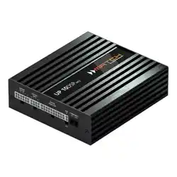
PP 86DSP
PLUG & PLAY
8-Kanal Verstärker mit integriertem 9-Kanal DSP
8-Channel Amplier with integrated 9-Channel DSP
deutsch / english

2
Sehr geehrter Kunde,
wir gratulieren Ihnen zum Kauf dieses hochwertigen
MATCH Verstärkers mit integriertem DSP.
MATCH setzt mit der PP 86DSP neue Maßstäbe im
aufstrebenden Plug & Play Markt. Dabei protieren
Sie als Kunde direkt von unserer nahezu 30 jäh-
rigen Erfahrung in der Forschung und Entwicklung
von Audiokomponenten.
Dieser Plug & Play Verstärker wurde von uns nach
neuesten technischen Erkenntnissen entwickelt
und zeichnet sich durch hervorragende Verarbei-
tung und eine überzeugende Anwendung ausge-
reifter Technologien aus.
Viel Freude an diesem Produkt wünscht Ihnen das
Team von
AUDIOTEC FISCHER
Allgemeines zum Einbau von MATCH-Kompo-
nenten
Um alle Möglichkeiten des Produktes optimal aus-
schöpfen zu können, lesen Sie bitte sorgfältig die
nachfolgenden Installationshinweise. Wir garantie-
ren, dass jedes Gerät vor Versand auf seinen ein-
wandfreien Zustand überprüft wurde.
Vor Beginn der Installation unterbrechen Sie
den Minusanschluss der Autobatterie. Wir emp-
fehlen Ihnen, die Installation von einem Einbauspe-
zialisten vornehmen zu lassen, da der Nachweis
eines fachgerechten Einbaus und Anschlusses des
Gerätes Voraussetzung für die Garantieleistungen
ist.
Installieren Sie Ihren PP 86DSP Verstärker an einer
trockenen Stelle im Auto und vergewissern Sie sich,
dass der Verstärker am Montageort genügend Küh-
lung erhält. Montieren Sie das Gerät nicht in zu klei-
ne, abgeschlossene Gehäuse ohne Luftzirkulation
oder in der Nähe von wärmeabstrahlenden Teilen
oder elektronischen Steuerungen des Fahrzeuges.
Im Sinne der Unfallsicherheit muss der Verstärker
professionell befestigt werden. Dieses geschieht
über Schrauben, die in eine Montageäche ein-
geschraubt werden, die wiederum genügend Halt
bieten muss.
Bevor Sie die Schrauben im Montagefeld befesti-
gen, vergewissern Sie sich, dass keine elektrischen
Kabel und Komponenten, hydraulische Bremslei-
tungen, der Benzintank etc. dahinter verborgen
sind. Diese könnten sonst beschädigt werden. Ach-
ten Sie bitte darauf, dass sich solche Teile auch in
der doppelten Wandverkleidung verbergen können.
Allgemeines zum Anschluss des PP 86DSP Ver-
stärkers
Der Verstärker darf nur in Kraftfahrzeuge eingebaut
werden, die den 12 V-Minuspol an Masse haben.
Bei anderen Systemen können der MATCH Verstär-
ker und die elektrische Anlage des Kfz beschädigt
werden. Die Plusleitung für die gesamte Anlage
sollte in einem Abstand von max. 30 cm von der
Batterie mit einer Hauptsicherung abgesichert wer-
den. Der Wert der Sicherung errechnet sich aus der
maximalen Stromaufnahme der Car-Hi Anlage.
Verwenden Sie zur Verbindung des MATCH
PP 86DSP Verstärkers mit dem Autoradio aus-
schließlich das beiliegende MATCH-Anschluss-
kabel! Die Verwendung eines anderen Kabels
kann zu Schäden an ihrer Anlage führen. Die
Sicherungen im Verstärker dürfen nur mit den
gleichen Werten (2 x 25 A) ersetzt werden, um
eine Beschädigung des Gerätes zu verhindern.
Höhere Werte können zu gefährlichen Folge-
schäden führen!
Die Kabelverbindungen müssen so verlegt sein,
dass keine Klemm-, Quetsch- oder Bruchgefahr be-
steht. Bei scharfen Kanten (Blechdurchführungen)
müssen alle Kabel gegen Durchscheuern gepols-
tert sein. Ferner darf das Versorgungskabel niemals
mit Zuleitungen zu Vorrichtungen des Kfz (Lüfter-
motoren, Brandkontrollmodulen, Benzinleitungen
etc.) verlegt werden.
Herzlichen Glückwunsch!
Allgemeine Hinweise
3
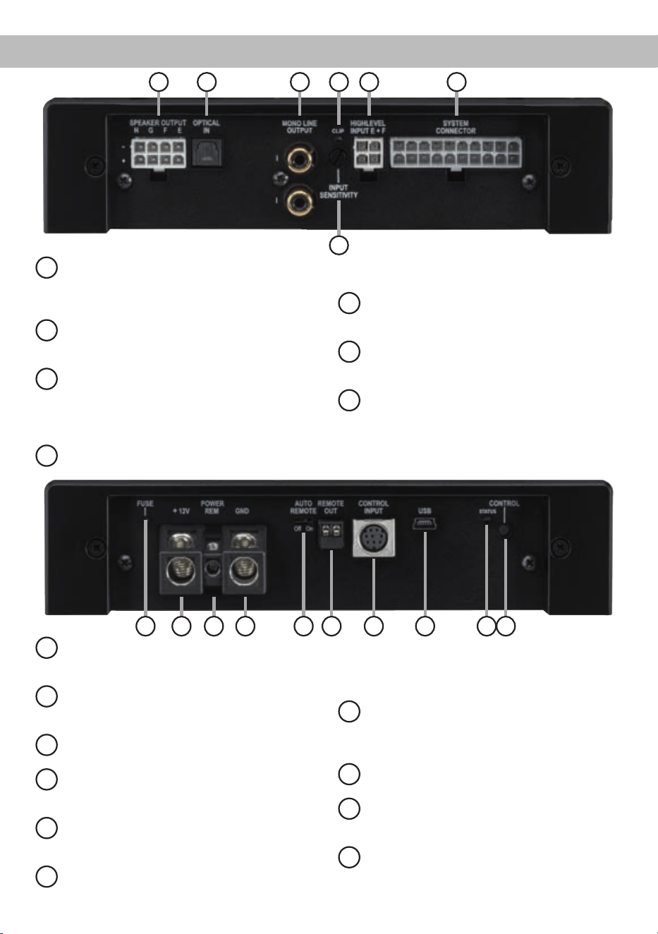
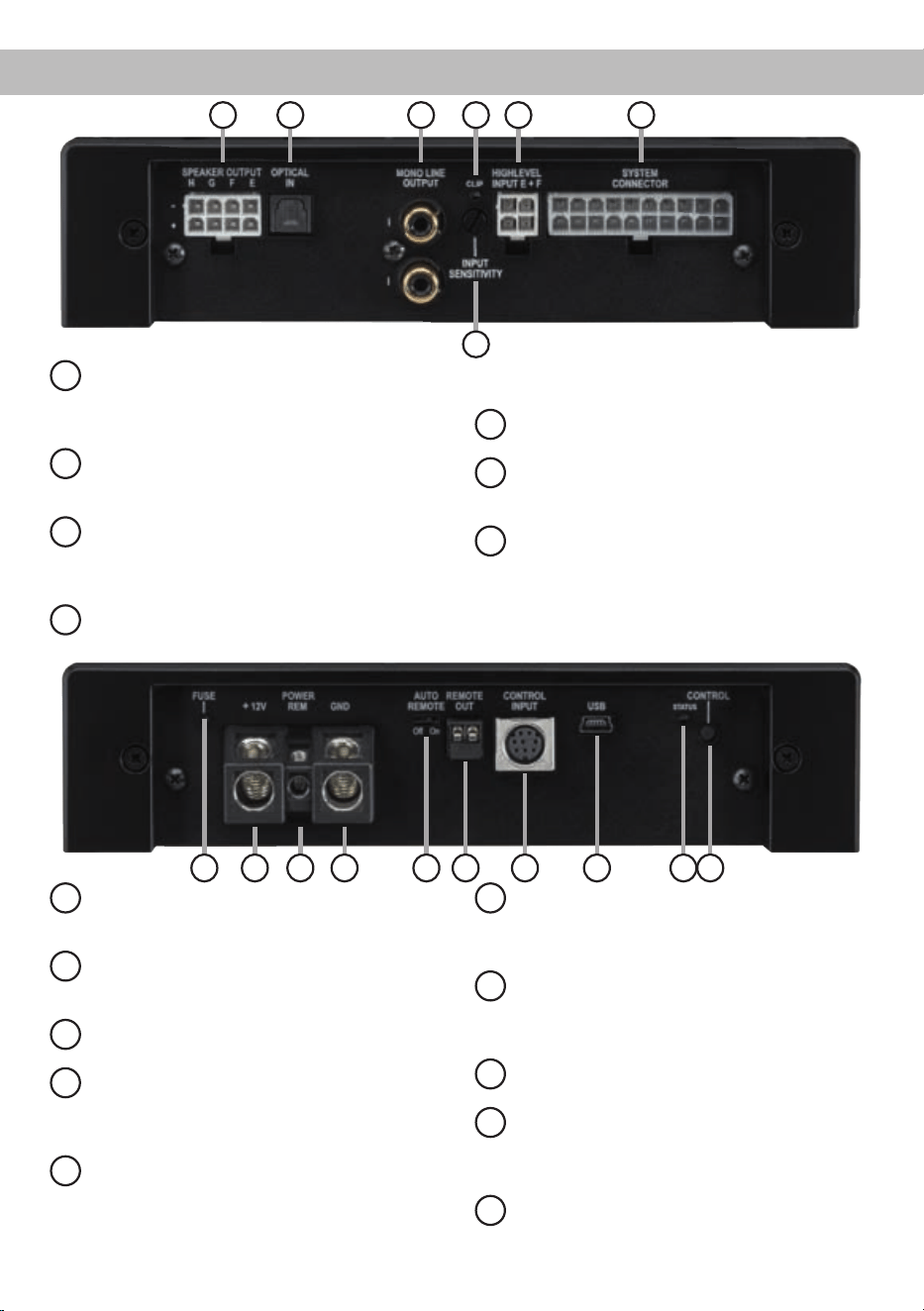
Anschluss- und Bedienelemente
1
Speaker Output E - H
Anschluss für die Lautsprecher der Kanäle
E - H oder alternativ einen passiven MATCH
PP Subwoofer.
2
Optical Input
Optischer Eingang im SPDIF-Format für digi-
tale Stereosignale.
3
Mono Line Output
Mono-Vorverstärkerausgänge zum An-
schluss weiterer Verstärker. Zum Einschalten
dieser Verstärker muss der Remote-Ausgang
verwendet werden.
4
Clipping LED
Diese LED leuchtet rot, wenn einer der
Analogeingänge übersteuert wird.
5
Input Sensitivity
Drehregler zum Anheben der Eingangsemp-
ndlichkeit.
6
Highlevel Input E + F
Hochpegel-Lautsprechereingang für die
Kanäle E und F.
7
System Connector
Anschluss für das MATCH Anschlusskabel.
Verwenden Sie ausschließlich das Original-
Anschlusskabel, um die PP 86DSP mit dem
Autoradio zu verbinden.
8
Fuse
LED zur Anzeige einer defekten Sicherung
im Gerät.
9
+12 V
Anschluss für das Versorgungsspannungs-
kabel +12 V der Batterie.
10
REM
Anschluss für die Remoteleitung.
11
GND
Anschluss des Massekabels (Minuspol der
Batterie oder Fahrzeugchassis).
12
Auto Remote
Dient zum Aktivieren bzw. Deaktivieren der
automatischen Einschaltung des Verstärkers.
13
Remote Out
Der Remote-Ausgang dient zum Einschalten
weiterer Verstärker. Dieser Ausgang muss
bei Verwendung der Mono Line Outputs ge-
nutzt werden.
14
Control Input
Multifunktionsanschluss - dient zum An-
schluss einer Fernbedienung und weiterem
MATCH PP 86DSP Zubehör.
15
USB Eingang
Dient zum Anschluss an den Computer.
16
Status LED
Die Status LED zeigt den Betriebszustand
und den ausgewählten Speicherbereich an.
17
Control Taster
Dient zum Umschalten der Sound Setups
oder zum Resetten des Gerätes.
1 2 3 4
5
6 7
9 108 16
15
14
1211 13
17

4
1
Speaker Output E - H
Diese Buchse dient entweder zum Anschluss
eines passiven Plug & Play Subwoofers, wie bei-
spielsweise dem MATCH PP 10E-D oder zum An-
schluss weiterer Lautsprecher (z.B. eines Center-
Speakers etc.). Beim Anschluss eines Plug & Play
Subwoofers werden vier der acht Verstärkerkanäle
der PP 86DSP zum Ansteuern des Subwoofers
genutzt. Dabei muss an allen vier Ausgängen ein
identisches Signal anliegen. Werden weitere Laut-
sprecher an diesen Ausgang angeschlossen, kann
jeder Verstärkerkanal einzeln mit der DSP PC-Tool
Software für den gewünschten Anwendungszweck
konguriert werden. Die Impedanz der Lautspre-
cher darf 2 Ohm nicht unterschreiten.
Achtung: Verwenden Sie zum Anschluss weiterer
Lautsprecher ausschließlich das mitgelieferte An-
schlusskabel mit dem 8-poligen Stecker und den
offenen Kabel enden.
2
Optical Input
Optischer Eingang im SPDIF-Format für den An-
schluss an Signalquellen mit digitalem Ausgang.
Die „Sampling Rate“ dieses Eingangs muss zwi-
schen 12 - 96 kHz liegen. Das Eingangssignal wird
automatisch an die interne Abtastrate angepasst.
Um diesen Eingang zu aktivieren und in der Laut-
stärke regeln zu können, wird eine optional erhält-
liche Fernbedienung empfohlen.
Hinweis:
Es können ausschließlich Stereosignale
und keine Dolby-codierten Daten verarbeitet werden!
3
Mono Line Output
Die Mono Line Outputs sind spezielle Vorverstär-
ker-Signalausgänge zum Anschluss von zusätz-
lichen Verstärkern, die durch den „Balanced Audio
Transformer“ von der Eingangsmasse getrennt
sind. Dadurch können keine Störgeräusche auf-
grund von Masseverschleifungen auftreten.
Diese Ausgänge liefern eine maximale Ausgangs-
spannung von 3 Volt RMS. Wenn Sie diese Aus-
gänge verwenden, ist es zwingend erforderlich, den
Remote-Ausgang (Remote Out) zum Einschalten
des / der angeschlossenen Verstärker/s zu verwen-
den, da ansonsten Störsignale auftreten können.
Der Remote-Ausgang schaltet sich automatisch
während des Power Save Modus sowie bei einem
Software-Update ab.
Wichtig: An beiden Cinch-Ausgängen liegt das
gleiche Audiosignal an. Dieses kann mit Hilfe der
DSP PC-Tool Software unabhängig von den ande-
ren Verstärkerkanälen konguriert werden.
4
Clipping LED
Diese LED leuchtet rot, wenn einer der sechs Hoch-
pegel-Lautsprechereingänge übersteuert wird. Die
LED hat keine Funktion bei Ansteuerung des Ver-
stärkers über den Digitaleingang (Optical Input)
oder ein MEC Modul. Sofern diese LED aueuch-
tet, muss die Eingangsempndlichkeit über den
Input Sensitivity Drehregler abgesenkt werden, bis
die LED erlischt.
5
Input Sensitivity
Mit Hilfe dieses Drehreglers kann die Eingangsemp-
ndlichkeit der Kanäle an die Ausgangsspannung
des angeschlossenen Steuergerätes angepasst
werden. Dieser Regler ist kein Lautstärkeregler,
sondern dient nur der Anpassung. Die Einstellung
dieses Reglers beeinusst nicht den optischen Ein-
gang! Der Regelbereich reicht von 11 V (Linksan-
schlag) bis 5 V (Rechtsanschlag).
Hinweis: Werkseitig ist eine Eingangsempndlich-
keit von 11 V (Linksanschlag) eingestellt.
Sofern die Lautsprecherausgänge eines üblichen
Radios verwendet werden (Highlevel), empfehlen
wir eine Einstellung von ca. 9 Volt. Dafür stellen Sie
den Drehregler vom Linksanschlag aus im Uhrzei-
gersinn etwa auf die 9 Uhr-Position ein.
6
Highlevel Input E + F
2-Kanal Hochpegel-Lautsprechereingang für die
Kanäle E und F. Mit Hilfe dieses Eingangs kann
der Verstärker direkt an die Lautsprecherausgänge
eines Werks- / Nachrüstradios oder eines Werks-
verstärkers angeschlossen werden. Die Eingangs-
empndlichkeit ist für alle Kanäle ab Werk auf
11 Volt eingestellt (Linksanschlag). Es ist jedoch
möglich, die Empndlichkeit mit dem Regler 5 (In-
put Sensitivity) zwischen 5 - 11 Volt zu variieren.
Hinweis: Diese Eingänge müssen bei Autoradios
mit 6-Kanal Highlevel-Ausgang belegt werden, da
das beiliegende MATCH-Anschlusskabel nur vier
Highlevel-Kanäle nutzt.
Achtung: Verwenden Sie zum Anschluss aus-
schließlich das mitgelieferte Anschlusskabel mit
dem 4-poligen Stecker und den offenen Kabe-
lenden.
Inbetriebnahme und Funktionen

5
7
System Connector
Diese Buchse dient zum Anschluss des mitgeliefer-
ten Kabelbaums. Verwenden Sie zur Verbindung
der MATCH PP 86DSP mit dem Originalradio aus-
schließlich den mitgelieferten Kabelbaum.
Achtung: Die Verwendung anderer oder ähnlicher
Kabelbäume kann zur Zerstörung des Verstärkers,
des Autoradios oder der angeschlossenen Laut-
sprecher führen. In jedem Fall führt dies zum Erlö-
schen der Garantie.
Wichtiger Hinweis: Über diesen Anschluss wird
die PP 86DSP nicht mit Spannung versorgt. Es ist
daher zwingend erforderlich, dafür die nachfolgend
mit (9) und (11) gekennzeichneten Klemmen zu ver-
wenden.
8
Fuse
Sollten die Sicherungen im Inneren des Gerätes
durch eine Fehlfunktion zerstört werden, wird die-
ses durch das Aueuchten der roten LED ange-
zeigt. Die Sicherungen im Verstärker dürfen nur mit
den gleichen Werten (2 x 25 A) ersetzt werden, um
eine Beschädigung des Gerätes zu verhindern. Hö-
here Werte können zu gefährlichen Folgeschäden
führen!
9
+12 V
Das +12 V Versorgungskabel ist am Pluspol der
Batterie anzuschließen. Der empfohlene Quer-
schnitt beträgt mindestens 10 mm².
10
REM
Der Remote-Eingang dient zum Einschalten der
PP 86DSP, sofern die am System Connector oder
Highlevel Input E + F angeschlossene Signalquelle
die automatische Einschaltung (Auto Remote) nicht
aktiviert oder der Verstärker bewusst nur über ein
Remote-Signal des REM ein- und ausgeschaltet
werden soll. Die Remoteleitung wird mit dem Re-
mote-Ausgang / Antennenanschluss des Steuer-
gerätes (Radio) verbunden. Dieser ist nur aktiviert,
wenn das Steuergerät eingeschaltet ist. Somit wird
der Verstärker mit dem Steuergerät ein- und ausge-
schaltet. Dieser Eingang muss nicht belegt werden,
wenn der System Connector oder Highlevel Input
E + F benutzt wird.
11
GND
Das Massekabel sollte am zentralen Massepunkt
(dieser bendet sich dort wo der Minuspol der Bat-
terie zum Metallchassis des Kfz geerdet ist) oder an
einer blanken, von Lackresten befreiten Stelle des
Kfz-Chassis angeschlossen werden. Der empfohle-
ne Querschnitt beträgt mindestens 10 mm².
12
Auto Remote
Die Einschaltung des PP 86DSP Verstärkers
erfolgt automatisch bei Ansteuerung über die
Highlevel-Eingänge des System Connectors,
den Highlevel Input E + F oder sobald ein Re-
mote-Signal am Remote-Eingang (REM) anliegt.
Mit Hilfe des Auto Remote Schalters kann die au-
tomatische Einschaltung aktiviert bzw. deaktiviert
werden. Die Deaktivierung sollte vorgenommen
werden, wenn es beispielsweise zu Störgeräuschen
beim Ein- und Ausschalten des Verstärkers kommt.
Hinweis: Wird die automatische Einschaltung des
Verstärkers deaktiviert, muss der Remote-Eingang
belegt werden. Eine automatische Einschaltung
über den Lautsprechereingang ist dann nicht mehr
möglich.
13
Remote Out
Der Remote-Ausgang dient dazu weitere Verstärker
einzuschalten. Verwenden Sie in jedem Fall diesen
Ausgang, wenn Sie weitere Verstärker an die Mono
Line Outputs der PP 86DSP anschließen, da es
ansonsten zu Störgeräuschen kommen kann. Die-
ser Ausgang aktiviert sich automatisch, sobald der
Bootvorgang des DSP abgeschlossen ist. Zudem
wird dieser Ausgang bei aktiviertem „Power Save
Mode“ und bei Betriebssoftware-Updates abge-
schaltet.
14
Control Input
Dieser Multifunktionsanschluss dient zum An-
schluss von MATCH Zubehörprodukten, wie bei-
spielsweise einer Fernbedienung mit deren Hilfe
diverse Funktionen des DSP-Verstärkers gesteuert
werden können. Die Funktionalität muss je nach
Typ der Fernbedienung zuerst im „Device Con-
guration Menu“ der DSP PC-Tool Software oder an
der Fernbedienung selbst konguriert werden.
15
USB Eingang
Mit Hilfe dieses Eingangs wird die PP 86DSP über
das beiliegende Kabel mit dem Computer verbun-
den und kann anschließend über das DSP PC-Tool

6
Inbetriebnahme und Funktionen
konguriert werden.
Hinweis: Es können keine USB Speichermedien
angeschlossen werden.
16
Status LED
Die Status LED zeigt den Betriebszustand und das
aktuell ausgewählte Setup des Verstärkers an.
Grün: Setup 1 geladen.
Orange: Setup 2 geladen.
Rot: Schutzschaltung für Unterspan-
nung aktiv.
Rot blinkend: Interner Setup-Speicher leer (Ein
neues DSP Setup muss über die
DSP PC-Tool Software einge-
spielt werden).
17
Control Taster
Mit Hilfe des Control Tasters lässt sich zwischen
den Speicherbereichen eins und zwei umschalten.
Zum manuellen Umschalten der zwei Setups muss
der Control Taster eine Sekunde lang gedrückt wer-
den. Der Umschaltvorgang wird durch einmaliges
rotes Blinken der Status LED angezeigt. Wird der
Taster länger als fünf Sekunden gedrückt, so wird
das Gerät resettet und der gesamte interne Spei-
cher gelöscht! Anschließend wird dies durch ein
rotes Dauerblinken der Status LED angezeigt.
Achtung: Nach dem Resetten des Gerätes kann
die PP 86DSP keine Audiosignale mehr wiederge-
ben, bis ein neues Sound Setup eingespielt wurde.
Spezielle Features der PP 86DSP
Class HD Technologie
In der PP 86DSP werden die Vorteile der Class H-
Technologie mit dem Prinzip eines Class D Ver-
stärkers kombiniert. Das Resultat ist ein unü-
bertroffener Wirkungsgrad, der herkömmliche
Class D-Verstärker nochmals übertrifft. Die Vorteile
spielt das Class HD-Konzept bei kleiner und mittle-
rer Aussteuerung aus, da das Netzteil die interne
Versorgungsspannung der Leistungsstufen in Ab-
hängigkeit von der Amplitude des Eingangs signals
regelt. Damit wird die mittlere, vom Verstärker er-
zeugte Verlustleistung drastisch reduziert.
Intelligenter Highlevel-Eingang
Moderne, ab Werk verbaute Autoradios werden
bezüglich der Diagnose der angeschlossenen Laut-
sprecher immer intelligenter. Wird ein Verstärker
stattdessen an das Radio angeschlossen, kommt
es meist zu Fehlermeldungen bis hin zum Wegfall
einzelner Funktionen (wie z.B. Fader).
Der neue ADEP-Schaltkreis (Advanced Diagnos-
tics Error Protection) verhindert all diese Probleme
ohne die Lautsprecherausgänge des Radios bei ho-
hen Pegeln unnötig zu belasten.
Start-Stopfähigkeit
Das Netzteil im PP 86DSP Verstärker stellt die in-
terne Spannungsversorgung auch bei kurzfristigen
Einbrüchen bis hinab zu 6 Volt sicher. Damit ist ge-
währleistet, dass der Verstärker auch beim Motor-
start voll funktionsfähig bleibt. Wenn die Bordspan-
nung für länger als 5 Sekunden unter 10,5 Volt fällt,
geht der Verstärker in den „Protect Mode“ (Status
LED leuchtet dauerhaft rot), um eine weitere Entla-
dung der Batterie zu verhindern.
Automatic Digital Signal Detection
Die Umschaltung zwischen den analogen und dem
Digitaleingang erfolgt signalgesteuert. Sobald ein
Audiosignal am Optical Input detektiert wird, schal-
tet der Verstärker auf diesen Eingang um. In der
DSP PC-Tool Software kann diese Funktion deakti-
viert oder alternativ eine manuelle Steuerung über
eine optional erhältliche Fernbedienung gewählt
werden.
Power Save Modus
Der Power Save Modus erlaubt es, die Leistungs-
aufnahme der PP 86DSP (und ggf. zusätzlich an-
geschlossener Verstärker) drastisch zu reduzieren,
wenn für länger als 60 Sek. kein Eingangssignal an-
liegt. Sobald der „Power Save Mode“ aktiv ist, wer-
den die internen Verstärkerstufen der PP 86DSP
sowie der Remote-Ausgang abgeschaltet und
damit die Stromaufnahme deutlich reduziert. Der
Verstärker geht innerhalb von 2 Sek. wieder in den
normalen Betriebszustand über, sobald ein Musik-
signal an seinem Eingang anliegt. Über die DSP
PC-Tool Software kann die Abschaltverzögerung
variiert bzw. komplett deaktiviert werden.
7
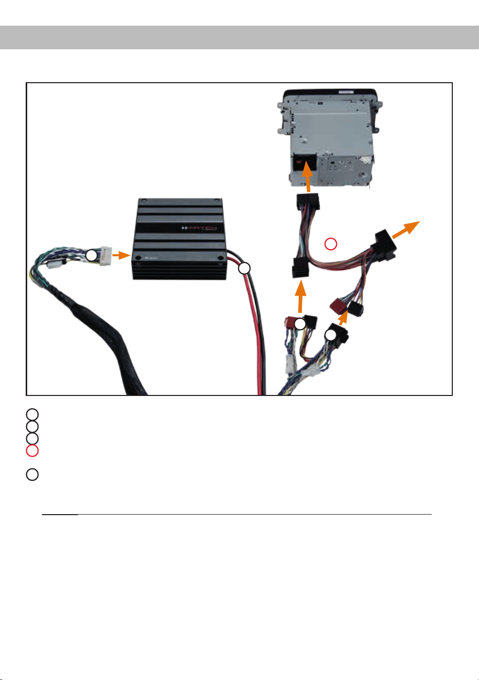
Einbau und Installation
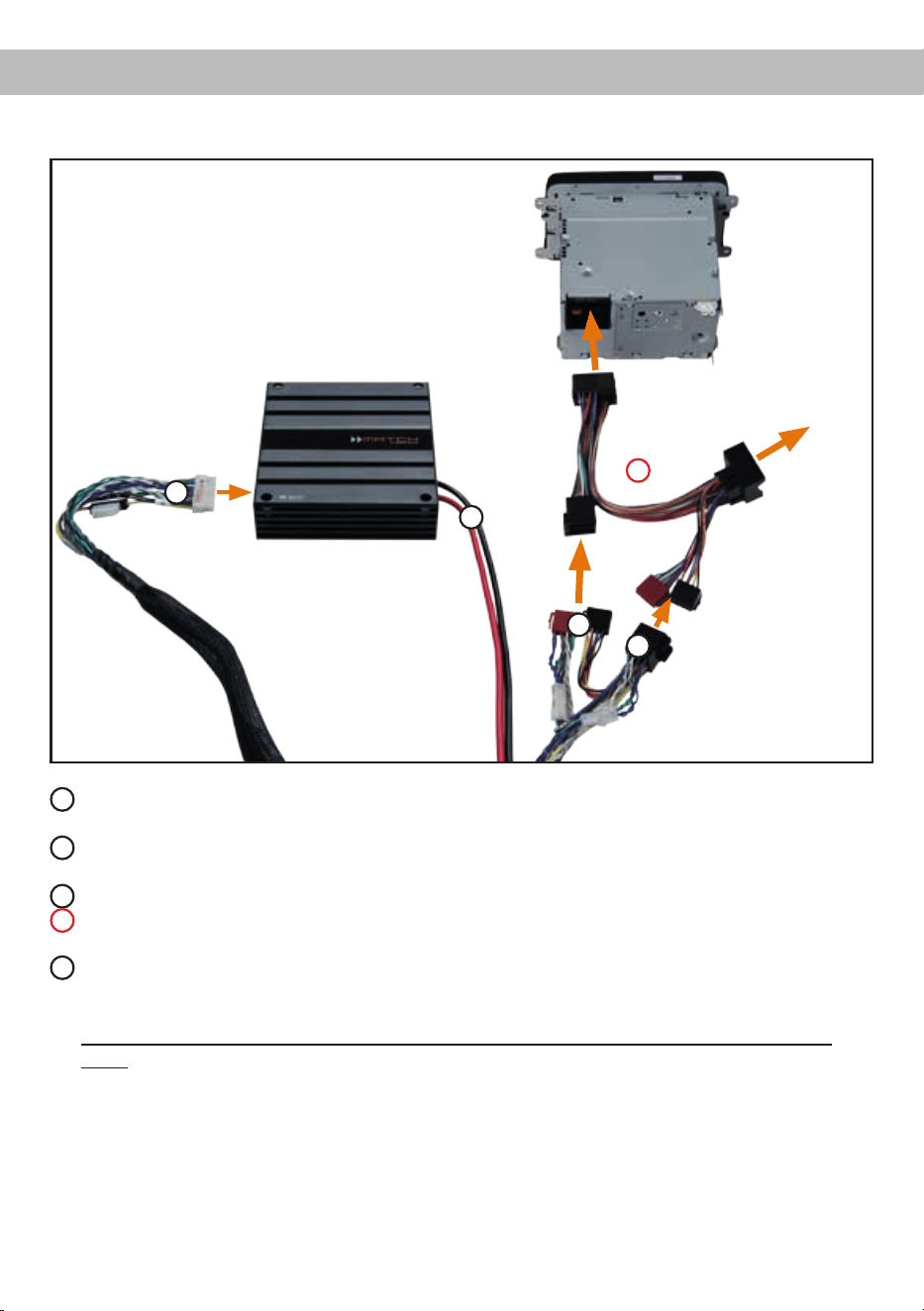
Abb. 1: Anschluss des Verstärkers an das Autoradio
1
ISO-Kupplung - hier wird der Kabelbaum des Originalradios oder ein ISO-Adapter eingesteckt.
2
ISO-Stecker - Diese werden in das Originalradio oder in den ISO-Adapter eingesteckt.
3
Dieser 20-polige Stecker wird in den MATCH PP 86DSP Verstärker eingesteckt.
4
Optional: ISO-Adapter - sollten die ISO-Stecker des mitgelieferten Kabelbaums nicht zum Originalra-
dio passen, muss ein ISO-Adapter verwendet werden.
5
Der Stromanschluss der PP 86DSP wird mit Hilfe eines geeigneten Kabels (Querschnitt min. 10 mm²)
direkt an die Batterie angeschlossen - die Plusleitung muss kurz vor der Batterie noch einmal abgesi-
chert werden.
Wichtig: Die Stromversorgung der PP 86DSP erfolgt niemals über das MATCH-Anschlusskabel!
Kupplung und Stecker
für Originalkabelbaum
oder ISO-Adapter
Kupplung für
Originalkabel-
baum
1
2
3
4
5

8
Der MATCH PP 86DSP Verstärker wird wie nach-
folgend beschrieben an das Autoradio ange-
schlossen.
Achtung: Für die Durchführung der nachfolgenden
Schritte werden Spezialwerkzeuge und Fachwis-
sen benötigt. Um Anschlussfehler und Beschädi-
gungen zu vermeiden, fragen Sie im Zweifelsfall
Ihren Fachhändler und beachten Sie zwingend die
allgemeinen Anschluss- und Einbauhinweise (siehe
Seite 2).
1. Anschluss des Plug & Play Kabelbaums
1. Nachdem das Radio mit Hilfe der entspre-
chenden Werkzeuge ausgebaut ist, trennen
Sie den Fahrzeugkabelbaum vom Autoradio.
Verbinden Sie den Fahrzeugkabelbaum an-
schließend mit der Kupplung des MATCH-
Anschlusskabels, siehe Abb. 1
1
. Je
nach Fahrzeugtyp benötigen Sie hierfür ge-
gebenenfalls einen fahrzeugspezischen
ISO-Adapter. Eine Liste aller Fahrzeuge und
der eventuell benötigten Adapter nden Sie
auf www.audiotec-scher.com.
2. Verbinden Sie die Stecker des MATCH-
Anschlusskabels mit dem Autoradio, siehe
Abb. 1
2
.
Hinweis: MOST-Bus
Bei einigen Fahrzeugen kann es notwendig
sein, die Lichtleiterverbindung aus dem Ori-
ginal-Radioanschlussstecker auszulösen
und stattdessen in den Radio-Stecker eines
ISO-Adapters einzustecken. Hierfür ist extra
eine Aussparung im ISO-Adapter vorhan-
den. Dies ist zwingend bei allen Fahrzeugen
notwendig, die einen Lichtleiteranschluss
im Originalradiokabelbaum haben.
2. Anschluss der Highlevel-Lautsprecherein-
gänge E und F (optional)
Die Hochpegel-Lautsprechereingänge E und
F können direkt mit den Lautsprecherausgän-
gen des Werks- bzw. Nachrüstradios mit Hilfe
entsprechender Kabel (Lautsprecherkabel mit
max. 1 mm² Querschnitt) verbunden werden.
Achten Sie bitte auf eine korrekte Polung!
Wenn Sie einen oder mehrere Anschlüsse ver-
polen, kann dadurch die Funktion des Verstär-
kers beeinträchtigt werden. Bei Verwendung
dieses Eingangs muss der Remote-Eingang
(REM) nicht belegt werden, da sich der Verstär-
ker automatisch einschaltet, sobald ein Laut-
sprechersignal anliegt.
Hinweis: Diese Eingänge müssen bei Autora-
dios mit 6-Kanal Highlevel-Ausgang belegt wer-
den, da das beiliegende MATCH-Anschluss-
kabel nur vier der sechs Highlevel-Kanäle
ansteuert.
3. EinstellungderEingangsempndlichkeit
Mit Hilfe des Input Sensitivity Drehreglers (Sei-
te 4, Punkt 5) kann die Eingangsempndlichkeit
an die Ausgangsspannung des angeschlos-
senen Steuergerätes angepasst werden. Die
Einstellung dieses Reglers beeinusst nicht
den optischen Eingang! Dieser Regler ist kein
Lautstärkeregler, sondern dient nur der Anpas-
sung. Die Eingangsempndlichkeit der High-
level-Eingänge der PP 86DSP ist ab Werk auf
Linksanschlag justiert.
Sofern die Lautsprecherausgänge eines üb-
lichen Radios verwendet werden (Highlevel),
empfehlen wir eine Einstellung von ca. 9 Volt.
Dafür stellen Sie den Drehregler vom Linksan-
schlag aus im Uhrzeigersinn etwa auf die
9 Uhr-Position ein.
Wichtiger Hinweis: Die Empndlichkeit darf
nur soweit erhöht werden, dass die Clipping
LED (Seite 4, Punkt 4) unter keinen Umständen
rot aueuchtet.
4. Anschluss einer digitalen Signalquelle
Sofern Sie über eine Signalquelle mit op-
tischem Digitalausgang verfügen, kann diese
an den Verstärker angeschlossen werden. Die
PP 86DSP ist werkseitig so konguriert, dass
automatisch auf den Digitaleingang umge-
schaltet wird, wenn dort ein Audiosignal anliegt.
Diese Funktion kann über die DSP PC-Tool
Software deaktiviert bzw. auf einen manuellen
Modus (in Verbindung mit einer optional erhält-
lichen Fernbedienung) geändert werden. Die
Einschaltautomatik des Verstärkers funktioniert
bei Verwendung des Digitaleingangs nicht, so
dass der Remote-Eingang (REM) zwingend be-
legt werden muss. Eine gleichzeitige Nutzung
des Digitaleingangs sowie der Hochpegel-
Signaleingänge ist möglich.
Einbau und Installation

9
Wichtig: Das digitale Audiosignal einer Quelle
ist üblicherweise nicht lautstärkegeregelt. Das
bedeutet, dass an sämtlichen Ausgängen der
PP 86DSP der volle Pegel anliegt. Dies kann im
Extremfall die angeschlossenen Lautsprecher
zerstören. Wir raten deshalb dringend dazu,
eine optionale Fernbedienung zur Einstellung
der Lautstärke der digitalen Signaleingänge zu
verwenden!
Hinweis: Die PP 86DSP kann nur unkompri-
mierte, digitale Stereo PCM-Signale mit einer
Abtastrate zwischen 12 kHz und 96 kHz verar-
beiten. Es können keine Dolby-codierten Daten
verarbeitet werden, sondern ausschließlich
Stereosignale.
5. Anschluss der Stromversorgung
Vor dem Anschluss des +12 V Versorgungs-
kabels an das Bordnetz muss die Autobatte-
rie abgeklemmt werden.
Die Stromversorgung der PP 86DSP erfolgt
niemals über das MATCH-Anschlusskabel,
sondern ausschließlich über die dafür vorhan-
denen massiven Schraubklemmen sowie ein
separates Stromversorgungskabel direkt zur
Batterie. Nutzen Sie niemals die Spannungs-
versorgung direkt vom Radio. Die PP 86DSP
hat zwar einen geringen durchschnittlichen
Strombedarf, kann aber bedingt durch die dy-
namische Netzteilregelung für Sekundenbruch-
teile sehr hohe Ströme (bis zu 50 A) ziehen.
Wichtig: Beim direkten Anschluss der
PP 86DSP an die Spannungsversorgung
des Radios riskieren Sie massive Schäden
an der Bordnetzelektrik Ihres Fahrzeuges
bis hin zu einem Kabelbrand!
Das +12 V Stromkabel ist am Pluspol der Bat-
terie anzuschließen. Die Plusleitung sollte in
einem Abstand von max. 30 cm von der Batte-
rie mit einer Hauptsicherung (50 A) abgesichert
werden. Verwenden Sie bei kurzen Leitungen
(< 1 m) einen Querschnitt von mindestens
6 mm². Bei längeren Leitungen empfehlen wir
einen Querschnitt von 10 mm² bis 16 mm².
Das Massekabel (gleicher Querschnitt wie das
+12 V Kabel) muss an einem blanken, von
Lackresten befreiten Massepunkt des Kfz-
Chassis oder direkt an dem Minuspol der Auto-
batterie angeschlossen werden.
6. Anschluss des Remote-Eingangs
Der Remote-Eingang muss mit dem Remote-
Ausgang des Radios verbunden sein, sofern
ausschließlich der Digitaleingang des Verstär-
kers als Signaleingang genutzt wird. Es wird
dringend davon abgeraten, den Remote-Ein-
gang des Verstärkers über das Zündungsplus
des Fahrzeugs zu steuern, um Störgeräusche
beim Ein- und Ausschalten zu vermeiden. Bei
Verwendung des System Connectors oder
des Highlevel Inputs E + F muss der Remote-
Eingang nicht belegt werden, sofern das ange-
schlossene Radio über BTL-Ausgangsstufen
verfügt.
7. KongurationdesRemote-Eingangs
Die Einschaltung der MATCH PP 86DSP erfolgt
automatisch bei Ansteuerung über die Hoch-
pegel-Lautsprechereingänge des System Con-
nectors, den Highlevel Input E + F oder sobald
ein Remote-Signal am Remote-Eingang (REM)
anliegt. Mit Hilfe des Auto Remote Schalters
(Seite 5, Punkt 12) kann die automatische Ein-
schaltung deaktiviert werden. Dies sollte vorge-
nommen werden, wenn es beispielsweise zu
Störgeräuschen beim Ein- und Ausschalten des
Verstärkers kommt.
Hinweis: Wird die automatische Einschaltung
des Verstärkers deaktiviert, muss der Remote-
Eingang belegt werden. Eine automatische
Einschaltung über den Hochpegel-Lautspre-
chereingang des System Connectors oder
den Highlevel Input E + F ist dann nicht mehr
möglich. Um die automatische Einschaltung
zu deaktivieren, stellen Sie den Auto Remote
Schalter auf die Schalterstellung „Off“.
8. KongurationdesinternenDSPs
Es wird dringend empfohlen vor der ersten
Inbetriebnahme die grundlegenden Einstel-
lungen im Verstärker mit Hilfe der DSP PC-
Tool Software vorzunehmen.
Eine Missachtung kann zur Zerstörung der an-
geschlossenen Lautsprecher / Verstärker füh-
ren. Speziell bei Verwendung der PP 86DSP
in vollaktiven Systemen besteht sonst Zerstö-
rungsgefahr für die Hochtöner. Informationen
zum Anschluss des Verstärkers an einen PC
nden Sie auf Seite 12.

10
9. Anschluss der Lautsprecherausgänge E - H
An die Lautsprecherausgänge können Sie
entweder einen passiven MATCH Plug & Play
Subwoofer, wie beispielsweise den MATCH
PP 10E-D oder weitere Lautsprecher (z.B. ei-
nen Center-Speaker etc.) anschließen. Zum
Anschluss eines Plug & Play Subwoofers ste-
cken Sie den 8-poligen Molex-Stecker des dem
Subwoofer beiliegenden Anschlusskabels in
den Speaker Output E - H und aktivieren diesen
anschließend im DCM Menü der DSP PC-Tool
Software.
Hinweis: Zum Ansteuern des Subwoofers wer-
den vier der acht Verstärkerkanäle genutzt.
Alternativ können die Lautsprecherausgänge
mit Hilfe des beiliegenden 8-poligen Anschluss-
kabels direkt an die Lautsprecherleitungen wei-
terer Lautsprecher verbunden werden. Verbin-
den Sie niemals die Lautsprecherleitungen mit
der Kfz-Masse (Fahrzeugkarosserie). Dieses
kann Ihren Verstärker und Ihre Lautsprecher
zerstören. Achten Sie darauf, dass alle Laut-
sprechersysteme phasenrichtig angeschlossen
sind, d.h. Plus zu Plus und Minus zu Minus.
Vertauschen von Plus und Minus hat einen To-
talverlust der Basswiedergabe zur Folge. Der
Pluspol ist bei den meisten Lautsprechern ge-
kennzeichnet.
Die Impedanz pro Kanal darf 2 Ohm nicht un-
terschreiten, da sonst die Schutzschaltung des
Verstärkers aktiviert wird.
Achtung: Verwenden Sie zum Anschluss wei-
terer Lautsprecher ausschließlich das mitgelie-
ferte Anschlusskabel mit dem 8-poligen Stecker
und den offenen Kabel enden.
10. Anschluss des Remote-Ausgangs
Dieser Ausgang (Remote Out) dient dazu, ei-
nen am Mono Line Output angeschlossenen
Zusatzverstärker mit einem Remote-Signal zu
versorgen. Bitte verwenden Sie ausschließlich
dieses Signal zur Einschaltung externer Ver-
stärker, um Ein- und Ausschaltgeräusche zu
vermeiden.
Warnhinweis:
Der PP 86DSP Verstärker hat eine höhere
Leistung als das Original-Autoradio. Die mei-
sten werkseitigen Lautsprecher können die
zusätzliche Leistung evtl. nicht dauerhaft ver-
kraften. Soweit Sie nicht die vorhandenen
Lautsprecher gegen leistungsfähigere Ausfüh-
rungen tauschen sollten, seien Sie bitte sehr
vorsichtig mit der Einstellung der Lautstärke.
Überhöhte Lautstärken, die sich durch einen
verzerrten Klang bemerkbar machen, können
die Lautsprecher beschädigen.
Wichtig: Audiotec Fischer übernimmt keinerlei
Garantie für das Zusammenspiel der PP 86DSP
in Verbindung mit werksseitig verbauten Laut-
sprechern!
Einbau und Installation
11
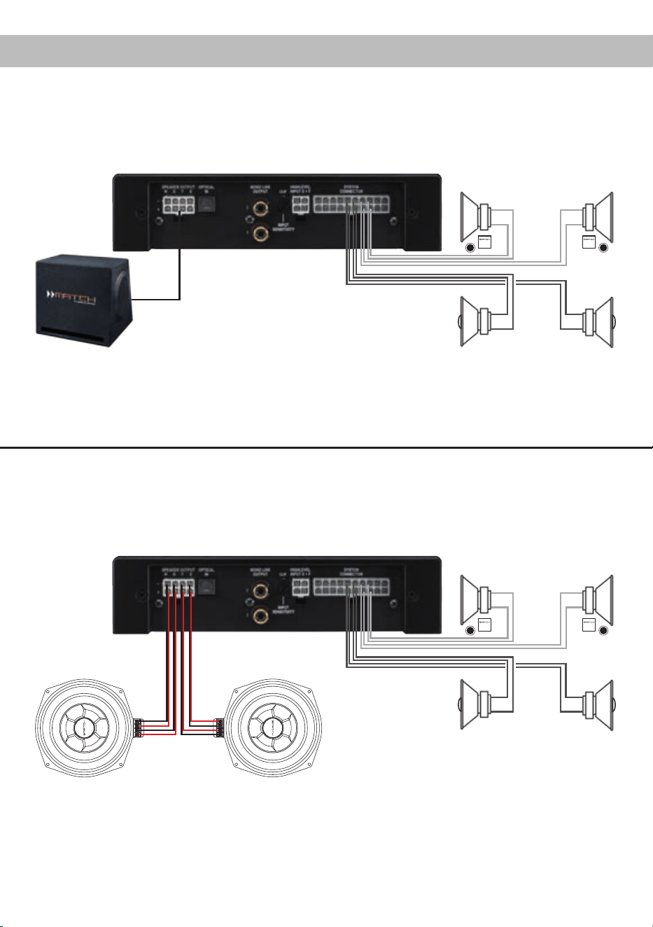
Kongurationsbeispiele
5-Kanal Anwendung
Front: 2-Wege Passivsystem
Dies ist ein klassisches 5-Kanal-Setup, bei dem vier der acht Verstärkerkanäle dazu genutzt werden,
einen MATCH-Subwoofer anzusteuern. Wir empfehlen diese Kombination nur in Verbindung mit unseren
Subwoofern PP 8E-Q oder PP10E-D.
Heck: Koaxiallautsprechersystem
2-Wege Passivsystem
+ Koaxialsystem
+ Passiver Plug & Play Subwoofer
MATCH Plug & Play
Anschlusskabel des
Subwoofers
Plug & Play Subwoofer
Bei dieser 6-Kanal-Konguration wird jedes Subwooferchassis jeweils von zwei Verstärkerkanälen der
PP 86DSP angetrieben. Dazu müssen im Audiotec Fischer DSP PC-Tool die Ausgänge des Verstärkers
als Subwooferausgänge deniert werden.
Front: 2-Wege Passivsystem
Heck: Koaxiallautsprechersystem
6-Kanal Anwendung
2-Wege Passivsystem
+ Koaxialsystem
+ Zwei Subwoofer mit Doppelschwingspule
Subwoofer MW 8BMW-D
12
Der PP 86DSP Verstärker kann mit Hilfe der DSP
PC-Tool Software frei konguriert werden. Die Soft-
ware stellt alle Funktionen übersichtlich und bedie-
nerfreundlich zur Verfügung, so dass Sie diese in-
dividuell einstellen können. Dabei können alle neun
DSP Kanäle separat eingestellt werden.
Bevor Sie den Verstärker das erste Mal an einen
Computer anschließen, gehen Sie auf unsere
Homepage und laden die aktuellste Software Ver-
sion des DSP PC-Tools herunter. Es ist ratsam re-
gelmäßig nach Updates der Software zu schauen,
damit das Gerät immer auf dem aktuellsten Stand
ist.
Die Software sowie die dazugehörige Bedienungsan-
leitung nden Sie auf www.audiotec-scher.com.
Es wird dringend empfohlen die Bedienungsanlei-
tung der Software (Sound Tuning Magazin) vor der
ersten Benutzung durchzulesen, um Komplikati-
onen und Fehler zu vermeiden.
Wichtig: Stellen Sie sicher, dass der MATCH
PP 86DSP Verstärker bei der ersten Installation der
Software noch nicht am PC angeschlossen ist. Ver-
binden Sie diesen erst, wenn die Software samt der
USB-Treiber vollständig installiert ist.
Im folgenden Abschnitt lesen Sie die wichtigsten
Schritte zum Anschluss und der ersten Inbetrieb-
nahme:
1. Laden Sie die DSP PC-Tool Software unter
www.audiotec-scher.com herunter und in-
stallieren diese auf ihrem Computer.
2. Schließen Sie danach den Verstärker mit dem
beiliegenden USB-Kabel an den Computer
an. Wenn Sie längere Distanzen zu überbrü-
cken haben, verwenden Sie bitte eine aktive
USB-Verlängerung mit integriertem Repeater
und kein passives USB-Kabel.
3. Schalten Sie erst den Verstärker ein und star-
ten Sie anschließend die Software. Sofern die
Betriebssoftware des Verstärkers nicht mehr
aktuell ist, wird diese automatisch aktualisiert.
4. Nun können Sie den MATCH PP 86DSP Ver-
stärker mithilfe der DSP PC-Tool Software
frei kongurieren. Nützliche Hinweise zur kor-
rekten Einstellung entnehmen Sie z.B. unserem
„Sound Tuning Magazin“, welches auf unserer
Website zum Download bereit steht.
Achtung: Es wird dringend empfohlen, vor der er-
sten Inbetriebnahme die Lautstärke am Radio auf
Minimum zu drehen und an den Mono Line Output
des Verstärkers noch nichts anzuschließen, bis die
grundlegenden Einstellungen im Verstärker vor-
genommen wurden. Speziell bei Verwendung der
PP 86DSP in vollaktiven Systemen besteht sonst
Zerstörungsgefahr für die Lautsprecher.
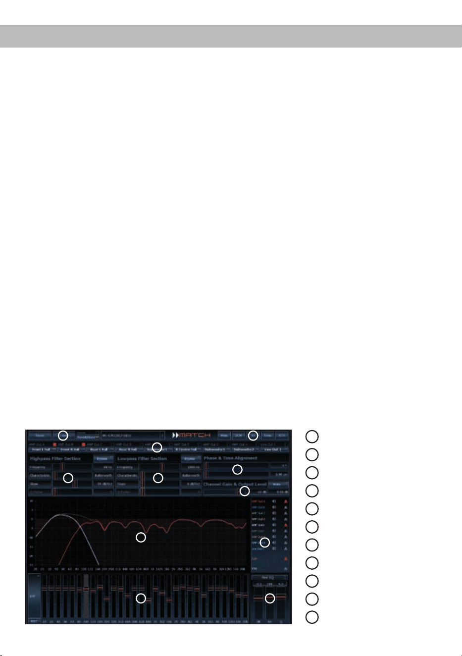
Anschluss an den Computer
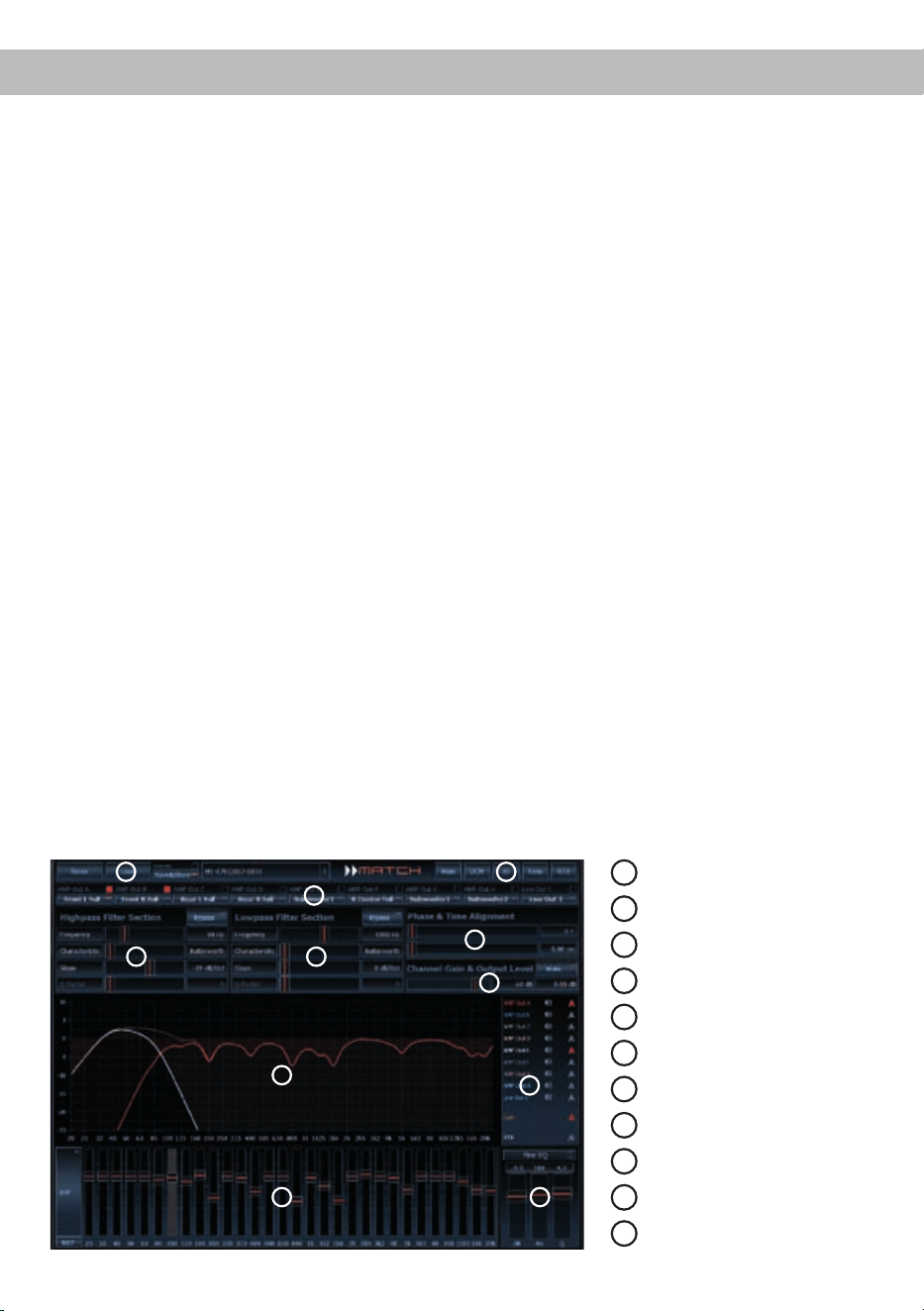
1
Laden und Speichern
2
Hauptmenü
3
Kanalkonfiguration
4
Hochpassfilter
5
Tiefpassfilter
6
Laufzeitkorrektur
7
Ausgangspegel
8
Frequenzgraph
9
Auswahl Frequenzgraphen
10
Equalizer
11
EQ Feineinstellung
8
1
6
3
4
7
5
2
9
10 11
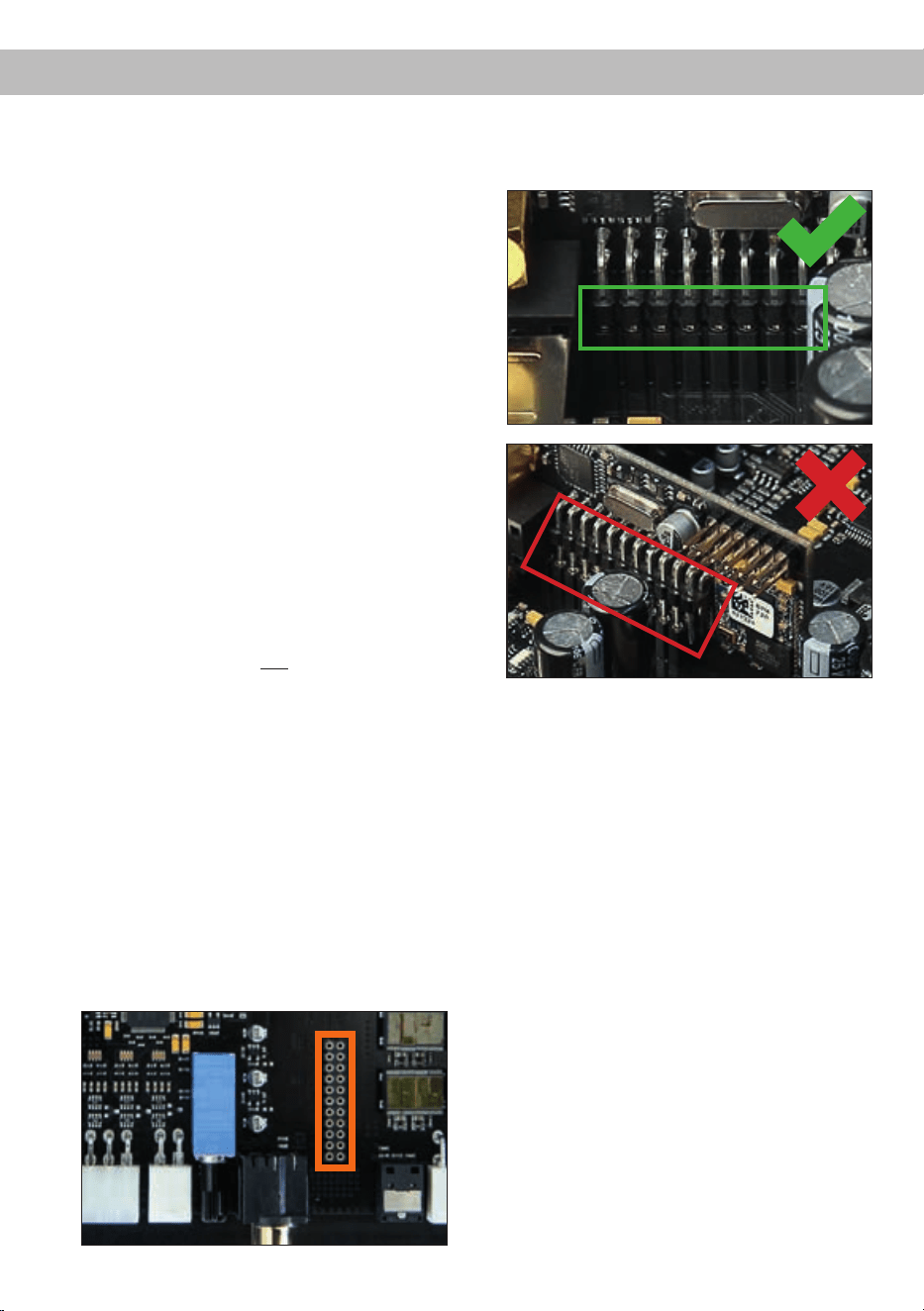
13
Einbau einer MATCH Extension Card
Der MATCH PP 86DSP Verstärker kann durch die
Montage einer MATCH Extension Card (MEC) um
weitere Funktionen erweitert werden - beispielswei-
se um eine Bluetooth
®
Audio Streaming Funktion,
einen AUX-Eingang oder einen USB Audio-Ein-
gang.
Zur Montage einer MEC muss das Seitenblech der
PP 86DSP demontiert und gegen das der MEC bei-
liegende Seitenblech ausgetauscht werden.
Achtung: Installieren Sie ausschließlich für den
PP 86DSP Verstärker vorgesehene MEC Modu-
le an der dafür vorgesehenen Position. Die Be-
nutzungeinesnichtfürdasGerätspezizierten
MEC Moduls oder eine Installation an einer nicht
dafür vorgesehenen Position im Gerät kann zu
Schäden am MEC Modul, dem Verstärker, des
Radios oder anderen angeschlossenen Geräten
führen.
Im folgenden Abschnitt nun die wichtigsten Schritte
zum Einbau und der ersten Inbetriebnahme eines
MEC Moduls:
1. Ziehen Sie zunächst alle Steckverbindungen
vom Gerät ab.
2. Lösen Sie die drei Schrauben des Seitenblechs
der Geräteseite mit dem System Connector
Eingang mit einem Kreuzschlitzschraubendre-
her und entfernen dieses.
3. Ziehen Sie nun das Bodenblech zur Seite he-
raus.
4. Bereiten Sie das Modul für den Einbau in das
Gerät vor. Informationen dazu entnehmen Sie
bitte der Bedienungsanleitung des jeweiligen
MEC Moduls.
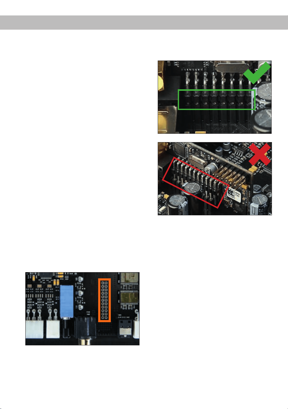
5. Stecken Sie das MEC Modul in den im Gerät
vorgesehenen Sockel (siehe Markierung im
nachfolgenden Bild).
6. Achten Sie auf den richtigen Sitz des MEC Mo-
duls und darauf, dass alle Kontaktstifte vollstän-
dig im Sockel stecken.
7. Schieben Sie das Bodenblech wieder seitlich
in das Gehäuse des Verstärkers. Anschließend
befestigen Sie das neue, dem MEC Modul
beiliegende Seitenblech mit den Kreuzschlitz-
schrauben.
8. Verschrauben Sie das MEC Modul mit dem
Seitenblech. Genaue Informationen zur Befes-
tigung entnehmen Sie bitte der Bedienungsan-
leitung des jeweiligen Moduls.
9. Schließen Sie alle Steckverbindungen wieder
an das Gerät an.
10. Schalten Sie den Verstärker ein. Das installierte
MEC Modul wird nun automatisch vom Gerät
erkannt und die Status LED des MEC Moduls
leuchtet grün.
11. Das Modul kann nun in der DSP PC-Tool Soft-
ware konguriert werden.

14
Die Garantieleistung entspricht der gesetzlichen
Regelung. Von der Garantieleistung ausgeschlos-
sen sind Defekte und Schäden, die durch Überla-
stung oder unsachgemäße Behandlung entstanden
sind. Eine Rücksendung kann nur nach vorheriger
Absprache in der Originalverpackung, einer de-
taillierten Fehlerbeschreibung und einem gültigen
Kaufbeleg erfolgen.
Technische Änderungen und Irrtümer vorbehalten!
Für Schäden am Fahrzeug oder Gerätedefekte, her-
vorgerufen durch Bedienungsfehler des Gerätes,
können wir keine Haftung übernehmen. Dieses
Produkt ist mit einer CE-Kennzeichnung versehen.
Damit ist das Gerät für den Betrieb in Fahrzeugen
innerhalb der Europäischen Union (EU) zertiziert.
Technische Daten
Garantiehinweis
Hinweis:
„Die Bluetooth
®
Wortmarke und die Logos sind eingetragene Warenzeichen der Bluetooth SIG, Inc. und jegliche Nutzung dieser Marken
durch die Audiotec Fischer GmbH geschieht unter Lizenz. Andere Handelsmarken und Handelsnamen gehören den jeweiligen Inhabern.“
Ausgangsleistung RMS / Max.
- Alle Kanäle an 4 Ohm....................................................8 x 55 / 110 Watt
- Alle Kanäle an 2 Ohm…………………………………… 8 x 70 / 140 Watt
Eingänge .........................................................................6 x Hochpegel-Lautsprechereingang
1 x Optisch SPDIF (12 - 96 kHz)
1 x Remote In
Eingangsempndlichkeit .................................................. 5 - 11 Volt
Ausgänge ........................................................................8 x Lautsprecher
2 x Cinch (mono)
2 x Remote Out
Ausgangsspannung Cinch...............................................3 Volt RMS
Frequenzbereich..............................................................20 Hz - 22.000 Hz
DSP Auösung ................................................................64 Bit
DSP Rechenleistung .......................................................295 MHz (1,2 Mrd. MAC Operationen/Sekunde)
Abtastrate ........................................................................48 kHz
Signalwandler ..................................................................A/D: BurrBrown
D/A: BurrBrown
Signal- / Rauschabstand .................................................> 103 dB (A-bewertet)
Klirrfaktor (THD) ..............................................................< 0,015 %
Dämpfungsfaktor .............................................................> 100
Eingangsimpedanz ..........................................................13 Ohm
Betriebsspannung............................................................10,5 - 16 Volt (max. 5 Sek. bis hinab zu 6 Volt)
Max. Remote-Ausgangsstrom .........................................500 mA
Abmessungen (H x B x T) ...............................................44 x 185 x 164 mm
Zusätzliche Features .......................................................Class HD-Technologie mit dynamisch geregeltem
Netzteil, Start-Stop-Fähigkeit, Control Input, USB,
MEC Slot, Auto Remote Schalter, galvanisch
getrennter Line Out

15
Dear Customer,
Congratulations on your purchase of this innovative
and high-qual ity MATCH product.
With the PP 86DSP, MATCH is setting new stan-
dards in the evolving plug & play market.
We wish you many hours of enjoyment with your
new MATCH PP 86DSP.
Yours,
AUDIOTEC FISCHER
General installation instructions for MATCH
components
To prevent damage to the unit and possible injury,
read this manual carefully and follow all installation
instructions. This product has been checked for
proper function prior to shipping and is guaranteed
against manufacturing defects.
Before starting your installation, disconnect the
battery’s negative terminal to prevent damage
totheunit,reand/orriskofinjury. For a proper
performance and to ensure full warranty coverage,
we strongly recommend to get this product installed
by an authorized MATCH dealer.
Install your PP 86DSP in a dry location with suf-
cient air circulation for proper cooling of the
equipment. The amplier should be secured to
a solid mounting surface using proper mounting
hardware. Before mounting, carefully examine the
area around and behind the proposed installa-
tion location to ensure that there are no electrical
cables or components, hydraulic brake lines or any
part of the fuel tank located behind the mounting
surface. Failure to do so may result in unpredictable
damage to these components and possible costly
repairs to the vehicle.
General instruction for connecting the
PP86DSPamplier
The PP 86DSP amplier may only be installed in
motor vehicles which have a 12 Volts negative ter-
minal connected to the chassis ground. Any other
system could cause damage to the amplier and
the electrical system of the vehicle.
The positive cable from the battery for the entire
sound system should be provided with a main fuse
at a distance of max. 30 cm from the battery. The
value of the fuse is calculated from the maximum
total current draw of the car audio system.
Use only the enclosed MATCH cable for con-
nection of the PP 86DSP. The use of other
cables can result in damage of the ampli-
er,the head unit / car radio or the connected
loudspeakers! The fuses of the amplier may
only be replaced by identically rated fuses (2 x
25A)toavoiddamageoftheamplier.
Prior to installation, plan the wire routing to avoid
any possible damage to the wire harness. All
cabling should be protected against possible
crushing or pinching hazards. Also avoid routing
cables close to potential noise sources such as
electric motors, high power accessories and other
vehicle harnesses.
Congratulations!
General instructions
16
Connectors and control units
1
Speaker Output E - H
Connector for the loudspeakers of the chan-
nels E to H. Alternatively you can directly
connect a passive MATCH PP subwoofer.
2
Optical Input
Optical input for digital stereo signals (SPDIF
format).
3
Mono Line Output
Mono line outputs for connecting external
ampliers. Make sure that the remote output
is used to turn on these devices.
4
Clipping LED
This LED lights up red if one of the analog
inputs is overdriven.
5
Input Sensitivity
Control for adjusting the input sensitivity.
6
Highlevel Input E + F
Highlevel speaker input of the channels E
and F.
7
System Connector
Connector for the MATCH cable harness.
Make sure that you only use the original ca-
ble that comes with the amplier to connect
the PP 86DSP with your car radio.
8
Fuse
This LED will light up if the fuses inside the
amplier are blown.
9
+12 V
Connector for the +12 V power cable to the
positive terminal of the battery.
10
REM
Connector for the remote cable.
11
GND
Connector for the ground cable (negative
terminal of the battery or metal body of the
vehicle).
12
Auto Remote
This switch allows to activate / deactivate
the automatic turn-on feature of the amplier.
13
Remote Out
The remote output has to be used to turn on /
off external ampliers that are connected to
the Mono Line Outputs.
14
Control Input
Multifunction interface for e.g. an optional
remote control or other MATCH PP 86DSP
accessory.
15
USB Input
Connects the PP 86DSP to your PC.
16
Status LED
This LED indicates the operating mode of the
amplier and the setup that has been cho-
sen.
17
Control pushbutton
Use this button to either switch between the
setups or initiate a reset of the device.
9 108 1615
14
1211 13
17
1 2 3 4
5
6 7

17
Initial start-up and functions
1
Speaker Output E - H
This output is used for connecting a passive
Plug & Play subwoofer like the MATCH PP 10E-D
or further loudspeakers. When connecting a
Plug & Play subwoofer, four amplier channels of
the PP 86DSP are used for driving the subwoofer.
Please make sure that in this case the output sig-
nal of all these four channels is identical. Alterna-
tively you can congure each channel individually
for other purposes via the DSP PC-Tool software
(e.g. center speaker or fully active congurations).
The impedance per channel must not be lower than
2 Ohms.
Attention: Solely use the connection cable with the
8-pole connector and ying leads which is included
in delivery!
2
Optical Input
Optical input in SPDIF format for connecting signal
sources with a digital audio output. The sampling
rate of this input must be between 12 and 96 kHz.
The input signal is automatically adapted to the in-
ternal sample rate. In order to activate and control
the volume of this input, we recommend to use an
optional remote control.
Notice: This amplier can only handle stereo input
signals and no Dolby-coded digital audio stream.
3
Mono Line Output
The Mono Line Outputs are oating-ground low-
level outputs (max. 3 Vrms) for connecting addition-
al power ampliers. A specially designed “Balanced
Audio Transformer” avoids any ground-loops that
may cause undesired alternator noise. Please
make sure that you always turn on/off external am-
pliers using the remote output (Remote Out) of the
PP 86DSP. Additionally this output will be turned off
when the “Power Save Mode” of the amplier is ac-
tive as well as during software updates.
Important: Both RCA outputs deliver the same au-
dio signal. This can be congured independently of
the other amplier channels with the DSP PC-Tool
software!
4
Clipping LED
This LED lights up red if one of the six highlevel
inputs is overdriven. The LED has no function when
an input signal is applied to the digital input (Optical
Input) or to the MEC module. If this LED lights up
reduce the input sensitivity by using the control 5
(Input Sensitivity) until the LED goes out.
5
Input Sensitivity
This control is used to adapt the input sensitivity of
the highlevel inputs to the output voltage of the con-
nected signal source. This is not a volume control,
it´s only for adjusting the ampliers gain. The con-
trol range of the highlevel input goes from 11 Volts
(max. CCW position) to 5 Volts (max. CW position).
Please note: The input sensitivity ex works is set to
11 Volts (max. CCW position). If the highlevel inputs
of the System Connector or the Highlevel Input
E + F are used in combination with a standard car
radio we recommend an input sensitivity of roughly
9 Volts. For this purpose, turn the control from max.
CCW position to 9 o’clock position.
6
Highlevel Input E + F
2-channel highlevel loudspeaker input of the chan-
nels E and F to connect the amplier directly to
loudspeaker outputs of OEM / aftermarket radios
or OEM ampliers. Input sensitivity is factory-set to
11 Volts for all channels. It is possible to vary the
sensitivity between 5 and 11 Volts with control 5 (In-
put Sensitivity).
Please note: This input has to be used for car ra-
dios with 6-channel highlevel output because the
MATCH connection cable only provides four high-
level channels.
Attention: Solely use the connection cable with the
4-pole connector and ying leads which is included
in delivery!
7
System Connector
Please use this terminal only in combination with
the cable harness that is included in the delivery of
the amplier. Never ever use any other harnesses
to connect the MATCH PP 86DSP to your head
unit / car radio.
Caution: The use of other harnesses than the one
that is supplied with the amplier may cause severe
harm to the amplier, your head unit / car radio and
your loudspeakers. In any case the warranty will be
void!
Important note: This connector does not allow
connecting the amplier to the car’s battery. It is
mandatory to use the terminals (9) and (11) which
are described in the following.

18
Initial start-up and functions
8
Fuse
If a severe malfunction inside the amplier will blow
the internal fuses the LED lights up red. The fuses
may only be replaced by identically rated fuses (2 x
25 A) to avoid damage of the amplier.
9
+12 V
Connect the +12 V power cable to the positive ter-
minal of the battery. Recommended cross section:
min. 10 mm² / AWG 8.
10
REM
The remote input has to be used to turn on/off the
PP 86DSP if the signal source which is connected
to the System Connector or Highlevel Input E + F is
not activating the “automatic turn-on” function (Auto
Remote) or if the amplier shall only be activated /
deactivated by a remote signal applied to the re-
mote input.
The remote lead should be connected to the remote
output / automatic antenna (aerial positive) output
of the head unit / car radio. This is only activated
if the head unit / car radio is switched on. Thus the
amplier is switched on and off together with the
head unit / car radio. This input needn´t to be as-
signed if the System Connector or Highlevel Input
E + F is used.
11
GND
The ground cable should be connected to a com-
mon ground reference point (this is located where
the negative terminal of the battery is grounded
to the metal body of the vehicle) or to a prepared
metal location on the vehicle chassis i.e. an area
which has been cleaned of all paint residues. Rec-
ommended cross section: min. 10 mm² / AWG 8.
12
Auto Remote
The PP 86DSP will be turned on automatically if
the highlevel inputs of the System Connector or the
Highlevel Input E + F are used or if a signal is ap-
plied to the remote input (REM) terminal.
The Auto Remote switch allows to activate / deac-
tivate the automatic turn-on feature. The feature
should be deactivated if there are e.g. disturbing
noises while switching on/off the amplier.
Note: If the automatic turn-on function is deactivat-
ed it is mandatory to use the remote input to power
up the amplier! The highlevel signal will be ignored
in this case.
13
Remote Out
We strongly recommend to use this output for turn-
ing on/off additional ampliers that are connected to
the Mono Line Outputs of the MATCH PP 86DSP.
This is essential to avoid any interfering signals.
This output is activated automatically as soon as
the booting process of the DSP is completed. Ad-
ditionally this output will be turned off during the
“Power Save Mode” or a software update process.
14
Control Input
This multi-functional connector is designed for
MATCH accessory products like a remote control
which allows to adjust several features of the am-
plier. Depending on the type of remote control, the
functionality at rst has to be dened in the “Device
Conguration Menu” of the DSP PC-Tool software
or on the remote control itself.
15
USB Input
Connect your personal computer to the PP 86DSP
using the provided USB cable. The required
PC software to congure this amplier can be
downloaded from the Audiotec Fischer website
www.audiotec-scher.com.
Please note: It is not possible to connect any USB
storage devices.
16
Status LED
The LED indicates the operating mode of the ampli-
er and which setup has been chosen.
Green: Setup 1 is loaded.
Orange: Setup 2 is loaded.
Red: Undervoltage protection circuit is
active.
Red ashing: Internal setup storage is empty (A
new setup has to be loaded via
the DSP PC-Tool software).
17
Control pushbutton
The Control pushbutton allows the user to switch
between the two setup memory positions. To switch
between the setups the button has to be pressed
and held for one second. Switching is indicated by a
single red ash of the Status LED. Pressing the but-
ton for ve seconds completely erases the internal
memory. This is indicated by a constant red ashing
of the Status LED.

19
Unique Features of the PP 86DSP
Class HD technology
The PP 86DSP combines the advantages of a
Class H technology with the principle of a class D
amplier. The result is an unsurpassed efciency
which easily outperforms any conventional Class D
amplier.
By varying the internal supply voltage depending on
the amplier’s amplitude of the input signals, idle
losses are signicantly reduced and overall efcien-
cy is close to maximum at any time.
Smart highlevel input
The latest generation of OE car radios incorpo-
rates sophisticated possibilities of diagnosing the
connected speakers. If an usual amplier will be
hooked up failure messages and loss of specic
features (e.g. fader function) are often the result -
but not with the PP 86DSP.
The new ADEP circuit (Advanced Diagnostics Error
Protection) avoids all these problems without load-
ing the speaker outputs of the OE radio during high
volumes unnecessarily.
Start-Stop capability
The switched power supply of the MATCH
PP 86DSP assures a constant internal supply volt-
age even if the battery’s voltage drops to 6 Volts
during engine crank. If the supply voltage drops be-
low 10.5 Volts for more than ve seconds the am-
plier goes to “Protect mode” (Status LED lights up
red) in order to avoid any further discharge of the
car’s battery.
Automatic Digital Signal Detection
Switching from analog input to the digital input is
done automatically as soon as a signal is detec-
ted on the Optical Input. This feature can be deac-
tivated in the DSP PC-Tool software. Alternatively
you can use an optional remote control for manual
switching between analog and digital inputs.
Power Save Mode
The Power Save Mode is incorporated in the ba-
sic setup. It allows to signicantly reduce the pow-
er consumption of the PP 86DSP and potentially
connected ampliers once there’s no input signal
present for more than 60 seconds. Please note that
in many up-to-date cars with “CAN” or any other in-
ternal bus structures it may happen that the radio
remains “invisibly” turned on for up to 45 min. even
after locking and leaving the car! Once the “Power
Save Mode“ is active the remote output and there-
fore the connected ampliers will be turned off. The
MATCH PP 86DSP will reactivate the remote output
within a second if a music signal is applied. It is pos-
sible to either modify the turn-off time of 60 sec. or
completely deactivate the “Power Save Mode” via
the DSP PC-Tool software.
Attention: After erasing the setups from memory
the MATCH PP 86DSP will not reproduce any audio
output.
20
Installation
Fig. 1 Connection of the amplier to the head unit /car radio
1
The ISO female connector will either be plugged into the vehicle harness that has been disconnected
from the car radio or a car-specic adaptor.
2
The ISO male connector will either be plugged into the head unit / car radio or into a car-specic
adaptor.
3
The 20-pole connector will be plugged into the MATCH PP 86DSP amplier.
4
Optional: car-specic adaptor – such an adaptor may be required if the ISO connectors of the
provided PP 86DSP cable harness does not t into your head unit / car radio.
5
The power supply terminal has to be connected directly to the battery - use only adequate cables
(cable cross section: min. 10 mm² / AWG 8) and the positive cable should be provided with a main
fuse at a distance of max. 30 cm from the battery.
Important: The power supply of the PP 86DSP must never be made via the MATCH connection
cable!
Male and female
connector for original
cable harness or
car-specicadaptor
Female
connector
for
original cable
harness
1
2
3
4
5
21
The MATCH PP 86DSP must be connected to the
head unit (car radio) as follows:
Caution: Carrying out the following steps will re-
quire special tools and technical knowledge. In or-
der to avoid connection mistakes and/or damage,
ask your dealer for assistance if you have any ques-
tions and follow all instructions in this manual (see
page 15).
1. Connecting the Plug & Play cable harness
1. After removing the head unit / car radio
from the dash using appropriate tools,
disconnect the vehicle harness from the
car radio. Next, connect the vehicle har-
ness to the female connector of the
MATCH cable harness, see g.1
1
.
Depending on your car an additional car-spe-
cic adaptor may be required. A list of all cars
and the respective adaptors can be found on
www.audiotec-scher.com.
2. Connect the male connector of the MATCH
cable harness or the car-specic adaptor to
the head unit / car radio, seeg.1
2
.
Note - Cars equipped with MOST bus:
In cars equipped with MOST bus structure
it is mandatory to unplug the ber-optic
cable from the original car radio connector
and insert it into the car radio connector
of the MATCH cable harness which has a
dedicated recess for this.
2. Connecting the highlevel speaker inputs E
and F (optionally)
The highlevel loudspeaker inputs E and F can
be connected directly to the loudspeaker out-
puts of an OEM or aftermarket radio using
appropriate cables (loudspeaker cables with
1 mm² / AWG 18 max.).
Make sure that the polarity is correct. If one or
more connections have reversed polarity it may
affect the performance of the amplier. If this
input is used the remote input (REM) does not
need to be connected as the amplier will au-
tomatically turn on once a loudspeaker signal
is received.
Please note: This input has to be used for car
radios with 6-channel highlevel output because
the MATCH connection cable only provides four
highlevel channels.
3. Adjustmentoftheinputsensitivity
The Input Sensitivity control (page 17, item 5) is
used to adapt the input sensitivity to the output
voltage of the connected head unit / car radio.
Adjustments with this control do not affect the
optical input! This control is no volume control
and is only for adapting the input sensitivity. The
ex works setting of the highlevel input sensitivi-
ty of the PP 86DSP is the maximum coun ter-
clockwise position.
If the highlevel inputs of the System Connector
or the Highlevel Input E + F are used in combi-
nation with a standard car radio we recommend
an input sensitivity of roughly 9 Volts. For this
purpose turn the control from max. CCW posi-
tion to 9 o’clock position.
Important note: Please make sure that you
choose an appropriate sensitivity setting that
the Clipping LED (page 17, item 4) never lights
up.
4. Connecting a digital signal source
If you have a signal source with an optical digital
output you can connect it to the amplier using
the appropriate input. In standard conguration
the MATCH PP 86DSP automatically activates
the used digital input if a digital audio signal is
detected. This function can be deactivated via
the DSP PC-Tool software. Alternatively you
can manually activate the digital input if you are
using the optional remote control.
The automatic turn-on circuit does not work
when the digital input is used. Therefore it is
mandatory to connect the remote input (REM).
Please note that it is possible to connect a
source to the digital input and the highlevel in-
puts at the same time.
Important: The signal of a digital audio source
normally does not contain any information about
the volume level. Keep in mind that this will
lead to full level on the outputs of the MATCH
PP 86DSP. This may cause severe damage to
your speakers. We strongly recommend to use
an optional remote control for adjusting the vol-
ume level of the digital signal input!
Information: The PP 86DSP can only handle
uncompressed digital stereo signals in PCM

22
Installation
format with a sample rate between 12 kHz and
96 kHz and no Dolby-coded signals.
5. Connection to power supply
Make sure to disconnect the battery before
installing the MATCH PP 86DSP!
The power supply of the PP 86DSP never ever
occurs via the MATCH cable harness. Always
directly connect the massive screw terminals of
this amplier to your car’s battery! Never use
the power leads of the car radio itself! Though
the PP 86DSP only has a limited average pow-
er consumption, it may draw very high currents
(up to 50 A) for the fraction of a second due to
its dynamically controlled internal power supply.
Important: You may risk a severe damage of
yourheadunit/carradioandotherelectron-
ic components inside your vehicle or even a
cablereifyouusethecarradioharnessfor
the power supply of the PP 86DSP!
Connect the +12 V power cable to the positive
terminal of the battery. The positive wire from
the battery to the amplier power terminals
needs to have an inline fuse (50 A) at a distance
of less than 12 inches (30 cm) from the battery.
If your power wires are short (less than 1 m /
40”) then a wire gauge of 6 mm² / AWG 10 will
be sufcient. In all other cases we strongly rec-
ommend gauges of 10 - 16 mm² / AWG 8 – 6!
The ground cable (same gauge as the +12 V
wire) should be connected to a common ground
reference point (this is located where the neg-
ative terminal of the battery is grounded to the
metal body of the vehicle) or to a prepared met-
al location on the vehicle chassis, i.e. an area
which has been cleaned of all paint residues.
6. Connecting the remote input
The remote input has to be connected to the ra-
dio remote output if the ampliers Optical Input
is solely used as signal input. We do not recom-
mend controlling the remote input via the igni-
tion switch to avoid pop noise during turn on/off.
If the highlevel inputs of the System Connector
or the Highlevel Input E + F are used this input
does not need to be connected as long as the
car radio has BTL output stages.
7. Congurationoftheremoteinput
The PP 86DSP will be turned on automatically
if the highlevel inputs of the System Connector
or the Highlevel Input E + F are used or if a sig-
nal is applied to the remote input terminal. The
Auto Remote switch (page 18, item 12) allows
to deactivate the automatic turn-on feature. The
feature should be deactivated if there are e.g.
noises while switching on/off the amplier.
Note: If the automatic turn-on function is deac-
tivated it is mandatory to use the remote input
terminal to power up the amplier! The highlevel
signal of the System Connector and High-
level Input E + F will be ignored in this case.
To deactivate the automatic turn-on feature you
have to change the position of the Auto Remote
switch to “Off”.
8. CongurationoftheinternalDSP
The general amplier settings should be
conducted with the DSP PC-Tool software
beforeusingtheamplierforthersttime.
Ignoring this advice may result in damaging the
connected speakers / ampliers. Especially if
the PP 86DSP will be used to drive fully active
speaker systems, a wrong setup can destroy
your tweeters right away.
Information about connecting the PP 86DSP to
a computer can be found on page 25.
9. Connecting the loudspeaker outputs E - H
The loudspeaker outputs allow to connect a
passive Plug & Play subwoofer like the MATCH
PP 10E-D or further loudspeakers (e.g. cen-
ter speaker etc.). For the connection of a
Plug & Play subwoofer you have to connect the
8-pole Molex connector of the connection ca-
ble which is delivered with the subwoofer to the
Speaker Output E - H.
Afterwards the appropriate subwoofer has to be
activated in the DCM menu of the DSP PC-Tool
software.
Note: The PP 86DSP uses four amplier chan-
nels for driving the subwoofer.
Alternatively the loudspeaker outputs can be
connected directly to the wires of further loud-
speakers by using the 8-pole connection cable
which is included in delivery. Never connect
any of the loudspeaker cables with the chassis

23
ground as this will damage your amplier and
your speakers. Ensure that the loudspeakers
are correctly connected (in phase), i.e. plus to
plus and minus to minus. Exchanging plus and
minus causes a total loss of bass reproduction.
The plus pole is indicated on most speakers.
The impedance of the speakers must not be
lower than 2 Ohms, otherwise the amplier pro-
tection will be activated.
Attention: Solely use the connection cable with
the 8-pole connector and ying leads which is
included in delivery for connecting further loud-
speakers!
10. Connecting the remote output
This output (Remote Out) is used to supply
remote signals to additional amplier/s that
are connected to the Mono Line Output of the
PP 86DSP. Always use this remote output sig-
nal to turn on the ampliers in order to avoid on/
off switching noises.
Caution:
ThePP86DSPamplierhasahigherpowerout-
putthantheheadunit/carradioitself.Mostof
the OE speakers in the car will not be able to
handle this extra power permanently. As long
as you do not replace the original speakers by
loudspeakers with higher power handling be
very careful when you crank up the volume. If
you hear strong distortion, please reduce the
volume to an appropriate level in order to avoid
damaging your speakers.
Note: Audiotec Fischer is not responsible for
any damages to OE speakers that are used in
combination with the PP 86DSP!

24
Congurationexamples
5-channel application
Front: 2-way passive system
This is a classical 5-channel setup where four of the eight amplier channels are used to drive a MATCH
subwoofer. We strongly recommend to use this conguration only in combination with our subs PP 10E-D
or PP 8E-Q.
Rear: Coaxial system
2-way passive system
+ Coaxial system
+ Passive Plug & Play subwoofer
MATCH Plug & Play
subwoofer connection
cable
Plug & Play subwoofer
In this 6-channel conguration each subwoofer chassis will be driven with two channels of the PP 86DSP.
For this conguration it is necessary to dene the outputs of the PP 86DSP with the Audiotec Fischer
DSP PC-Tool software as subwoofer outputs.
Front: 2-way passive system
Rear: Coaxial system
6-channel application
2-way passive system
+ Coaxial system
+ Two subwoofers with dual voice coil
Subwoofer MW 8BMW-D
25
It is possible to freely congure the MATCH
PP 86DSP with our DSP PC-Tool software.
The user interface is designed for easy handling of
all functions and allows an individual adjustment of
each of the nine DSP channels. Prior to connect-
ing the amplier to your PC visit our website and
download the latest version of the DSP PC-Tool
software.
Check from time to time for software updates. You
will nd the software and the respective user manu-
al on www.audiotec-scher.com.
We strongly recommend to carefully read the user
manual (Sound Tuning Magazine) before using the
software for the rst time in order to avoid any com-
plications and failures.
Important: Make sure that the amplier is not con-
nected to your computer before the software and
USB driver are installed!
In the following the most important steps how to
connect and the rst start-up are described:
1. Download the latest version of the
DSP PC-Tool software (available on our web-
site www.audiotec-scher.com) and install it
on your computer.
2. Connect the amplier to your computer using
the USB cable that is included in delivery. If you
have to bridge longer distances please use an
active USB extension cable with integrated re-
peater and no passive extension.
3. Turn on the amplier and start the software after
the Status LED lights up green. The operating
software will be updated automatically to the
latest version if it is not up-to-date.
4. Now you are able to congure your MATCH
PP 86DSP with our intuitive DSP PC-Tool
software. Nevertheless, interesting and useful
hints can be found e.g. in our “Sound Tuning
Magazine”, which can be downloaded for free
from our website.
Caution: We highly recommend to set the volume
of your head unit / car radio to minimum position
during rst start-up. Additionally no devices should
be connected to the Mono Line Output until gener-
al settings in the DSP PC-Tool software have been
made. Especially if the PP 86DSP will be used in
fully active applications, a wrong setup can destroy
your speakers right away.
Connection to a PC
1
Load and save
2
Main menu
3
Channel configuration
4
Highpass filter
5
Lowpass filter
6
Time alignment
7
Output level
8
Frequency graph
9
Range of frequency graphs
10
Equalizer
11
EQ fine adjustment
8
1
6
3
4
7
5
2
9
10 11
26
Installation of a MATCH Extension Card
It is possible to extend the functionality of the
MATCH PP 86DSP amplier by inserting an option-
al MATCH Extension Card (MEC) - for example a
Bluetooth
®
Audio Streaming module, an AUX input
or an USB audio input.
To install a MATCH Extension Card it is necessary
to remove the side panel of the PP 86DSP and re-
place it by the new side panel that comes with the
MEC module.
Attention: Install the MEC module only in the
designated device and its specic slot. Using
the MEC module in other devices or slots can
result in damage of the MEC module, the ampli-
er,theheadunit/carradioorotherconnected
devices!
Read in the following the steps how to install a MEC
module:
1. First disconnect all cables from the device.
2. Dismantle the side panel where the System
Connector input is located by removing the Phil-
lips screws.
3. Pull out the bottom plate.
4. Prepare the module for installing it into the de-
vice. Any further mounting information will be
found in the instruction manual of the respective
MEC module.
5. Insert the MEC module into the specic slot of
the device which is marked in the following pic-
ture.
6. Make sure that the MEC module is installed
properly and all pins are fully inserted into the
socket.
7. Reinsert the bottom plate and x the new side
panel which is delivered with the MEC module
with the Phillips screws.
8. Bolt the MEC module to the side panel. Pre-
cise mounting information will be found in
the instruction manual of the respective MEC
module.
9. Reconnect all cables to the device.
10. Turn on the amplier. The MEC module is auto-
matically detected by the device and the Status
LED of the MEC module lights up green.
11. Now you are able to congure the MEC module
in the DSP PC-Tool software.

27
The limited warranty comply with legal regulations.
Failures or damages caused by overload or im-
proper use are not covered by the warranty. Please
return the defective product only with a valid proof
of purchase and a detailed malfunction description.
Technical specications are subject to change!
Errors are reserved! For damages on the vehicle
and the device, caused by handling errors of the
device, we can’t assume liability. These devices are
certied for the use in vehicles within the European
Community (EC).
Technical Data
Warranty Disclaimer
Note:
“The Bluetooth
®
word mark and logos are registered trademarks owned by Bluetooth SIG, Inc. and any use of such marks by
Audiotec Fischer GmbH is under license. Other trademarks and trade names are those of their respective owners.”
Output power RMS / max.
- All channels @ 4 Ohms ................................................. 8 x 55 / 110 Watts
- All channels @ 2 Ohms ................................................. 8 x 70 / 140 Watts
Inputs ............................................................................... 6 x Highlevel speaker input
1 x Optical SPDIF (12 - 96 kHz)
1 x Remote In
Input sensitivity ................................................................5 - 11 Volts
Outputs ............................................................................8 x Speaker
2 x RCA / Cinch (mono)
2 x Remote Out
Output voltage RCA / Cinch.............................................3 Volts RMS
Frequency response ........................................................ 20 Hz - 22,000 Hz
DSP resolution .................................................................64 Bit
DSP power ......................................................................295 MHz (1.2 billion MAC operations/second)
Sampling rate ..................................................................48 kHz
Signal converters ............................................................. A/D: BurrBrown
D/A: BurrBrown
Signal-to-noise ratio.........................................................> 103 dB (A-weighted)
Distortion (THD) ...............................................................< 0.015 %
Damping factor ................................................................> 100
Input impedance ..............................................................13 Ohms
Operating voltage ............................................................10.5 -16 Volts (max. 5 sec. down to 6 Volts)
Max. remote output current .............................................500 mA
Dimensions (H x W x D) ..................................................44 x 185 x 164 mm / 1.73 x 7.28 x 6.46”
Additional features ........................................................... Class HD technology with dynamically controlled
power supply, Start-Stop capability, Control Input,
USB, MEC slot, Auto Remote switch, galvanically
isolated Line Out

Audiotec Fischer GmbH
Hünegräben 26 · 57392 Schmallenberg · Germany
Tel.: +49 2972 9788 0 · Fax: +49 2972 9788 88
E-mail: match@audiotec-scher.com · Internet: www.audiotec-scher.com