MILWAUKEE ELECTRIC TOOL CORPORATION
13135 W. Lisbon Road, Brookfi eld, WI 53005
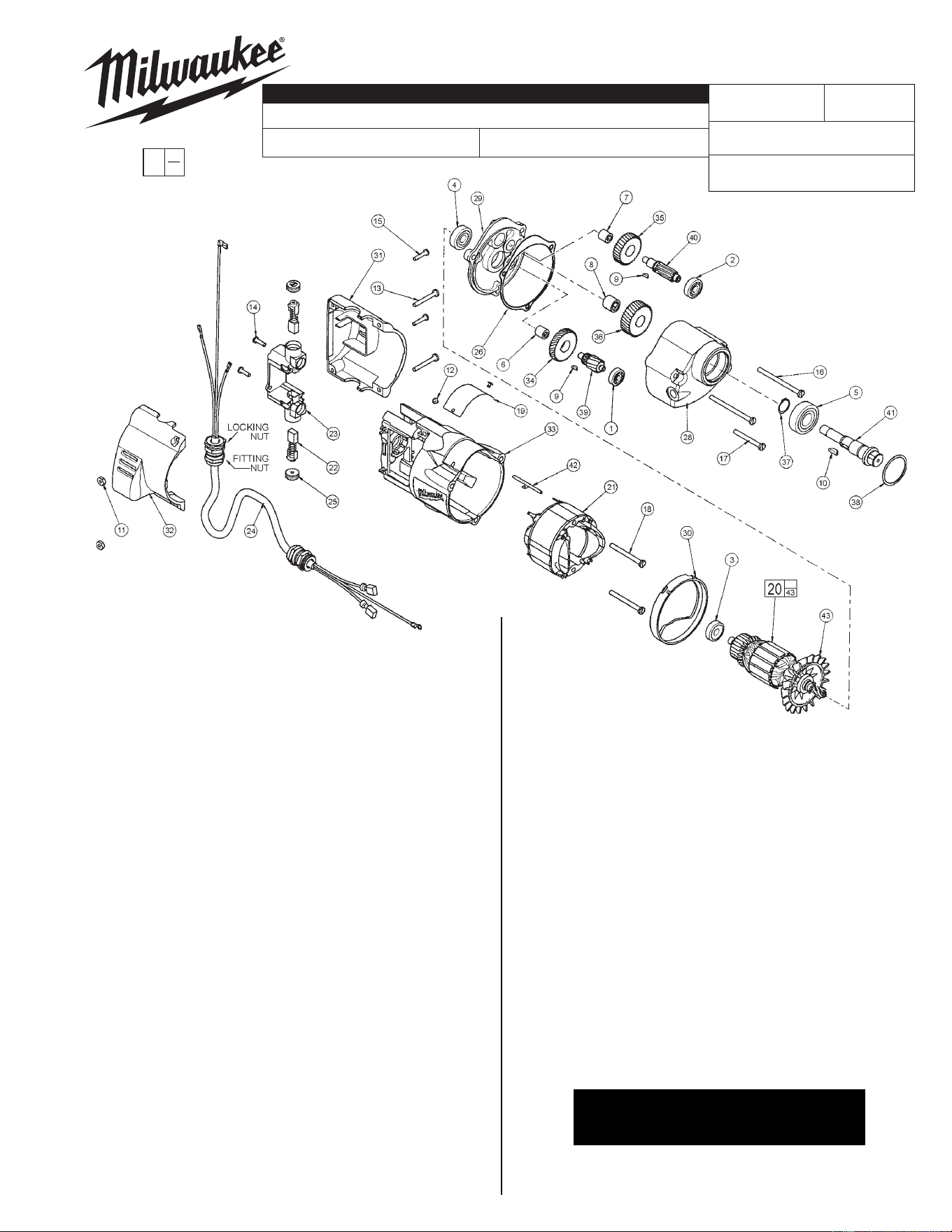
Drwg. 8
FIG. PART NO. DESCRIPTION OF PART QTY.
1 02-04-0640 Ball Bearing (1)
2 02-04-0820 Ball Bearing (1)
3 02-04-0845 Ball Bearing (1)
4 02-04-0911 Ball Bearing (1)
5 02-04-1536 Ball Bearing (1)
6 02-50-1640 Needle Bearing (1)
7 02-50-1645 Needle Bearing (1)
8 02-50-2440 Needle Bearing (1)
9 06-42-0800 Woodruff Key (2)
10 06-42-2000 Woodruff Key (1)
11 06-55-0835 Hex Nut (2)
12 06-72-1710 Nameplate Rivet (2)
13 06-82-2390 8-32 x 1-1/4" Pan Hd. Slotted T-20 (2)
14 06-82-7240 6-19 x .50 Pan Hd. Slotted Plastite T-15 (2)
15 06-82-9207 6-19 x .708 Pan Hd. PT Screw T-10 (2)
16 06-82-7375 8-16 x 2.50 Pan Hd. Slotted Plastite T-20 (2)
17 06-82-7382 8-16 x 1.625 Pan Hd. Slotted Plastite T-20 (1)
18 06-82-7410 8-16 x 1.875 Pan Hd. Slotted Plastite T-20 (2)
19 12-99-7595 Service Nameplate (1)
20 16-30-1480 Armature (1)
21 18-31-0500 Field (1)
22 22-18-1010 Carbon Brush Assembly (2)
23 22-22-1385 Brush Holder Assembly (1)
24 22-64-3290 Motor Cord Assembly (1)
25 23-44-0125 Brush Holder Cap (2)
26 43-44-1075 Gasket (1)
28 28-14-1922 Gearcase (1)
29 28-28-0611 Diaphragm (1)
30 31-05-0055 Baffl e (1)
31 31-15-2060 Motor Cover-Left Half (1)
32 31-15-2061 Motor Cover-Right Half (1)
33 31-50-0020 Motor Housing (1)
34 32-40-1251 Intermediate Gear (1)
35 32-75-2051 2nd Intermediate Gear (1)
36 32-75-2651 Spindle Gear (1)
37 34-60-1200 External Retaining Ring (1)
38 34-80-2500 Retaining Ring (1)
39 36-66-2811 Intermediate Pinion (1)
58-01-1840
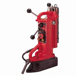
4270-20
54-46-0400
373A
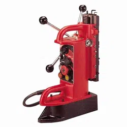
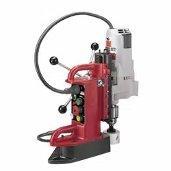
MAG STAND ASSEMBLY
REVISED BULLETIN
DATE
SERVICE PARTS LIST
BULLETIN NO.
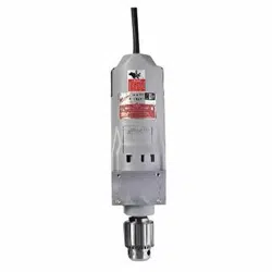
DRILL MOTOR WIRING INSTRUCTION
CATALOG NO.
SPECIFY CATALOG NO. AND SERIAL NO. WHEN ORDERING PARTS
STARTING
SERIAL NUMBER
Aug. 2011
EXAMPLE:
Component Parts (Small #) Are Included
When Ordering The Assembly (Large #).
0
00
FIG. PART NO. DESCRIPTION OF PART QTY.
40 36-66-3980 2nd Intermediate Pinion (1)
41 38-50-5485 Spindle (1)
42 44-60-0530 Grounding Pin (1)
43 22-84-0531 Fan (1)
23-94-6120 Leadwire Assembly (Not Shown) (1)
23-94-6370 Leadwire Assembly (Not Shown) (1)
FIG. NOTES:
3 Ball bearing seal to face towards the commutator.
3,4,20 Press ball bearings to armature shaft shoulder.
6,7,29 Press needle bearings to .105 ± .005 above machined
face of diaphragm.
24,31,32 Using a 20mm crows foot wrench, apply 120 in/lbs of
torque to fi tting nut and 55 in/lbs of torque to locking nut
when assembling the motor cord assembly to the
motor covers.
FIG. LUBRICATION:
1,28 Apply 3.75 oz. type "Y" grease, No. 49-08-5270 near
ball bearing #1 in gearcase.
MAG STAND WIRING INSTRUCTION
54-30-0450
SEE BULLETIN NO. 54-30-0450 FOR
OPERATIONAL CHECK LIST AND
WIRING INSTRUCTIONS FOR MAG STANDS
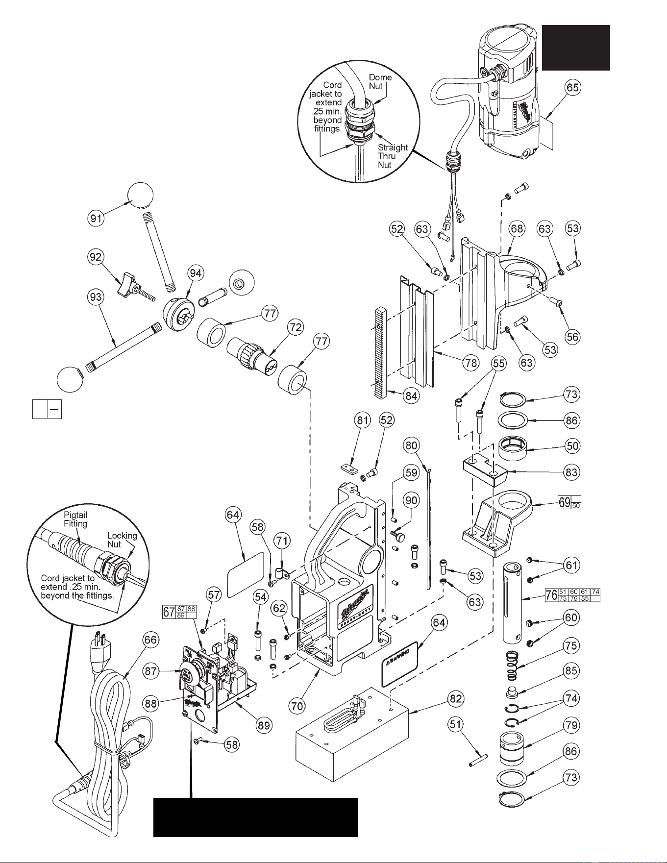
Using a 7/8" crows foot wrench, apply
45 in/lbs of torque to the pigtail fi tting and
35 in/lbs of torque to the locking nut
when assembling the power cord (66)
to the control panel (67).
Using a 20mm crows foot wrench,
apply 55 in/lbs of torque to the
straight thru fi tting and 120 in/lbs
of torque to the dome nut
when assembling the
motor cord to the stand.
Apply Loctite
222MS to
Set Screws (59).
SEE BULLETIN NO. 54-30-0450 FOR
OPERATIONAL CHECK LIST AND
WIRING INSTRUCTIONS FOR MAG STANDS
EXAMPLE:
Component Parts (Small #)
Are Included When Ordering
The Assembly (Large #).
0
00
SEE PAGE 1
TO SERVICE
DRILL MOTOR
ASSEMBLY
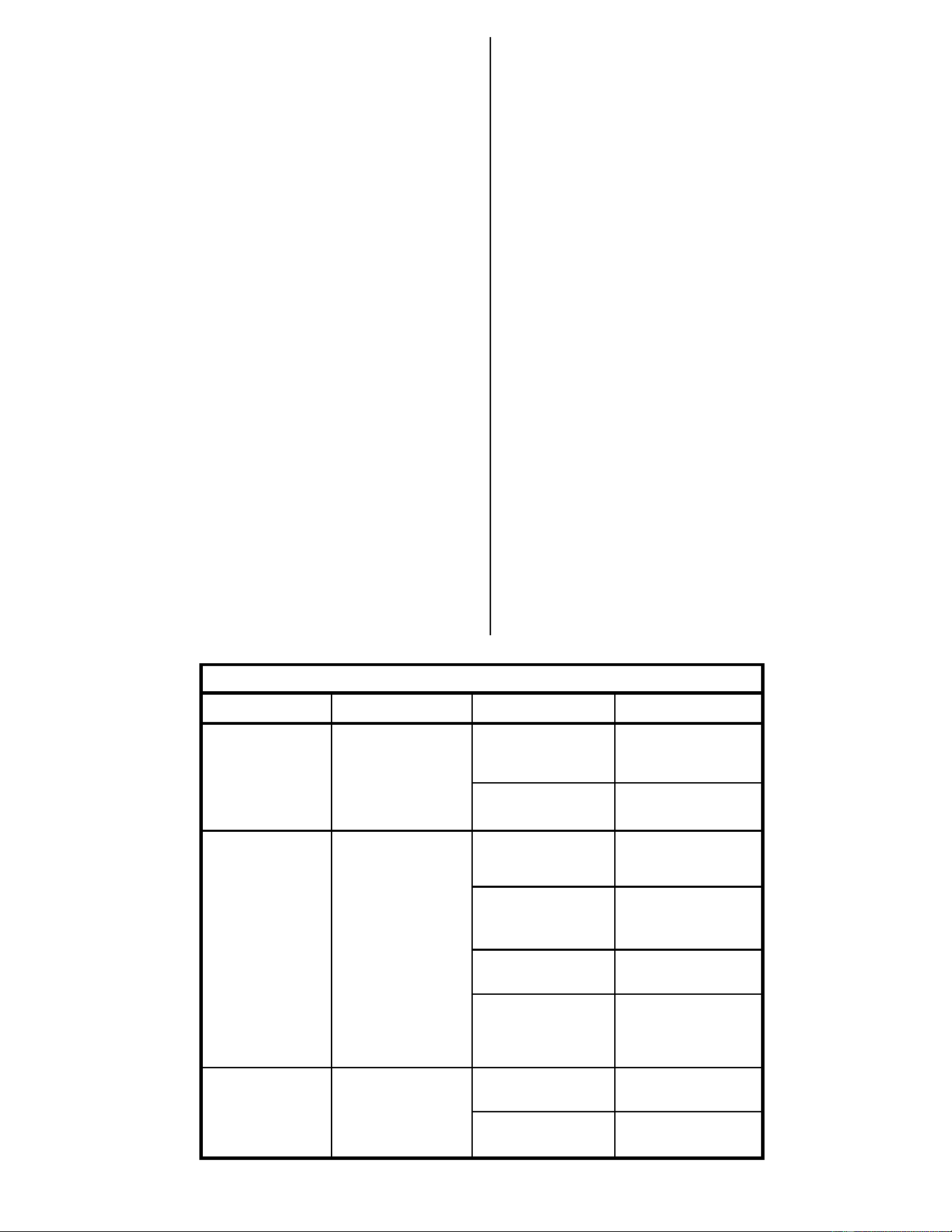
FIG. PART NO. DESCRIPTION OF PART QTY.
50 --------------- Needle Bearing (1)
51 --------------- Roll Pin (1)
52 06-75-2900 1/4 x 3/8" Socket Head Screw (2)
53 06-75-3005 1/4 x 5/8" Socket Head Screw (5)
54 06-75-3100 1/4-20 x 1.00" Socket Head Screw (2)
55 06-75-5865 1/4-20 x 1.25" Socket Head Sems Screw (2)
56 06-81-4770 1/4-20 x 5/8" Button Head Cap Screw (2)
57 06-81-8655 6-32 x 1/4" Hex Hd. Sems Screw (1)
58 06-82-7252 8-32 x .38 Taptite Screw T-20 (5)
59 06-83-1650 10-32 x 1/2" Set Screw (4)
60 06-83-5170 3/8-24 x 1/4" Flat Point Set Screw (2)
61 06-83-6015 5/16-24 x 1/4" Set Screw (2)
62 06-81-8625 6-32 Slt. Hex Hd. Sems Machine Screw (2)
63 06-97-4050 1/4" Split Ring Lock Washer (9)
64 10-15-2550 Warning Label (2)
65 10-98-7050 Danger Label (1)
66 22-64-3285 Power Cord Assembly (1)
67 23-35-0360 Panel Assembly
(See Bulletin No. 54-30-0450)
(1)
68 28-10-0099 Motor Bracket (1)
69 14-46-5405 Stabilizer and Needle Bearing Kit (1)
70 28-50-0600 Mag Stand (1)
71 31-17-0185 Cable Clamp (1)
72 32-60-0200 Pinion Gear (1)
73 34-60-3690 Retaining Ring-External (2)
74 --------------- Retaining Ring-Internal (2)
75 --------------- Conical Pilot Pin Spring (1)
76 14-73-0290 Cutter Shaft Kit (1)
77 42-40-0060 Bushing (2)
78 42-40-1055 Dovetail Cover (1)
79 --------------- Stationary Collar (1)
80 43-48-0150 Gib Plate (1)
81 43-94-0070 Wrench Keeper (1)
82 44-26-0070 Electromagnet (1)
83 44-66-6220 Spacer (1)
84 44-80-0200 Rack (1)
FIG. PART NO. DESCRIPTION OF PART QTY.
85 --------------- Spring Seat (1)
86 45-14-0290 Shim (2)
87 23-66-2265 Drill Switch Assembly (1)
88 23-66-2260 Magnet Switch (1)
89 14-46-2040 Potted PCB Kit (1)
90 06-87-2570 Stop Knob (1)
91 43-98-0050 Plastic Knob (3)
92 06-87-2550 Handle Screw (1)
93 43-62-0070 Feed Handle (3)
94 14-46-5400 Handle Hub Kit (1)
48-58-0090 4' Safety Strap (Not Shown) (1)
49-96-0050 3/32" Hex Key (Not Shown) (1)
49-96-0080 3/16" Hex Key (Not Shown) (1)
ACTION RESPONSE POSSIBLE CAUSE SOLUTION
Magnet is “on”. Tool does not operate. 1. Drill switch was “on” 1. Turn drill switch “off”,
Drill switch is “on”. Magnet switch lamp when magnet then back “on”.
is “on”. was turned “on”.
2. Control module is 2. Replace control
damaged. module.
Magnet switch is Magnet switch lamp 1. Magnet is 1. Check magnet
turned “on”. turns “on”, then “off”. damaged. resistance, 335 to 355
ohms.
2. Wiring from 2. Repair or replace
magnet to control wiring.
module is damaged.
3. Control module is 3. Replace control
damaged. module.
4. Voltage is too low/ 4. Check for 120
extension cord is too VAC at cord end.
long or wrong gauge. Check extension cord
length and gauge.
Magnet switch is Magnet switch lamp 1. Motor brushes are 1. Replace brushes.
turned “on”. Drill is on, turns off when worn.
switch is turned “on”. drill switch is turned
"on". 2. Control module is 2. Replace control
damaged. module.
23-35-0360 TROUBLE SHOOTING
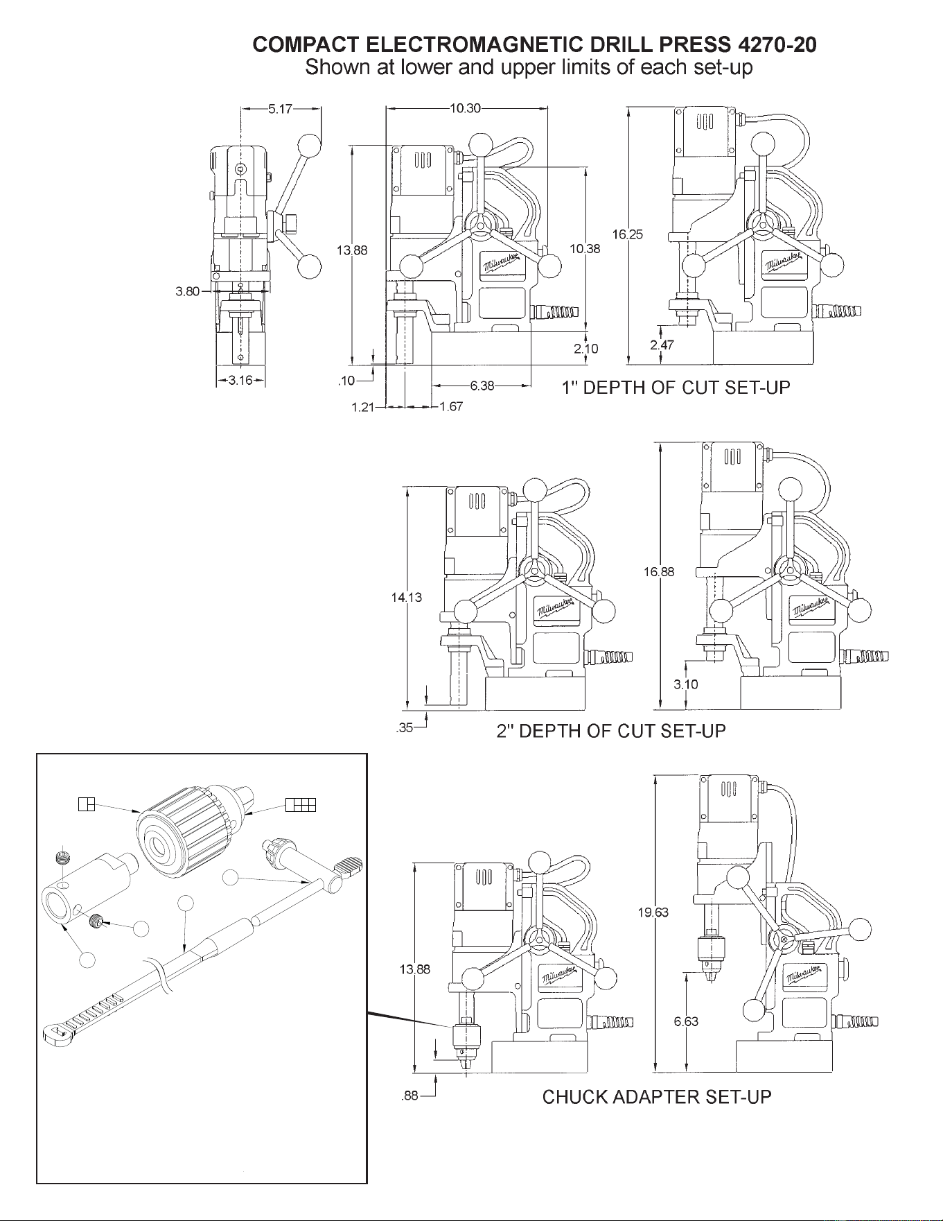
FIG. PART NO. DESCRIPTION OF PART QTY.
1 06-83-6015 5/16-24 x 1/4 Set Screw (2)
2 42-66-0730 Chuck Extension (1)
3 48-66-3280 Chuck Key (1)
4 48-66-4040 Chuck Key Holder (1)
5 48-66-1360 Chuck (1)
6 48-66-2125 Chuck Adapter Kit (1)
49-96-0070 Hex Key (Not Shown) (1)
3
4
2
1
6
1 2 3
4 5
5
3
48-66-2125 Chuck Adapter Kit