Parts List
Number: 71236
Issued: 5-23-2005
Revised: 3-xx-2022
hoshizakiamerica.com
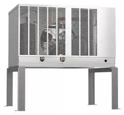
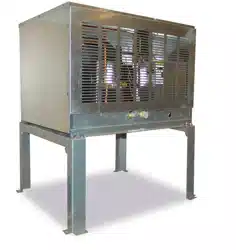
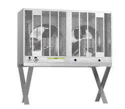
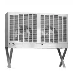
Condensing Unit
Models
SRC-10H

2
CONTENTS
Auxiliary Codes ...................................................................................................................... 3
Note About Ordering Parts .................................................................................................... 3
A. Main Assembly & Refrigeration Circuit .............................................................................. 4
B. Control Box Assembly ........................................................................................................ 6
C. Accessories & Labels ........................................................................................................ 7

3
Auxiliary Codes
SRC-10H
P-0 July 2004
Q-0 July 2005
S-0 February 2007
T-0 April 2008
U-0 January 2009
V-0 January 2010
A-0 January 2011
B-0 January 2012
C-0 January 2013
D-0 January 2014
E-0 May 2015
F-0 March 2016
F-1 May 2016
G-0 February 2017
Auxiliary Code Breakdown
The auxiliary code is the rst two characters in the serial number. The rst character
indicates the year. Years progress or regress in alphabetical order. The series runs from
"A" through "V" and the letters "I" and "O" are skipped. The second character indicates
signicant part changes within a year. Base is "0" and this number advances for each
change. In cases where there is a letter in parentheses, this designates the month. This
is the last character in the serial number. The series runs from "(A)" through "(M)" and the
letter "(I)" is skipped. This designation is only included when identifying a parts change
within an auxiliary code.
Note About Ordering Parts
Most assemblies cannot be ordered as complete units; parts in the assemblies generally
must be ordered separately.
4
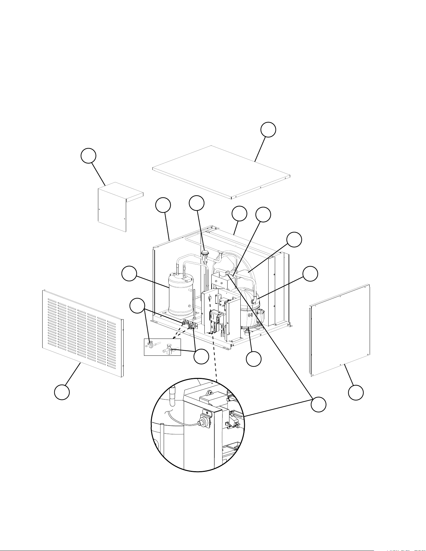
A. Main Assembly & Refrigeration Circuit
SRC-10H
P-0 to G-0
1
2
3
4
5
9
6
7
11
13
14
15
High-Pressure Switch Detail
12
A-0(C) and Earlier
A-0(D) and Later
8
10
F-1 and Later
5
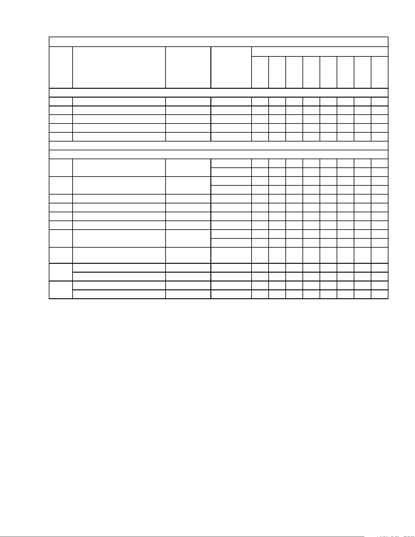
Title: A. Main Assembly & Refrigeration Circuit Model: SRC-10H
Index
No.
Description
Material or
Model Number Part Number
Required Number
P-0
to
A-0
(C)
A-0
(D)
to
C-0
D-0
to
F-0
F-1
G-0
Main Assembly
1 Top Panel 2A3164-01 1 1 1 1
2 Right Side Panel 2A3163-01 1 1 1 1
3 Left side Panel 2A3162-01 1 1 1 1
4 Louver Panel 2A1598-01 1 1 1 1
5 Control Box Cover 3A3182-01 1 1 1 1
Refrigeration Circuit
6 Compressor 4A3494-01 1 1 -
3A6900-02 1 1
7 Crankcase Heater 434186-01 1 1 -
4A5091-01 1 1
8 Condenser 2A1613-01 1 1 1 1
9 Fan Motor 4A3201-01 1 1 1 1
10 Fan Blade 4A1493-01 1 1 1 1
11 Receiver 437652-01 1 1 1 1
12 High-Pressure Switch 433441-05 1 -
463180-04 1 1 1
13 Headmaster (Condensing
Pressure Regulator)
4A0229-03 1 1 1 1
14 Liquid Line Coupling 426554-01 1 1 1 -
Liquid Line Service Valve 4A3491-01 1
15 Suction Line Coupling 434072-01 1 1 1 -
Suction Line Service Valve 4A3490-01 1
6
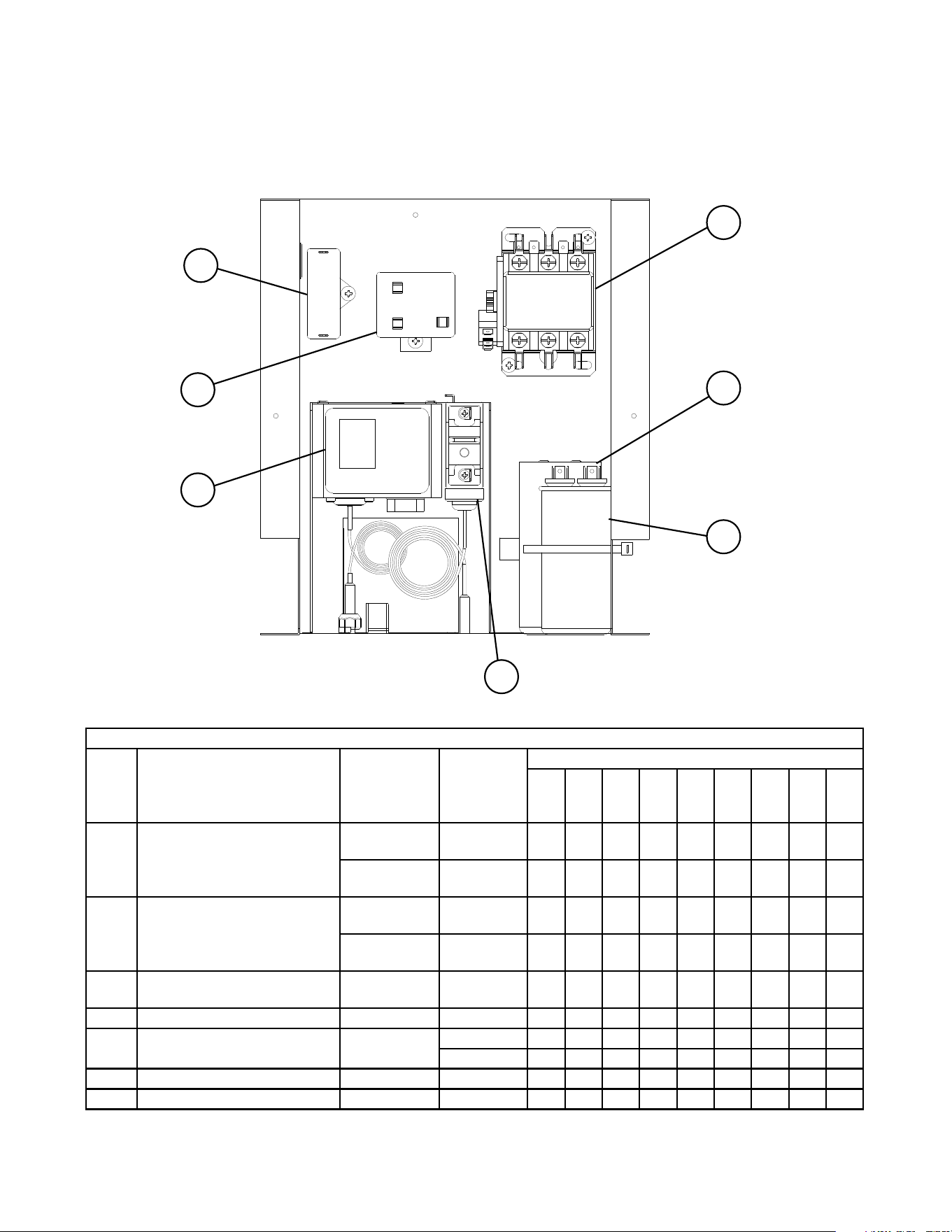
B. Control Box Assembly
SRC-10H
P-0 to G-0
Title: B. Control Box Assembly Model: SRC-10H
Index
No. Description
Material or
Model Number Part Number
Required Number
P-0
to
C-0
D-0
to
G-0
1 Run Capacitor 20MFD,
440VAC
3A2005-01 1 -
30MFD,
440VAC
3A2005-14 1
2 Start Capacitor 189-227MFD,
330VAC
3A0076-12 1 -
108-130MFD,
330VAC
3A0076-22 1
3 Fan Motor Capacitor 10MFD,
250VAC
443192-01 1 1
4 Magnetic Contactor 4A0794-01 1 1
5 Start Relay 4A1107-12 1 -
4A1107-07 1
6 Control Low-Pressure Switch SP-5629 4A5353G01 1 1
7 Safety Low-Pressure Switch 4A3497-01 1 1
3
4
2
1
5
6
7
7
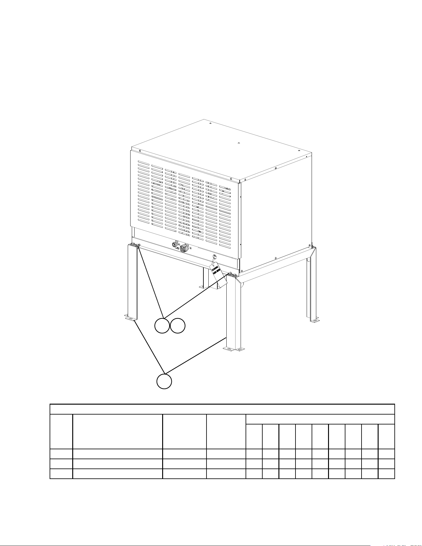
C. Accessories & Labels
SRC-10H
P-0 to G-0
1
1a
1b
Title: C. Accessories & Labels Model: SRC-10H
Index
No. Description
Material or
Model Number Part Number
Required Number
P-0
to
G-0
1 Leg 2A3166G01 2
1a Hex Head Bolt w/ Washer 8×20, SS 7B0130820 8
1b Hex Nut M8, SS 7N12-0800 8