
Part # TG2010
2015-06
Processes
TIG(GTAW) Welding
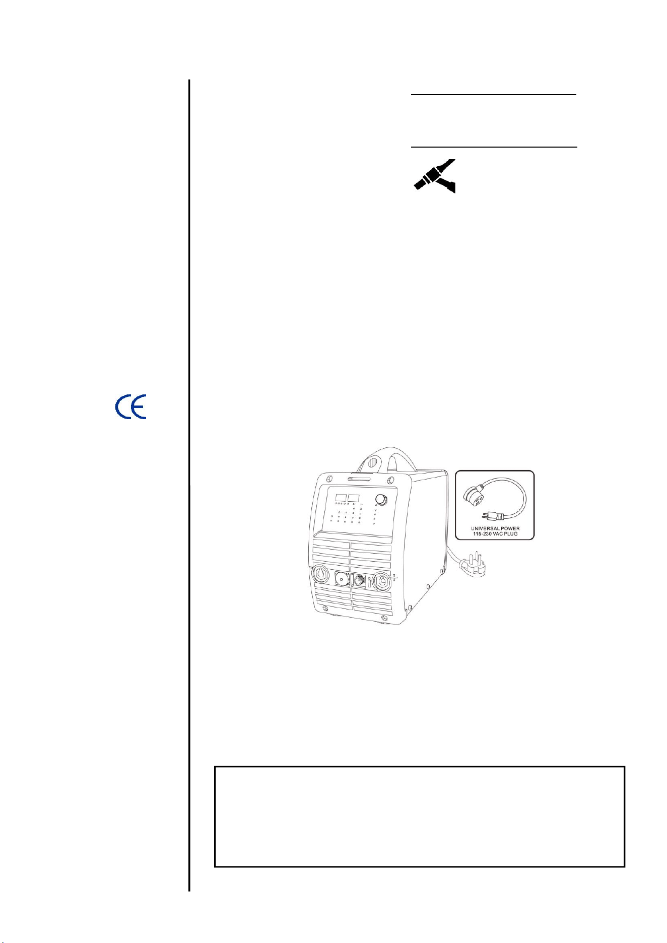
110-240VAC Arc Welding machine
.
2015.06
TG2010 AC/DC PFC
INVERTER AC/DC PULSED TIG WELDER
IMPORTANT: Read this Owner’s Manual Completely before attempting to use this
equipment. Save this manual and keep it handy for quick reference. Pay particular
attention to the safety instructions we have provided for your protection. Contact your
distributor if you do not fully understand this manual.
OPERATOR’S MANUAL

II
CONTENT
SECTION 1: SAFETY ................................................................................................................ 1
1.1 SIGNAL EXPLANATION .......................................................................................................... 1
1.2 ARC WELDING DAMAGE ....................................................................................................... 1
1.3 EXPLANATION OF ELECTRIC AND MAGNETIC FIELDS .............................................................. 4
SECTION 2: INTRODUCTION ................................................................................................... 5
2.1 TG2010AC/DC INFORMATION ......................................................................................... 5
2.2 MODULE EXPLANATION ........................................................................................................ 7
2.3 WORKING PRINCIPLE ........................................................................................................... 7
2.4 VOLT-AMPERE CHARACTERISTIC .......................................................................................... 8
SECTION 3: INSTALLATION AND ADJUSTMENT .................................................................. 9
3.1 PARAMETERS ...................................................................................................................... 9
3.2 DUTY CYCLE & OVER HEAT ................................................................................................ 10
3.3 MOVEMENT AND PLACEMENT .............................................................................................. 10
3.4 POWER SUPPLY INPUT CONNECTION ................................................................................... 11
3.5 MACHINE OPERATIONAL LAYOUT ....................................................................................... 113
3.6 ELECTRODE / TORCH CONNECTIONS .................................................................................... 14
3.7 FOOT PEDAL CONTROL ..................................................................................................... 115
SECTION 4: OPERATION ....................................................................................................... 96
4.1 CONTROL PANEL LAYOUT.................................................................................................. 126
4.2 ARGON ARC WELDING OPERATION ................................................................................... 138
4.2.1 TIG WELDING (4T OPERATION) ................................................................................. 148
4.2.2 TIG WELDING (2T OPERATION) ................................................................................... 19
4.2. TIG WELDING (REPEAT)) .............................................................................................. 20
4.3 SAFE OPERATION .............................................................................................................. 20
4.4 WELDING PARAMETERS ..................................................................................................... 21
4.4.1 JOINT FORMS IN TIG/MMA .......................................................................................... 21
4.4.2 THE EXPLANATION OF WELDING QUALITY ...................................................................... 21
4.4.3 TIG PARAMETERS MATCHING ...................................................................................... 21
4.5 OPERATION ENVIRONMENT ................................................................................................ 24
4.6 OPERATION NOTICES ......................................................................................................... 24
SECTION 5: MAINTENANCE & TROUBLESHOOTING ...................................................... 256
5.1 MAINTENANCE ................................................................................................................. 256
5.2 TROUBLESHOOTING ........................................................................................................... 26
5.3 ELECTRICAL PRINCIPLE DRAWING ....................................................................................... 30
5.4 EXPLODED PARTS LISTING .................................................................................................. 31
5.5 EXPLODED TORCH PARTS LISTING ....................................................................................... 32
OPERATION
1
1 SAFETY
1.1 Signal and Hazard Explanation
The above signals mean Warning, Notice, and Running Parts
Safe operation is simple after taking several necessary protection measures. The protection
measures and hazard explanations are listed in the following pages.
The following pages are meant to prevent most injuries that might occur while welding. While
welding, please remind yourself and others of any danger that that you might be in.
Only trained professionals can install, operate, maintain and repair the welding equipment.
During the operation, only necessary people should be present in the work space.
After shutting off the main power, please remain to examine and maintain the equipment
according to section 5 because of the DC voltage stored in the electrolytic capacitors.
1.2 Arc Welding Damage
ELECTRIC SHOCK CAN KILL.
Never touch electrical parts.
Wear welding-duty safety clothing including hole-free gloves to insulate yourself.
Insulate yourself from other work and the ground by using dry insulation. Make certain the
insulation is large enough to cover your full area of physical contact with work and ground.
Machine should not be operated in wet areas and all cables and hoses should be dry.
Never turn “ON” the machine power before reinstalling covers, guards and cables.
Be sure to install the power cord correctly. Ground the work or metal to be welded with an
earth clamp and be certain that the machine is grounded according to the operation manual.
The electrode and earth circuits are electrically “hot” when the welder is on. Do not touch
these “hot” parts with your bare skin or wet clothing as electrocution may result.
Always be sure the work cable makes a good electrical connection with the metal being
SAFETY
2
welded. The connection should be as close as possible to the area being welded.
Maintain the electrode holder, work clamp, welding cable and welding machine in good, safe
operating condition. Replace any damaged insulation.
Never dip the electrode in water for cooling.
Never simultaneously touch electrically “hot” parts of electrode holders connected to two
welders because voltage between the two can be the total of the voltage of both welders.
When working above ground level in unenclosed areas, use a safety belt to protect yourself
per local codes.
FUMES AND GASES CAN BE DANGEROUS.
Welding may produce fumes and gases hazardous to health. Avoid breathing these fumes
and gases. When welding, keep your head out of the fumes and have enough ventilation near
the arc to keep fumes and gases away from the breathing zone. When welding with electrodes
which require special ventilation such as stainless, hard facing, lead or cadmium plated steel
and other metals or coatings which produce highly toxic fumes, keep exposure as low as
possible and below Threshold Limit Values using local exhaust or mechanical ventilation. In
some instances, specifically when in small spaces, a respirator may be required. Additional
precautions are also required when welding on galvanized steel.
Do not weld in locations near chlorinated hydrocarbon vapors coming from degreasing,
cleaning or spraying operations. The heat and rays of the arc can react with solvent vapors to
form phosgene, a highly toxic gas, and other irritating products.
Shielding gases used for arc welding can displace air and cause injury or death. Always use
enough ventilation, especially in confined areas, to insure breathing air is safe.
Read and understand the manufacturer’s instructions for this equipment and the
consumables, including the material safety data sheet and follow employer’s safety practices.
ARC RAYS CAN BURN AND BLIND.
Use suitable, flame-resistant clothing material to protect your skin from the arc rays.
Protect other nearby personnel with suitable, non-flammable screening and /or warn them not
to watch the arc nor expose themselves to the arc rays.
SAFETY
3
Be careful to avoid hot spatter or metal caused from the arc rays.
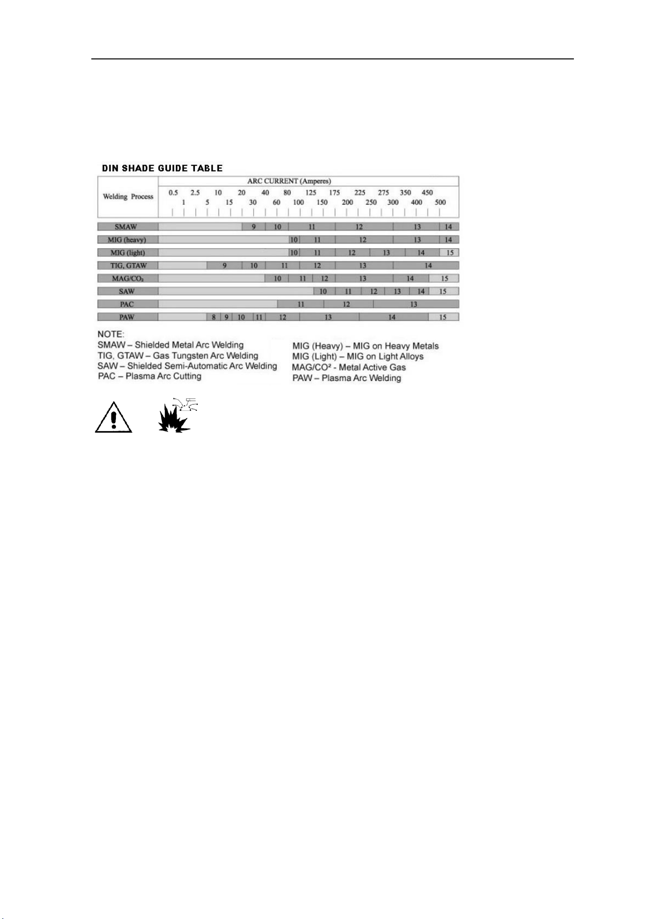
Use a shield with the proper filter and cover plates to protect your eyes from sparks and the
rays of the arc when welding or observing open arc welding.
WELDING SPARKS can cause fire or explosion.
Remove fire hazards from the welding area. If this is not possible, cover them with a
nonflammable material to prevent the welding sparks from starting a fire.
Have a fire extinguisher readily available.
Avoid welding near hydraulic lines as the fluid may be flammable.
Secure all gas cylinders and use only rated regulators and certified hoses.
When not welding, make certain no part of the electrode circuit is touching the work or ground
as accidental contact can cause overheating and create a fire hazard.
Do not heat, cut or weld tanks, drums or containers until the proper steps have been taken to
insure that such procedures will not cause flammable or toxic vapors from substances inside.
They can cause an explosion even though they have been “cleaned”.
Vent hollow castings or containers before heating, cutting or welding to prevent explosions.
Sparks and spatter are thrown from the welding arc. Wear oil free protective garments such
as leather gloves, heavy shirt, cuff less trousers, high closed-toe shoes and a cap over your
hair. Wear ear plugs when welding out of normal position or in confined places. Always wear
safety glasses with correct DIN shading and side shields when in a welding area.

SAFETY
4
Connect the work cable to the work as close to the welding area as practical. Work cables
connected to the building framework or other locations away from the welding area increase
the possibility of the welding current passing through lifting chains, crane cables or other
alternate circuits. This can create fire hazards or overheat lifting chains or cables until they fail.
Gas cylinder safety precautions.
Use only compressed gas cylinders containing the correct shielding gas for the process used
and properly operating regulators designed for the gas and pressure used. All hoses, fittings,
etc. should be suitable for the application and maintained in good condition.
Always keep cylinders in an upright position securely chained to a fixed support.
Cylinders should be located:
- Away from areas where they may be struck or subjected to physical damage.
- A safe distance from arc welding or cutting operations and any source of heat, sparks or
flame.
Never allow the electrode or any other electrically “hot” parts to touch a cylinder.
Keep your head and face away from the cylinder valve outlet when opening the valve.
Valve protection caps should always be securely in place except when the cylinder is in use
or connected for use in secured location.
1.3 Explanation of Electric and Magnetic Fields
Electric current flowing through any conductor causes localized Electro Magnetic Fields
(EMF). The effects of EMF are an ongoing discussion around the world. Up to now, no material
evidence has shown that EMF may have effects on health; however, the research on potential
damage due to EMF is still ongoing. Before any conclusion, all should minimize exposure to
EMF as much as possible by routing cables together (in cable cover if possible), keeping
cables a safe distance from the operator, being sure never to coil around your arms or body,
connecting the LINE power & ground (GRD) correctly and clamping the work cable to the
work-piece as close as possible to the weld area.
Warning: People with heart-pacemaker should be away from the welding operating area.

SUMMARY
5
2 Introduction
2.1 TG2010AC/DC Information
The TG2010 AC/DC TIG welding machine adopts the latest pulse width modulation (PWM)
technology and insulated gate bipolar transistor (IGBT) power module, which can change work
frequency to medium frequency so as to replace the traditional hulking work frequency
transformer with the cabinet medium frequency transformer. Thus, it is known for being
portable, small in size, light weight, and having low consumption.
The parameters of TG2010 on the front panel all can be adjusted with a single control
knob. The parameters include, start current, crater arc current, welding current, base current,
duty ratio, upslope time, downslope time, pre-gas, post-gas, pulse frequency, AC frequency,
balance, hot start, arc force and arc length etc. When welding, it takes high frequency and high
voltage for arc igniting to ensure the success ratio of ignition.
Characteristics:
➢ MCU control system: Responds immediately to any changes.
➢ High frequency & voltage ignition: Ensures the success ratio of igniting arc, the
reverse polarity ignition ensures good ignition behavior for TIG welding.
➢ Break-arc Protection: Avoid arc-break by keeping torch in close proximity to
material; however, if arc-break occurs the HF will keep the arc stable.
➢ Foot pedal control: Provides adjustable welding current for best quality welds.
➢ Tungsten protection: If the tungsten electrode touches the work-piece when DC-TIG
welding, the current will drop automatically to protect tungsten rod.
➢ Intelligent protection: In the event of over-voltage, over-current or over-heating, the
alarm lamp on the front panel will illuminate and the output current will be cut off.
Machine will auto reset when condition has cleared.
➢ Double purpose AC/DC inverter: Excellent performance on Al-alloy、all carbon
steels、stainless steel & titanium.

SUMMARY
6
Machine Welding Functions
⚫ DC MMA (STICK electrode welding for ferrous metals)
⚫ DC TIG (TIG welding for ferrous metals)
⚫ DC Pulse TIG (TIG with pulsed power for welding ferrous metals)
⚫ AC MMA (STICK electrode welding for aluminum metals)
⚫ AC TIG (TIG welding for aluminum metals)
⚫ AC Pulse TIG (TIG with pulsed power for welding aluminum metals)
1. For DC MMA, polarity connection can be chosen according to different electrodes,
please refer to 3.5;
2. For AC MMA, magnetic flow caused by invariable DC polarity can be avoided;
3. For DC TIG, DCEP is normally used (work-piece connected to positive polarity, while
torch connected to negative polarity). This connection has many characters, such as stable
welding arc, low tungsten pole loss, more welding current, narrow and deep weld.
4. For AC TIG Square wave arc is more stable than Sine wave arc. Additionally, you can
not only obtain maximum penetration with the minimum tungsten pole loss, but also obtain
better cleaning effect.
5. For DC TIG Pulsed, see the following characters: 1) Pulse heating. Metal in Molten pool
has short time on high temperature status and freezes quickly, which can reduce the
possibility to produce hot crack of the materials with thermal sensitivity. 2) The work-piece
gets little heat. Arc energy is focused. Suitable for thin sheet and super thin sheet welding.
3) Exactly control heat input and the size of the molten pool. The depth of penetration is
even. Suitable for welding by one side and forming by two sides and all position welding for
pipe. 4) High frequency arc can make metal for microlite fabric, eliminate blowhole and
improve the mechanical performance of the joint. 5) High frequency arc is suitable for high
welding speed to improve the productivity.
SUMMARY
7
TG2010 welding machine is suitable for all positions welding for various plates made of
stainless steel, carbon steel, alloyed steel, titanium, aluminum, magnesium, cuprum, etc. It can
be used for pipe installment, mold mend, petrochemical, architecture design, car repair, bicycle
repair, common manufacturing and more.
2.2 Inverter module explanation
MMA——Manual Metal Arc welding (STICK welding)
PWM——Pulse-Width Modulation (Method of varying output power)
IGBT——Insulation Gate Bipolar Transistor (Fast acting, high power switching)
TIG——Tungsten Insert Gas welding
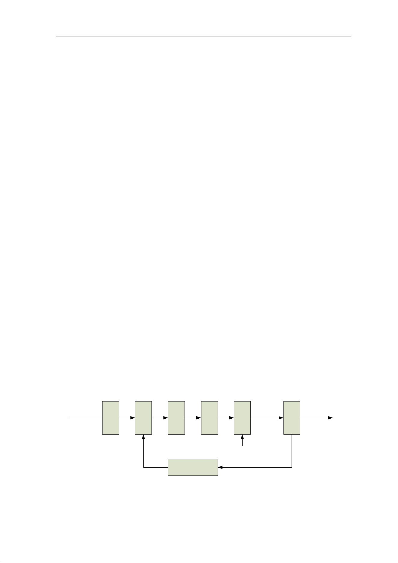
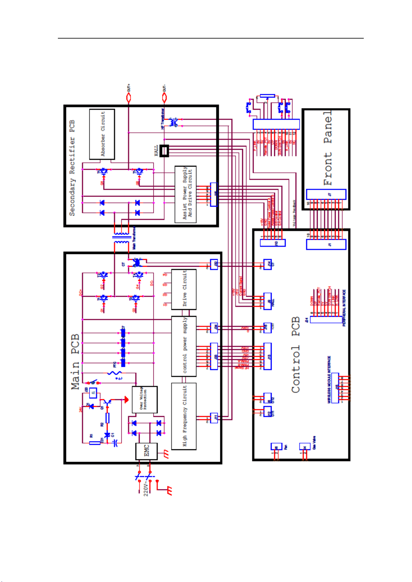
2.3 Working principle
The working principle TG2010 welding machines is shown as the following figure.
Single-phase 110-220V work frequency AC is rectified into DC (about 312V), then is converted
to medium frequency AC (about 20KHz) by inverter device (IGBT module), after reducing
voltage by medium transformer (the main transformer) and rectifying by medium frequency
rectifier (fast recovery diodes), then is outputted DC or AC by selecting IGBT module. The
circuit adopts current feedback control technology to insure stable current output. Meanwhile,
the welding current parameter can be adjusted continuously and infinitely to meet with the
requirements of welding craft.
Rectif
ier
Invert
er
Trans
forme
r
Rectif
ier
Hall
devic
e
Current feedback
control
Single-phase, AC
DC
AC DC
220V,50Hz
AC
Invert
er
AC or DC
Control signal
AC or DC
SUMMARY
8
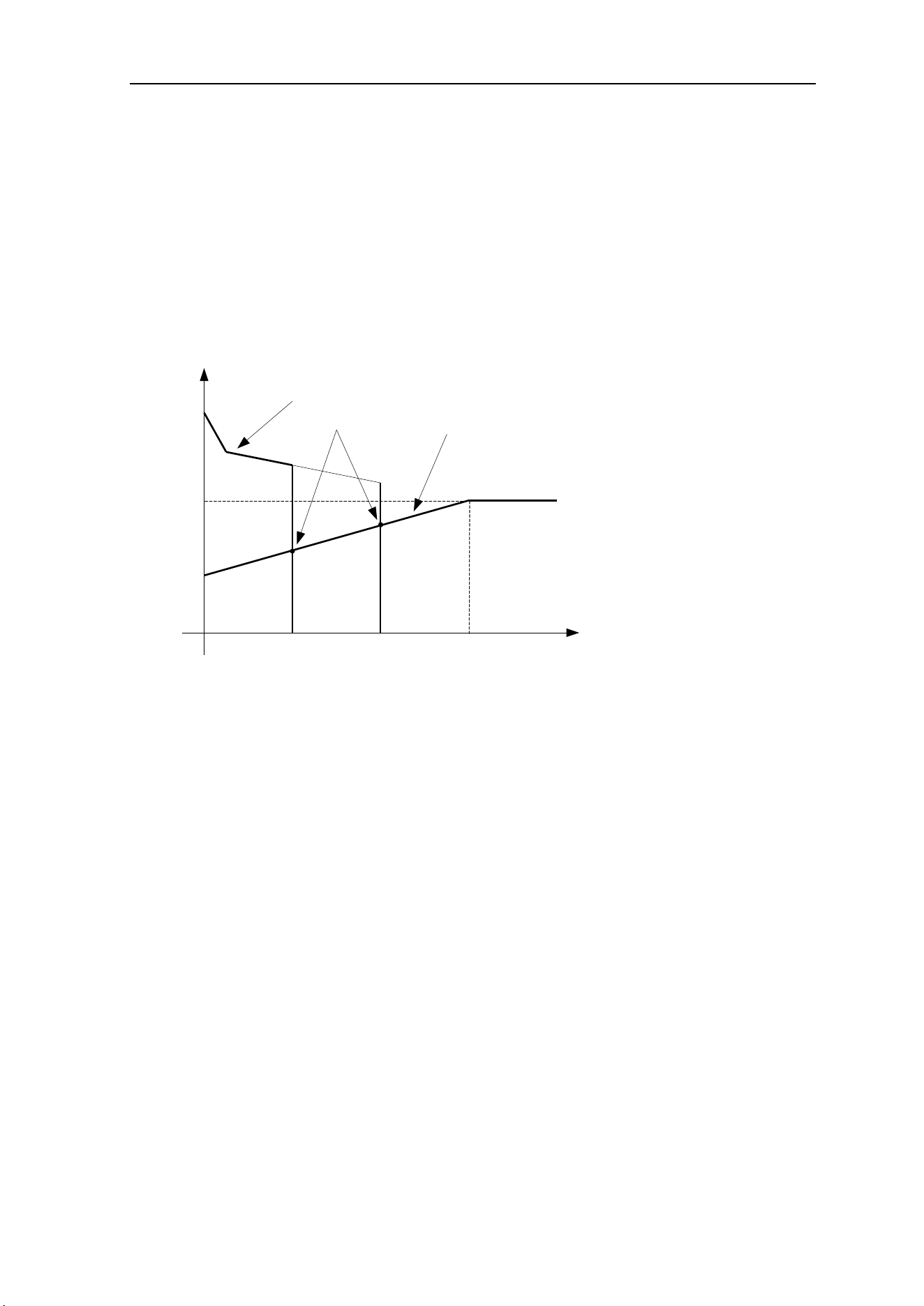
2.4 Volt-Ampere Characteristic
The TG2010 AC/DC welding machine has an excellent volt-ampere characteristic as
shown in the following figure. The relation between the conventional rated loading voltage U
2
and the conventional welding current I
2
is as follows:
When I
2
≤600A,U
2
=10 + 0.04I
2
(V); When I
2
>600A,U
2
=34(V).
67
34
10
0 600
I
2
(A)
U
2
(V)
Working
point
Volt-ampere characteristic
The relation between the
conventional loading
voltage and welding current

OPERATION
9
3 Installation and Adjustment
3.1 Parameters
Mod
els
Parameters
TG2010 AC/DC PFC
Input power
1~220±10%,50Hz
1~110±10%,50Hz
Rated input current
(A)
20/18(AC/DC
TIG)
30/27(AC/DC
MMA)
29/33(AC/DC
TIG)
34/39(AC/DC MMA)
Rated input power
(KW)
4.5/3.9(AC/DC
TIG)
7/5.7(AC/DC
MMA)
3.4/3.7(AC/DC
TIG)
3.8/4.3(AC/DC MMA)
Power factor
0.99
Max-no-load
voltage(V)
67
Start current
adjustment(A)
TIG
MMA
TIG
MMA
AC
DC
AC
DC
AC
DC
AC
DC
5~
welding
current
5~
weldin
g
current
——
——
5~
welding
current
5~
weldin
g
current
——
——
Welding current
adjustment (A)
10~200
5~200
10~
170
5~170
10~
200
5~
200
10~170
5~170
Down slope time
adjustment(S)
0~10
Pre-gas time(S)
0.1~2
Post-gas time
adjustment(S)
0~10
Clearance effect
(%)
20~50
Efficiency
Duty cycle ( 40℃,
10 minutes)
AC
DC
AC
DC
40% 200A
35% 200A
30% 130A
30% 160A
60% 165A
60% 155A
60% 95A
100% 130A
100% 120A
100% 70A
100% 125A
Protection class
IP23
Insulation class
H
Dimensions
(L×W×H)( mm)
510×190×340
Weight(Kg)
14.5
SET-UP, OPERATION & TROUBLSHOOTING
10
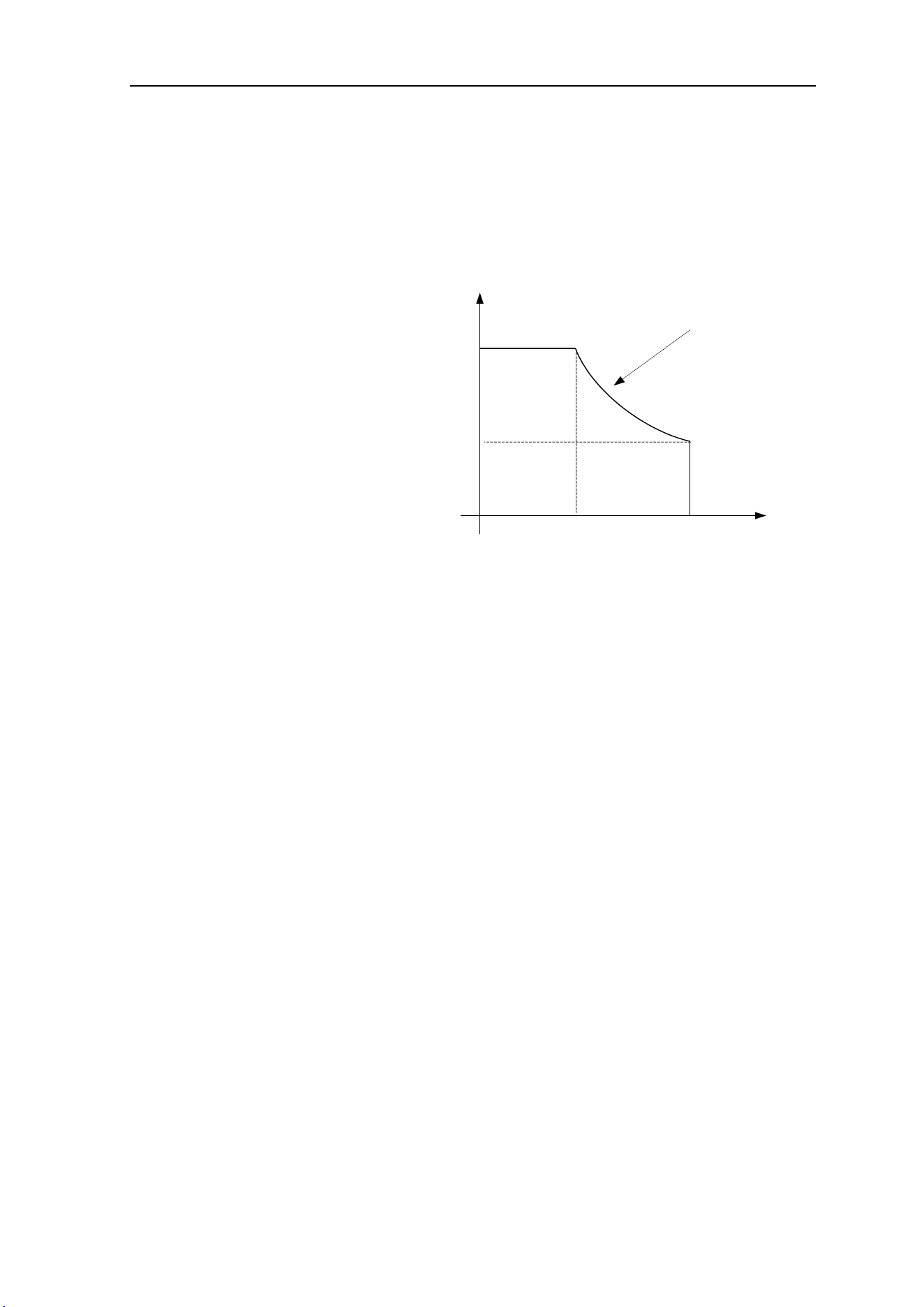
3.2 Duty cycle & over heat
The letter “X” stands for duty cycle, which is defined as the proportion of the time that a
machine can work continuously within a certain time (10 minutes). The rated duty cycle
means the proportion of the time that a
machine can work continuously within 10
minutes at the rated welding current.
The relation between the duty
cycle “X” and the output welding current
“I” is shown as the right figure.
If the welder over-heats due to
operation beyond duty-cycle, the IGBT
over-heat protection will output an instruction to cut output welding current, and brighten the
over-heat pilot lamp on the front panel. If this condition occurs, welding should stop for 10
minutes while the machine cooling fan reduces internal heat. When operating the machine
again, the welding output current or the duty cycle should be reduced so as not to repeat
over-heating condition.
3.3 Movement and placement
Place the welder on a firm surface in horizontal position with all four feet in contact.
Locate machine in dry, clean environment with open-air space for cooling.
Place gas cylinder in upright position and secure in place for safe operation.
Make sure that all cables and torches are in a safe position before using welder.
Ensure all electrical and grounding connections are secure per local codes.
Safety shields and curtains should be used to protect other personnel in shop.
I(A)
0
100%
25%
100 200
X
The relation of the welding current and
duty cycle for WSME-200
35%
SET-UP, OPERATION & TROUBLSHOOTING
11
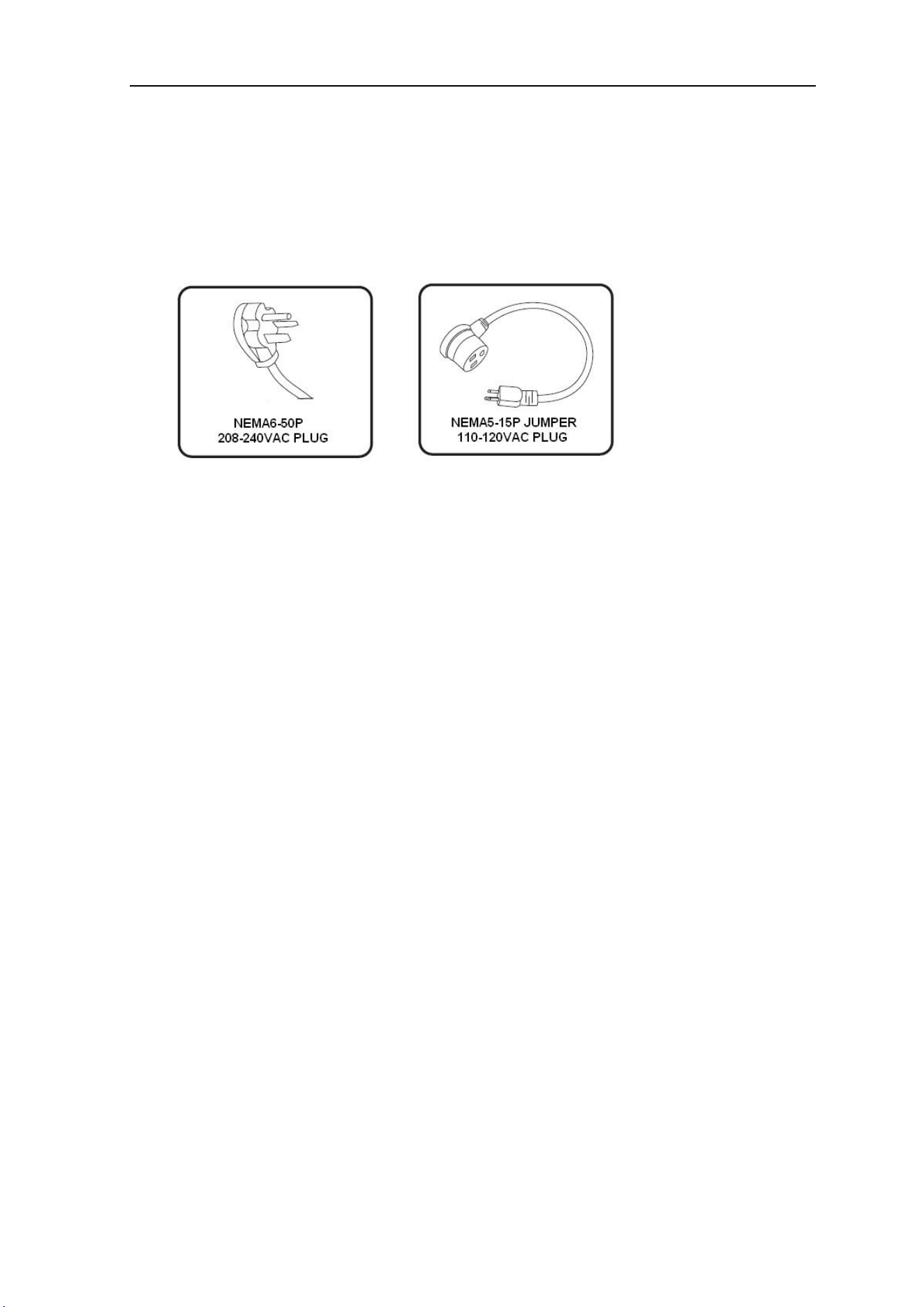
3.4 Power supply input connection
The TG2010 AC/DC PULSE PFC welding machine features electronic switching power
supply allowing it to be connected to any 115-240VAC, 1-Phase LINE power outlet.
208-240VAC LINE CONNECTION: Machine is provided with NEMA 6-50P LINE Service
cord to be plugged into any 6-50R outlet with 208-240VAC, single-phase power and 50-amp
circuit breaker.
110-120VAC LINE CONNECTION: Machine is provided with NEMA 6-50R to NEMA
5-15P “Jumper” Service cord. This allows machine to be plugged into any 5-15R standard
outlet with 110-120VAC, single-phase power and 20-amp circuit breaker.
In the event NEMA6-50R or 5-15R outlets, with rated LINE circuit breaker
amperage are not available, they should be installed by a licensed electrician in
accordance to all national & local codes.
In the event LINE power supply is over voltage (>245) or under voltage (<195),
protection circuit inside the machine will illuminate alarm light and current will be cut off.
If the power supply voltage continually goes beyond the safe work voltage range, it will
shorten the life of the machine. If this occurs, the below measures should be taken:
⚫ Change the LINE power supply. Such as, connect the welder to a dedicated circuit.
⚫ Shut off other machines using LINE power supply at the same time as welding.
WARNING: Any modification or removal of factory installed service power cords
will VOID MACHINE WARRANTY!
SET-UP, OPERATION & TROUBLSHOOTING
12
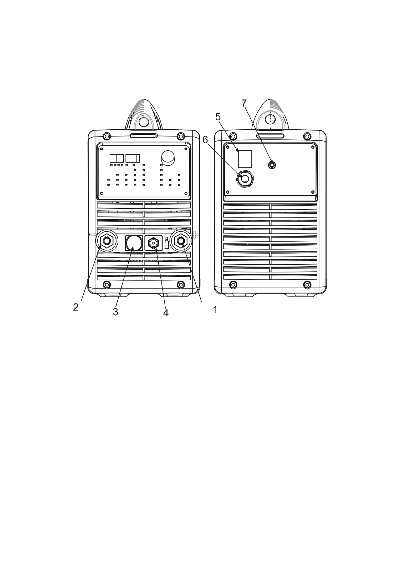
3.5 Machine operational layout
1 Positive output: Socket with positive polarity output.
2 Negative output: Socket with negative polarity output.
3 Control output: Socket to torch or foot pedal control wire.(Lead 8 - lead 9 are trigger)
4 Shield gas output: Brass male fitting to connect gas input hose of torch.
5 Power switch: Controls input power ON/OFF to the welding machine
6 Power source input: Power cord service cable with input power plug
7 Shield gas input: Brass male fitting to connect gas hose from shield gas cylinder.
SET-UP, OPERATION & TROUBLSHOOTING
13
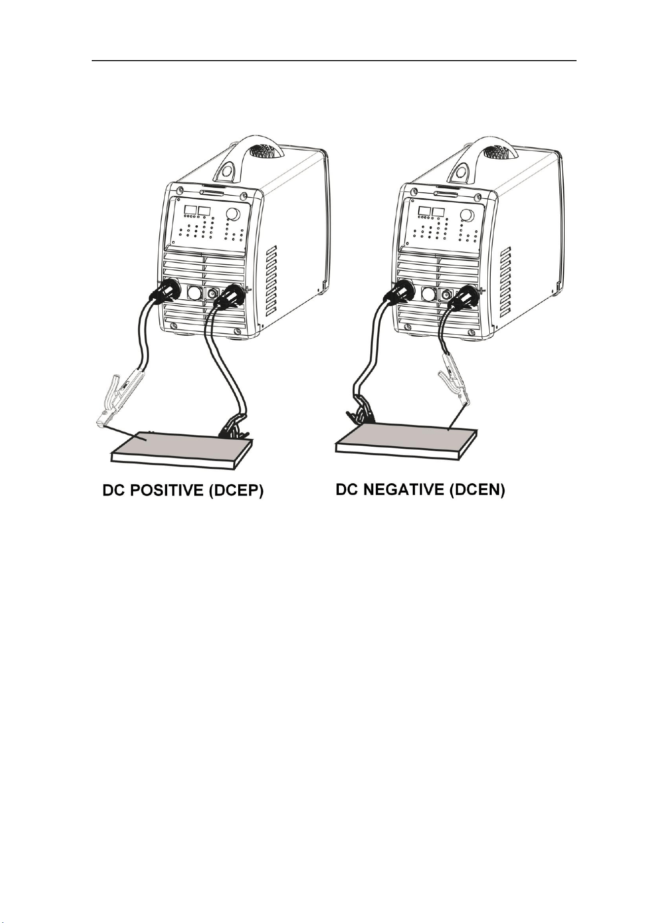
3.6 Electrode / Torch polarity connections(MMA)
⚫ DC POSITIVE CONNECTION (DCEP): Work-piece is connected to the positive (+)
socket of welding machine, and welding torch is connected to the negative (-) socket.
Most common TIG and MMA (Stick) welding connection: Torch to negative (-)
⚫ DC NEGATIVE CONNECTION (DCEN): Work-piece is connected to the negative (-)
socket of welding machine, and welding torch is connected to the positive (+) socket.
⚫ CONTROL CABLE SOCKET: Torch or foot pedal control plug with12 pins.
⚫ GAS LINE CONNECT: Gas hose from welding torch connects for automatic operation.
⚫ TIG TORCH CONSUMABLES: Refer to TIG torch parts breakdown
⚫ WARNING: Use of HF ignition can cause interferences in equipment near the
welding machine. Be sure to take safety precautions or shielding measures.
SET-UP, OPERATION & TROUBLSHOOTING
14
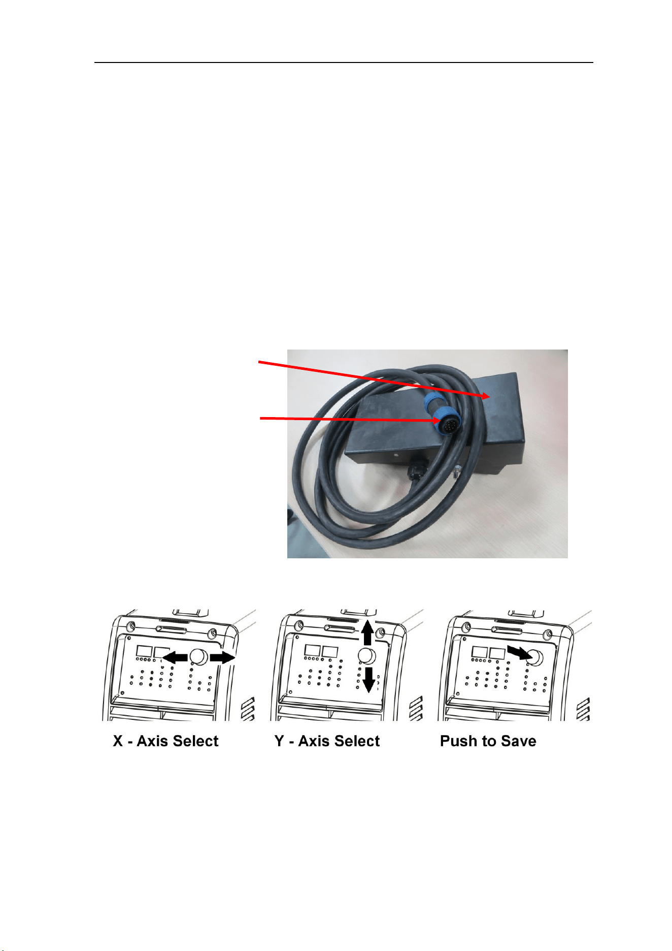
3.7 Foot pedal switch control
● Once the foot pedal cable is inserted into control-socket on front panel of welder, it will
identify the pedal switch. Only 2T/4T modes should be selected when foot pedal operation is
desired.
● Adjustment knob on side of the pedal will set the maximum output current desired for
application allowing pedal to be pushed fully down to desired maximum current.
● Pins #7 & #8 on control-socket are trigger contacts. Pins #1 & #2 are contact closure
(trigger) and pins #3, #4, & #5 are for adjustable resistance to control output power.
3.8 Control knob functions
TOGGLE TO SELECT various machine processes and functions (X & Y axis)
TURN TO SET operational levels (Clockwise + & Counter-Clockwise -)
PUSH TO SAVE settings to various stored JOB programs.
Connected to control
socket on the front
panel
Foot pedal adjustment
of welding curren
OPERATION
15
4 Operation
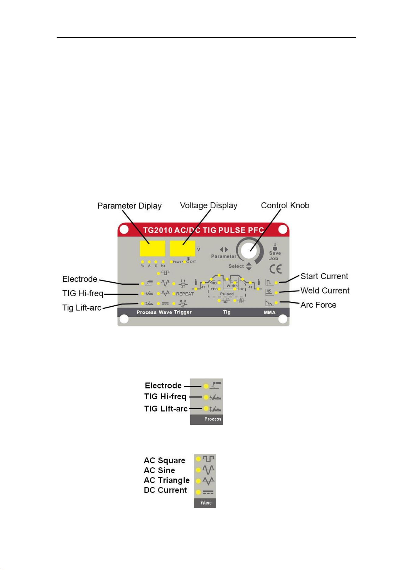
4.1 Control panel layout
The key feature of the control panel is the logical way in which the controls are arranged. All the
main parameters needed for operation are easily selected and adjusted to welding application.
Once parameters for a particular welding JOB have been set, push to save in memory to recall.
The illustration below shows an overview of the TG2010 control panel as an example. You will
find a detailed description of these settings in the following section.
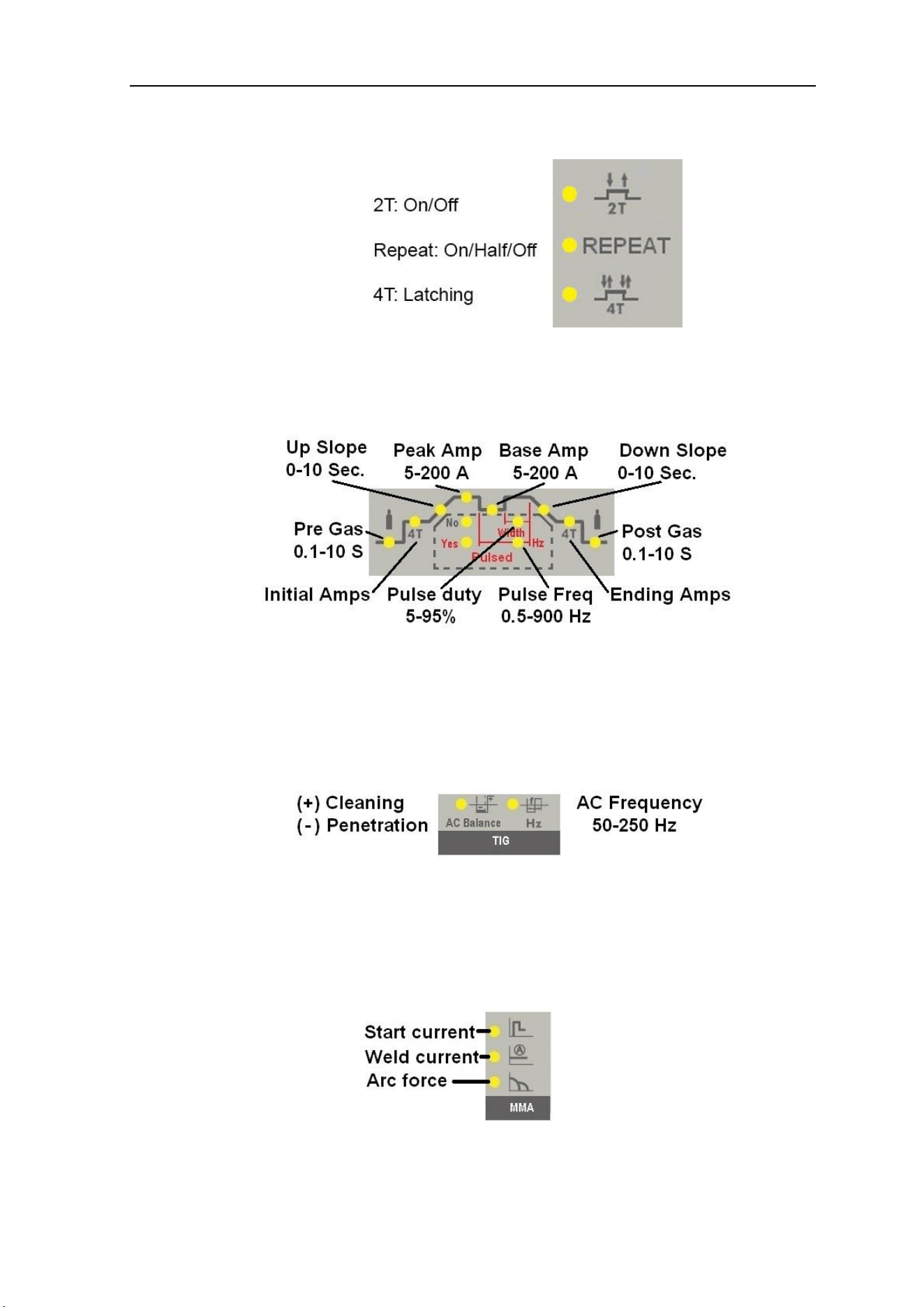
(1) MMA (Stick), TIG with HF ignition or TIG with LIFT-ARC ignition process selection
(2) AC / DC output current and wave form selection
SET-UP, OPERATION & TROUBLSHOOTING
16
(3) Trigger mode selection (TIG only)
(4) TIG parameter settings
(5) AC parameter settings
(6) MMA stick electrode parameter settings
SET-UP, OPERATION & TROUBLSHOOTING
17
4.2 Argon Arc Welding Operation
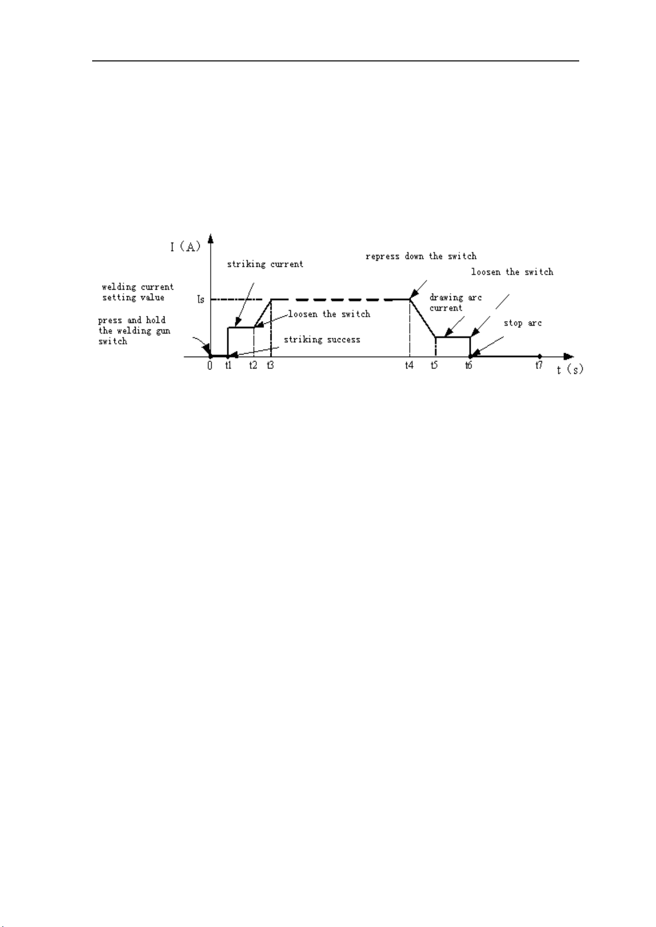
4.2.1 TIG welding(4T operation)
The START and END current and can be pre-set to compensate for crater that
appears at the beginning and end of the welding making 4T ideal for aluminum and
medium thickness plates.
Process:
⚫ 0: Press down and hold the pedal switch, gas valve is opened.
⚫ 0~t1: Pre-gas flows at preset time (0.1~1S);
⚫ t1~t2: Arc is ignited at t1 and output is at preset value of start current;
⚫ t2: Release pedal switch, the output current slopes up from the start current;
⚫ t2~t3: The output current rises to the setting value (Iw or Ib), per upslope time set;
⚫ t3~t4: Welding process. During this period, the pedal switch is UP;
Note: Select the pulsed output, the base current and welding current will be outputted
alternately; otherwise, output the setting value of welding current;
⚫ t4: Press the pedal switch DOWN and the welding current will drop per the selected
down-slope time to end current setting;
⚫ t4~t5: The output current slopes down to the end crater current setting
⚫ t5~t6: The crater current time (controlled by pedal);
⚫ t6: Release pedal switch to stop arc but keep shield gas flowing;
⚫ t6~t7: Post-gas time(0.1~10S)until valve closes;
⚫ t7: Gas valve is closed and welding process is finished.
OPERATION
18
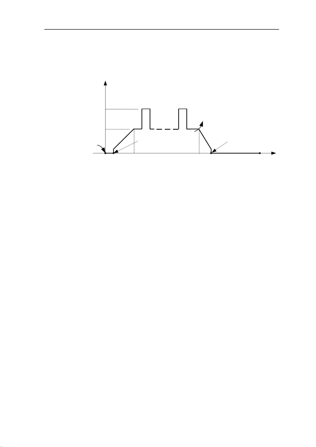
4.2.2 TIG welding (2T operation)
This function, without the adjustment of start current and crater current, is ideal for
tack welding、transient welding and thin plate welding.
t(s)
0
I(A)
Loosen the
welding gun
switch
Press and hold the welding
gun switch
t1 t4 t5
Arc is
ignited
Arc is
turned off
t2 t3
Welding current Is
The setting base
current Ib
Process:
⚫ 0: Press the gun switch and hold it. Electromagnetic gas valve is turned on. The
shielding gas stars to flow.
⚫ 0~t1: Pre-gas time (0.1~1s)
⚫ t1~t2: Arc is ignited and the output current rises to the setting welding current (Iw or Ib)
from the min welding current.
⚫ t2~t3: During the whole welding process, the gun switch is pressed and held without
releasing.
Note: Select the pulsed output, the base current and welding current will be outputted
alternately; otherwise, output the setting value of welding current;
⚫ t3: Release the gun switch, the welding current will drop in accordance with the
selected down-slope time.
⚫ t3~t4: The current drops to the minimum welding current from the setting current (Iw or
Ib), and then arc is turned off.
⚫ t4~t5: Post-gas time, after the arc is turned off. You can adjust it (0.1~10s) through
turning the knob on the front panel.
⚫ t5: electromagnetic gas valve turned off, the shield gas stops to flow, and welding is
finished.

SET-UP, OPERATION & TROUBLSHOOTING
19
4.2.3 TIG welding (Repeat)
This function only works with a triggered gun; it will not function with foot pedal.
This welding mode is ideal for working back and forth between two metals of varying
characteristics. (Thick and thin, wide or narrow seam, deep or flat, etc.)
• This function allows the user to have easy access to two levels of current when
using a triggered gun. Set repeat current to 1/2 or 1/3 of the MAIN welding current.
The current will drop to this setting when trigger is released.
• Start by pulling the trigger. When the trigger is held, the original set current will go
across the metal. When the trigger is released the first time, the current will drop by
the fraction previously set. When the trigger is held again, back to original current.
• Example: Current is set to 160amps and the repeat setting is set to 1/2. The trigger
is held and the arc flows at 160amps. The welder gets to a thinner section of metal.
By releasing the trigger, the amps drop to 80amps (1/2 of 160amps) and the welder
continues. By pressing the trigger again, the current returns to 160 amps.
4.3 Safe Operation
Short circuit protect function:
1. TIG /DC/LIFT:If the tungsten electrode touches the work-piece when welding, the
current will drop to 20A, which can reduce the tungsten damage, prolong the life of the
tungsten electrode and prevent tungsten clipping.
2. TIG /DC/HF:If the tungsten electrode touches the work-piece when welding, the
current will drop to 0 within 1s, which can reduce the tungsten damage, prolong the life
of the tungsten electrode and prevent tungsten clipping.
3. MMA operation: If the electrode touches work-piece over two seconds, the welding
current will drop to the 0 automatically to protect the electrode.
4. TIG:If the TIG torch is pressed quickly, the welding current will drop a half, then if the
TIG torch is pressed quickly again, the welding current will return to preset level.

SET-UP, OPERATION & TROUBLSHOOTING
20
Torch & earth clamp checklist:
⚫ Check welding cable machine connections are twist-locked in place and gas fittings are
secure; otherwise there may be malfunction such as ignition spark, gas leakage, and
unstable arc.
⚫ Check that there is enough shield gas in the cylinder and that regulator is set correctly, you
can test the electromagnetic gas valve through the switch on the front panel.
⚫ Do not aim torch at your hand or anywhere on your body. When you press the torch switch,
the arc is ignited with a high-frequency, high-voltage spark. The ignition spark can burns.
⚫ The shield gas flow rate is set according to the welding power used in the job. Turn the
regulation screw to adjust to the desired gas flow required for the application.
⚫ The HF ignition works better if you keep 3mm (1/8”) distance from the work-piece to the
tungsten electrode during the ignition.
Note: When the AC output is selected, the settings are as same as the above, but output
polarity changes.

SET-UP, OPERATION & TROUBLSHOOTING
21
4.4 Welding Parameters
4.4.1 Joint forms in TIG/MMA
4.4.2 The explanation of welding quality
The relation of welding area color & protect effect of stainless steel
Welding area
color
argent ,
golden
blue
red-grey
grey
black
Protect effect
best
better
good
bad
very bad
The relation of welding area color & protect effect of Ti-alloy
Welding area
color
bright argent
orange-yello
w
blue-purpl
e
dark blue
white powder
of titanium
oxide
Protect effect
best
better
good
bad
very bad
4.4.3 TIG Parameters Matching
The corresponding relationship between gas nozzle diameter and electrode
diameter
Gas nozzle diameter/mm
Electrode diameter/mm
6.4
0.5
8
1.0
9.5
1.6 or 2.4
11.1
3.2
Notice: the above parameters originate from《Welding Dictionary》P142, Volume 1
of Edition 2.
a butt joint
b lap joint c coner joint d T joint

SET-UP, OPERATION & TROUBLSHOOTING
22
Gas nozzle and the shield gas flow rate
Welding current
range/A
DC positive connection
AC
Gas nozzle
diameter/mm
Gas flow
rate/L·min
-1
Gas nozzle
diameter/mm
Gas flow
rate/L·min
-1
10~100
4~9.5
4~5
8~9.5
6~8
101~150
4~9.5
4~7
9.5~11
7~10
151~200
6~13
6~8
11~13
7~10
201~300
8~13
8~9
13~16
8~15
Notice: the above parameters originate from《Welding Dictionary》P149, Volume 1 of Edition 2.
tungsten electrode
diameter /mm
sharpened of the
electrode
diameter/mm
angle of cone(°)
background current/A
1.0
0.125
12
2~15
1.0
0.25
20
5~30
1.6
0.5
25
8~50
1.6
0.8
30
10~70
2.4
0.8
35
12~90
2.4
1.1
45
15~150
3.2
1.1
60
20~200
TIG of stainless steel (single run welding)
Work piece
thickness
/mm
Joint form
tungsten
electrode
diameter/m
m
welding
wire
diameter/m
m
Argon gas
flow rate/
L·min
-1
welding
current
(DCEP)
Welding
speed/
cm·min
-1
0.8
Butt joint
1.0
1.6
5
20~50
66
1.0
Butt joint
1.6
1.6
5
50~80
56
1.5
Butt joint
1.6
1.6
7
65~105
30
1.5
Corner
joint
1.6
1.6
7
75~125
25
2.4
Butt joint
1.6
2.4
7
85~125
30
2.4
Corner
joint
1.6
2.4
7
95~135
25
3.2
Butt joint
1.6
2.4
7
100~135
30

SET-UP, OPERATION & TROUBLSHOOTING
23
3.2
Corner
joint
1.6
2.4
7
115~145
25
4.8
Butt joint
2.4
3.2
8
150~225
25
4.8
Corner
joint
3.2
3.2
9
175~250
20
Notice: the above parameters originate from《Welding Dictionary》P150, Volume 1 of Edition 2.
Parameters of AC TIG (MMA) for Aluminum and its alloy
Sheet
thicknes
s
/mm
Weldin
g wire
diamet
er
/mm
Tungste
n
electrod
e
diamete
r
/mm
Pre-he
at
Tempe
r
-ature
/℃
Weldin
g
current
/A
Argon
flow
rate
/ L·min
-1
Gas
nozzle
diamet
er
/mm
Remark
1
1.6
2
-
45~60
7~9
8
Flange welding
1.5
1.6~2.0
2
-
50~80
7~9
8
Flange or butt
welding by one
side
2
2~2.5
2~3
-
90~120
8~12
8~12
Butt welding
Parameters of piping back sealing welding for mild steel(DCEP)
Piping
diamet
erΦ/m
m
Tungsten
electrode
diameter/m
m
Gas nozzle
diameter/m
m
Welding
wire
diameter/m
m
Welding
current/
A
Arc
voltage/
V
Argon
flow
rate
/ L·min
-1
Welding
rate
/
cm·min
-1
38
2.0
8
2
75~90
11~13
6~8
4~5
42
2.0
8
2
75~95
11~13
6~8
4~5
60
2.0
8
2
75~100
11~13
7~9
4~5
76
2.5
8~10
2.5
80~105
14~16
8~10
4~5
108
2.5
8~10
2.5
90~110
14~16
9~11
5~6
133
2.5
8~10
2.5
90~115
14~16
10~12
5~6
159
2.5
8~10
2.5
95~120
14~16
11~13
5~6
219
2.5
8~10
2.5
100~
120
14~16
12~14
5~6
273
2.5
8~10
2.5
110~
125
14~16
12~14
5~6
325
2.5
8~10
2.5
120~
140
14~16
12~14
5~6
Notice: the above parameters originate from《Welding Dictionary》P167, Volume 1 of Edition 2.

SET-UP, OPERATION & TROUBLSHOOTING
24
3
2~3
3
-
150~
180
8~12
8~12
V-groove butt
welding
4
3
4
-
180~
200
10~15
8~12
5
3~4
4
-
180~
240
10~15
10~12
6
4
5
-
240~
280
16~20
14~16
8
4~5
5
100
260~
320
16~20
14~16
10
4~5
5
100~
150
280~
340
16~20
14~16
12
4~5
5~6
150~
200
300~
360
18~22
16~20
14
5~6
5~6
180~
200
340~
380
20~24
16~20
16
5~6
6
200~
220
340~
380
20~24
16~20
18
5~6
6
200~
240
360~
400
25~30
16~20
20
5~6
6
200~
260
360~
400
25~30
20~22
16~20
5~6
6
200~
260
300~
380
25~30
16~20
X-groove butt
welding
22~25
5~6
6~7
200~
260
360~
400
30~35
20~22
Notice: the above parameters originate from《Welding Dictionary》P538, Volume 2 of Edition 2.
4.5 Operation Environment
● Operation temperature range: 14
0
F - 104
0
F (-10
0
C~+40
0
C)
● Relative humidity should be below 90 %.
● Machine placement: horizontal bench or cart to maximum angle does not exceed 15
0
.
● Protect the machine against heavy rain or in hot circumstance against direct sunshine.
● Sufficient ventilation of at least 1’ (30cm) free space between the machine and wall.
4.6 Operation Notices
● Read section 1 carefully before attempting to use this equipment.
● Connect the ground wire with the machine directly, and refer to section 3.5
● When the power switch shuts off protectively, don’t restart it until problem is resolved.

SET-UP, OPERATION & TROUBLSHOOTING
25
5 Maintenance & Troubleshooting
5.1 Maintenance
In order to guarantee that arc welding machine works high-efficiently and in safety, it must
be maintained regularly so as to lengthen service life of arc welding machine. Maintenance
items in detail are in the following table.
● Warning: For safety while maintaining the machine, please shut off the supply power
and wait for 5 minutes or until capacitor voltage drops to safe level below 36V!
date
Maintenance item
Daily exam
Observe whether the panel knob and switch in the front and at the back of arc
welding machine are flexible and put correctly in place. If the knob has not been put
correctly in place, please correct; If you can't correct or fix the knob , please replace
immediately;
If the switch is not flexible or it can't be put correctly in place, please replace
immediately; Please get in touch with maintenance service department if there are
no accessories.
After turning-on power, watch/listen to see whether the arc welding machine is
shaking, whistling or has a peculiar smell. If one of the above problems exists, find
out the reason and correct it. If you can't find out the reason, please contact your
dealer or the factory.
Observe whether the display value of LED is intact. If the display number is not
intact, please replace the damaged LED. If it still doesn’t work, please maintain or
replace the display PCB.
Observe whether the min/max value on LED accords with the set value. If there
are any differences and it is affecting the normal welding craft, please adjust it.
Check that the cooling fan is not damaged and is in normal and working condition.
If the fan is damaged, please change immediately. If the fan does not rotate, look to
see if there is something blocked in the blade. If it is blocked, remove it cautiously. If
the fan does not rotate after fixing the above problems but starts when blade is
pushed in the direction of fan, the start capacitor should be replaced. If not, replace
the fan.
Check if torch power and/or ground cable connectors are loose or show signs of
overheating. If this is observed, they should be fastened or changed.
Check whether the current output cable is damaged. If it is damaged, it should be

SET-UP, OPERATION & TROUBLSHOOTING
26
wrapped up, insulated or changed.
Monthly
exam
Use dry compressed air to clean and remove dusts on radiator, main voltage
transformer, inductance coils, IGBT module, the fast recover diodes and PCB’s.
Check the cable lugs on arc welding machine, if loose, please screw down
securely. If burnt, please replace. If it is rusty, please remove rust on bolt & washer
for good contact.
Quarter-
yearly
exam
Check whether the actual current accords with the displaying value. If they do not
match, they should be regulated. The actual current value can be measured by the
adjusted plier-type ampere meter.
Yearly
exam
Measure the insulating impedance among the main circuit, PCB and case, if it
below 1MΩ, insulation is thought to be damaged and need to change or strengthen
insulation.
5.2 Troubleshooting
⚫ Before arc welding machines are dispatched from the factory, they have already been
debugged accurately. So do not allow anyone who is not authorized by the factory to make
any changes to the equipment!
⚫ Maintenance course must be operated carefully. If any wire becomes flexible or is
misplaced, it maybe potential danger to User!
⚫ Only professional maintenance personnel authorized by factory should repair the machine!
⚫ Guarantee to shut off machine’s LINE power before any maintenance of the equipment!
If there are some simple problems, consult the following trouble-shooting chart:
S/N
Troubles
Reasons
Solution
1
Turn on the power source,
and fan works, but the power
pilot lamp is not on.
The power light damaged or connection
is not good
Check and repair Pr7
The transformer of power is broken
Repair or change the transformer
Control PCB failures
Repair or change the control Pr4
2
Turn on the power source,
and the power lamp is on, but
There is something in the fan
Clear out
The start capacitor of fan damaged
Change capacitor

SET-UP, OPERATION & TROUBLSHOOTING
27
S/N
Troubles
Reasons
Solution
fan doesn’t work
The fan motor damaged
Change fan
3
Turn on the power source, the
power lamp is not on, and fan
doesn’t work
No power supply input
Check whether there is power supply
The fuse inside the machine damaged
Change it (3A)
4
The number on the display is
not intact.
The LED in the display is broken
Change the LED
5
The max and min value
displayed doesn’t accord
with the set value.
The max value is not accordant (refer to
§3.1)
Adjust potentiometer Imin on the
power board.
The min value is not accordant (refer to
§3.1)
Adjust potentiometer Imaxin the
current meter.
6
No no-load voltage output
(MMA)
The machine is damaged
Check the main circuit and the Pr4.
7
Arc can not
be ignited
(TIG)
There is
spark on the
HF igniting
board.
The welding cable is not connected with
the two output of the welder.
Connect the welding cable to the
welder’s output.
The welding cable damaged.
Repair or change it.
The earth cable connected unstably.
Check the earth cable.
The welding cable is too long.
Use an appropriate welding cable.
There is oil or dust on the work-piece.
Check and remove it.
The distance between tungsten electrode
and work-piece is too long.
Reduce the distance (about 3mm).
There is not
spark on the
HF igniting
board.
The HF igniting board does not work.
Repair or change Pr8
The distance between the discharger is
too short.
Adjust this distance (about 0.7mm).
The malfunction of the welding gun
switch.
Check the welding gun switch,
control cable and aero socket.
8
No gas flow (TIG)
Gas cylinder is close or gas pressure is
low
Open or change the gas cylinder
Something in the valve
Remove it
Electromagnetic valve is damaged
Change it
9
Gas always flows
The gas-test on the front panel is on
The gas-test on the front panel is off
Something in the valve
Remove it
Electromagnetic valve is damaged
Change it
The adjustment knob of pre-gas time on
the front panel is damaged
Repair or change it
10
The welding current cannot
be adjusted
The welding current potentiometer on the
front panel connection is not good or
damaged
Repair or change the potentiometer
11
No AC output while selecting
“AC”
The power PCB is in trouble.
Repair or change it.
The AC drive PCB damaged.
Change it.
The AC IGBT module damaged.
Change it.

SET-UP, OPERATION & TROUBLSHOOTING
28
S/N
Troubles
Reasons
Solution
12
The welding current displayed
isn’t accordant with the actual
value.
The min value displayed isn’t accordant
with the actual value. (Please refer to
§3.1)
Adjust potentiometer Imin on the
power board.
The max value displayed isn’t accordant
with the actual value. (Please refer to
§3.1)
Adjust potentiometer Imax on the
power board.
13
The penetration of molten
pool is not enough.
The welding current is adjusted too low
Increase the welding current
The arc is too long in the welding process
Use 2T operation
14
The alarm lamp on the front
panel is on
Over heat
protection
Two much welding
current
Reduce the welding current output
Working time too
long
Reduce the duty cycle (work
intermittently)
Over-voltage
protection
Power supply
fluctuates
Using the stable power supply
Low-voltage
protection
Power supply
fluctuates
Using the stable power supply
Too many
machines using
power supply in the
same time
Reduce the machines using power
supply in the same time
Over-current
protection
Unusual current in
the main circuit
Check and repair the main circuit and
drive Pr6
SET-UP, OPERATION & TROUBLSHOOTING
29
5.3 Electrical principle drawing
PARTS & SERVICE
30
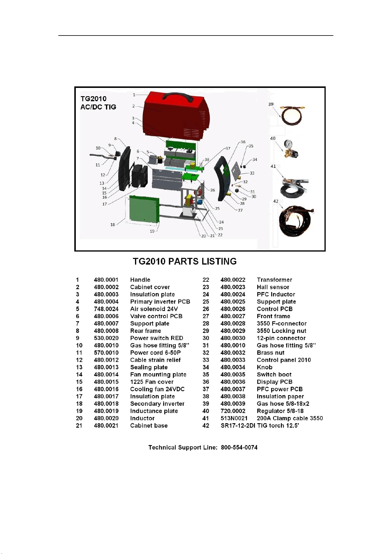
5.4 Exploded Parts Listing
PARTS & SERVICE
31
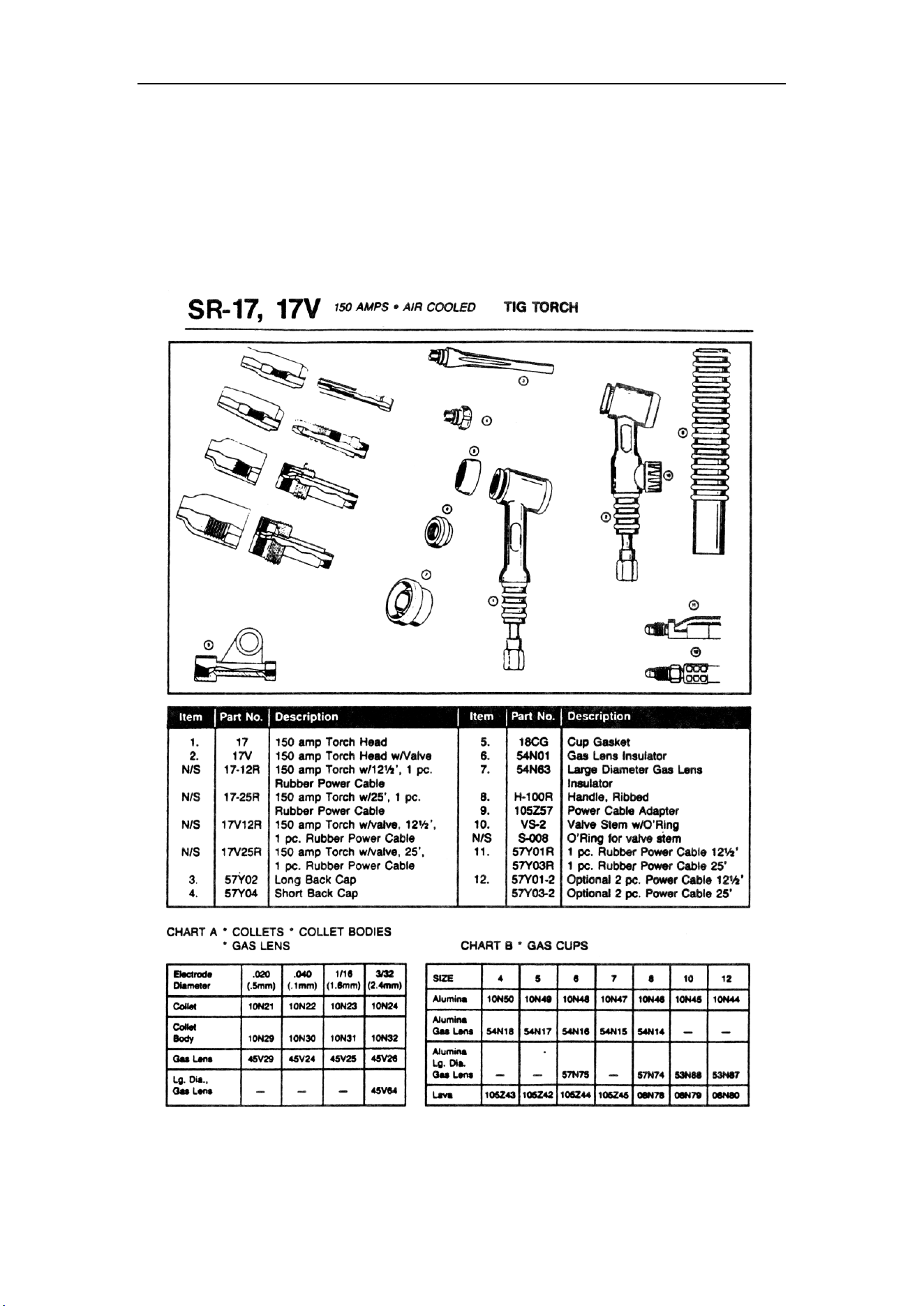
5.5 Exploded Torch Listing
TG2010 comes standard with a compact WP17 air-cooled TIG torch rated 60% duty-cycle
@ 150 amps (30% @ 200A) with 12.5’ direct-connect welding cable cover assembly with
Dinse power plug and 5/8-18RHM gas line fitting. For extended duty-cycle operation or for
higher power rated air-cooled or water-cooled torches, contact your Dealer.