Item #1008 624 851
Model #45071-050
USE AND CARE GUIDE
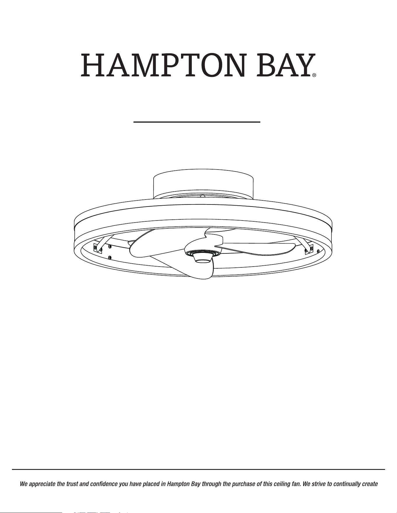
20-INCH INDOOR CEILING FAN
Questions, problems, missing parts? Before returning to the store,
call Hampton Bay Customer Service
8 a.m. - 7 p.m., EST, Monday-Friday,
9 a.m. - 6 p.m., EST, Saturday.
1-855-HD-HAMPTON
HAMPTONBAY.COM
THANK YOU
quality products designed to enhance your home. Visit us online to see our full line of products available for your home improvement needs.
Thank you for choosing Hampton Bay!
Item #1008 624 853
Model #45071-010
Item #1008 624 858
Model #45071-040
2
Table of Contents ................................................................ 2
Safety Information ............................................................... 2
Warranty ............................................................................... 3
Pre-Installation .................................................................... 3
Installation ............................................................................ 6
Operation ........................................................................... 9
Care and Cleaning .............................................................11
Troubleshooting ................................................................. 11
Safety Information
Table of Contents
READ AND SAVE THESE INSTRUCTIONS.
All wiring must be in accordance with the National Electrical
Code ANSI/NFPA 70 and local electrical codes. Electrical
installation should be performed by a qualified licensed
electrician.
To avoid personal injury or damage to the fan and other items,
use caution when working around or cleaning the fan.
All setscrews must be checked and retightened where
necessary before installation.
WARNING: To avoid possible electrical shock,
turn the electricity off at the main fuse box before
wiring. If you feel you do not have enough electrical
wiring knowledge or experience, contact a licensed
electrician.
Changes or modifications not expresslyCAUTION:
approved by the party responsible for compliance could
void the user’s authority to operate the equipment.
WARNING: To reduce the risk of personal injury, do not
WARNING:
bend the blade brackets when installing the brackets,
balancing the blades, or cleaning the fan. Do not insert
foreign objects in between rotating fan blades.
To reduce the risk of fire, electric shock
or personal injury, mount to an outlet box marked
“acceptable for fan support of 15.9 kg (35 lbs) or less”
and use screws provided with the outlet box.
WARNING:
shock, do not use this fan with any solid-state speed
control device.
To reduce the risk of fire or electric
CAUTION: To reduce the risk of personal injury,
use only the screws provided with the outlet box.
FCC Statement
...................................................................12
The fan must be mounted with a minimumCAUTION:
of 7 ft. (2.1 m) of clearance from the trailing edge of the
blades to the floor.
□
□
□
3
Pre-Installation
Warranty
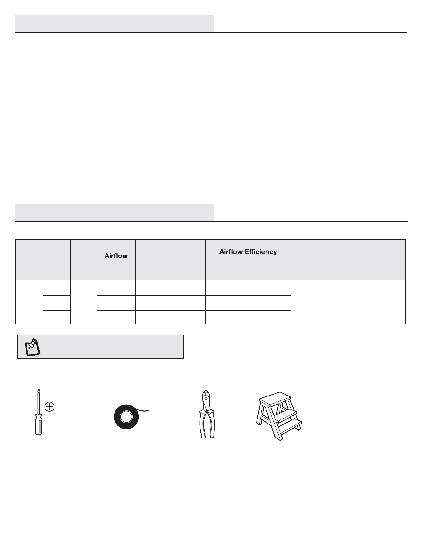
TOOLS REQUIRED
NOTE: These are approximate measures. They do not
include the amps and wattage used by the light kit.
Phillips
screwdriver
Electrical
tape
Wire
cutter
Step ladder
Contact the Customer Service Team at 1-855-HD-HAMPTON or visit www.HamptonBay.com.
We warrant the fan motor to be free from defects in workmanship and material present at time of shipment from the factory for a period of a lifetime
after the date of purchase by the original purchaser. We warrant that the light kit to be free from defects in workmanship and material at the time of
shipment from the factory for a period of three years after the date of purchase by the original purchaser. We also warrant that all other fan parts,
excluding any glass or acrylic blades, to be free from defects in workmanship and material at the time of shipment from the factory for a period of
two years after the date of purchase by the original purchaser. We agree to correct such defects without charge or at our option replace with a
comparable or superior model if the product is returned. To obtain warranty service, you must present a copy of the receipt as proof of purchase. All
costs of removing and reinstalling the product are your responsibility. Damage to any part such as by accident, misuse, improper installation, or by
affixing any accessories, are not covered by this warranty. Because of varying climatic conditions, this warranty does not cover any changes in brass
finish, including rusting, pitting, corroding, tarnishing or peeling. Brass finishes of this type give their longest useful life when protected from varying
weather conditions. A certain amount of “wobble” is normal and should not be considered a defect. Servicing performed by unauthorized persons
shall render the warranty invalid. There is no other express warranty. We hereby disclaim any and all warranties, including but not limited to those
of merchantability and fitness for a particular purpose to the extent permitted by law. The duration of any implied warranty which cannot be
disclaimed is limited to the time period as specified in the express warranty. Some states do not allow limitation on how long an implied warranty
lasts, so the above limitation may not apply to you. The retailer shall not be liable for incidental, consequential, or special damages arising out of or in
connection with product use or performance except as may otherwise be accorded by law. Some states do not allow the exclusion of incidental or
consequential damages, so the above exclusion or limitation may not apply to you. This warranty gives specific legal rights, and you may also have
other rights which vary from state to state. This warranty supersedes all prior warranties. Shipping costs for any return of the product as part
of a claim on the warranty must be paid by the customer.
SPECIFICATIONS
136.43
88.87
78.19
689
911
1011
Size Speed Volts
CFM
Fan Power
Consumption
(Without Lights)
WATT
(Higher Is Better)
CFM/WATT
Net
Weight
Gross
Weight
Cubic Feet
20 in.
Low
120
12.93
1.98 cu. ft.
Medium 10.25
High
5.05
5.73 lbs
(2.6 kgs)
9.47 lbs
(4.3kgs)
HAMPTONBAY.COM
Please contact 1-855-HD-HAMPTON for further assistance.
4
Pre-Installation (continued)
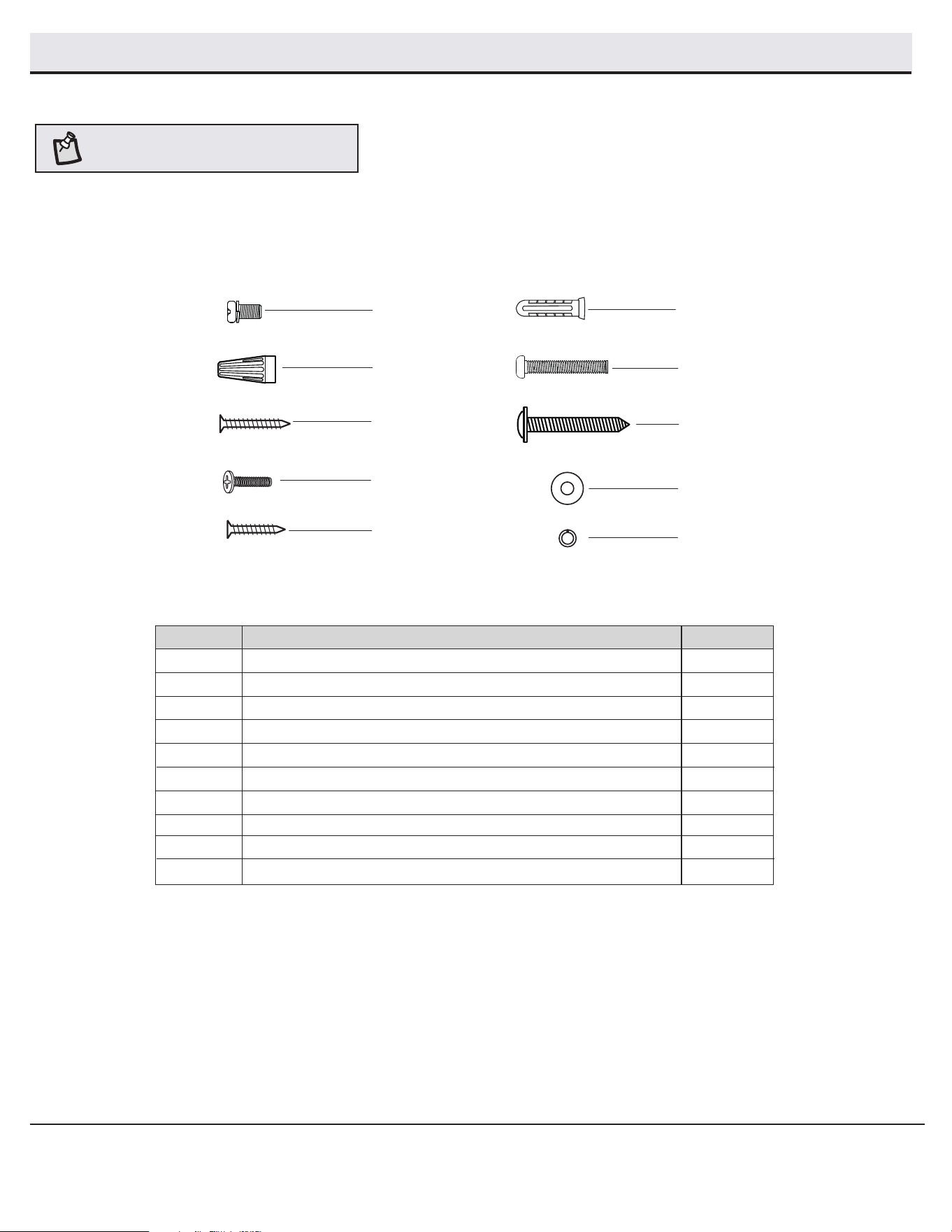
HARDWARE INCLUDED
NOTE: Hardware not shown to actual size.
AA
BB
CC
FF
DD
HH
GG
JJ
II
AA
BB
CC
DD
EE
Wire nut
Mounting screw 4
Remote control holder screw (Machine screws #6/32 )
4
2
2
2
2
Plastic anchor
Remote control holder screw (Wood screws ST3.0 )
4
FF
II
Wood screw
Part
Description
Quantity
Machine screw
HH
Metal washer
GG
6
2
Spring washer
EE
Remote control holder screw (Wood screws ST3.0 ) 2
JJ
5
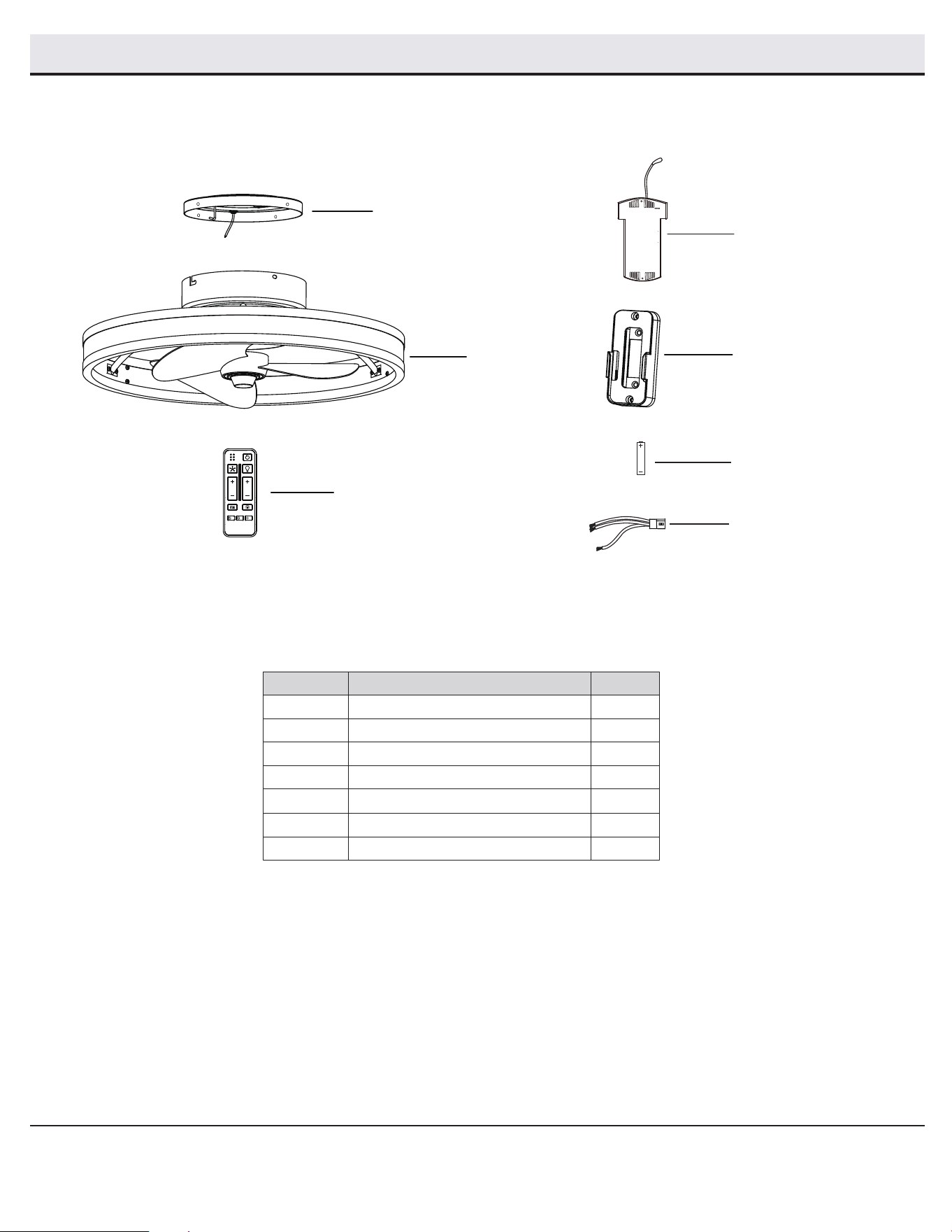
PACKAGE CONTENTS
D
E
Receiver
Remote control holder
1
1
A
B
C
1
1
1
Mounting plate
Fan motor assembly
Remote control
B
C
A
Part
Description
Quantity
Pre-Installation (continued)
D
F
HAMPTONBAY.COM
Please contact 1-855-HD-HAMPTON for further assistance.
E
F Battery AAA 1.5 V
2
BREEZE COLOR TEMP.
ON / OFF ON / OFF
6 SPEED BRIGHTNESS
TIMER
ALL
HR
2
HR
4
HR
8
G
G Lead wire with connector
1
6
Installation
MOUNTING OPTIONS
WARNING:
personal injury, mount to outlet box marked “acceptable
for fan support of 15.9 Kg (35 lbs) or less” using the
screws provided with the outlet box. An outlet box
not be acceptable for fan support and may need to be
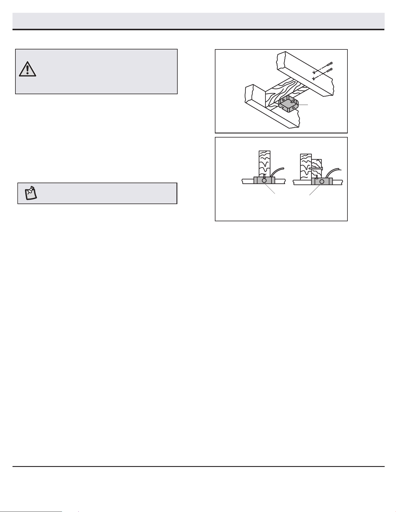
If your ceiling fan does not have an existing UL-listed mounting
box, then install one using the following instructions:
□
Disconnect the power by removing the fuses or turning off
the circuit breakers.
□ Secure the outlet box directly to the building structure.
Use the appropriate fasteners and materials. The outlet box
and its bracing must be able to fully support the weight
of the moving fan (at least 15.9 kg). Do not use a plastic
outlet box.
Outlet Box
Outlet Box
To reduce the risk of fire, electric shock, or
commonly used for the support of lighting fixtures may
replaced. If in doubt, consult a qualified electrician.
Option 1
Option 2
NOTE: The illustrations on the right show two
different ways to mount the outlet box.
7
HAMPTONBAY.COM
Please contact 1-855-HD-HAMPTON for further assistance.
Hanging the fan-motor assembly
Making the electrical connections
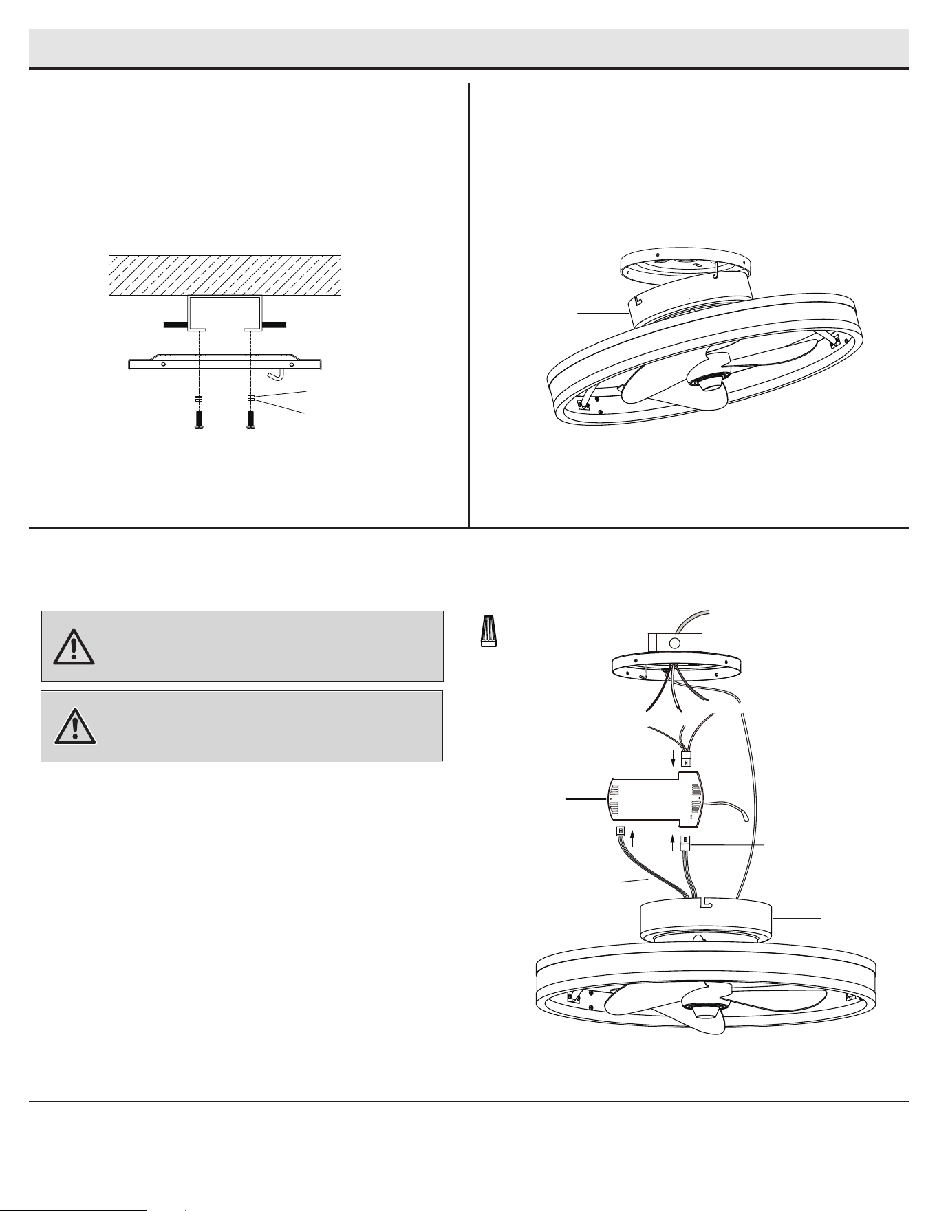
Attaching the mounting plate to
the electrical box
□ Secure the mounting plate (A) to the ceiling outlet box by using
the metal washers (II), spring washers (JJ) and the screws
provided with your outlet box.
□ Carefully lift the fan-motor assembly (B) and engage the slot
in the motor bracket on the top of the fan motor assembly (B)
with the hook on the mounting plate (A) so that it is securely
suspended.
2
3
1
Installation - Hanging the Fan
WARNING:
the electricity is turned off at the circuit breaker or main
fuse box before wiring.
To avoid possible electrical shock, ensure
WARNING:
including the ground, and that no bare wire is visible at
the wire nuts, except for the ground wire.
Check to see that all connections are tight,
BB (x4)
A
Outlet box
in the ceiling
Green
White
Black
Green
□ Spread the wires apart so that the green and white wires
are on one side of the outlet box and the black wire is on the
other side.
□ Connect the green wire from receiver (D) to the household ground
wire using a wire nut (BB).
□ Connect the receiver (D) black wire to the household black
(hot) wire using a wire nut (BB).
□ Connect the receiver (D) white wire to the household white
(neutral) wire using a wire nut (BB).
□ Secure each wire nut (BB) using electrical tape.
B
□ Connect the green fan wires to the mounting plate ground wire
using a wire nut (BB).
□ Connect the wires from the fan motor assembly (B) to the receiver (D)
by the wire connectors, push them together.
A
B
Motor wires
(red/gray/pink)
Light kit wires
(yellow/white/red)
G
D
□
Connect the lead wires (G) to receiver (D) by the wire connectors.
II
JJ
8
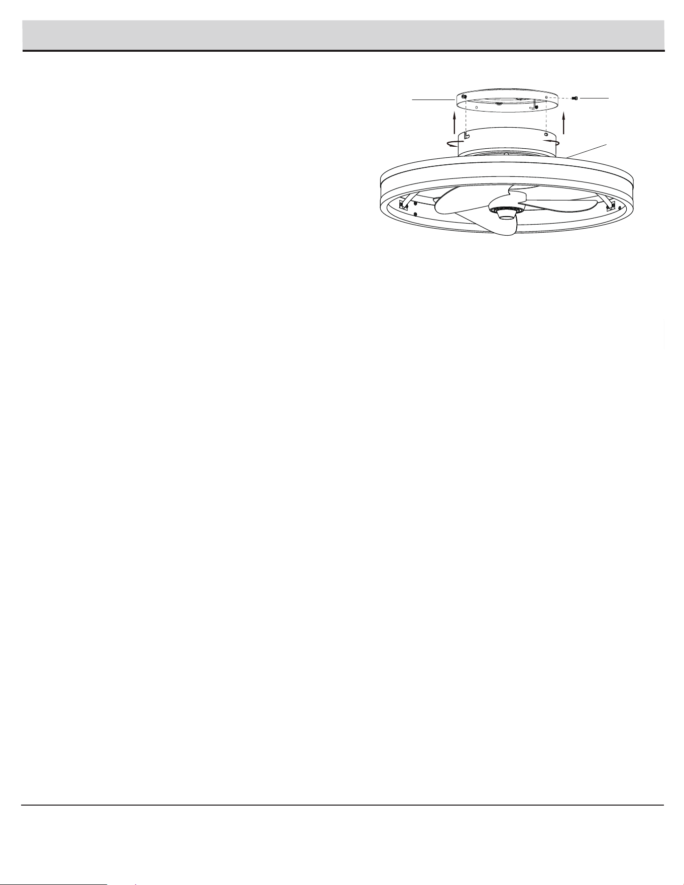
Installation - Hanging the Fan (continued)
B
Completing the fan assembly
4
□
Install the two mounting screws (AA) on two diagonal sides
of the top of the mounting plate (A).
Push the fan motor assembly (B) up and turn it counterclockwise
to lock in the mounting plate (A). Install the mounting screws (AA)
into the remaining two holes. Tighten the four mounting screws
(AA) firmly.
□
AA
A
9
Operation
HAMPTONBAY.COM
Please contact 1-855-HD-HAMPTON for further assistance.
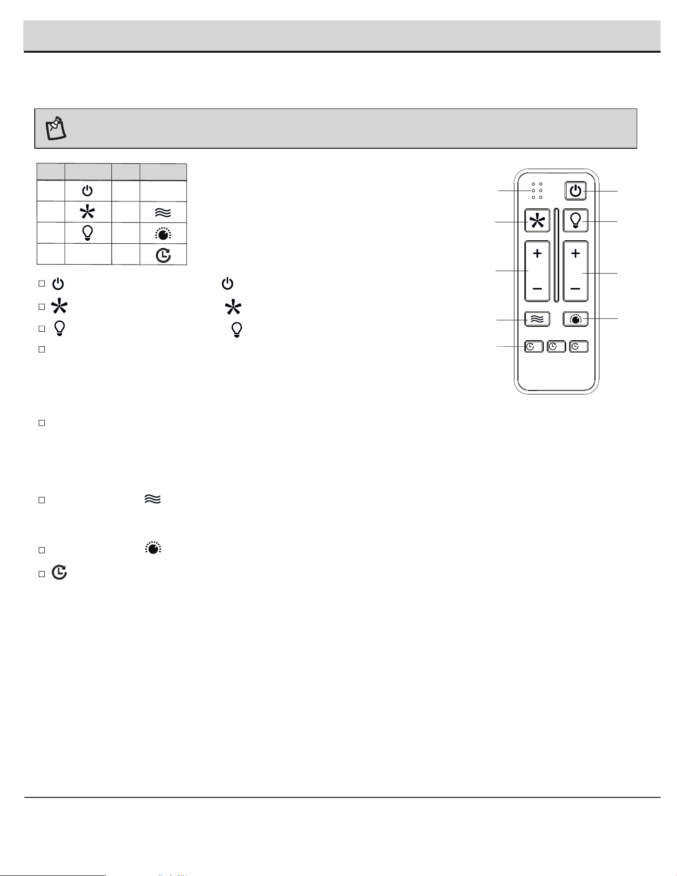
NOTE:
On start up, your ceiling fan will oscillate back and forth. This is NORMAL OPERATION for a DC ceiling fan as it goes through its
calibration cycle. The fan is NOT DEFECTIVE.
Light ON/ OFF: Press and release the button (C), the light will turn ON and OFF accordingly.
Speed functions:
Fan ON/ OFF: Press and release the button (B), the fan will turn ON and OFF accordingly.
Press and release the button (F) will activate the Comfort Breeze mode.
- Alternates through speeds 1-5.
- Press and hold the button (F) for 3 seconds to cancel the comfort Breeze mode.
All ON/ OFF: Press and release the button (A) to turn the fan and light ON or OFF.
Press and release the button (G) to change the light colour from warm light to white light.
Button (D): Increases the fan speed
Press and release the button (D) one time will increase the speed of the fan.
-
-
-
+
+
-+
+
Button (D): Decreases fan speed
Press and release the button (D) one time will decrease the speed of the fan.
Timer function
Dimmer functions:
Button (E): Increases the brightness of the light
Press and release the button (E) one time will increase the brightness of the light.
-
-
+
+
Button (E): Decreases the brightness of the light
Press and release the button (E) one time will decrease the brightness of the light.
- The timer function is only available for fan, not for the light kit.
- The timer function can only be activated when the fan is ON.
- Press the (2H/4H/8H) button (H) to set the timer.
- Hold and press the (2H/4H/8H) button (H) for 3 seconds to cancel the timer.
- When the timer is activate, press the (2H/4H/8H) button (H) again will reset the timer.
A
B
C
D
E
F
G
H
Part Symbol
Part Symbol
B
D
F
H
BREEZE COLOR TEMP.
ON / OFF ON / OFF
6 SPEED BRIGHTNESS
TIMER
ALL
HR
2
HR
4
HR
8
LED light
A
C
E
G
5
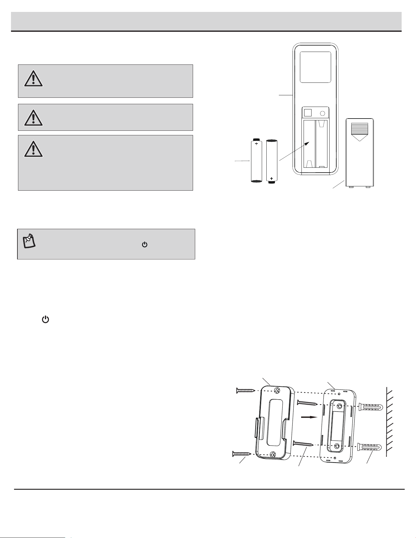
Operating the Remote Control
10
Operation (continued)
□
Install the plastic anchors (FF) onto the wall, install the remote control
holder spacer onto the wall using two longer remote control holder
screws (CC). Attach the remote control holder (E) onto the spacer,
ensure two parts fit together and no gaps, install the two shorter
remote control holder screws (EE) to the wall and secure tightly.
Turn the main power source off to begin the learning process.
Return the power to the unit.
Within 3 seconds of turning the fan’s AC power ON, and then press
the button for 5 seconds to enter the learning function. A beeping
sound is emitted when pairing is complete.
Should you desire to use another remote control (C) unit with your
new fan, install one using the steps below:
NOTE: After the AC power is on, do not press any other button
on the remote control before pressing the (ON/OFF) button.
Doing so will cause the procedure to fail.
□
□
□
Install two 1.5V (F) batteries into the remote control (C). To prevent damage to
the remote control, remove the battery if not used for long periods of time.
E
spacer
CC
F
C
Back cover
+
+
EE
FF
□
WARNING: Do not short-circuit, disassemble, heat up,
connect improperly, or dispose of used batteries in fire. Do
not recharge or mix batteries with used or other battery
types. Immediately remove used batteries.
WARNING: The batteries shall be disposed of properly,
including keeping them away from children; and even used
may cause injury.
WARNING: Chemical Burn Hazard. Keep batteries away
from children. Always completely secure the battery
compartment. If the battery compartment does not close
securely, stop using the product, remove the batteries, and
keep it away from children. If you think batteries might have
been swallowed or placed inside any part of the body, seek
immediate medical attention.
6
Learning Process
7
Installing the Remote Control Holder
11
Troubleshooting
HAMPTONBAY.COM
Please contact 1-855-HD-HAMPTON for further assistance.
Problem Solution
The fan will not
start.
□ Check the main and branch circuit fuses or breakers.
□
□
Check the line wire connections to the fan.
□
Check the battery in the remote control.
□
Ensure you are in the normal range of 10-20 feet.
Ensure the remote control and receiver are paired.
The fan is noisy.
□ Ensure all motor housing screws are snug.
This fan has a one-piece blade design, fan blade balancing kit is not applicable to this product.
If the fan wobbles, disconnect the power by removing the fuses or turning off the circuit breakers from the main
power source, then check the fan blade nut, make sure the nut is tighted.
If the problem persists, please contact our customer service.
□
□
Ensure the wire nut connections are not rattling against each other.
□
Allow a 24-hour “breaking in” period. Most noises associated with a new fan disappear during this time.
□
Ensure the canopy is a short distance from the ceiling. It should not touch the ceiling.
Ensure your outlet box is secure and rubber isolator pads were used between the mounting plate and outlet box.
The fan is wobbles. □
□
□
This is normal start-up procedure for DC motor fans. The partial movement during start-up is the result of the DC
motor aligning the internal magnetic poles for proper motor operation. This design saves electricity and allows
the fan to operate much quieter than standard AC motor fans.
Fan moves
backwards and
forwards when
turned on.
□
□ Because of the fan’s natural movement, some connections may become loose. Check the support connections, brackets, and blade
attachments twice a year. Make sure they are secure. It is not necessary to remove the fan from the ceiling.
□ Clean your fan periodically to help maintain its new appearance. Do not use water when cleaning, as this could damage the motor,
with a lacquer to minimize discoloration or tarnishing.
□ You do not need to oil your fan. The motor has permanently lubricated, sealed ball bearings.
WARNING: Make sure the power is off before cleaning
your fan.
or possibly cause an electrical shock. Use only a soft brush or lint-free cloth to avoid scratching the finish. The plating is sealed
□
Always unplug the fan before cleaning, disassembly or servicing.
Care and Cleaning

Questions, problems, missing parts? Before returning to the store,
call Hampton Bay Customer Service
8 a.m. - 7 p.m., EST, Monday-Friday,
9 a.m. - 6 p.m., EST, Saturday.
1-855-HD-HAMPTON
HAMPTONBAY.COM
Retain this manual for future use.
FCC Statement
This equipment has been tested and found to comply with the limits for a Class B digital device, pursuant to Part 15 of the FCC Rules. These limits are
designed to provide reasonable protection against harmful interference in a residential installation. This equipment generates uses and can radiate
radio frequency energy and, if not installed and used in accordance with the instructions, may cause harmful interference to radio communications.
However, there is no guarantee that interference will not occur in a particular installation. If this equipment does cause harmful interference to radio
or television reception, which can be determined by turning the equipment off and on, the user is encouraged to try to correct the interference by one
or more of the following measures:
Reorient or relocate the receiving antenna.
Increase the separation between the equipment and receiver.
Connect the equipment into an outlet on a circuit different from that to which the receiver is connected.
Consult the dealer or an experienced radio/TV technician for help.
CAUTION:
This device complies with Part 15 of the FCC Rules. Operation is subject to the following two conditions:
(1) This device may not cause harmful interference, and
(2) this device must accept any interference received, including interference that may cause undesired operation.
Any changes or modifications not expressly approved by the grantee of this device could void the user’s authority to operate the equipment.
The following responsible party designated in FCC §2.909 is responsible for this declaration:
Model Number: 45071-050, 45071-010, 45071-040,
Company Name: Eurofase Inc.
Company Address: 60 Industrial Parkway, Unit 802, Cheektowaga, NY 14227-2713
Full Name: Justin Lei Title: Product Manager
Telephone Number: 905-695-2055 Ext. 2238 Fax: 905-695-2056
□
□
□
□