BULLETIN NO.
54-07-3545
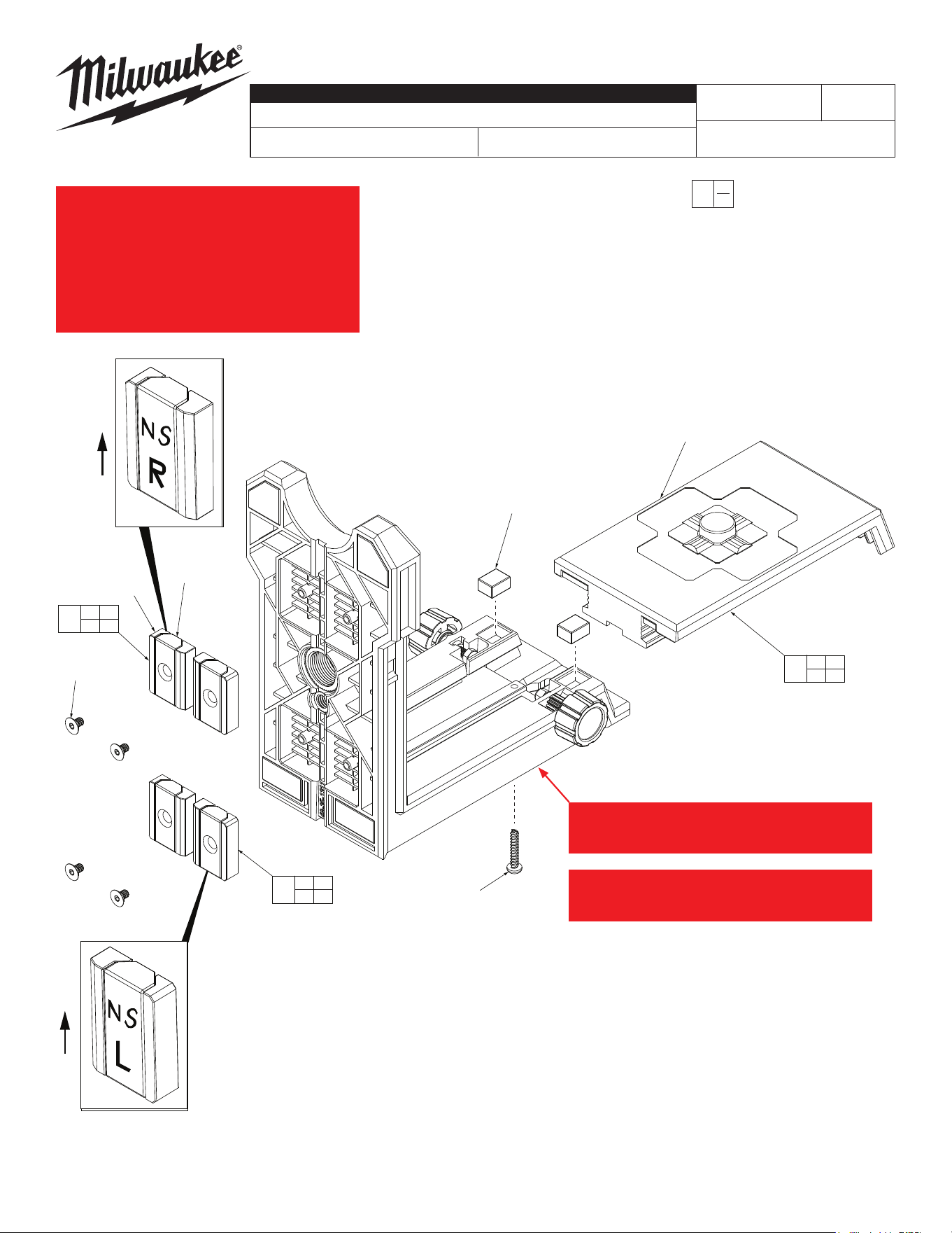
SERVICE PARTS LIST
FIG. PART NO. DESCRIPTION OF PART NO. REQ.
1 -------------- Steel Strap (16)
2 -------------- Magnet (8)
3 -------------- M3 x 7mm T10 FH Screw (8)
4 -------------- Friction Magnet (2)
5 44-26-0140 Right Magnet Assembly (4)
6 -------------- M3 x 16mm T10 PH ST Screw (1)
7 -------------- Back Plate (1)
8 31-10-0045 Back Plate Kit (1)
9 44-26-0135 Left Magnet Assembly (4)
CATALOG NO. 48-35-1311
REVISED BULLETIN
SPECIFY CATALOG NO. AND SERIAL NO. WHEN ORDERING PARTS
360 Laser Mount
STARTING
SERIAL NO.
DATE
Aug. 2020
WIRING INSTRUCTION
0
00
EXAMPLE:
Component Parts (Small #)
Are Included When Ordering
The Assembly (Large #).
6
1
(x16)
7
3
(x8)
4
(x2)
2
(x8)
8
4 6
7
5
1 2
3
9
1 2
3
MILWAUKEE TOOL
l
www.milwaukeetool.com
13135 W. Lisbon Road, Brookeld, Wisc. 53005
Drwg. 1
Inspect sticker applied to the face of the Magnet (2). Inspect sticker applied to the face of the Magnet (2).
Orient the Magnet and Steel Strap (1) so that the Orient the Magnet and Steel Strap (1) so that the
"N/S" faces in the upward direction relative to the "N/S" faces in the upward direction relative to the
tool. The left (L) is inserted into the left side of the tool. The left (L) is inserted into the left side of the
bracket and the right (R) magnet is inserted into the bracket and the right (R) magnet is inserted into the
right side. Insert the Magnet and Steel Strap into the right side. Insert the Magnet and Steel Strap into the
mount so that the post aligns with the inner diameter mount so that the post aligns with the inner diameter
on the magnet. After the Magnet and Steel Strap is on the magnet. After the Magnet and Steel Strap is
inserted into the mount, the sticker can be removed inserted into the mount, the sticker can be removed
and the screws (4) can be hand tightened. Do not and the screws (4) can be hand tightened. Do not
over tighten.over tighten.
2 additional sets of Left (L) Magnet Assemblies (5) 2 additional sets of Left (L) Magnet Assemblies (5)
and Right (R) Magnet assemblies (9) are located and Right (R) Magnet assemblies (9) are located
here.here.
In order to remove the Back Plate (7), remove Screw In order to remove the Back Plate (7), remove Screw
(6). The screw will act like a stop so the back plate (6). The screw will act like a stop so the back plate
does not come o with misuse.does not come o with misuse.
*
*