
micro CA-350
Inspection Camera
• Français – 17
• Castellano – pág. 35
• Türkçe – 53
• Русский язык – 69
micro CA-350 Operator’s Manual

ii
micro CA-350 Inspection Camera
Table of Contents
Safety Symbols.....................................................................................................................2
General Safety Information
Work Area Safety...............................................................................................................2
Electrical Safety.................................................................................................................2
Personal Safety .................................................................................................................2
Equipment Use and Care ..................................................................................................2
Battery Use and Care ........................................................................................................2
Service ..............................................................................................................................3
Specific Safety Information
micro CA-350 Inspection Camera Safety...........................................................................3
Description, Specifications and Standard Equipment
Description ........................................................................................................................4
Specifications ....................................................................................................................4
Standard Equipment..........................................................................................................5
Controls .............................................................................................................................5
FCC Statement......................................................................................................................5
Electromagnetic Compatibility (EMC) ................................................................................6
Icons......................................................................................................................................6
Tool Assembly
Changing/Installing Batteries.............................................................................................7
Powering with the AC Adapter ...........................................................................................7
Installing Imager Head Cable or Extension Cables ...........................................................7
Installing Accessories ........................................................................................................7
Installing SD™ Card ..........................................................................................................8
Pre-Operation Inspection ....................................................................................................8
Tool and Work Area Set-Up..................................................................................................8
Operating Instructions.........................................................................................................9
Live Screen......................................................................................................................10
Image Adjustment............................................................................................................10
Image Capture .................................................................................................................11
Menu................................................................................................................................11
Time Stamp .....................................................................................................................12
Language.........................................................................................................................12
Date/Time ........................................................................................................................12
TV-Out .............................................................................................................................12
Update Firmware .............................................................................................................12
Speaker ...........................................................................................................................12
Auto Power Off.................................................................................................................12
Factory Reset ..................................................................................................................12
About ...............................................................................................................................12
Transferring Images to a Computer .................................................................................12
Connecting to TV .............................................................................................................13
Using with SeeSnake
®
Inspection Equipment ........................................................................13
Maintenance
Reset Function.................................................................................................................14
Optional Equipment ...........................................................................................................14
Storage ................................................................................................................................14
Service and Repair .............................................................................................................14
Disposal ..............................................................................................................................15
Troubleshooting .................................................................................................................16
Lifetime Warranty .................................................................................................Back Cover
*Original Instructions - English

micro CA-350
Inspection Camera
microCA-350
micro CA-350 Inspection Camera
Record Serial Number below and retain product serial number which is located on nameplate.
Serial
No.
WARNING!
Read this Operator’s Man ual
carefully before using this
tool. Failure to understand
and follow the contents of this
manual may result in electri-
cal shock, fire and/or serious
person al injury.
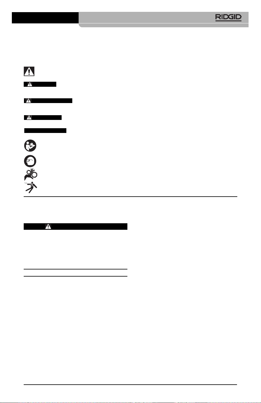
Safety Symbols
In this operator’s manual and on the product, safety symbols and signal words are used to
communicate important safety information. This section is provided to improve under-
standing of these signal words and symbols.
This is the safety alert symbol. It is used to alert you to potential personal injury hazards.
Obey all safety messages that follow this symbol to avoid possible injury or death.
DANGER indicates a hazardous situation which, if not avoided, will result in death or
serious injury.
WARNING indicates a hazardous situation which, if not avoided, could result in
death or serious injury.
CAUTION indicates a hazardous situation which, if not avoided, could result in minor
or moderate injury.
NOTICE indicates information that relates to the protection of property.
This symbol means read the operator’s manual carefully before using the equipment. The op-
erator’s manual contains important information on the safe and proper operation of the equip-
ment.
This symbol means always wear safety glasses with side shields or goggles when handling
or using this equipment to reduce the risk of eye injury.
This symbol indicates the risk of hands, fingers or other body parts being caught or wrapped
in gears or other moving parts.
This symbol indicates the risk of electrical shock.
• Do not expose equipment to rain or wet
conditions. Water en tering equipment will
increase the risk of electrical shock.
Personal Safety
• Stay alert, watch what you are doing
and use common sense when operat-
ing equipment. Do not use equipment
while you are tired or under the influ-
ence of drugs, alcohol or medication. A
moment of inattention while operating
equipment may result in serious personal
injury.
• Do not overreach. Keep proper footing
and balance at all times. This enables
better control of the power tool in unex-
pected situations.
• Use personal protective equipment.
Always wear eye protection. Protective
equipment such as dust mask, non-skid
safety shoes, hard hat or hearing protection
used for appropriate conditions will reduce
personal injuries.
Equipment Use and Care
• Do not force equipment. Use the correct
equipment for your application. The cor-
rect equipment will do the job better and
safer at the rate for which it is designed.
2
micro CA-350 Inspection Camera
General Safety
Information
WARNING
Read all safety warnings and instruc-
tions. Failure to follow the warnings and
instructions may result in electric shock,
fire and/or serious injury.
SAVE THESE INSTRUCTIONS!
Work Area Safety
• Keep your work area clean and well lit.
Cluttered or dark areas invite accidents.
• Do not operate equipment in explosive
atmospheres, such as in the presence of
flammable liquids, gases or dust. E quip -
ment can create sparks which may ignite
the dust or fumes.
• Keep children and by-standers a way
while operating equipment. Distrac tions
can cause you to lose control.
Electrical Safety
• Avoid body contact with earthed or
ground ed surfaces such as pipes, radi-
ators, ranges and refrigerators. There
is an increased risk of electrical shock if
your body is earthed or grounded.
NOTICE
DANGER
WARNING
CAUTION

other. Shorting the battery terminals to-
gether may cause burns or a fire.
• Under abusive conditions, liquid may
be ejected from the battery; avoid con-
tact. If contact accidentally occurs, flush
with water. If liquid contacts eyes, addition-
ally seek medical help. Liquid ejected from
the battery may cause irritation or burns.
Service
• Have your equipment serviced by a
qual i fied repair person using on ly iden-
tical replacement parts. This will ensure
that the safety of the tool is maintained.
Specific Safety
Information
WARNING
This section contains important safety in-
formation that is specific to the inspec-
tion camera.
Read these precautions carefully before
using the RIDGID
®
micro CA-350 In spec -
tion Cam era to reduce the risk of electri-
cal shock or other serious injury.
SAVE THESE INSTRUCTIONS!
A manual holder is supplied in the carrying
case of the micro CA-350 Inspection Camera
to keep this manual with the tool for use by
the operator.
micro CA-350 Inspection
Camera Safety
• Do not expose the display unit to water
or rain. This increases the risk of electri-
cal shock. The micro CA-350 imager head
and ca ble are waterproof to 10' (3 m). The
hand-held display unit is not.
• Do not place the micro CA-350 Inspec -
tion Cam era anywhere that may con-
tain a live electrical charge. This in-
creases the risk of electrical shock.
• Do not place the micro CA-350 Inspec -
tion Cam era anywhere that may con-
tain moving parts. This increases the risk
of entanglement injuries.
• Do not use this device for personal in-
spection or medical use in any way.
This is not a medical device. This could
cause personal injury.
• Do not use equipment if the switch does
not turn it ON and OFF. Any tool that can-
not be controlled with the switch is dan-
gerous and must be repaired.
• Disconnect the batteries from the e quip -
ment before making any adjustments,
changing accessories, or storing. Such
preventive safety measures reduce the risk
of injury.
• Store idle equipment out of the reach of
children and do not allow persons unfa-
miliar with the equipment or these in-
structions to operate the equipment.
Equipment can be dangerous in the hands
of untrained users.
• Maintain equipment. Check for missing
parts, breakage of parts and any other
condition that may affect the equipment’s
operation. If damaged, have the equip-
ment repaired before use. Many accidents
are caused by poorly maintained equip-
ment.
• Use the equipment and accessories in
accordance with these instructions,
taking into account the working condi-
tions and the work to be performed.
Use of the equipment for operations differ-
ent from those intended could result in a
hazardous situation.
• Use only accessories that are recom-
mended by the manufacturer for your
equipment. Accessories that may be suit-
able for one piece of equipment may be-
come hazardous when used with other
equipment.
• Keep handles dry and clean; free from
oil and grease. Allows for better control of
the equipment.
Battery Use & Care
• Recharge only with the charger speci-
fied by the manufacturer. A charger that is
suitable for one type of battery pack may
create a risk of fire when used with an-
other battery pack.
• Use equipment only with specifically
designated battery packs. Use of any
other battery packs may create a risk of
injury and fire.
• When a battery pack is not in use, keep
it away from other metal objects, like
paper clips, coins, keys, nails, screws or
other small metal objects that can make
a connection from one terminal to an-
3
micro CA-350 Inspection Camera

Description,
Specifications and
Standard Equipment
Description
The RIDGID
®
micro CA-350 Inspection Cam -
era is a powerful handheld digital recording de-
vice. It is a complete digital platform that allows
you to perform inspections and record pic-
tures and videos in hard to reach areas. Sev -
eral image manipulation features such as
image rotation and digital zoom are built into
the system to ensure detailed and accurate vi-
sual inspections. The tool has external memory
and TV-Out features. Accessories (hook, mag-
net and mirror) are included to attach to the im-
ager head to provide application flexibility.
Specifications
Recommended Use.....Indoor
Viewable Distance.......0.4" (10 mm) to ∞
Display.........................3.5" (90 mm) Color
TFT (320 x 240
Resolution)
Camera Head ..............3/4" (17mm)
Lighting........................4 Adjustable LEDs
Cable Reach................3' (0,9 m), Expand -
able to 30' (9 m) with
Op tional Exten sions,
Imager and Cable
are Water proof to 10'
(3 m), IP67
Photo Format...............JPEG
Image Resolution ........640 x 480
Video Format...............MP4
Video Resolution .........640 x 480
Frame Rate..................up to 30 FPS
TV-Out .........................PAL/NTSC
User selectable
Built-In Memory ...........235 MB Memory
External Memory .........SD™ Card 32 GB
max (8 GB supplied)
Data Output .................USB Data Cable
and SD™ Card
Operating
Temperature ................32 to 113°F
(0 to 45°C)
Storage Temperature...-4°F to 140°F
(-20°C to 60°C)
• Always use appropriate personal pro-
tective equipment while handling and
using the micro CA-350 Inspection Cam -
er a. Drains and other areas may contain
chemicals, bacteria and other substances
that may be toxic, infectious, cause burns or
other issues. Appropriate personal pro-
tective equipment always includes safe -
ty glasses and gloves, and may include
equipment such as latex or rubber gloves,
face shields, goggles, protective clothing,
respirators and steel-toed foot wear.
• Practice good hygiene. Use hot, soapy
wa ter to wash hands and other body parts
exposed to drain contents after handling or
using the micro CA-350 In spec tion Camera
to inspect drains and other areas that may
contain chemicals or bacteria. Do not eat or
smoke while operating or handling the
micro CA-350 Inspection Camera. This will
help prevent contamination with toxic or
infectious material.
• Do not operate the micro CA-350 In -
spection Camera if operator or device is
standing in water. Operating an electrical
device while in water increases the risk of
electrical shock.
• Before operating a micro CA-350 In spec -
tion Camera, read and understand:
– This operator’s manual,
– The battery/charger manual,
– The instructions for any other equipment
used with this tool,
Failure to follow all instructions and warn-
ings may result in property damage and/or
serious injury.
The EC Declaration of conformity (890-011-
320.10) will accompany this manual as a sep-
arate booklet when required.
If you have any question concerning this
RIDGID
®
product:
– Contact your local RIDGID distributor.
– Visit RIDGID.com to find your local
RIDGID contact point.
– Contact Ridge Tool Technical Service
De part ment at rtctechservices@emer -
son.com, or in the U.S. and Canada call
(800) 519-3456.
4
micro CA-350 Inspection Camera

Figure 3 – Right Side Port Cover
Figure 4 – Left Side Port Cover
FCC Statement
This equipment has been tested and found to
comply with the limits for a Class B digital
device, pursuant to part 15 of the FCC Rules.
These limits are designed to provide reason-
able protection against harmful interference in
a residential installation.
This equipment generates, uses, and can ra-
diate radio frequency energy and, if not in-
stalled and used in accordance with the in-
structions, may cause harmful interference
to radio communications.
However, there is no guarantee that interfer-
ence will not occur in a particular installation.
If this equipment does cause harmful interfer-
ence to radio or television reception, which can
be determined by turning the equipment OFF
and ON, the user is encouraged to try to cor-
rect the interference by one or more of the fol-
lowing measures:
• Reorient or relocate the receiving antenna.
Power Supply................12V Li-Ion Battery
AC Adapter 12V,
3 Amp
Weight...........................5.5 lbs (2,5 kg)
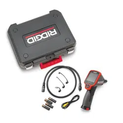
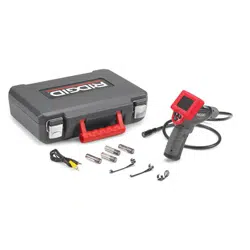
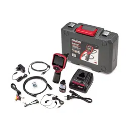
Standard Equipment
The micro CA-350 Inspection Camera comes
with the following items:
• micro CA-350 Handset
• 17 mm Imager
• 3' (90 cm) USB Cable
• 3' (90 cm) RCA Cable with Audio
• Hook, Magnet, Mirror Attachments
• 12 V Li-Ion Battery
• Li-Ion Battery Charger with Cord
• AC Adapter
• Headset Accessory with Microphone
• 8 GB SD™ Card
• Operator’s Manual Pack
Figure 1 – micro CA-350 Inspection Camera
Controls
Figure 2 – Controls
5
micro CA-350 Inspection Camera
Rotate
Image
Menu
Return
Power
Select/Confirm
Shutter
Arrows
Integrated
Microphone
AC Adapter
Headset
Jack
Speaker
TV-Out
Mini-B USB
SD™ Slot
Reset Button
Icons
Tool Assembly
WARNING
To reduce the risk of serious injury dur-
ing use, follow these procedures for
proper assembly.
• Increase the separation between the equip-
ment and receiver.
• Consult the dealer or an experienced radio/ -
TV technician for help.
Electromagnetic
Compatibility (EMC)
The term electromagnetic compatibility is
taken to mean the capability of the product to
function smoothly in an environment where
electromagnetic radiation and electrostatic
discharges are present and without causing
electromagnet interference to other equip-
ment.
The RIDGID micro CA-350 Inspect -
ion Camera conforms to all applicable EMC
standards. However, the possibility of it caus-
ing interference in other devices cannot be
precluded.
6
micro CA-350 Inspection Camera
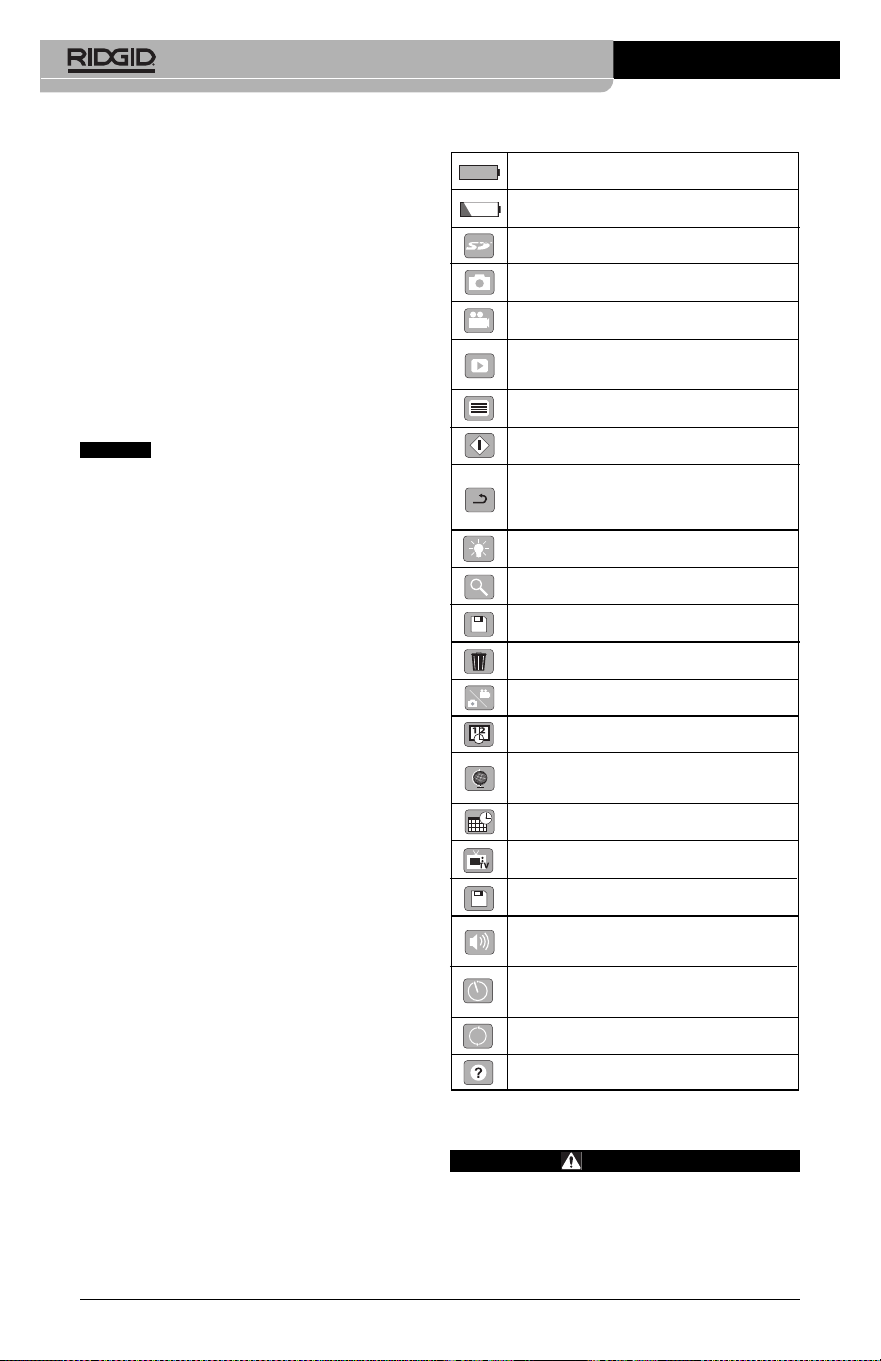
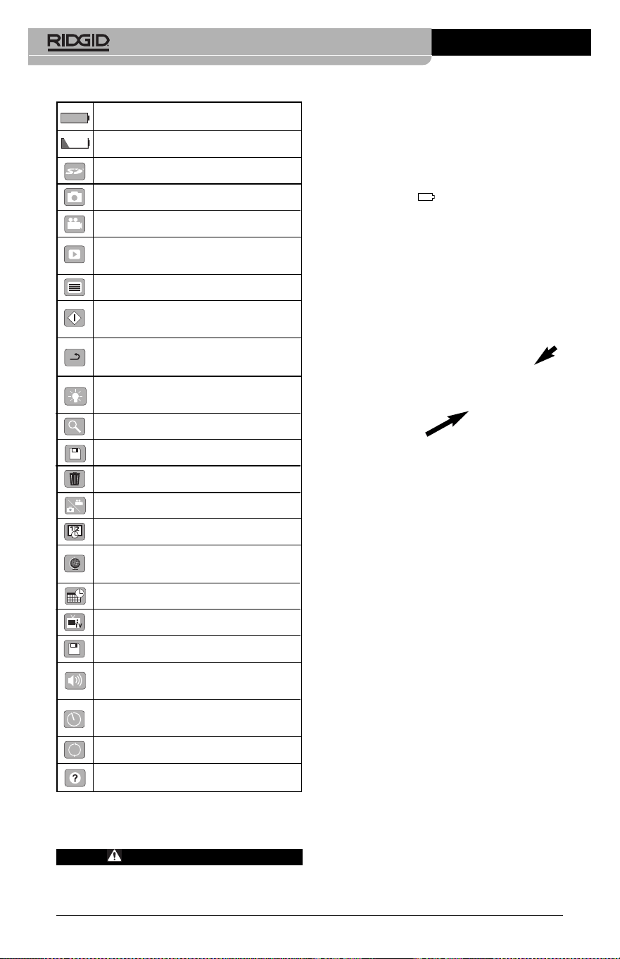
Battery Life Indicator – Fully charged
battery.
Battery Life Indicator – Less than 25%
of battery charge remains.
SD™ Card – Indicates an SD card has
been inserted into the device.
Still Camera – Indicates device is operat-
ing in still camera mode.
Video Camera – Indicates device is oper-
ating in video camera mode.
Playback Mode – Selecting this icon al-
lows you to view and delete previous ly
saved images and video.
Menu – Push select on this icon to be
taken to the menu screen.
Select – Pressing select from the live
screen will take you to the playback screen.
Return – Pressing return from the live
screen will switch between camera and
video. Return will also back out of menu
and playback mode.
LED Brightness – Press right & left ar-
rows to change the LED brightness.
Zoom – Press up & down arrows to
change the zoom from 1.0x to 2.0x.
Save – Indicates image or video has
been saved to memory.
Trash – Delete confirmation icon.
Mode – Select between image, video or
playback.
Time Stamp – Select to display or hide
date and time on live screen.
Language – Choose between, English,
French, Spanish, German, Dutch, Italian,
etc.
Time and Date – Enter this screen to set
time and date.
TV – Chose between NTSC and PAL to
enable TV out video format.
Update Firmware – Use to update unit
with most current software.
Speaker/Microphone – Turns speaker
and microphone ON or OFF during
recording and playback.
Automatic Power Off – Device will auto-
matically shut down after 5, 15 or 60 min-
utes of inactivity.
Factory Reset – Restore factory defaults.
About – Displays software version.
NOTICE

Figure 7 – Cable Connections
3' (90 cm) and 6' (180 cm) cable extensions are
available to increase the length of your camera
cable up to 30 feet (9 m). To install an extension,
first remove the camera head cable from the
display unit by loosening the knurled knob.
Connect the extension to the handheld as de-
scribed above (Figure 7). Connect the keyed
end of the camera head cable to the slotted end
of the extension and finger tighten the knurled
knob to hold the connection in place.
Installing Accessories
The three included accessories, (Hook, Mag -
net, Mirror) all attach to the imager head the
same way.
Figure 8 – Installing an Accessory
To connect, hold the imager head as shown in
Figure 8. Slip the semicircle end of the acces-
sory over the flats of the imager head. Then ro-
tate the accessory a 1/4 turn to retain.
Installing SD™ Card
Open the left side port cover (Figure 4) to ac-
cess the SD card slot. Insert the SD card into
the slot making sure the contacts are facing to-
wards you and the angled portion of the card is
facing down (Figure 9). SD cards can only be
installed one way – do not force. When an SD
card is installed, a small SD card icon will ap-
pear in the upper left hand portion of the
screen, along with the number of images or
length of video that can be stored on the SD
card.
Changing/Installing Batteries
The micro CA-350 is supplied without the bat-
tery installed. If the battery indicator displays
, the battery needs to be recharged. Re -
move the battery prior to storage.
1. Squeeze the battery tabs (See Figure 5)
and pull to remove battery.
Figure 5 – Removing/Installing Battery
2. Insert contact end of battery into the in-
spection tool, as shown in Figure 5.
Powering with the AC Adapter
The micro CA-350 Inspection Camera can al -
so be powered using the supplied AC Adapter.
1. Open the right side port cover (Figure 3).
2. With dry hands, plug the AC adapter into
the outlet.
3. Insert the AC adapter barrel plug into the
port marked “DC 12V”.
Figure 6 – Powering the Unit with AC Adapter
Installing the Imager Head
Cable or Extension Cables
To use the micro CA-350 Inspection Cam er a,
the imager head cable must be connected to
the handheld display unit. To connect the
cable to the handheld display unit, make sure
the camera socket key and display unit socket
slot (Figure 7) are properly aligned. Once they
are aligned, finger tighten the knurled knob to
hold the connection in place.
7
micro CA-350 Inspection Camera
Accessory
1/4 Turn
Flats
Figure 9 – Inserting the SD Card
Pre-Operation
Inspection
WARNING
Before each use, inspect your Inspec -
tion Camera and correct any problems
to reduce the risk of serious injury from
electric shock and other causes and
prevent tool damage.
1. Make sure the unit is OFF.
2. Remove the battery and inspect it for
signs of dam age. Re place battery if nec-
essary. Do not use Inspection Camera
if the battery is damaged.
3. Clean any oil, grease or dirt from the e -
quip ment. This aids inspection and helps
prevent the tool from slipping from your
grip.
4. Inspect micro CA-350 Inspection Camera
for any broken, worn, miss ing or binding
parts or any condition which may pre-
vent safe and normal operation.
5. Inspect the camera head lens for con-
densation. To avoid damaging the unit, do
not use the camera if condensation forms
inside the lens. Let the water evaporate
before using.
6. Inspect the full length of the cable for
cracks or damage. A damaged cable
could allow water to enter the unit and in-
crease the risk of electrical shock.
micro CA-350 Inspection Camera
8
7. Check to make sure the connections be-
tween the handheld unit, extension ca-
bles and imager cable are tight. All con-
nections must be properly assembled for
the cable to be water resistant. Con firm
unit is properly assembled.
8. Check that the warning label is present,
firmly attached and readable (Figure 10).
Figure 10 – Warning Label
9. If any issues are found during the in-
spection, do not use the inspection cam-
era until it has been properly serviced.
10. With dry hands, re-install the battery.
11. Press and hold the Power Button for one
second. The imager lights should come
on, then a splash screen will appear.
Once the camera is ready, a live image of
what the camera sees is displayed on
the screen. Con sult the Troubleshooting
section of this manual if no picture ap-
pears.
12. Press and hold the Power Button for one
second to turn camera OFF.
Tool and Work Area
Set-Up
WARNING
Set up the micro CA-350 In spec tion Cam -
era and work area according to these
procedures to reduce the risk of injury
from electrical shock, entanglement and
other causes and prevent tool damage.
1. Check work area for:
• Adequate lighting
• Flammable liquids, vapors or dust that
may ignite. If present, do not work in
area until sources have been identified
and corrected. The micro CA-350 In -
spection Camera is not explosion proof
and can cause sparks.
• Clear, level, stable, dry place for opera-
tor. Do not use the inspection camera
while standing in water.
2. Examine the area or space that you will
be inspecting and determine if the micro
CA-350 Inspection Camera is the correct
piece of equipment for the job.
• Determine the access points to the
space. The minimum opening the cam -
era head can fit through is approxi -
mate ly
3
/
4
" (19 mm) in diameter for the
17 mm camera head.
• Determine the distance to the area to
be inspected. Extensions can be add ed
to the camera to reach up to 30' (9 m).
• Determine if there are any obstacles
that would require very tight turns in
the cable. The inspection camera ca -
ble can go down to a 5" (127 mm) ra-
dius without damage.
• Determine if there is any electrical pow -
er supplied to the area to be inspected.
If so, the power to the area must be
turned OFF to reduce the risk of electric
shock. Use appropriate lock out pro-
cedures to prevent the power from
being turned back on during the in-
spection.
• Determine if any liquids will be encoun-
tered during the inspection. The cable
and imager head are waterproof to a
depth of 10' (3 m). Greater depths may
cause leakage into the cable and im-
ager and cause electric shock or dam-
age the equipment. The handheld dis-
play unit is water resistant (IP54) but
should not be submerged in water.
• Determine if any chemicals are pres-
ent, especially in the case of drains. It is
important to understand the specific
safety measures required to work a -
round any chemicals present. Contact
the chemical manufacturer for required
information. Chemicals may damage or
degrade the inspection camera.
• Determine the temperature of the area
and items in the area. See Specifi ca -
micro CA-350 Inspection Camera
9
tions. Use in areas outside of specifica-
tion temperatures or contact with hotter
or colder items could cause camera
damage.
• Determine if any moving parts are pres-
ent in the area to be inspected. If so,
these parts must be deactivated to pre-
vent movement during inspection to
reduce the risk of entanglement. Use
appropriate lock out procedures to pre-
vent the parts from moving during the
inspection.
If the micro CA-350 Inspection Camera is not
the correct piece of equipment for the job,
other inspection equipment is available from
RIDGID. For a complete listing of RIDGID
products, see the RIDGID catalog, online at
RIDGID.com.
3. Make sure the micro CA-350 Inspec tion
Camera has been properly inspect ed be-
fore each use.
4. Install the correct accessories for the ap-
plication.
Operating Instructions
WARNING
Always wear eye protection to protect
your eyes against dirt and other foreign
objects.
Follow operating instructions to reduce
the risk of injury from electrical shock,
entanglement and other causes.
1. Make sure that the Inspection Camera
and work area have been properly set
up and that the work area is free of
bystand ers and other distractions.
2. Press and hold the Power Button for two
seconds. The imager lights should come
ON, then a splash screen will appear.
This screen tells you the device is booting
up. Once the product is fully powered up,
the screen will automatically switch to
the live screen.

Figure 11 – Splash Screen
(Note: Version will change with each
firmware update.)
Live Screen
The live screen is where you will do most of
your work. A live image of what the camera
sees is displayed on the screen. You can zoom,
adjust LED brightness and take images or
video from this screen.
The screen has a status bar at the top showing
the tool mode, zoom, SD™ card icon if in-
serted, available memory and speaker/mic
ON/OFF. The bottom bar shows information
about date and time if time stamp is ON.
Figure 12 – Live Screen
When the Inspection Camera is turned ON, the
default mode is for capturing still images.
Pressing the menu button at any time will ac-
cess the menu. The menu will overlay on the
LIVE Screen. Use the right and left arrow
buttons to switch to the MODE category. Use
the up and down arrows to navigate be-
tween menu items and press select as de-
sired.
micro CA-350 Inspection Camera
10
Figure 13 – Screen Shot of Mode Selection
3. If the other inspection camera settings
(Time Stamp, Language, Date/Time, TV
Out, Update Firmware, Speaker/Micro -
phone, Auto Power OFF, Factory Reset)
need to be adjusted, see Menu Section.
4. Prepare the camera for inspection. The
camera cable may need to be pre-formed
or bent to properly inspect the area. Do not
try to form bends less than 5" (13cm) ra-
dius. This can damage cable. If inspecting
a dark space, turn the LEDs on before
inserting the camera or cable.
Do not use excessive force to insert or
withdraw the cable. This may result in
damage to the inspection camera or in-
spection area. Do not use the cable or im-
ager head to modify surroundings, clear
pathways or clogged areas, or as any-
thing other than an inspection device.
This may result in damage to the Inspec -
tion camera or inspection area.
Image Adjustment
Adjust LED Brightness : Pressing the right
and left arrow button on the button pad (In
live screen) will increase or decrease the
LED brightness. A brightness indicator bar
will be displayed on the screen as you adjust
brightness.
Status
Bar
Information
Bar

micro CA-350 Inspection Camera
11
Figure 14 – Adjusting LED
Zoom : The micro CA-350 Inspection Camer a
has a 2.0x digital zoom. Simply press the up
and down arrows while in the live screen
to zoom in or out. A zoom indicator bar will be
displayed on the screen as you adjust your
zoom.
Figure 15 – Adjusting Zoom
Image Rotation : If needed, the image/video
seen on the screen can be rotated in 90 de-
gree increments counter clockwise by press-
ing the rotate image button .
Image Capture
Capturing a Still Image
While in the live screen, make sure the still
camera icon is present at the top left por-
tion of the screen. Press the shutter button to
capture the image. The save icon will mo-
mentarily appear on the screen. This indi-
cates the still image has been saved to the
internal memory or SD™ card.
Capturing a Video
While in the live screen, make sure the video
camera icon is present at the top left por-
tion of the screen. Press the shutter button to
start capturing video. When the device is
recording a video, a red outline will flash around
the video mode icon and the recording duration
will show at the top of the screen. Press the
shutter button again to stop the video. It may
take several seconds to save the video if sav-
ing to the internal memory.
The micro CA-350 features an integrated mi-
crophone and speaker for recording and play-
back of audio with video. A headset with inte-
grated microphone is included and may be
used instead of the integrated speaker and
microphone. Plug the headset into the audio
port on the right side of the camera.
5. When the inspection is complete, carefully
withdraw the camera and cable from the
inspection area.
Figure 16 – Video Recording Screen
Menu
Pressing the Menu button at any time will
access the menu. The menu will overlay on the
LIVE Screen. From the menu, the user will
be able to change to the various modes or
enter the settings menu.
There are different setting categories to choose
from (Figure 17) while in the settings screen.
Use the right and left arrow buttons to
switch from one category to the next. Use the
up and down arrows to navigate the menu
items. The selected category will be high-
lighted with a bright red outline. Once the de-
sired setting is reached, press select to change
to the new selection. The changes are auto-
matically saved when they are changed.
While in menu mode, you can press the Return
button to return to the previous screen or to
the live screen.
Figure 17 – Settings Screen
Playback Mode
1. Pressing the Select button in the live
screen will enter playback mode. Select
either Image or Video to playback the
desired file. The playback mode is the
interface into saved files. It will default to
the last file recorded.
2. While reviewing the image the user will be
able to cycle through all saved images,
delete an image and display file informa -
tion.
3. While reviewing a video, a user will be
able to navigate through videos, pause,
restart and delete. A user will only be
able to playback images and video from
internal memory when SD™ Card is not
inserted.
Deleting Files
Press Menu button while in playback
mode to delete the image or video. The
delete confirmation dialog allows the
user to delete unwanted files. The ac-
tive icon is outlined in red. Navigation is
done with the arrow buttons .
Time Stamp
Enable or Disable the display of the Date and
Time.
Language
Select the “Language” icon in the menu and
press Select. Select different languages with
up/down arrow buttons , then press Select
to save the language setting.
Date/Time
Select Set Date or Set Time to set the current
date or time. Select Format Date or Time to
change how the date/time is displayed.
micro CA-350 Inspection Camera
12
TV-Out
Select the “NTSC” or “PAL” to enable the TV-
Out for the video format required. Screen will
go black and image will be transmitted to exter-
nal screen. To get live image on unit, hit Power
button to disable function.
Update Firmware
Select Update Firmware to install the latest
version of software on the unit. Software will
have to be loaded onto a SD™ Card and in-
serted in to the unit. Updates can be found at
RIDGID.com.
Speaker
Select the Speaker icon in the menu and press
Select . Select ON or OFF with up/down
button to keep the speaker ON or OFF dur-
ing video playback.
Auto Power Off
Select the Auto Power Off icon and press se-
lect . Select disable to turn OFF the auto -
ma tic shut down function. Select the 5 Minutes,
15 Minutes or 60 Minutes to turn OFF the tool
upon 5/15/60 minutes of non-operation. Auto -
matic shut down setting will not be activated
when recording or playing video.
Factory Reset
Select the Reset icon and press Select .
Confirm the reset function by selecting Yes
and press Select again. This will reset the
tool to the factory set up.
About
Select the About function to display the firm -
ware revision of the micro CA-350 as well as
the software copyright information.
Transferring Images to a
Computer
With the unit powered ON, connect the micro
CA-350 to a computer using the USB cable.
The USB connected screen is displayed on the
micro CA-350. The internal memory and SD™
card (if applicable) will appear as separate
drives on the computer and are now accessi-
ble as a standard USB storage device. The
copy and delete options are available from
computer operation.
micro CA-350 Inspection Camera
13
Connecting to TV
The micro CA-350 Inspection Camera can be
connected to a television or other monitor for
remote viewing or recording through the in-
cluded RCA cable.
Open the right side port cover (Figure 3).
Insert the RCA cable into the TV-Out jack.
Insert the other end of the cable into the Video-
In jack on the television or monitor. Check to
make sure the video format (NTSC or PAL)
output is set properly. The television or mon-
itor may need to be set to the proper input to
allow viewing. Select the appropriate TV-Out
format using the menu.
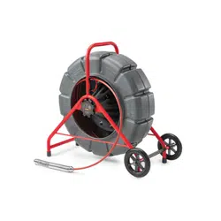
Use with SeeSnake
®
Inspection Equipment
The micro CA-350 Inspection Camera can
also be used with various SeeSnake Inspec -
tion Equipment and is specifically designed
to be used with the microReel, microDrain™
and the nanoReel Inspection Systems. When
used with these types of equipment, it retains
all of the functionality described in this manual.
The micro CA-350 Inspection Camera can
also be used with other SeeSnake Inspection
Equipment for viewing and recording only.
For use with SeeSnake Inspection Equip -
ment, the imager head and any cable exten-
sions must be removed. For the microReel,
microDrain™, nanoReel and similar equip-
ment, see the operator’s manual for informa-
tion on proper connection and use. For other
SeeSnake Inspection Equipment (typically a
reel and monitor), an adapter must be used to
connect the micro CA-350 Inspection Camer a
to a Video-Out port on the SeeSnake Inspec -
tion Equipment. When connected in this man-
ner, the micro CA-350 Inspection Camera will
display the camera view and can be used for
recording.
When connecting to SeeSnake Inspection
Equipment (microReel, microDrain™, or nano -
Reel), align the interconnect module connected
to your reel with the cable connector on the
micro CA-350 Inspection Camera, and slide it
straight in, seating it squarely. (See Figure 18)
Figure 18 – Camera Connector Plug Installed
Do not twist the connector plug to
prevent damage.
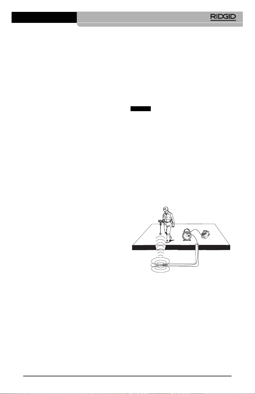
Locating the Sonde
If used with a sonde (In-Line Transmitter), the
sonde can be controlled two ways. If the reel is
equipped with a sonde key, that can be used to
turn the sonde ON and OFF. Otherwise, the
sonde is turned ON by decreasing LED bright-
ness to zero. Once the Sonde has been lo-
cated, the LEDs can be returned to their nor-
mal brightness level to continue the inspection.
A RIDGID locator such as the SR-20, SR-60,
Scout
®
, or NaviTrack
®
II set to 512 Hz can be
used to locate features in the drain being in-
spected.
Figure 19 – Locating the Reel Sonde
To locate the Sonde, turn the locator ON and
set it to Sonde mode. Scan in the direction of
the Sonde's probable location until the locator
detects the Sonde. Once you have detected
the Sonde, use the locator indications to zero
in on its location precisely. For detailed in-
structions on Sonde locating, consult the Oper -
ator's Manual for the locator model you are
using.
NOTICE
Maintenance
WARNING
Remove battery before cleaning.
• Always clean the imager head and cable
after use with mild soap or mild detergent.
• Gently clean the display screen with a
clean dry cloth. Avoid rubbing too hard.
• Use only alcohol swabs to clean the cable
connections.
• Wipe the hand held display unit down with
a clean, dry cloth.
Reset Function
If the unit stops functioning and does not op-
erate, press the Reset Button (under the left
side port cover – Figure 4). The unit may re-
cover to normal operation when re started.
Optional Equipment
WARNING
To reduce the risk of serious injury, only
use equipment specifically designed
and recommended for use with the
RIDGID micro CA-350 Inspection Camera
such as those listed below. Other equip-
ment suitable for use with other tools
may be hazardous when used with the
micro CA-350 Inspection Camera.
micro CA-350 Inspection Camera
14
For a complete listing of RIDGID equipment
avail able for this tool, see the Ridge Tool Cata -
log online at RIDGID.com or call Ridge Tool
Technical Services (800) 519-3456.
Storage
The RIDGID micro CA-350 Inspection Cam era
must be stored in a dry secure area between
-4°F (-20°C) and 140°F (60°C) and humidity
between 15% and 85% RH.
Store the tool in a locked area, out of the
reach of children and people unfamiliar with
the micro CA-350 Inspection Cam era.
Remove the battery before storage or ship-
ping.
Service and Repair
WARNING
Improper service or repair can make the
RIDGID micro CA-350 Inspection Camera
unsafe to operate.
Service and repair of the micro CA-350 In -
spec tion Camera must be performed by a
RIDGID In dependent Authorized Service
Center.
For information on your nearest RIDGID In -
depen dent Service Center or any service or
repair questions:
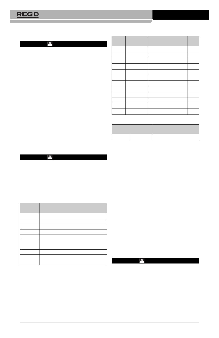
Catalog
No. Description
37108 3' (90 cm) Cable Extension
37113 6' (180 cm) Cable Extension
37103 Imager Head and Cable - 17 mm
37098 1 m length 6mm diameter imager
37093 4 m length 6mm diameter imager
37123 17 mm Accessory Pack (Hook,
Magnet, Mirror)
36758 AC Adapter
40623 Headset Accessory with
Microphone
Catalog Plug
No. Region Type
55193 Charger USA, Canada and Mexico A
55198 Charger Europe C
55203 Charger China A
55208 Charger Australia & Latin America I
55213 Charger Japan A
55218 Charger United Kingdom G
44798 Charger Cord North America A
44808 Charger Cord Europe C
44803 Charger Cord China A
44813 Charger Cord Australia & LA I
44818 Charger Cord Japan A
44828 Charger Cord United Kingdom G
Catalog
No. Model Capacity
55183 RB-1225 12V 2.5Ah
Batteries
All listed batteries will work with any catalog number RBC-121
Battery Charger.
RBC-121 Chargers and Cords

micro CA-350 Inspection Camera
15
• Contact your local RIDGID distributor.
• Visit RIDGID.com to find your local RIDGID
contact point.
• Contact Ridge Tool Technical Service De -
partment at rtctechservices@emerson.com,
or in the U.S. and Canada call (800) 519-
3456.
Disposal
Parts of the RIDGID micro CA-350 Inspection
Camera contain valuable materials and can be
recycled. There are companies that specialize
in recycling that may be found locally. Dispose
of the com ponents in compliance with all ap-
plicable regulations. Contact your local waste
management authority for more information.
For EC Countries: Do not dispose
of elec trical equipment with house-
hold waste!
According to the European Guide -
line 2012/ 19/EU for Waste Elec trical
and Electronic Equipment and its
imple men tation into national legislation, elec-
trical equipment that is no longer usable must
be collected separately and disposed of in
an environmentally correct manner.

micro CA-350 Inspection Camera
16
SYMPTOM POSSIBLE REASON SOLUTION
Display turns ON, but
does not show image.
LEDs on imager head
are dim at max bright-
ness, display switches
between black and
white, color display
turns itself OFF after a
brief period.
Unit will not turn ON.
Troubleshooting
Loose cable connections.
Imager is broken.
Imager head covered by debris.
Battery low on power.
Dead battery.
Unit need to be reset.
Check cable connections, clean if re-
quired. Re-attach.
Replace the Imager.
Visually inspect imager head to make
certain it is not covered by debris.
Replace battery with charged battery.
Replace with charged battery.
Reset unit. See “Maintenance” Section.

Caméra d’inspection
micro CA-350
micro CA-350
Caméra d’inspection micro CA-350
Notez ci-dessous et conservez le numéro de série indiqué sur la plaque signalétique de l’ap-
pareil.
N° de
série
AVERTISSEMENT
Familiarisez-vous avec ce mode
d’emploi avant d’utiliser l’appareil.
L’incompréhension ou le non respect
des consignes ci-devant augmenterait
les risques de choc électriques, d’in-
cendie et/ou de graves lésions cor-
porelles.

18
Caméra d’inspection micro CA-350
Table des matières
Symboles de sécurité.........................................................................................................19
Consignes générales de sécurité
Sécurité du chantier.........................................................................................................19
Sécurité électrique...........................................................................................................19
Sécurité individuelle.........................................................................................................19
Utilisation et entretien du matériel ...................................................................................20
Utilisation et entretien du bloc-piles.................................................................................20
Service après-vente.........................................................................................................20
Consignes de sécurité particulières
Sécurité de la caméra d’inspection micro CA-350...........................................................21
Description, caractéristiques techniques et équipements de base
Description ......................................................................................................................21
Caractéristiques techniques ............................................................................................22
Equipements de base......................................................................................................22
Commandes....................................................................................................................22
Enoncé de la FCC...............................................................................................................23
Compatibilité électromagnétique (EMC) ..........................................................................23
Icônes..................................................................................................................................24
Assemblage de l’appareil
Installation et remplacement des piles ............................................................................24
Alimentation sur secteur à l’aide du transformateur ........................................................24
Installation du câble de tête de caméra et de ses rallonges............................................25
Montage des accessoires................................................................................................25
Insertion de la carte SD
TM
................................................................................................25
Contrôle préalable de l’appareil........................................................................................25
Préparation de l’appareil et des lieux ...............................................................................26
Consignes d’utilisation......................................................................................................27
Ecran virtuel ....................................................................................................................27
Réglage de l’image..........................................................................................................28
Saisi des images .............................................................................................................29
Menu ...............................................................................................................................29
Chronomètre....................................................................................................................30
Langue ............................................................................................................................30
Date et heure...................................................................................................................30
Sortie télé ........................................................................................................................30
Mise à jour logiciel...........................................................................................................30
Haut-parleur ....................................................................................................................30
Arrêt automatique............................................................................................................30
Retour aux paramètres d’origine .....................................................................................30
Exposé ............................................................................................................................30
Transfert d’images vers ordinateur ..................................................................................30
Raccordement télé ..........................................................................................................30
Utilisation du matériel d’inspection SeeSnake
®
......................................................................31
Entretien
Réarmement....................................................................................................................32
Accessoires ........................................................................................................................32
Stockage .............................................................................................................................32
Service après-vente ...........................................................................................................32
Recyclage............................................................................................................................33
Dépannage..........................................................................................................................34
Garantie à vie ..................................................................................................Page de garde
*Traduction de la notice originale
Caméra d’inspection micro CA-350
19
Symboles de sécurité
Des symboles et mots clés spécifiques, utilisés à la fois dans ce mode d’emploi et sur l’ap-
pareil lui-même, servent à signaler d’importants risques de sécurité. Ce qui suit permettra
de mieux comprendre la signification de ces mots clés et symboles.
Ce symbole sert à vous avertir aux dangers physiques potentiels. Le respect des consignes qui
le suivent vous permettra d’éviter les risques de blessures graves ou mortelles.
Le terme DANGER signifie une situation dangereuse potentielle qui, faute d’être
évitée, provoquerait la mort ou de graves blessures corporelles.
Le terme AVERTISSEMENT signifie une situation dangereuse potentielle
qui, faute d’être évitée, serait susceptible d’entraîner la mort ou de graves
blessures corporelles.
Le terme ATTENTION signifie une situation dangereuse potentielle qui, faute d’être
évitée, serait susceptible d’entraîner des blessures corporelles légères ou modérées.
Le terme AVIS IMPORTANT signifie des informations concernant la protection des
biens.
Ce symbole indique la nécessité de lire le manuel soigneusement avant d’utiliser le matériel. Le
mode d’emploi renferme d’importantes informations concernant la sécurité d’utilisation du
matériel.
Ce symbole indique le port obligatoire de lunettes de sécurité intégrales lors de la manipu-
lation ou utilisation du matériel.
Ce symbole indique un risque d’écrasement des doigts ou des mains par les mécanismes
de l’appareil.
Ce symbole indique un risque de choc électrique.
Sécurité électrique
• Evitez tout contact avec les objets reliés
à la terre tels que canalisations, radia-
teurs, cuisinières et réfrigérateurs. Tout
contact avec la terre augmenterait les
risques de choc électrique.
• N’exposez pas l’appareil à la pluie ou
aux intempéries. Toute pénétration d’eau
à l’intérieur d’un appareil électrique aug-
menterait les risques de choc électrique.
Sécurité individuelle
• Soyez attentif, faites attention à ce que
vous faites et faites preuve de bon sens.
N’utilisez pas d’appareil électrique lorsque
vous êtes sous l’influence de drogues, de
l’alcool ou de médicaments. Lors de l’utili-
sation d’un appareil électrique, un instant
d’inattention risque d’entraîner de graves
lésions corporelles.
• Ne vous mettez pas en porte-à-faux.
Maintenez une bonne position de travail
et un bon équilibre à tout moment. Cela
vous permettra de mieux contrôler l’ap -
pareil en cas d’imprévu.
• Prévoyez les équipements de protec-
tion individuelle nécessaires. Portez sys-
tématiquement une protection oculaire. Le
Consignes générales de
sécurité
AVERTISSEMENT
Familiarisez-vous avec l’ensemble du
mode d’emploi. Le non-respect des con-
signes d’utilisation et de sécurité ci-
après augmenterait les risques de choc
électrique, d’incendie et/ou de grave
blessure corporelle.
CONSERVEZ CES INSTRUCTIONS !
Sécurité du chantier
• Assurez-vous de la propreté et du bon
éclairage des lieux. Les zones encom-
brées ou mal éclairées sont une invitation
aux accidents.
• N’utilisez pas d’appareils électriques en
présence de matières explosives telles
que liquides, gaz ou poussières com-
bustibles. Les appareils électriques pro-
duisent des étincelles susceptibles d’en-
flammer les poussières et émanations com-
bustibles.
• Eloignez les enfants et les spectateurs
lors de l’utilisation d’un appareil élec-
trique. Les distractions risquent de vous
faire perdre le contrôle de l’appareil.
AVIS IMPORTANT
DANGER
AVERTISSEMENT
ATTENTION

20
Utilisation et entretien du
bloc-piles
• N’utilisez que le type de chargeur in-
diqué par le fabricant. Les chargeurs
prévus pour un certain type de bloc-piles
peuvent augmenter les risques d’incendie
s’ils sont utilisés sur un type de bloc-piles
différent.
• N’utilisez que les bloc-piles spécifique-
ment prévus pour cet appareil. L’emploi
d’autres types de bloc-piles augmenterait
les risques d’accident et d’incendie.
• Rangez tout bloc-piles non-utilisé à l’é-
cart d’objets métalliques tels que trom-
bones, pièces de monnaie, clés, clous,
vis ou autres petits objets métalliques
qui seraient susceptibles de créer une
connexion entre ses deux bornes. Un
court-circuit entre les bornes du bloc-piles
pourrait provoquer des brûlures ou un in-
cendie.
• Sous conditions abusives, il y a risque
de projection de l’électrolyte contenu
dans le bloc-piles ; éviter tout contact.
En cas de contact accidentel, rincez la
peau à grande eau. En cas de contact
avec les yeux, consultez un médecin de
surcroit. L’électrolyte projeté par le bloc-
piles risque de provoquer des irritations
ou des brûlures.
Révisions
• Confiez toute révision éventuelle de ce
matériel à un réparateur qualifié garan-
tissant l’utilisation exclusive de pièces
de rechange identiques aux pièces
d’ori gine. Cela assurera la sécurité de
l’appareil.
Consignes de sécurité
spécifiques
AVERTISSEMENT
La section suivante contient d’im por -
tantes consignes de sécurité qui s’ad -
ressent spécifiquement à la caméra
d’inspection.
Afin de limiter les risques de choc élec-
trique ou autres blessures graves, lisez
le mode d’emploi soigneusement avant
d’utiliser la caméra d’inspection micro
CA-350.
CONSERVEZ CES INSTRUCTIONS !
port d’un masque à poussière, de chaus-
sures de sécurité antidérapantes, d’un
casque de chantier ou de protecteurs d’or-
eilles s’impose lorsque les conditions l’ex-
igent.
Utilisation et entretien du
matériel
• Ne forcez pas l’appareil. Prévoyez l’ap -
pareil approprié en fonction des travaux
envisagés. L’appareil approprié fera le tra-
vail plus efficacement et avec un plus
grand niveau de sécurité lorsqu’il tourne au
régime prévu.
• N’utilisez pas d’appareil électrique dont
l’interrupteur ne contrôle pas la mise en
marche ou l’arrêt. Tout appareil électrique
qui ne peut pas être contrôlé par son inter-
rupteur est dangereux et doit être réparé.
• Retirez les piles avant tout réglage, rem-
placement d’accessoires ou stockage
de l’appareil. De telles mesures préven-
tives limiteront les risques d’accident.
• Rangez tout appareil non utilisé hors de
la portée des enfants et des individus
qui n’ont pas été familiarisés avec ce
type de matériel ou son mode d’em-
ploi. Les appareils électriques sont dan-
gereux entre les mains d’utilisateurs non
initiés.
• Veillez à l’entretien de l’appareil. Ex -
aminez-le pour signes de grippage, de
bris et de toute autre anomalie qui ris-
querait de nuire à son bon fonction-
nement. Le cas échéant, faire réparer
l’appareil avant de l’utiliser. De nom-
breux accidents sont provoqués par des
appareils mal entretenus.
• Lors de l’utilisation de cet appareil et
de ses accessoires, respectez le mode
d’emploi ci-présent en tenant compte
des conditions de travail existantes.
L’utilisation de cet appareil à des fins
autres que celles prévues pourrait créer
des situations dangereuses.
• N’utilisez que les accessoires spéci-
fiquement désignés par le fabricant
pour votre type d’appareil. L’emploi d’ac-
cessoires prévus pour d’autres types d’ap-
pareil augmenterait les risques d’accident
grave.
• Assurez-vous de la parfaite propreté
des poignées de l’appareil. Cela assurera
une meilleure prise en main.
Caméra d’inspection micro CA-350

Caméra d’inspection micro CA-350
21
savonneuse. Ne pas manger ou fumer lors
de la manipulation ou utilisation de la
caméra d’inspection micro CA-350. Cela
aidera à éviter les risques de contamination
par contact avec des substances toxiques
ou infectieuses.
• Ne jamais utiliser la caméra d’in spec -
tion micro CA-350 lorsque vous avez
les pieds dans l’eau. L’utilisation d’un ap-
pareil électrique avec les pieds dans l’eau
augmenterait les risques de choc élec-
trique.
• Avant d’utiliser la caméra d’inspection
micro CA-350, familiarisez-vous avec :
– Le manuel ci-présent,
– Le manuel du chargeur,
– Les consignes d’utilisation visant tout
autre matériel associé à cet appareil.
Le non-respect de l’ensemble des con-
signes d’utilisation et de sécurité pourrait
entraîner des dégâts matériels et/ou de
graves lésions corporelles.
Au besoin, le présent manuel sera accom-
pagné de la Déclaration de conformité CE
(890-011-320.10) sous forme de livret indi-
viduel.
En cas de questions visant ce produit
RIDGID
®
:
– Consultez votre distributeur RIDGID.
– Visitez le site RIDGID.com pour localiser
l’interlocuteur le plus proche.
– Consultez les services techniques de
Ridge Tool par mail adressé à rtctechser-
vices@emerson.com ou en composant
le (800) 519-3456 (à partir des Etats-Unis
et du Canada exclusivement).
Description, caractéris-
tiques techniques et
équipements de base
Description
La caméra d’inspection numérique RIDGID
®
micro CA-350 est un puissant appareil d’ins -
pection vidéo portatif. Cette plate-forme en-
tièrement numérique vous permet d’effectuer
et d’enregistrer les inspections en format photo
ou vidéo dans les endroits difficilement ac-
cessibles. Plusieurs possibilités de manipula-
tion d’image (rotation d’image, zoom nu mé -
rique, etc.) sont incorporées au système pour
assurer des images à la fois détaillées et pré-
cises. L’appareil dispose également d’une mé-
La mallette de transport de la caméra d’in -
spection micro CA-350 est équipée d’un porte-
documents permettant de garder le mode
d’emploi de l’appareil à portée de main de
tout utilisateur éventuel.
Sécurité de la caméra d’inspec-
tion micro CA-350
• Ne pas exposer l’appareil à l’eau ou
aux intempéries. Cela augmenterait les
risques de choc électrique. La tête de
caméra et son câble sont étanches jusqu’à
une profondeur de 10 pieds (3 m). L’ap -
pareil lui-même ne l’est pas.
• Ne jamais introduire la caméra d’in -
spection micro CA-350 dans un endroit
qui risque de contenir des éléments
sous tension. Cela augmenterait les ris -
ques de choc électrique.
• Ne jamais introduire la caméra d’in -
spection micro CA-350 dans un endroit
qui risque de renfermer un mécanisme
quelconque. Cela augmenterait les
risques de blessure par entraînement.
• Ne pas utiliser cet appareil pour des
diagnostiques personnels ou médicaux
quelconques. Ceci n’étant pas un ap-
pareil médical, de telles utilisations pour-
raient s’avérer dangereuses.
• Prévoyez systématiquement les équipe -
ments de protection individuelle appro-
priés lors de la manipulation et l’uti -
lisation de la caméra d’inspection micro
CA-350. Les canalisations d’évacuation et
autres lieux d’inspection risquent de renfer-
mer des produits chimiques, des bactéries
ou autres substances potentiellement tox-
iques, infectieuses, irritantes ou autrement
dangereuses. Les équipe-ments de pro-
tection individuelle appropriés com-
prennent systématiquement les lunettes
et gants de sécurité, voire éventuelle-
ment des équipements supplémentaires
tels que gants en latex ou caoutchouc,
visières intégrales, lunettes fermées, vête-
ments de protection, appareils respiratoires
ou chaussures de sécurité blindées.
• Respectez les consignes d’hygiène.
Suite à toute manipulation ou utilisation
de la caméra d’inspection micro CA-350
dans des conduites ou autres endroits
susceptibles de renfermer des produits
chimiques ou des bactéries, lavez vos
mains ou autres parties du corps éven -
tuellement exposées avec de l’eau chaude

22
Équipements de base
La caméra d’inspection micro CA-350 est
livrée avec les éléments suivants :
• Appareil portable micro CA-350
• Tête de caméra Ø 17 mm
• Câble USB de 3' (90 cm)
• Câble RCA (avec audio) de 3' (90 cm)
• Crochet, aiment et miroir accessoires
• Bloc-piles Li-ion de 12V
• Chargeur Li-ion avec cordon d’alimentation
• Transformateur
• Casque d’écoute avec microphone
• Carte SD
TM
de 8 GB
• Mode d’emploi
Figure 1 – Caméra d’inspection micro CA-350
Commandes
Figure 2 – Commandes
moire externe et d’une sortie télé. Des acces-
soires de tête de caméra (miroir, crochet et
aimant) sont inclus pour augmenter la soup-
lesse du système.
Caractéristiques techniques
Application
recommandée .............Utilisation à l’in-
térieur
Distance visuelle .........de 0.4" (10 mm) à
l’infini
Affichage......................TFT couleur (résolu-
tion : 320 x 240) de
3.5" (90 mm)
Tête de caméra............3/4" (17mm)
Eclairage .....................4 LED réglables
Longueur de câble.......3' (0,90 m), jusqu’à
30' avec rallonges,
tête de caméra et
câble étanches
jusqu’à 10' (3 m),
IP67
Format photo...............JPEG
Résolution d’image......640 x 480
Format vidéo ...............MP4
Résolution vidéo..........640 x 480
Vitesse d’image...........jusqu’à 30
images/seconde
Sortie télé....................PAL ou NTSC au
choix
Mémoire interne ..........235 MB
Mémoire externe .........Carte SD
TM
de 32
GB maxi (8 GB
fournie)
Interfaces.....................Câble USB et carte
SD
TM
Température de
fonctionnement............de 32 à 113 °F
(0 à 45 °C)
Température de
stockage ......................de –4 à 140 °F
(-20 à 60 °C)
Alimentation..................Bloc-piles Li-ion
rechargeable de 12
volts, transformateur
12V/3A
Poids.............................5.5 lbs (2,5 kg)
Caméra d’inspection micro CA-350
Rotation
d’image
Menu
Retour
Marche/
Arrêt
Sélection/
Confirmation
Obturateur
Flèches

Caméra d’inspection micro CA-350
23
Si la mise en marche et l’arrêt de ce matériel
devait éventuellement déterminer qu’il pro-
duit des interférences nuisibles à la récep-
tion radio ou télévision locale, il est conseillé à
l’utilisateur d’essayer d’éliminer cette inter-
férence selon l’une ou plusieurs des méthodes
suivantes :
• Réorientez ou déplacez l’antenne de ré-
ception.
• IAugmentez la distance entre le matériel
et le récepteur.
• Consultez le concessionnaire ou un techni-
cien radio/télé compétent pour obtenir de
l’aide.
Compatibilité électro-
magnétique (EMC)
La compatibilité électromagnétique d’un pro-
duit sous-entend son bon fonctionnement en
présence d’irradiations électromagnétiques
et de décharges électrostatiques, sans inter-
férence électromagnétique de sa part vis-à-vis
des appareils environnants.
La caméra d’inspection
RIDGID micro CA-350 est conforme à l’ensem-
ble des normes EMC applicables. Cependant,
la possibilité d’un éventuel parasitage des ap-
pareils environnants ne peut pas être exclue.
Figure 3 – Branchements côté droit
Figure 4 – Branchements côté gauche
Avertissement FCC
Cet appareil a été testé et homologué au titre
des limites établies pour les dispositifs
numériques Catégorie B sous l’article 15 de la
réglementation FCC. Ces limites ont été éta -
blies afin d’assurer une protection raisonnable
contre les interférences nuisibles dans les in-
stallations résidentielles.
Ce matériel produit, utilise et risque d’émettre
des fréquences radio et, faute d’une installa-
tion et utilisation conforme aux instructions,
risque de produire des interférences nuisi-
bles aux communications radio.
Cependant, il n’est pas garanti qu’une telle in-
terférence n’aura pas lieu dans une installation
donnée.
Micro
incorporé
Fiche
secteur
Fiche
casque
Haut-
parleur
Sortie télé
Mini USB
Carte SD
TM
Remise à zéro
AVIS IMPORTANT
24
grave blessure corporelle en cours d’u-
tilisation de l’appareil.
Installation et remplacement
des piles
La pile de la micro CA-350 n’est pas installée
lors de la livraison de l’appareil. Si l’indicateur
de charge affiche , il sera nécessaire de
recharger la pile. Retirez le bloc-piles avant de
ranger l’appareil.
1. Comprimez les languettes du bloc-piles
(Figure 5). Au besoin, retirez la pile.tirez la
pile.
Figure 5 – Retrait/introduction de la pile
2. Introduisez la pile dans l’appareil, contacts
en premier.
Alimentation sur secteur
Il est également possible d’alimenter la caméra
d’inspection micro CA-350 sur secteur à l’aide
du transformateur fourni.
1. Ouvrez le couvercle des fiches du côté
droit de l’appareil (Figure 3).
2. Avec les mains sèches, branchez le
trans formateur sur la prise de courant.
3. Introduisez la fiche du transformateur
dans la prise cylindrique « DC 12V » de
l’appareil.
Figure 6 – Alimentation sur secteur
Icônes
Assemblage de l’appareil
AVERTISSEMENT
Respectez les consignes d’assemblage
suivantes afin de limiter les risques de
Caméra d’inspection micro CA-350
Indicateur de charge – Pile chargée à
100 %.
Indicateur de charge – Pile à 25 % de
charge.
Carte SD
TM
– Présence d’une carte SD.
Photo – Mode « photo » activé.
Vidéo – Mode « vidéo » activé.
Lecture – La sélection de cette icône per-
met de visualiser et/ou éliminer les im-
ages et vidéos sauvegardées.
Menu – La sélection de cette icône per-
met d’accéder au menu.
Sélection – A partir de la visualisation en
cours, la touche « sélection » permet de
revenir à l’écran de lecture.
Retour – A partir de la visualisation en
cours, la touche « retour » permet de nav-
iguer entre le mode vidéo et le mode photo.
Intensité LED – Les flèches droite et
gauche permettent de moduler l’intensité
lumineuse des LED.
Zoom – Les flèches haute et basse per-
mettent de moduler le zoom de 1x à 2x.
Sauvegardée – Indication que l’image ou
vidéo enregistrée a été sauvegardée.
Corbeille – Icône de confirmation d’ef-
facement.
Mode – Sélection du mode opératoire
(Photo/Vidéo/Lecture).
Horloge – Affichage ou dissimulation de
la date et de l’heure de l’enregistrement.
Langue – Choix de la langue d’affichage
(anglais, français, espagnol allemand, hol-
landais, italien, etc.).
Horodateur – Cet écran permet de fixer
la date et l’heure de l’enregistrement.
Télé – Sélection du format télé applicable
(NTSC ou PAL) au niveau de la sortie vidéo.
Mise à jour – Accès à la dernière mise à
jour du logiciel.
Haut-parleur/Micro – Interrupteur micro-
phone et haut-parleur en cours d’enreg-
istrement et de lecture.
Arrêt automatique – L’appareil s’éteint
automatiquement au bout de 5, 15 o 60
minutes d’inactivité.
Paramètres de base – Retour aux
paramètres d’origine de l’appareil.
A propos – Affichage de la version du
logiciel.
Installation de la carte SD
TM
Ouvrez le couvercle des fiches du côté gauche
de l’appareil (Figure 4) pour accéder au loge-
ment de carte SD. Introduisez la carte SD dans
le logement avec ses contacts orientés vers
vous et sa partie biaise vers le bas (Figure 9).
Ne forcez pas la carte, car elle ne peut être in-
troduite que dans ce sens. Lors qu’une carte SD
est installée, une petite icône de carte SD ap-
paraît en haut et à gauche de l’écran, en même
temps que le nombre d’images ou la longueur
de vidéo qu’elle peut contenir.
Figure 9 – Introduction de la carte SD
Contrôle préalable de
l’appareil
AVERTISSEMENT
Contrôlez l’état de la caméra d’in spec -
tion avant chaque utilisation afin de cor-
riger d’éventuelles anomalies et limiter le
risque de choc électrique, de blessure
corporelle et de détérioration de l’ap -
pareil.
1. Assurez-vous que l’appareil est éteint.
2. Retirez la pile afin de l’examiner pour
signes de détérioration. Au besoin, rem-
placez la pile. Ne jamais tenter d’ali -
menter l’appareil à l’aide d’une pile en-
dommagée.
3. Nettoyez soigneusement l’ensemble du
matériel. Cela facilitera à la fois son exa-
men et sa manipulation.
4. Examinez la caméra d’inspection micro
Branchement du câble de tête
de caméra et de ses rallonges
Avant de pouvoir utiliser la caméra d’in spec -
tion micro CA-350, il est nécessaire d’y bran -
cher le câble de tête de caméra. Pour ce faire,
alignez la clé de la fiche du câble sur l’ergot
correspondant de l’appareil (Figure 7). Une
fois que ces deux éléments sont bien en-
gagés, vissez manuellement la molette de
verrouillage du câble sans trop forcer.
Figure 7 – Connexion du câble
Des rallonges de câble de 3 pieds (90 cm) et
de 6 pieds (180 cm) de long sont disponibles
pour éventuellement atteindre une longueur
maximale de 30 pieds (9 m). Pour ajouter des
rallonges, dévissez la molette de verrouillage,
puis déconnectez le câble de tête de caméra
de l’appareil. Raccordez la rallonge de câble
comme indiqué plus haut (Figure 7). Ensuite,
engagez la clé du câble de tête de caméra
dans l’ergot de la fiche de la rallonge, puis ser-
rez la molette manuellement pour verrouiller la
connexion.
Montage des accessoires
Les trois accessoires livrés avec l’appareil
(crochet, aimant, miroir) se montent tous de la
même manière.
Figure 8 – Montage des accessoires
Pour monter un accessoire, tenez la tête de
caméra comme indiqué à la Figure 8, puis
engagez l’extrémité semi-circulaire de l’ac -
cessoire sur les plats de la tête. Ensuite,
tournez l’accessoire d’un quart de tour pour le
verrouiller.
Caméra d’inspection micro CA-350
25
Accessoire
1/4 tour
Méplats
26
CA-350 pour signes d’éléments endom-
magés, usés, manquants ou grippés,
voire pour toute anomalie susceptible de
nuire au bon fonctionnement et à la sécu-
rité de l’appareil.
5. Examinez la lentille de la tête de caméra
pour signes de condensation. Le cas
échéant, n’utilisez pas la caméra avant
que cette condensation ait eu le temps de
s’évaporer.
6. Examinez le câble sur toute sa longueur
pour signes de fissuration ou de détério-
ration. Un câble endommagé risque de
laisser pénétrer l’eau à l’intérieur de l’ap -
pareil et d’augmenter les risques de choc
électrique.
7. Assurez-vous du serrage adéquat des
connexions entre l’appareil, les rallonges
éventuelles et le câble de la tête de
caméra afin de garantir l’étanchéité de
l’ensemble. Vérifiez le bon assemblage de
l’ensemble.
8. Assurez-vous de la présence, de la bonne
fixation et de la lisibilité de l’étiquette sig-
nalétique de l’appareil (Figure 10).
Figure 10 – Etiquette signalétique
9. Si vous constatez une anomalie en cours
de l’examen, n’utilisez pas la caméra
d’inspection avant d’y avoir remédié.
10. Avec les mains sèches, réinstallez la pile.
11. Appuyez sur la touche marche/arrêt pen-
dant une seconde. L’éclairage de la tête
de caméra devrait alors s’allumer, et
l’écran d’accueil devrait apparaître. Dès
que l’appareil est prêt, l’image captée
en temps réel par la tête de caméra de-
vrait apparaître à l’écran. Si aucune
image n’apparaît, consultez le chapitre
Dépannage.
12. Appuyez à nouveau sur la touche mar -
che/arrêt pendant une seconde pour
éteindre l’appareil.
Préparation de
l’appareil et du chantier
AVERTISSEMENT
Préparez la caméra d’inspection micro
CA-350 et le chantier selon la procédure
suivante afin de limiter les risques de
choc électrique, d’entraînement ou autres
accidents, et éviter d’endom mager l’ap-
pareil ou le réseau.
1. Examinez les lieux pour :
• Un éclairage suffisant
• La présence de liquides, émanations
ou poussières inflammables qui ris-
querait d’exploser. Le cas échéant, ne
travaillez pas dans le secteur avant d’en
avoir identifié et éliminé les sources po-
tentielles. La caméra d’inspection micro
CA-350 n’est pas antidéflagrante et
risque d’émettre des étincelles.
• Un endroit au sec, de niveau, stable et
dégagé pour l’utilisateur. N’utilisez pas la
caméra d’inspection lorsque vous avez
les pieds dans l’eau.
2. Examinez l’endroit ou l’objet à inspecter
afin de déterminer si ou non la caméra
d’inspection micro CA-350 est adaptée à
l’intervention envisagée.
• Vérifiez les points d’accès de l’objet.
Le diamètre minimal nécessaire pour le
passage de la tête de caméra de 17
mm de diamètre est d’environ
3
/
4
(19
mm) po.
• Déterminez la distance jusqu’au point
d’inspection. Des rallonges peuvent être
ajoutées à la caméra pour atteindre une
distance maximale de 30 pieds (9 m).
• Déterminez s’il existe des obstacles qui
seraient susceptibles d’imposer des vi-
rages très serrés au câble. Le câble de la
caméra d’inspection est câble de né-
gocier des coudes d’un rayon maxi de 5
pouces (127 mm) sans être endom-
magé.
Caméra d’inspection micro CA-350

Caméra d’inspection micro CA-350
27
• Assurez-vous que l’objet à inspecter
n’est pas sous tension. Le cas échéant,
il sera nécessaire de couper le courant
dans cette zone afin de limiter les ris -
ques de choc électrique. Appliquez les
mesures de verrouillage appropriées
afin d’empêcher la remise en tension du
réseau en cours d’inspection.
• Evaluez les risques de rencontrer des
liquides en cours d’inspection. Le câble
et la tête de caméra sont étanches
jusqu’à une profondeur de colonne
d’eau de 10 pieds (3 m). Une profon deur
supérieure risque de provoquer des
fuites au niveau du câble ou de la tête
de caméra et augmenterait les risques
de choc électrique et de détérioration du
matériel. L’appareil lui-même bénéficie
d’une résistance à l’eau IP54, mais ne
doit pas être immergé.
• Établissez la présence éventuelle de
produits chimiques, notamment lors de
l’inspection des évacuations. Il faut se
familiariser avec les précautions d’us -
age applicables à chaque type de pro-
duit chimique rencontré. Consultez le
fabricant du produit chimique en ques-
tion pour les renseignements corre-
spondants. Aussi les produits chimiques
risquent-ils d’endommager la caméra
d’inspection.
• Déterminez la température ambiante et
celle des objets environnants. Se re-
porter aux caractéristiques techniques.
L’utilisation de l’appareil dans un en-
droit hors des limites de température
indiquées ou en contact avec des élé-
ments plus ou moins chauds que celles-
ci pourrait endommager la caméra.
• Déterminez si la zone à inspecter con-
tient des composants mécaniques. Le
cas échéant, ces éléments devront être
désactivés durant l’inspection afin de
réduire les risques d’enchevêtrement.
Appliquez les procédures de verrouil-
lage appropriées afin d’empêcher le
mouvement de ces mécanismes en
cours d’inspection.
Si la caméra d’inspection micro CA-350 n’est
pas adaptée aux travaux envisagés, consultez
le catalogue en ligne RIDGID.com pour la liste
complète des produits RIDGID.
3. Assurez-vous que la caméra d’inspec-
tion micro CA-350 a bien été correcte-
ment examinée.
4. Montez les accessoires adaptés à l’appli -
cation envisagée.
Utilisation de l’appareil
AVERTISSEMENT
Prévoyez systématiquement des lunettes
de sécurité afin de protéger vos yeux
contre la projection de débris.
Respectez le mode d’emploi de l’appareil
afin de limiter les risques de choc élec-
trique, enchevêtrement et autres acci-
dents.
1. Assurez-vous que la caméra d’inspec-
tion et le chantier ont été correctement
préparés et qu’il n’y a pas de spectateurs
ou autres sources de distraction sur les
lieux.
2. Appuyez sur la touche marche/arrêt pen-
dant deux secondes. L’éclairage de la tête
de caméra devrait s’allumer, suivi de l’af-
fichage de l’écran d’accueil. Cet écran
restera apparent le temps de l’initialisation
de l’appareil, puis sera remplacé par
l’écran vidéo affichant l’image captée en
temps réel par la tête de caméra.
Figure 11 – Ecran d’accueil
(A noter que la version sera mise à
jour à chaque mise à jour du logiciel).
Ecran vidéo
La majeure partie de l’inspection se fait sur
l’écran vidéo. Celui-ci affiche l’image captée par
la tête de caméra en temps réel. Cet écran per-
met à la fois de zoomer, de régler l’intensité des
LED, et d’importer les images et vidéos cap-
tées.
En haut de l’écran se trouve une barre d’état

indiquant le mode opératoire utilisé, tandis
que la barre d’information en bas de l’écran af-
fiche l’état de la pile, l’heure, la date et la
présence éventuelle d’une carte SD
TM
.
Figure 12 – Ecran vidéo
Lors de sa mise sous tension, la caméra d’in-
spection se met par défaut en mode « photo ».
Vous pouvez appuyez sur la touche « menu »
à tout moment pour accéder au menu. Le
menu sera superposé sur l’image vidéo. Ser -
vez-vous des flèches horizontales pour
changer de mode opératoire. Servez-vous des
flèches verticales pour naviguer parmi les
options au menu, puis appuyez sur la touche
« Sélection » pour arrêter votre choix.
Figure 13 – Affichage de sélection de mode
opératoire
3. Si les autres paramètres de la caméra
d’inspection (horodateur, langue, date et
heure, sortie télé, mise à jour de logiciel,
haut-parleur/microphone, arrêt automa-
tique, remise aux paramètres de base)
doivent être réglés à leur tour, veuillez
vous reporter au chapitre Menu.
4. Avant d’introduire la tête de caméra dans
la zone visée, il sera parfois nécessaire de
préformer son câble afin de franchir les
coudes ou obstacles potentiels. Ne ja-
mais tenter de couder le câble sur un
rayon inférieur à 5", car cela pourrait l’en-
28
dommager. Lors des inspections effec-
tuées dans des endroits sombres, al-
lumez les LED avant d’y introduire la tête
de caméra.
Ne jamais forcer le câble lors de son
insertion ou retrait, car cela pourrait en-
dommager à la fois l’appareil et la zone
inspectée. Ne jamais utiliser la tête de
caméra pour modifier ou dégager son
propre passage ou dégager des obsta-
cles éventuels ; voire en tant qu’autre
chose qu’un appareil d’inspection. Cela
risquerait d’endommager l’appareil élec-
trique ainsi que la zone inspectée.
Réglage de l’image
Réglage de l’éclairage LED : Avec l’écran
en mode « vidéo », appuyez sur les flèches
horizontales pour augmenter ou diminuer
l’éclairage LED. Un témoin d’intensité d’é -
clairage sera affiché à l’écran pendant le
réglage.
Figure 14 – Réglage des LED
Zoom : La caméra d’inspection micro CA-
350 dispose d’un zoom numérique de 2x.
Avec l’écran en mode « vidéo », appuyez sur
les flèches verticales pour rapprocher ou
éloigner l’image. Un témoin de zoom sera af-
fiché à l’écran pendant le réglage.
Figure 15 – Réglage du zoom
Caméra d’inspection micro CA-350
Barre
d’état
Barre
d’information

Menu
Vous pouvez appuyez sur la touche « menu »
à tout moment pour accéder au menu. Le
menu se superposera sur l’écran vidéo. A par-
tir du menu, l’utilisateur peut soit changer de
mode opératoire ou accéder au menu des
paramètres.
Le menu des paramètres affiche plusieurs
catégories (Figure 17) de choix. Les flèches
horizontales permettent d’aller d’une caté-
gorie à l’autre. Les flèches verticales per-
mettent de naviguer parmi les articles affichés.
La catégorie sélectionnée sera encadrée en
rouge vif. Une fois que le paramètre voulu est
atteint, appuyez sur la touche « sélection »
pour appliquer ce choix. Toute modification
est automatiquement sauvegardée.
Lorsque vous êtes en mode « menu », vous
pou vez appuyer sur la touche « retour »
pour revenir à l’écran précédent ou sur la
touche « menu » pour sortir du menu et
retrouver l’écran vidéo.
Figure 17 – Menu des paramètres
Mode « relecture »
1. Pour revoir un enregistrement à partir de
l’écran en cours, appuyez sur la touche
« sélection » . Sélectionnez ensuite
soit « Photo » ou « Vidéo » pour revoir le
fichier souhaité. Le mode « re lecture » est
l’interface des fichiers sauvegardés. Il ira
par défaut au dernier fichier enregistré.
2. Lors de la relecture de photos, l’utilisateur
aura la possibilité de parcourir toutes les
images sauvegardées, d’effacer une
image quelconque et d’afficher les infor-
mations jointes au fichier.
3. Lors de la relecture d’une vidéo, l’utili -
sateur aura la possibilité de naviguer
parmi les différentes vidéos, les arrêter,
les relancer et les supprimer. A noter
qu’en l’absence d’une carte SD™, l’uti -
Rotation d’image : Il est possible, au besoin,
de faire tourner l’image (photo ou vidéo) en
sens anti-horaire par tranches de 90° à la fois
en appuyant sur la touche de rotation d’im -
age .
Capture d’image
Capture de photos
Avec l’écran en mode « vidéo » et l’icône
« photo » allumée en haut et à gauche de
l’écran, appuyez sur la touche « obturateur »
pour prendre une photo des lieux. Une icône
de sauvegarde apparaîtra momentané-
ment à l’écran pour indiquer que la photo
saisie a été sauvegardée dans la mémoire
interne de l’appareil ou sur sa carte SD
TM
.
Capture de vidéos
Avec l’écran en mode « vidéo » et l’icône
« vidéo » allumée en haut et à gauche de
l’écran, appuyez sur la touche « obturateur »
pour lancer l’enregistrement vidéo. Un cadre
rouge clignotera autour de l’icône « vidéo »
pendant tout l’enregistrement, et la durée de
l’enregistrement sera affichée en haut de l’écran.
Appuyez à nouveau sur la touche « obtura -
teur » pour arrêter l’enregistrement. La sauveg-
arde de la vidéo dans la mémoire interne de
l’appareil peut prendre quelques secondes.
La micro CA-350 est équipée d’un ensemble
microphone/haut-parleur incorporé qui per-
met d’enregistrer et de réécouter d’éventuels
commentaires accompagnant l’enregistrement
vidéo. Un casque d’écoute avec microphone
est prévu pour éventuellement se substituer à
l’ensemble audio incorporé à l’appareil. Ce
casque se branche dans la prise audio située
sur le flanc droit de la caméra.
5. Lorsque l’inspection est terminée, retirez
précautionneusement la tête de caméra
de la zone inspectée.
Figure 16 – Ecran en mode « vidéo »
Caméra d’inspection micro CA-350
29

30
lisateur ne pourra qu’accéder aux im-
ages et vidéos de la mémoire interne de
l’appareil.
Effacement des fichiers
Pour effacer une image ou une vidéo
à partir du mode « relecture », appuyez
sur la touche « menu ». Le dialogue de
con firm ation permet à l’utilisateur d’ef-
facer les fichiers inutiles. L’icône activée est
alors encadrée de rouge. La navigation se
fait à l’aide des flèches .
Vignette horaire
Celle-ci permet d’afficher ou de masquer
l’heure et la date de l’enregistrement.
Langue
Sélectionner l’icône de langue dans le menu,
puis appuyez sur « sélection ». Parcourez les
diverses langues offertes à l’aide des flèches
verticales , puis appuyez à nouveau sur
« sélection » pour arrêter votre choix .
Date et Heure
Sélectionnez « Date » ou « Heure » pour met-
tre ces paramètres à jour. Sélectionnez
« Format Date » ou « Format Heure » pour
modifier leur affichage.
Sortie télé
Sélectionner « NTSC » ou « PAL » en fonction
du format du téléviseur utilisée. L’écran de
l’appareil s’éteindra et l’image sera transmise
au téléviseur. Pour obtenir une image en temps
réel sur l’appareil, appuyez sur la touche
marche/arrêt et interrompre le transfert
d’image.
Mise à jour de logiciel
Utiliser la « mise à jour de logiciel » pour télé -
charger la version la plus récente du logiciel.
Ce logiciel devra être téléchargé sur une carte
SD™ avant d’être introduit dans l’ap pareil.
Toutes mises à jour éventuelles seront dis -
ponibles sur www.RIDGID.com.
Haut-parleur
Sélectionnez l’icône du haut-parleur à partir du
menu, puis appuyez sur « sélection » .
Sélectionnez « marche » ou « arrêt » à l’aide
des flèches verticales pour allumer ou
éteindre le haut-parleur pendant la relecture de
la vidéo.
Arrêt automatique
Sélectionnez l’icône d’arrêt automatique, puis
appuyez sur « sélection » . Sélectionnez
« désactiver » pour neutraliser la fonction d’ar -
rêt automatique. Sélectionnez « 5 minutes »,
« 15 minutes » ou « 60 minutes » pour que
l’ap pareil s’éteigne automatiquement au bout
de 5, 15 ou 60 minutes d’inactivité. A noter
que la fonction d’arrêt automatique sera tempo-
rairement neutralisée lors de l’enregistrement
ou la relecture d’une vidéo.
Retour aux paramètres
d’origine
Sélectionnez l’icône de retour aux paramètres
d’origine, puis appuyez sur « sélection » .
Con firmez votre choix en sélectionnant « Oui »,
puis en appuyant à nouveau sur « sélection »
. L’appareil reviendra ainsi aux paramètres
du fabricant.
A propos
Sélectionnez la fonction « A propos » (About)
pour afficher la version actuelle du logiciel
micro CA-350, ainsi que les licences et paten -
tes applicables.
Transfert d’images vers un
ordinateur
Avec l’appareil en marche, connectez le micro
CA-350 à l’ordinateur via un câble USB. La
présence de cet écran sera alors affichée sur
celui du micro CA-350. La mémoire interne
et, le cas échéant celle de la carte SD™, ap-
paraîtront en tant que fichiers distincts sur
l’ordi nateur, désormais accessibles en tant
qu’unités de stockage USB standards. Cela
permet de copier ou d’effacer les fichiers à
partir de l’ordinateur.
Connexion télé
Le câble RCA fourni permet de raccorder la
caméra d’inspection micro CA-350 à un télé -
viseur ou autre moniteur afin de relire ou enreg-
istrer les images à distance.
Ouvrez le couvercle des prises du côté droit de
l’appareil (Figure 3), puis introduisez le câble
RCA dans la sortie télé. Introduisez l’autre ex-
trémité du câble dans la prise du téléviseur
ou moniteur. Assurez-vous d’avoir sélec-
tionné le format vidéo (NTSC ou PAL) ap-
proprié. Il sera éventuellement nécessaire de
modifier aussi la source de l’émission avant de
Caméra d’inspection micro CA-350
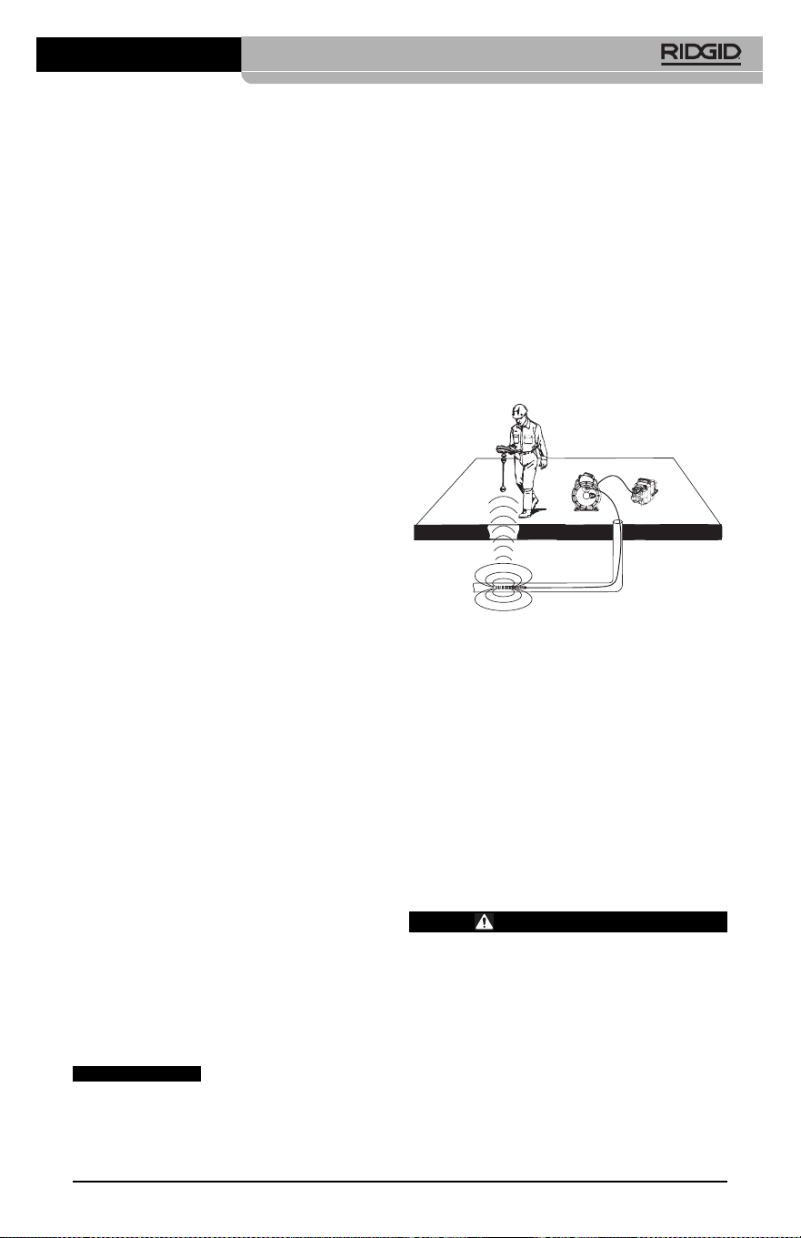
Localisation de la sonde
Lors de l’utilisation d’une sonde (transmetteur
souterrain) avec l’appareil, cette sonde peut
être contrôlée de deux manières. Si l’enrouleur
est équipé d’une clé de sonde, celle-ci permet
d’activer et de désactiver la sonde. Sinon, la
sonde doit être activée en diminuant l’intensité
de l’éclairage LED jusqu’à zéro. Une fois la
sonde localisée, les LED peuvent être remises
à leur intensité initiale afin de poursuivre l’in-
spection.
Un localisateur RIDGID du type SR-20, SR-60,
Scout
®
ou NaviTrack
®
II réglé à 512 Hz peut
servir à localiser les divers caractéristiques
de la conduite inspectée.
Figure 19 – Localisation de la sonde de l’en-
rouleur
Pour localiser la sonde, allumez le localisateur
et mettez-le en mode « Sonde ». Balayez le sol
en direction de la position probable de la sonde
jusqu’à ce que le localisateur la détecte. Une
fois la sonde repérée, servez-vous des indica-
tions fournies par le détecteur pour cibler sa
position précise. Pour de plus amples ren-
seignements concernant la localisation des
sondes, consultez le mode d’emploi du local-
isateur utilisé.
Entretien
AVERTISSEMENT
Retirez la pile de l’appareil avant toute
intervention.
• Nettoyez la tête de caméra et son câble
systématiquement après chaque utilisa-
tion à l’aide d’un savon ou d’un détergeant
non agressif.
• Nettoyez délicatement l’écran de l’appareil
à l’aide d’un morceau de tissu doux et
propre. Evitez de trop frotter.
Caméra d’inspection micro CA-350
31
pouvoir visualiser l’image. Choisissez le for-
mat de sortie télé approprié au Menu.
Utilisation des accessoires
d’inspection SeeSnake
®
La caméra d’inspection micro CA-350 est com-
patible avec plusieurs types de systèmes d’in-
spection SeeSnake, notamment les systèmes
microReel, microDrain
TM
et nanoReel. Lorsqu’il
est utilisé avec ce type de matériel, l’appareil
retient toutes les fonctions décrites dans le
présent manuel. La caméra d’in spec tion micro
CA-350 peut également utiliser d’au tres types
de matériel d’inspection SeeSnake, mais ses
fonctions seront alors limitées à la relecture et
à l’enregistrement.
Pour utiliser un système SeeSnake avec l’ap -
pareil, il sera d’abord nécessaire de déposer la
tête de caméra (ainsi que ses rallonges éven -
tuelles) de l’appareil. Lors de l’uti lisation des
systèmes microReel, microDrain™, nanoReel
ou systèmes similaires, consultez leur mode
d’emploi pour les consignes de raccordement
et d’utilisation. Pour l’utilisa tion d’autres types
de matériel d’inspection SeeSnake (enrouleurs,
moniteurs, etc.), il sera nécessaire de prévoir
un adaptateur pour raccorder la caméra d’in-
spection micro CA-350 au matériel d’inspection
SeeSnake. Une fois ainsi raccordée, la caméra
d’in spection micro CA-350 permettra d’afficher
et d’enregistrer les images émises.
Lors de la connexion de l’appareil à du mat -
ériel d’inspection SeeSnake
®
(microReel,
microDrain™ ou nanoReel), branchez le mod-
ule de connexion de l’enrouleur sur la connex-
ion de câble de la caméra d’inspection micro
CA-350 en l’alignant parfaitement (Figure 18).
Figure 18 – Connexion du câble de tête de
caméra
La fiche de connexion est
fragile ; ne jamais la vriller lors de son introduc-
tion.
AVIS IMPORTANT
• Nettoyez les connexions de câble exclu-
sivement avec des tampons imbibés d’al -
cool.
• Essuyez le boîtier de l’appareil avec un
morceau de tissu sec et propre.
Réarmement
Si l’appareil cesse de fonctionner, appuyez sur
la touche de réarmement qui se trouve sous le
couvercle de prises gauche (Figure 4) en es-
pérant que cela suffira à lui rendre sa fonction-
nalité lorsqu’il est rallumé.
Accessoires
AVERTISSEMENT
Seuls les accessoires suivants ont été
conçus pour fonctionner avec la caméra
d’inspection micro CA-350. Toute tenta-
tive d’adaptation à la caméra d’inspec -
tion micro CA-350 d’accessoires prévus
pour d’autres types d’appareils risque
de s’avérer dangereuse.
Caméra d’inspection micro CA-350
Pour obtenir la liste complète des acces-
soires RIDGID prévus pour cet appareil, con-
sultez le catalogue Ridge Tool en ligne à
RIDGID.com ou consultez les services tech-
niques de Ridge Tool en composant le (800)
519-3456.
Stockage
La caméra d’inspection micro CA-350 doit
être stockée dans un endroit sec et sous clé à
une température ambiante de -4 °F (-20 °C) à
140 °F (60 °C) et une humidité relative de 15
à 85 %.
Rangez l’appareil, son bloc-piles, son char geur
et ses câbles dans un local sous clé, hors
de la portée des enfants et de tout individu
non familiarisé avec la caméra d’in spection
micro CA-350.
Retirez le bloc-piles avant le remisage ou l’ex-
pédition de l’appareil.
Service après-vente et
réparations
AVERTISSEMENT
Toute intervention mal exécutée risque
de rendre la caméra d’inspection RIDGID
micro CA-350 dangereuse.
Toute révision ou réparation de la caméra
d’inspection micro CA-350 doit être confiée à
un réparateur RIDGID agréé.
Pour localiser le centre d’entretien le plus
proche ou poser une question visant le serv-
ice après-vente de l’appareil :
• Consultez votre distributeur RIDGID
• Visitez le site RIDGID.com pour localiser
l’interlocuteur le plus proche.
• Consultez les services techniques de
Ridge Tool par mail adressé à rtctechser-
vices@emer son.com ou, à partir des USA
32
Réf.
catalogue Description
37108 Rallonge de câble de 3 pieds (90 cm)
37113 Rallonge de câble de 6 pieds (90 cm)
37103 Tête de caméra Ø 17 mm avec câble
37098 Câble de tête de caméra Ø 6 mm (1 m)
37093 Câble de tête de caméra Ø 6 mm (4 m)
37123 Pack d’accessoires Ø 17 mm (miroir,
crochet et aiment)
36758 Transformateur de courant
40623 Casque d’écoute avec micro
Réf. Type de
catalogue Région fiche
55193 Chargeur USA, Canada, Mexique A
55198 Chargeur Europe Continentale C
55203 Chargeur Chine A
55208 Chargeur Australie, I
Amérique Latine
55213 Chargeur Japon A
55218 Chargeur Royaume Uni G
44798 Cordon Amérique du Nord A
d’alimentation
44808 Cordon Europe Continentale C
d’alimentation
44803 Cordon Chine A
d’alimentation
44813 Cordon Australie, I
d’alimentation Amérique Latine
44818 Cordon Japon A
d’alimentation
Chargeurs et cordons d’alimentation pour
RBC-121
Réf. Type de
catalogue Région fiche
44828 Cordon Royaume Uni G
d’alimentation
Réf.
catalogue Modèle Capacité
55183 RB-1225 12V 2,5Ah
Bloc-piles
Toutes les piles répertoriées peuvent être rechargées par tout
chargeur de la série RB-121.

Caméra d’inspection micro CA-350
33
et du Canada exclusivement, en
composant le (800) 519-3456.
Recyclage
Certains composants de la caméra d’in spec -
tion micro CA-350 contiennent des matières
de valeur susceptibles d’être recyclées. Il se
peut que certaines des entreprises de recy-
clage concernées se trouvent localement.
Disposez de ces composants selon la régle-
mentation en vigueur. Pour de plus amples
renseignements, consultez votre centre de
recyclage local.
A l’attention des pays de la CE :
Ne jamais jeter de matériel élec-
trique à la poubelle !
Selon la norme européenne 2012/ -
19/EU visant les déchets de ma -
tériel électrique et électronique et
son application vis-à-vis de la législation na-
tionale, tout matériel électrique non utilisable
doit être collecté à part et recyclé d’une
manière écologiquement responsable.

34
Caméra d’inspection micro CA-350
SYMPTÔMES CAUSES POSSIBLES SOLUTIONS
L’écran s’allume mais
ne montre pas d’im-
age.
L’éclairage de la tête de
caméra est sombre
même à pleine puis-
sance, l’écran oscille
entre le noir et le blanc,
l’écran couleur s’éteint
en peu de temps.
L’appareil ne s’allume
pas.
Dépannage
Mauvaise connexion des câbles.
Tête de caméra endommagée.
Tête de caméra recouverte de débris.
Pile déchargée.
Pile morte.
L’appareil a besoin d’être réarmé.
Vérifier les connexions de câble et les
nettoyer si nécessaire avant de les re-
brancher.
Remplacer la tête de caméra.
S’assurer que la tête de caméra n’est
pas encrassée.
Remplacer la pile par une pile chargée.
Remplacer la pile par une pile chargée.
Réarmer l’appareil selon les consignes
de la section « Entretien ».

Cámara de inspección
micro CA-350
microCA-350
Cámara de inspección micro CA-350
Apunte aquí el número de serie del aparato, que se encuentra en su placa de características.
N° de
serie
ADVERTENCIA
Antes de utilizar este aparato, lea
detenidamente su Manual del
Operario. Pueden ocurrir descargas
eléctricas, incendios y/o graves le-
siones si no se comprenden y siguen
las ins truc ciones de este manual.

36
Cámara de inspección micro CA-350
Índice
Simbología de seguridad...................................................................................................37
Seguridad general
Seguridad en la zona de trabajo .....................................................................................37
Seguridad eléctrica..........................................................................................................37
Seguridad personal .........................................................................................................37
Uso y cuidado del aparato...............................................................................................38
Uso y cuidado de la batería.............................................................................................38
Servicio............................................................................................................................38
Seguridad específica
Seguridad de la Cámara de inspección micro CA-350....................................................39
Descripción, especificaciones y equipo estándar
Descripción......................................................................................................................39
Especificaciones..............................................................................................................39
Equipo estándar ..............................................................................................................40
Mandos............................................................................................................................40
Comunicado de la FCC (Federal Communications Commission de los EE.UU.) ..............41
Compatibilidad electromagnética (CEM) .........................................................................41
Íconos..................................................................................................................................41
Ensamblaje del aparato
Instalación y reemplazo de la batería..............................................................................42
Alimentación con el adaptador CA ..................................................................................42
Instalación del cable del formador de imágenes y de cables de extensión.....................42
Acoplamiento de accesorios ...........................................................................................42
Instalación de una tarjeta SD™.......................................................................................43
Inspección previa al funcionamiento ...............................................................................43
Preparación del aparato y de la zona de trabajo .............................................................44
Instrucciones de funcionamiento .....................................................................................45
Pantalla en vivo ...............................................................................................................45
Ajuste de la imagen.........................................................................................................46
Toma de imágenes ..........................................................................................................46
Menú ...............................................................................................................................47
Indicación visual de fecha y hora ....................................................................................47
Idioma..............................................................................................................................48
Fecha y hora ...................................................................................................................48
Salida de TV (TV Out) .....................................................................................................48
Actualización del Firmware..............................................................................................48
Altavoz.............................................................................................................................48
Apagado automático........................................................................................................48
Vuelta a la configuración de fábrica.................................................................................48
Acerca de ........................................................................................................................48
Transferencia de imágenes a una computadora..............................................................48
Conexión a TV .................................................................................................................48
Utilización con equipos de inspección SeeSnake
®
.................................................................48
Mantenimiento
Función de re-alistar........................................................................................................49
Equipo opcional .................................................................................................................50
Almacenamiento.................................................................................................................50
Servicio y reparaciones.....................................................................................................50
Eliminación del equipo ......................................................................................................50
Resolución de problemas..................................................................................................52
Garantía de por vida...................................................................................carátula posterior
*Traducción del manual original
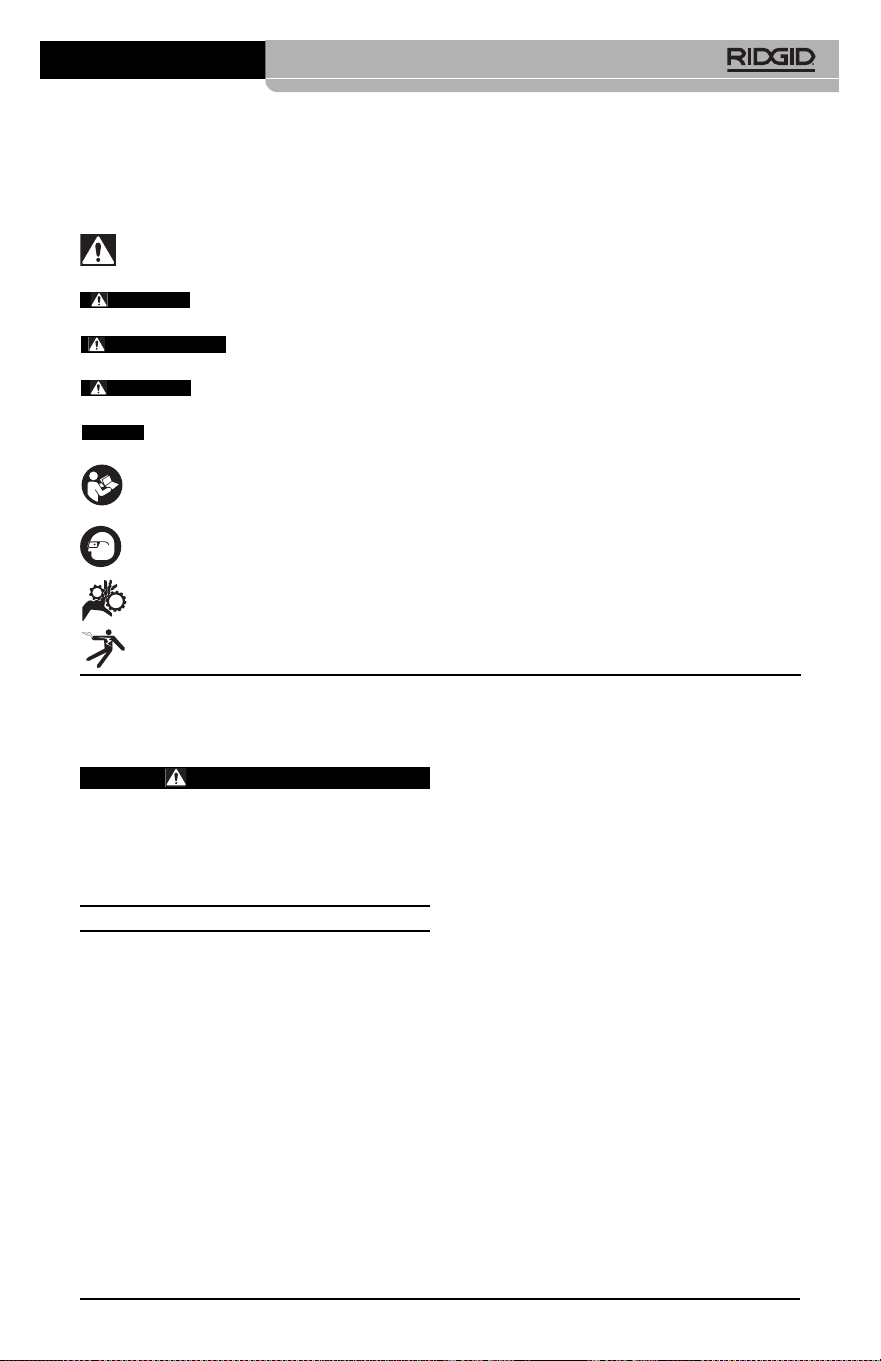
Cámara de inspección micro CA-350
37
Simbología de seguridad
En este manual del operario y en el aparato mismo encontrará símbolos y palabras de ad-
vertencia que comunican importante información de seguridad. Para su mejor comprensión,
en esta sección se describe el significado de estos símbolos.
Este es el símbolo de una alerta de seguridad. Sirve para prevenir al operario de las lesiones
corporales que podría sufrir. Obedezca todas las instrucciones que acompañan a este símbolo
de alerta para evitar lesiones o muertes.
Este símbolo de PELIGRO advierte de una situación de riesgo o peligro que, si no se
evita, ocasionará la muerte o graves lesiones.
Este símbolo de ADVERTENCIA advierte de una situación de riesgo o peligro
que, si no se evita, podría provocar muertes o lesiones graves.
Este símbolo de CUIDADO previene de una situación de riesgo o peligro que, si no se
evita, podría ocasionar lesiones leves o menores.
Un AVISO advierte de la existencia de información relacionada con la protección de un bien
o propiedad.
Este símbolo significa que, antes de usar el equipo, es necesario leer detenidamente su ma -
nual del operario. Este manual contiene importante información acerca del funcionamiento
apropiado y seguro del equipo.
Este símbolo señala que durante la manipulación y el funcionamiento de este aparato, con
el fin de evitar lesiones oculares, el operario debe ponerse siempre anteojos o gafas de se-
guridad con viseras laterales.
Este símbolo indica que el aparato en uso, sus engranajes y piezas movibles, pueden
aplastar manos, dedos u otras partes de su cuerpo.
Este símbolo advierte que podrían ocurrir descargas eléctricas.
Seguridad eléctrica
• Evite el contacto de su cuerpo con arte-
factos conectados a tierra tales como
cañerías, radiadores, estufas o cocinas,
y refrigeradores. Aumenta el riesgo de
que se produzca una descarga eléctrica
cuando su cuerpo ofrece conducción a
tierra.
• No exponga el aparato a la lluvia o a la
humedad. Cuando a un aparato le entra
agua, aumenta el riesgo de que se produz-
can descargas eléctricas.
Seguridad personal
• Manténgase alerta, preste atención a
lo que está haciendo y use sentido
común cuando trabaje con cualquier
aparato. No lo use si está cansado o se
encuentra bajo la influencia de drogas, al-
cohol o medicamentos. Sólo un breve de-
scuido mientras hace funcionar un aparato
puede resultar en lesiones graves.
• No trate de extender su cuerpo para al-
canzar algo. Mantenga sus pies firmes
en tierra y un buen equilibrio en todo
momento. Así se ejerce mejor control
sobre la herramienta en situaciones ines-
peradas.
Información de
seguridad general
ADVERTENCIA
Lea todas las instrucciones y adverten-
cias. Pueden ocurrir golpes eléctricos,
incendios y/o lesiones graves si no se si -
guen y respetan las instrucciones y ad-
vertencias detalladas a continuación.
¡GUARDE ESTAS INSTRUCCIONES!
Seguridad en la zona de trabajo
• Mantenga su área de trabajo limpia y
bien iluminada. Las zonas desordenadas
u oscuras pueden provocar accidentes.
• No haga funcionar el aparato en atmós-
feras explosivas, es decir, en presencia
de líquidos, gases o polvo inflama bles.
El aparato podría generar chispas que
pueden inflamar estos combustibles.
• Mientras haga funcionar este equipo,
apártese de niños y transeúntes. Cual -
quier distracción puede hacerle perder el
control del aparato.
AVISO
PELIGRO
ADVERTENCIA
CUIDADO

38
este modo usted no perderá el control sobre
la herramienta.
Uso y cuidado de la batería
• Cargue la batería solamente con el car-
gador especificado por el fabricante.
Un cargador apropiado para un tipo de
batería podría causar un incendio si se
usa con otro tipo de batería.
• Use el equipo solamente con la batería
específicamente designada. El uso de
cualquier otra batería podría causar incen-
dio y lesiones.
• Cuando no use la batería, manténgala
alejada de otros objetos metálicos como
monedas, llaves, clavos, tornillos, sujeta-
papeles o cualquier otro objeto metáli co
pequeño que podría formar un puen te
entre un borne y otro. Un cortocircuito
entre los bornes de la batería podría causar
un incendio y quemaduras.
• Si se maltrata la batería, podría expulsar
líquido. No toque el líquido. Si accidental-
mente ocurriera algún contacto, lave la
zona expuesta con agua. Si el líquido le en-
trara en los ojos, consulte a un médico. El
líquido expulsado de la batería puede
causar irritación o quemaduras.
Servicio
• El servicio de este equipo debe en-
comendarse a técnicos calificados que
empleen únicamente repuestos legíti-
mos. Sólo así se garantiza la continua se-
guridad de la herramienta.
Información de
seguridad específica
ADVERTENCIA
Esta sección entrega información de se-
guridad específica para esta cámara de
inspección.
Antes de utilizar la Cámara de inspec-
ción micro CA-350 de RIDGID
®
, lea estas
instrucciones detenidamente para pre-
venir choques eléctricos y otras lesiones
de gravedad.
¡GUARDE ESTAS INSTRUCCIONES!
El maletín de la Cámara de inspección micro
CA-350 cuenta con un compartimiento espe-
cial para conservar este manual al alcance
del operario.
• Use el equipo de protección personal
que corresponda. Siempre use protec-
ción para sus ojos. Al ponerse mascarilla
para el polvo, calzado de seguridad anti-
deslizante, casco o protección para los
oídos, según las circunstancias, usted evi-
tará lesionarse.
Uso y cuidado del aparato
• No fuerce el aparato. Use el equipo co-
rrecto para el trabajo que se dispone a
realizar. El aparato adecuado hará el tra-
bajo mejor y de manera más segura, a la
velocidad para la cual fue diseñado.
• Si el interruptor del aparato no lo en-
ciende o no lo apaga, no utilice el apa-
rato. Cualquier herramienta que no pueda
ser controlada mediante su interruptor
constituye un peligro y debe ser reparada.
• Desconecte la batería del aparato antes
de efectuarle ajustes, cambiarle acce-
sorios o almacenarlo. Estas medidas pre-
ventivas reducen el riesgo de accidentes y
lesiones.
• Almacene los aparatos eléctricos que
no estén en uso fuera del alcance de
niños y no permita que los hagan fun-
cionar personas sin capacitación o que
no hayan leído estas instrucciones. Las
herramientas son peligrosas en manos de
inexpertos.
• Hágale al aparato el mantenimiento de-
bido. Revise que no le falten piezas y que
no tenga partes quebradas o deterioradas
que podrían afectar su buen funciona -
mien to. Si está dañado, antes de usarlo,
hágalo componer. Los equipos en malas
condiciones causan numerosos acciden -
tes.
• Utilice el aparato y sus accesorios en
conformidad con estas instrucciones,
teniendo en cuenta las condiciones im-
perantes y las tareas que realizará.
Cuando se emplea una herramienta para
efectuar trabajos que no le son propios,
se crean situaciones peligrosas.
• Emplee únicamente los accesorios que
han sido recomendados por el fabri-
cante para usarse con este aparato. Los
accesorios aptos para un cierto equipo
pueden tornarse peligrosos si se utilizan en
conjunción con otros equipos.
• Mantenga todos los mangos del aparato
secos y limpios, sin grasa o aceite. De
Cámara de inspección micro CA-350

Cámara de inspección micro CA-350
39
• Antes de hacer funcionar una cámara
de inspección micro CA-350, debe leer y
entender:
– Este manual del operario.
– El manual de la batería y cargador.
– Las instrucciones para cualquier otro
equipo usado con este aparato.
Pueden producirse daños a la propiedad
y/o lesiones graves si no se respetan todas
las instrucciones y advertencias.
El folleto de la Declaración de Conformidad de
la Comunidad Europea (890-0011-320.10)
vendrá adosado a este manual cuando se
requiera.
Si tiene cualquier pregunta acerca de este
producto RIDGID
®
:
– Contacte al distribuidor RIDGID en su lo-
calidad.
– Visite RIDGID.com para averiguar dónde
se encuentran los centros autorizados de
RIDGID más cercanos.
– Llame al Departamento de Servicio Téc -
nico de Ridge Tool desde EE.UU. o
Canadá al (800) 519-3456 o escriba a
Descripción,
especificaciones y
equipo estándar
Descripción
La Cámara de inspección micro CA-350 de
RIDGID es un poderoso dispositivo portátil
de grabación digital. Constituye una completa
plataforma digital que permite realizar inspec-
ciones y grabar imágenes y videos en zonas
de difícil acceso. El sistema trae incorporadas
varias características para el manejo de las
imágenes, tales como rotación de imagen y
zoom digital, que permiten lograr inspecciones
visuales detalladas y precisas. El aparato
cuenta con memoria externa y salida de TV.
Incluye tres accesorios -gancho, imán y es-
pejo- que se conectan al cabezal de la cámara
para realizar múltiples tareas.
Especificaciones
Para uso ......................bajo techo
Distancia visible...........0,4" (10 mm)
hasta ∞
Visualizador.................TFT 3,5" (90 mm)
en colores (resolu-
ción 320 x 240)
Seguridad de la cámara de
inspección micro CA-350
• No exponga el visualizador al agua o
llu via. Si le llegase a entrar agua, podría
ocasionar descargas eléctricas. El for-
mador de imágenes de la micro CA-350 y
su cable son a prueba de agua hasta los 10
pies (3 m). El visualizador, en cambio, no lo
es.
• No ponga la Cámara de inspección mi -
cro CA-350 en sitio alguno que pu diera
estar bajo tensión o con corriente. Esto
aumenta los riesgos de que ocurran des -
cargas eléctricas.
• No ponga la Cámara de inspección
micro CA-350 en sitios donde haya pie -
zas en movimiento. Podría enredarse en
ellas y lesionarlo.
• Jamás use este aparato para realizar
una auscultación corporal o médica.
Éste no es un instrumento médico y podría
causar lesiones.
• Emplee siempre el equipo de protec-
ción personal adecuado cuando uti lice
la Cámara de inspección micro CA-350.
Los desagües y las zonas aledañas po-
drían contener sustancias químicas, bac-
terias u otras materias que podrían resul-
tar tóxicas, infecciosas, o causar que-
maduras u otras lesiones. Al hacer fun-
cionar este equipo, póngase siempre
ga fas o anteojos de seguridad y guan -
tes –ya sea de látex o de goma-, y otros
protectores como visera facial, ropa de
seguridad, respiradores y/o calzado con
punteras de acero.
• Mantenga una buena higiene. Después
de usar la Cámara de inspección micro
CA-350 para inspeccionar cañerías que
podrían contener sustancias químicas o
bacterias, lávese sus manos y las otras
partes de su cuerpo que hayan quedado
expuestas al contenido del desagüe, con
agua caliente y jabón. No coma ni fume
mientras manipula la Cámara de inspec-
ción micro CA-350. Así evita contaminarse
con materiales tóxicos o infecciosos.
• No opere la Cámara de inspección micro
CA-350 si el operario o el aparato están
parados en agua. Ocu rren descargas eléc-
tricas cuando se hace funcionar un aparato
eléctrico estando en contacto con agua.

40
• cargador de baterías de ion Li y cordón
• adaptador para CA
• auriculares con micrófono
• tarjeta SD™ de 8 GB
• manual del operario
Figura 1 – Cámara de inspección micro CA-350
Mandos
Figura 2 – Mandos
Figura 3 – Puertos del lado derecho
Cámara........................3/4" (17 mm)
Iluminación ..................4 LED regulables
Alcance del cable...........3 pies (0,9 m), posi-
ble de alargar a 30
pies (9 m) con ex ten -
siones opciona les. El
formador de imáge -
nes y el cable son a
prueba de agua
hasta los 10 pies
(3 m), IP67.
Formato de fotografía...JPEG
Resolución
fotográfica....................640 x 480
Formato de video ........MP4
Resolución
videográfica .................640 × 480
Velocidad
de cuadros...................hasta 30 FPS
TV-Out.........................PAL/NTSC elegible
por el usuario
Memoria incorporada...235 MB de memoria
Memoria externa .........tarjeta SD™ de 32
GB máx (8 GB
suministrados)
Salida de datos............cable USB y tarjeta
SD™
Temperaturas de
funcionamiento............32° a 113°F
(0° a 45°C)
Temperaturas de
almacenamiento..........- 4° a 140°F
(-20° a 60°C)
Fuente de
alimentación ................Batería de ion Li de
12 V; adaptador de
CA de 12 V y 3 A.
Peso..............................5,5 libras (2,5 kg)
Equipo estándar
La Cámara de inspección micro CA-350
viene con los siguientes artículos:
• visualizador de mano micro CA-350
• formador de imágenes 17 mm
• cable USB, de 3 pies (90 cm)
• cable RCA con audio, de 3 pies (90 cm)
• accesorios: gancho, imán y espejo
• batería de ion Li de 12 V
Rotación
de imagen
Menú
Volver atrás
Encendido
Seleccionar/
Confirmar
Obturador
Flechas
Micrófono
integrado
Adaptador
CA
Enchufe
hembra para
auriculares
Altavoz
Cámara de inspección micro CA-350
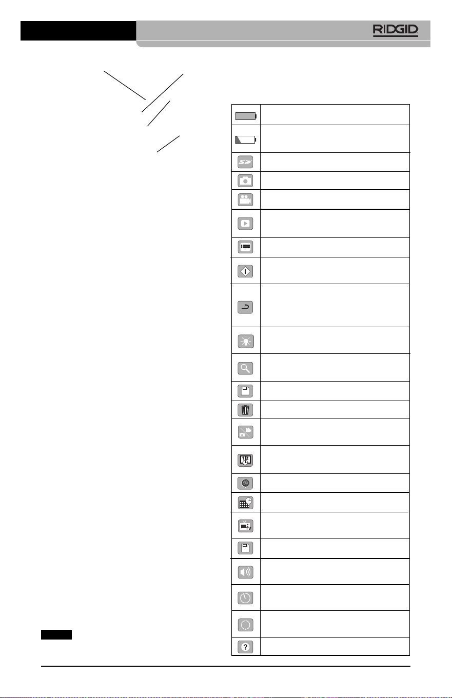
Figura 4 – Puertos del lado izquierdo
Comunicado de la FCC
Este equipo se ha sometido a pruebas y se
estima en conformidad con los límites im-
puestos a los aparatos digitales Categoría B,
según la Sección 15 de la Reglamentación
FCC. Estos límites han sido fijados con el fin
de asegurar una protección razonable contra
las interferencias en un medio residencial.
Este aparato genera, utiliza y puede irradiar
energía de radiofrecuencia y, si no se instala
y usa según las instrucciones, podría causar
interferencias perjudiciales a las comunica-
ciones de radio.
Sin embargo, es imposible garantizar que en
una cierta instalación no ocurrirán interferen -
cias.
Si este equipo efectivamente causa interferen-
cias perjudiciales sobre la recepción de radio
o televisión, las que pueden detectarse apa-
gando y encendiendo el aparato, el usuario
deberá tratar de eliminar la interferencia inten-
tando una o más de las siguientes acciones:
• Reorientar o reubicar la antena receptora.
• Alejar aún más el aparato del receptor.
• Consultar al distribuidor o a un técnico cali -
ficado de radio y televisión.
Compatibilidad electro-
magnética (CEM)
Se entiende por compatibilidad electromag-
nética la capacidad del producto para fun-
cionar sin problemas en un entorno donde se
encuentran presentes radiaciones electro-
magnéticas y descargas electroestáticas y
sin ocasionarle interferencia electromagnética
a otros equipos.
La Cámara de inspección micro CA-
350 de RIDGID cumple con todas las nor-
mas CEM pertinentes. Sin embargo, no se
TV-Out
Mini-enchufe
USB
Ranura
para tarjeta-
memoria
SD™
Botón de Reset
(re-alistar)
Cámara de inspección micro CA-350
41
puede descartar del todo la posibilidad de
que cause interferencias en otros dispositivos.
Íconos
Indicador de carga completa en la
batería: batería totalmente cargada.
Indicador de carga restante en la
batería: a la batería le resta un 25% de
su carga.
Tarjeta-memoria SD™: indica que una
tarjeta SD está puesta en el aparato.
Fotografía: indica que el aparato está
funcionando en modalidad de foto.
Filmación: indica que el aparato está
funcionando en modalidad de video.
Modalidad de reproducción: pulsan do
este ícono es posible ver o eliminar fo -
tos o videos guardados anteriormente.
Menú: pulsando este ícono se accede
a la pantalla Menú.
Seleccionar: al pulsar Seleccionar
desde la pantalla en vivo, se accede a
la pantalla de Reproducción.
Vuelta atrás: al pulsar Vuelta atrás
desde la pantalla en vivo, se cambia
entre Fotografía y Filmación. También
se utiliza para salir del Menú o de la
modalidad de Reproducción.
Luminosidad de los LED: se regulan
mediante las flechas izquierda y
derecha .
Zoom: oprima las flechas ascendente y
descendente para ajustar el zoom de
1,0x a 2,0x.
Guardar: indica que la foto o video ha
sido guardado en la memoria.
Papelera: para eliminar elementos.
Modalidad: permite seleccionar entre
fotografía, filmación de video o repro-
ducción.
Indicación visual de fecha y hora:
pulse este ícono para mostrar u ocultar
la fecha y hora en la pantalla.
Idioma: elija entre inglés, francés, es-
pañol, alemán, holandés, italiano, etc.
Hora y fecha: ingrese a esta pantalla
para anotar la fecha y la hora.
TV: seleccione entre los sistemas de
codificación de color NTSC o PAL para
habilitar el formato de salida de video.
Actualización del firmware: utilícelo
para actualizar el software del aparato.
Altavoz/Micrófono: enciende o apaga el
altavoz y micrófono mientras se graba o
reproduce un video.
Apagado automático: el aparato se
apagará automáticamente transcurridos
5, 15 o 60 minutos de inactividad.
Vuelta a las posiciones predetermi-
nadas de fábrica: restablece la configu-
ración inicial del aparato.
Acerca de: muestra la versión de soft-
ware en uso.
AVISO

Ensamblaje del aparato
ADVERTENCIA
Reduzca el riesgo de sufrir lesiones
graves durante el uso de este aparato
ensamblándolo correctamente.
Instalación y reemplazo de la
batería
La micro CA-350 no viene con su batería ins -
talada. Si el indicador de la carga de la batería
se muestra , la batería necesita recargarse.
Extraiga la batería antes de guardar el aparato.
1. Presione los clips (ver Figura 5) y jale
para extraer la batería.
Figura 5 – Extracción e instalación de la
batería
2. Introduzca el extremo de contacto de la
batería cargada en el aparato, como se
muestra en la Figura 5.
Alimentación con
el adaptador CA
La Cámara de inspección CA-350 también
funciona con corriente alterna mediante el
adaptador de CA provisto.
1. Abra la tapa que cubre los puertos del
lado derecho del aparato (Figura 3).
2. Con sus manos secas, enchufe el adap-
tador a un tomacorriente.
3. Introduzca el enchufe cilíndrico en el
puerto marcado “DC 12V”.
42
Figura 6 – Alimentación del aparato con el
adaptador CA
Instalación del cable del
formador de imágenes y de
cables de extensión
Es imprescindible que el cable del formador
de imágenes se encuentre conectado al vi -
sua lizador de mano para poder utilizar la
Cámara de inspección micro CA-350. Alinee la
clavija del conector del cable con la ranura en
el conector hembra del visualizador (Figura 7).
Introdúzcala hasta adentro y sólo ahora en-
rosque a mano la perilla estriada, para asen-
tar la conexión.
Figura 7 – Conexión del cable al visualizador
Hay disponibles extensiones para el cable,
de 3 y de 6 pies (90 cm y 180 cm) de largo,
para que usted pueda alcanzar con la cá-
mara una distancia de hasta 30 pies (9 m).
Para agregarle una extensión, primero de-
sconecte el cable fuera del visualizador, aflo-
jando la perilla estriada. Luego conecte la
extensión al visualizador como se describe
más arriba (Figura 7). Introduzca el extremo
con clavijas del cable dentro del conector
hembra en el extremo de la extensión y con
sus dedos enrosque la perilla estria da para
asentar la conexión.
Acoplamiento de accesorios
Los tres accesorios incluidos –espejo, gan-
cho e imán- se acoplan al formador de imá-
genes de la misma manera.
Sostenga el formador de imágenes como se
muestra en la Figura 8. Monte el extremo se -
Cámara de inspección micro CA-350
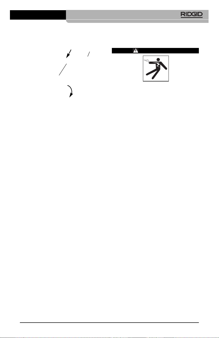
micircular del accesorio por sobre las caras
planas del formador de imágenes. Gire el ac-
cesorio en un cuarto de vuelta para retener lo.
Figura 8 – Acoplamiento de un accesorio
Instalación de una
tarjeta-memoria SD™
Abra la tapa que cubre los puertos del lado
izquierdo del aparato (Figura 4) para acceder
a la ranura de la tarjeta SD. Introduzca la tarjeta
SD en la ranura cuidando de que los contactos
apunten hacia usted y que la parte angular de
la tarjeta quede boca abajo (Figura 9). La tar-
jeta SD sólo puede entrar de una manera,
así es que no la fuerce. Instalada la tarjeta-
memoria, aparecerá -en la esquina superior
izquierda de la pantalla- el pequeño ícono
que representa a la tarjeta SD. Asimis mo,
aparecerá el número de imágenes o duración
de video que todavía es posible almacenar en
la tarjeta.
Figura 9 – Introducción de la tarjeta SD
Cámara de inspección micro CA-350
43
Inspección previa al
funcionamiento
ADVERTENCIA
Antes de cada uso, revise la Cámara de
inspección y corrija los problemas, para
reducir el riesgo de lesiones graves por
descargas eléctricas u otras causas, y
para no dañar el aparato.
1. Asegure que el aparato se encuentra
apagado.
2. Extraiga la batería y revísela por si mues-
tra daños. Reemplace la batería si es
necesario. No emplee la Cámara de ins -
pección si la batería está averiada.
3. Quite todo aceite, grasa o suciedad del
aparato. Así se facilita su inspección y
se evita que el aparato resbale de sus
manos.
4. Revise la Cámara de inspección micro
CA-350 para asegurar que no tenga pie -
zas quebradas, desgastadas, faltantes o
trabadas, o cualquier otra condición que
pueda impedir su funcionamiento normal
y seguro.
5. Revise el lente de la cámara por si mues-
tra condensación. No haga funcionar la
cámara -para que no se dañe- si se ha
formado condensación al interior de su
lente. Permita que el agua se evapore
antes de ponerla en funcionamiento.
6. Inspeccione toda la longitud del cable,
asegure que no esté dañado ni agrietado.
Por un cable dañado podría entrarle agua
al aparato y aumentar el riesgo de que
ocurran descargas eléctricas.
7. Asegúrese de que todas las conexiones
entre el visualizador de mano, cables de
extensión y el cable del formador de imá-
genes se encuentren apretadas. Todas
las conexiones deben estar firmemente
acopladas para que el cable se man-
tenga impermeable. Cerciórese de que el
aparato está correctamente ensamblado.
8. Revise que la etiqueta de advertencias
esté presente, bien pegada y legible
(Figura 10).
Accesorio
1/4 de vuelta
Cara plana
44
Figura 10 – Etiqueta de advertencias
9. Si detecta cualquier anomalía durante la
inspección, no utilice la cámara de in-
spección hasta que no haya sido debida-
mente reparada.
10. Con sus manos secas, vuelva a colocar la
batería en su compartimiento.
11. Oprima el botón de encendido y mantén -
galo oprimido durante un segundo. Las
luces del formador de imágenes deben
encenderse, y a continuación debería
surgir la pantalla de inicio. Cuando la cá-
mara esté lista, aparecerá en la pantalla la
imagen en vivo, es decir, lo que la cá-
mara se encuentra “viendo”. Consulte la
sección Resolución de problemas de
este manual si no aparece una imagen.
12. Oprima el botón de encendido y man-
téngalo oprimido por un segundo para
apagar la Cámara.
Preparación del aparato
y de la zona de trabajo
ADVERTENCIA
Prepare la Cámara de inspección micro
CA-350 y la zona de trabajo de acuerdo a
los siguientes procedimientos con el fin
de prevenir lesiones por descargas eléc-
tricas, enganches u otras causas, y
daños al aparato.
1. Revise que la zona de trabajo:
• esté bien iluminada,
• no tenga líquidos, vapores o polvo in-
flamables que puedan provocar un in-
cendio. Si estos combustibles están
pre sentes, no trabaje en la zona hasta
que hayan sido retirados. La Cámara de
inspección micro CA-350 no es a prue -
ba de explosión y puede generar chis-
pas.
• tenga un lugar nivelado, estable y seco
para situar al operario. No use el apa -
rato si está parado en agua.
2. Revise la zona o el espacio que inspec-
cionará y establezca si la Cámara de
inspección micro CA-350 es el equipo
que verdaderamente necesita para efec-
tuar la tarea que se propone realizar.
• Determine cuáles son los puntos de
acceso al espacio que inspeccionará. El
cabezal de la cámara, de 17 mm, cabe
por un hueco no menor a
3
/
4
pulgada
(19 mm) de diámetro.
• Establezca cuánto debe recorrer el
cable para alcanzar el área que se
ins peccionará. Pueden agregársele
extensiones al cable para que llegue
hasta los 30 pies (9 m).
• Determine si el cable deberá sortear
obstáculos que le exijan curvarse en
exceso. El cable de la cámara puede
efectuar un radio de curvatura máximo
de 5" (127 mm) sin sufrir daños.
• Establezca si es que en la zona de ins -
pección existe algún suministro eléc-
trico. De ser así, deberá apagarse el
suministro para evitar descargas eléctri-
cas. Tome las medidas adecuadas –blo-
queo y clausura de seguridad- para
evitar que otros vayan a conectar o
“dar la luz” durante la inspección.
• Determine si en la zona de inspección
podría haber algún líquido. El cable y el
cabezal formador de imágenes son a
prueba de agua hasta una profundidad
de 10 pies (3 m). A mayor profundidad,
al cable y al formador de imágenes
pue de entrarles agua. Esto podría cau -
sar descargas eléctricas o daños al
aparato. El visualizador es resistente al
agua (IP54), pero no debe sumer gírsele
en un líquido.
• Determine si la zona de inspección con-
tiene compuestos químicos, particular-
mente dentro de desagües. Es suma-
mente importante estar consciente de
las medidas de seguridad específicas
que deben seguirse para trabajar en
Cámara de inspección micro CA-350
2. Oprima y mantenga oprimido el botón
de encendido por dos segundos. Deben
encenderse las luces del formador de
imágenes, luego aparecerá la pantalla
de inicio. La pantalla le indica que el dis-
positivo se está cargando. Se ha car-
gado por completo cuando en pantalla
aparece la imagen en vivo desde la cá-
mara.
Figura 11 – Pantalla de inicio
(la versión del software cambiará tras
cada actualización del firmware).
Pantalla en vivo
La mayor parte de su trabajo lo realizará en la
pantalla del visualizador. Frente a sus ojos ya
está la imagen en vivo de lo que se encuentra
percibiendo la cámara. Usted puede hacer un
zoom in o zoom out, ajustar la luminosidad de
los LED y tomar fotos o un video desde esta
pantalla.
La pantalla exhibe, en la franja informativa
superior, la modalidad (foto o video) en que se
encuentra puesto el aparato, zoom, el ícono de
tarjeta-memoria SD™ (si en el aparato hay
una dentro), memoria disponible y alta voz/mi -
crófono encendido o apagado.
Figura 12 – Pantalla en vivo
Al encenderse la Cámara de inspección, la
modalidad predeterminada de imagen –la que
aparece primero- es la de imagen fija o fotos.
En cualquier instante usted puede acceder al
menú oprimiendo el botón de Menú. Cuando el
menú se haya superpuesto en la pantalla en
presencia de cualquier sustancia quí -
mica. Obtenga la información pertinente
del fabricante de la sustancia química.
Los compuestos químicos pueden dañar
o deteriorar la cámara de inspección.
• Mida la temperatura de la zona y los ob-
jetos que se encuentran en ella. Vea
las Especificaciones. La cámara po-
dría dañarse si funciona a temperat-
uras fuera de los límites especificados o
en contacto con objetos más calientes o
fríos que estos límites.
• Examine la zona que va a inspeccionar
para determinar si en ella hay piezas en
movimiento. Si es así, estas piezas de -
ben detenerse durante la inspección
para impedir que la cámara se enrede
en ellas. Tome las medidas adecuadas
–bloqueo y clausura de seguridad-
para evitar que, durante la inspección,
otros pongan las piezas detenidas nue-
vamente en movimiento.
Si la cámara de inspección micro CA-350 no es
la herramienta adecuada para cumplir con la
tarea por delante, RIDGID ofrece otros equipos
de inspección. Obtenga un listado completo
de los productos RIDGID en el catálogo
RIDGID, en línea en RIDGID.com.
3. Antes de usarla, asegure que ha revisado
la Cámara de inspección micro CA-350
correctamente.
4. Acóplele el accesorio adecuado para
cada tarea en particular.
Instrucciones de
funcionamiento
ADVERTENCIA
Use siempre protección para sus ojos,
para que no les entren mugre u otros
cuerpos extraños.
Siga las instrucciones de funcionamiento
con el fin de reducir el riesgo de descar-
gas eléctricas, enganches y otros que
puedan lesionarlo.
1. Asegure que la cámara de inspección y la
zona de trabajo han sido bien preparadas
y que por las inmediaciones no circulan
transeúntes ni existen distracciones.
Cámara de inspección micro CA-350
45
Franja
informativa
Fecha y
hora

46
vivo, emplee las flechas izquierda y derecha
para ingresar a la categoría MODE (moda -
lidades). Navegue con las flechas ascendente
y descendente para desplazarse entre los
diversos elementos del menú y pulse Se -
leccionar a su gusto.
Figura 13 – Selección de modalidades en
pantalla
3. Si desea cambiar las otras posiciones de
configuración que ofrece esta Cámara de
inspección (tales como Indicador de fecha
y hora, Idioma, Fecha y hora, TV Out ,
Actualización del firmware, Altavoz/micró -
fono, Apagado automático, Vuelta a las
posiciones predeterminadas de fábrica)
consulte la sección Menú.
4. Prepare la cámara para efectuar una ins -
pección. Es posible que se requiera curvar
el cable para lograr acceder y mirar en el
espacio que se inspeccionará. No curve el
cable a menos de 5 pulgadas radio; po-
dría dañarse. Si inspeccionará un espacio
oscuro, encienda los LED antes de in-
troducir la cámara y el cable en la zona de
inspección.
No ejerza excesiva fuerza para introducir
o retraer el cable; podría causar daños al
aparato y en la zona que se inspecciona.
No utilice el cable o el cabezal del for-
mador de imágenes como un arma o
herramienta para modificar el entorno o
despejar obstáculos. Se corre el riesgo
de causar daños al aparato o en el área
de inspección.
Ajuste de la imagen
Ajuste de la luminosidad de los LED: es-
tando en la pantalla en vivo, oprima los bo -
tones de flecha derecha e izquierda para
incrementar o disminuir la luminosidad de los
LED. El indicador o barra de la luminosidad se
mostrará en la pantalla mientras usted efec-
túa el ajuste.
Figura 14 – Ajuste de los LED
Zoom: La Cámara de inspección micro CA-
350 cuenta con un zoom digital de 3,5x. Para
hacer un zoom in o un zoom out emplee las
flechas arriba y abajo mientras tenga a su
vista la pantalla en vivo. El indicador o barra
del zoom se mostrará en la pantalla mientras
usted acerca o aleja la imagen.
Figura 15 – Ajuste del zoom
Rotación de la imagen: la imagen en pan-
talla (foto o video) puede rotarse de a 90°
hacia la izquierda oprimiendo el botón de
Rotación de la imagen .
Toma de imágenes
Toma de imagen fija o foto
Estando en la pantalla en vivo, asegúrese de
que el ícono de cámara fija o foto está
presente en la esquina superior izquierda
de la pantalla. Presione el botón disparador
u obturador para tomar una foto. El ícono
de Guardar aparecerá por unos instantes
en la pantalla. Esto indica que la imagen fija
o fotografía se ha guardado en la memoria
interna del aparato o en la tarjeta SD™.
Cámara de inspección micro CA-350

torno de color rojo brillante. Una vez lograda la
configuración deseada, pulse Seleccionar pa -
ra cambiar a la nueva selección. Los cambios
se guardan en forma automática cuando se
modifican.
Estando en la modalidad de Menú, pulse el
botón de Vuelta atrás para volver a la pan-
talla anterior o a la pantalla en vivo.
Figura 17 – Pantalla de configuración
Modalidad de reproducción (Playback)
1. Pulsando el botón Seleccionar en la
pantalla en vivo, se accede a la modali-
dad de Reproducción. Seleccione IMAGE
(Foto) o VIDEO para reproducir el archivo
deseado. La modalidad de reproducción
es la interfaz para ingresar a los archivos
guardados. Automáticamente ofrecerá
ver pri mero el último archivo grabado.
2. Mientras revisa imágenes o fotos, el
usua rio podrá recorrer todas las fotos
guardadas, eliminar una o varias fotos y
visualizar los datos de los archivos.
3. Mientras revisa un video, el usuario puede
navegar por los videos, pausar, reiniciar y
eliminar. Cuando el aparato no tenga una
tarjeta-memoria SD™ dentro, el usuario
sólo podrá reproducir fotos y videos des -
de su memoria interna.
Eliminación de archivos
Estando en la modalidad de Reproduc-
ción, presione el botón de Menú para
eliminar una imagen o un video. El diálo -
go de confirmación de eliminación per-
mite al usuario eliminar archivos no de-
seados. El ícono activo exhibe un con-
torno rojo. La navegación se realiza con
los botones de flecha .
Indicador de fecha y hora
Activa o desactiva el display de fecha y hora.
Filmación de video
Estando en la pantalla en vivo, asegúrese de
que el ícono de cámara de video está pre-
sente en la esquina superior izquierda de la
pantalla. Presione el botón disparador para
comenzar a filmar. Cuando la cámara está
grabando un video, un contorno rojo parpadea
alrededor del ícono de la modalidad de video
y la duración del video se muestra en la parte
superior de la pantalla. Presione el botón dis-
parador de nuevo para detener la grabación.
Puede tomar varios segundos para guardar el
video si es que se está guardando en la
memoria interna.
La micro CA-350 cuenta con micrófono y al-
tavoz integrados para grabar y reproducir
audio en videos. Un auricular con micrófono in-
tegrado viene incluido, el cual puede utilizarse
en lugar del altavoz y micrófono integrados
en el aparato. Conecte el auricular en el puerto
de audio en el costado derecho del visual-
izador.
5. Cuando la inspección se haya comple-
tado, retraiga con cuidado la cámara y el
cable desde la zona de inspección.
Figura 16 – Pantalla de grabación de video
Menú
En cualquier momento es posible acceder al
menú pulsando el botón de Menú . El menú
de superpone en la pantalla en vivo. Desde el
menú, al usuario le es posible cambiar las di-
versas modalidades (MODE) y acceder al
menú de configuración.
Estando en la pantalla de configuración, se
pueden elegir diferentes categorías de config-
uración (Figura 17). Emplee las flechas de -
recha e izquierda para cambiar de una cat-
egoría a la siguiente. Utilice las flechas as-
cendente y descendente para desplazarse
por los elementos del menú. La categoría se-
leccionada aparecerá resaltada con un con-
Cámara de inspección micro CA-350
47

48
Idioma
Seleccione este ícono de Idioma desde el
Menú y oprima Seleccionar. Elija uno de los
idiomas disponibles con las flechas ascen-
dente y descendente , luego oprima Se -
leccionar para guardar el idioma que
desea emplear.
Fecha y hora
Seleccione este ícono de Fecha y Hora para
fijar la fecha y hora actuales. Elija el formato de
fecha y hora que usted prefiera exhibir.
TV-Out
Seleccione entre los sistemas de video "NTSC"
o "PAL" para establecer la salida TV-Out co -
rrecta. La pantalla se tornará negra y la imagen
será transmitida a una pantalla externa. Si
desea obtener una imagen en vivo en la pan-
talla del aparato, oprima el botón de encendido
para deshabilitar la función.
Actualización del firmware
Seleccione el ícono Actualización del firm -
ware para instalar en el aparato la versión
más reciente de software disponible. El soft-
ware deberá cargarse a la tarjeta-memoria
SD™ y posteriormente introducirse en el apa -
rato. Las actualizaciones se obtienen en
RIDGID.com.
Altavoz
Seleccione este ícono de Altavoz en el Menú
y pulse Seleccionar . Seleccione ON u OFF
con los botones de flecha ascendente o des -
cendente para activar o desactivar el al-
tavoz durante una video-reproducción.
Apagado automático
Seleccione este ícono de auto-apagado y
pulse Seleccionar . Seleccione disable (de -
sactivar) para apagar la función de apagado
automático. Seleccione ya sea 5 minutos, 15
minutos o 60 minutos para que el aparato se
apague después de 5, 15 o 60 minutos de
no funcionar. La función de Apagado Auto -
mático no se activará cuando se esté gra-
bando o reproduciendo un video.
Vuelta a las posiciones
predeterminadas de fábrica
Seleccione este ícono de Vuelta a las posi-
ciones predeterminadas de fábrica (Reset) y
oprima Seleccionar . Confirme que desea
volver a la configuración que de fábrica traía el
aparato oprimiendo Seleccionar otra vez.
Acerca de
Seleccione la función Acerca de para exhibir la
versión de firmware con que opera la micro
CA-350 así como el copyright que posee el
software.
Transferencia de imágenes a
una computadora
Con el aparato encendido, conecte la Cámara
de inspección micro CA-350 a una computa-
dora mediante el cable USB. La imagen en la
pantalla de la computadora aparece ahora en
la pantalla de la micro CA-350. La memoria in-
terna y la tarjeta-memoria SD™ (si está pre-
sente) se mostrarán como unidades sepa-
radas en la computadora y desde ahora son
accesibles como cualquier dispositivo de alma-
cenamiento USB. Las opciones de Copiar y
Eliminar quedan disponibles desde la com-
putadora.
Conexión a un televisor
La Cámara de inspección micro CA-350
puede, a través del cable RCA incluido, conec-
tarse a un televisor u otro monitor para ver o
grabar a distancia.
Abra la tapa del lado derecho del visualizador
(Figura 3) y conecte el cable RCA en el en -
chufe hembra TV-Out. Introduzca el otro ex-
tremo del cable en el enchufe Video In en el
televisor o monitor. Verifique que el sistema
de video saliente (NTSC o PAL) esté puesto
en el que corresponde. Es posible que tam-
bién se necesite reconfigurar la entrada (input)
al televisor o monitor para poder ver las graba-
ciones. Seleccione el formato TV-Out correcto
desde el Menú.
Utilización con equipos de
inspección SeeSnake
®
La Cámara de inspección micro CA-350 tam-
bién puede utilizarse en conjunto con varios
equipos de inspección SeeSnake y ha sido es-
pecíficamente diseñada para funcionar con
los sistemas de inspección microReel, micro -
Drain™ y nanoReel. Cuando se la utiliza con
este tipo de equipos, conserva toda la fun-
cionalidad descrita en este manual. La Cá -
mara de inspección micro CA-350 puede uti-
lizarse asimismo con otros equipos de ins -
Cámara de inspección micro CA-350
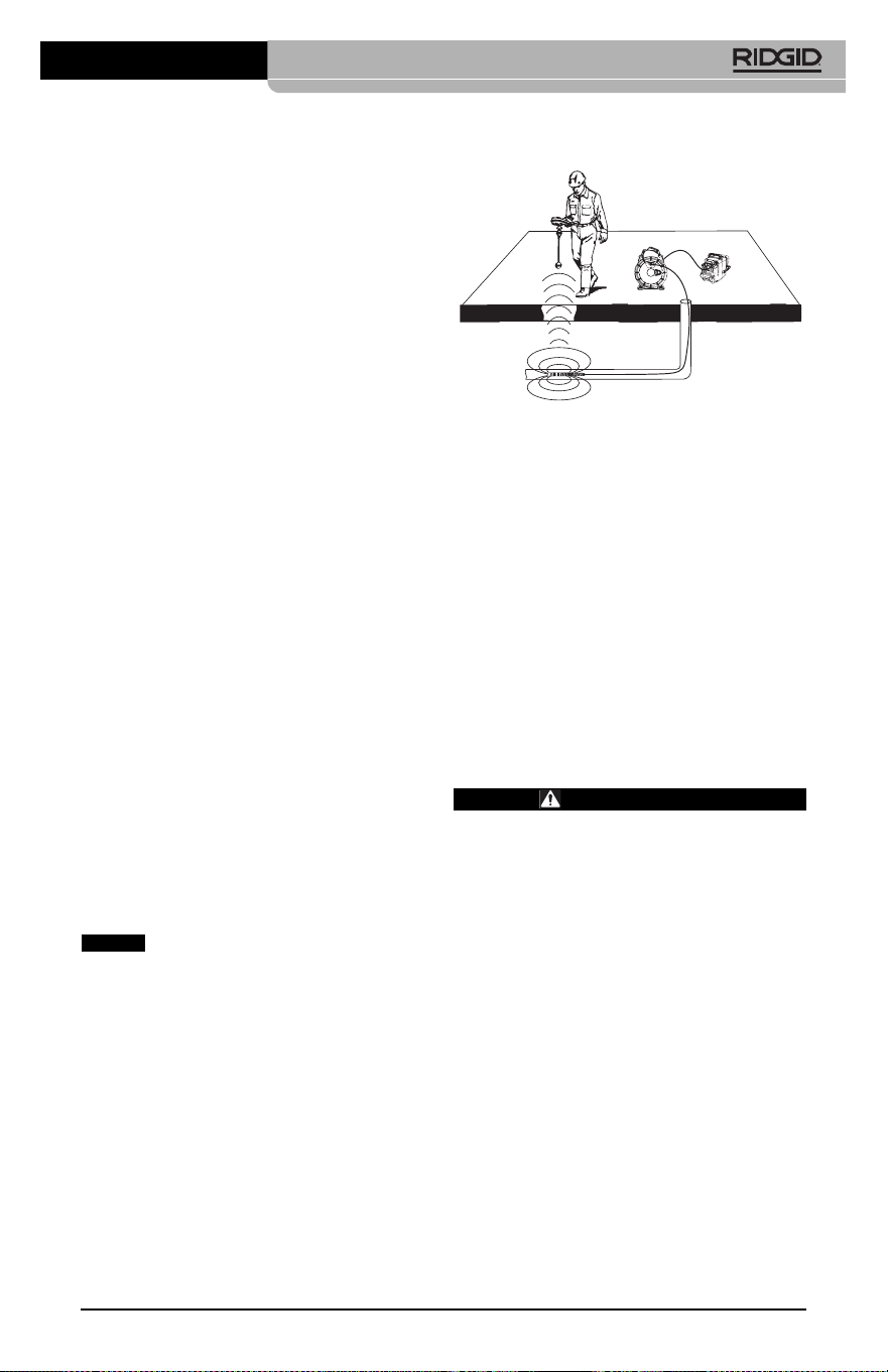
Cámara de inspección micro CA-350
49
pección SeeSnake para visualizar y grabar
solamente.
Cuando se la vaya a utilizar con uno de los
equipos de inspección SeeSnake, deben
sacársele tanto el formador de imágenes y
las extensiones de cable. Si se conecta a un
microReel, microDrain™, nanoReel u otro
equipo similar, consulte el manual del operario
propio de cada uno de estos aparatos para
saber cómo se conectan y usan. Si se co -
necta a otros equipos de inspección SeeSnake
(generalmente un Rollo con Monitor), se re-
quiere un adaptador para conectar la Cámara
de inspección micro CA-350 a un puerto de
salida de video (Video-Out) en el equipo de
ins pección SeeSnake. Conectados de esta
manera, la Cámara de inspección micro CA-
350 mostrará lo que “ve” la cámara y puede uti-
lizarse como grabadora.
Si conecta la Cámara de inspección a un
Rollo de inspección SeeSnakeSeeSnake
(microReel, microDrain™ o nanoReel), alinee
el módulo de interconexión del Rollo con el
conector del cable en la Cámara de inspección
micro CA-350, métalo rectamente y asiéntelo
(Figura 18).
Figura 18 – Conexión entre la micro CA-350 y
un equipo de inspección SeeSnake
No tuerza la conexión para impedir
que se dañen los enchufes.
Localización de la Sonda
Si durante la inspección se hará uso de una
sonda (transmisor que navega por un de-
sagüe), es posible monitorearla de dos mane -
ras: 1) si el Rollo de inspección dispone de un
mando de Sonda, éste activa y desactiva la
Sonda; o 2) la Sonda se activa al reducir la lu-
minosidad de los LED a cero. Una vez local-
izada la Sonda, los LED pueden ponerse de
nuevo a la luminosidad normal y seguir ade-
lante con la ins pección.
Cualquier localizador de RIDGID -como el
SR-20, SR-60, Scout o NaviTrack
®
II-, puestos
a 512 Hz, sirve para efectuar localizaciones
puntuales en el desagüe que se inspecciona.
Figura 19 – Localización de la Sonda de un
Rollo de inspección
Para localizar la Sonda, encienda el locali -
zador y póngalo en modalidad Sonda. Camine
rastreando en la dirección en que probable-
mente se encuentra la Sonda hasta que el
localizador la detecte. Una vez detectada la
Sonda, siga las indicaciones del localizador
para concentrar toda su atención sobre ella y
determinar con exactitud dónde se encuentra.
Para obtener instrucciones detalladas de los
métodos de localización de sondas, consulte el
manual del operario del modelo de localizador
que utilizará.
Mantenimiento
ADVERTENCIA
Antes de limpiar el aparato, extráigale la
batería.
• Después de cada uso, limpie el cabezal
formador de imágenes y el cable con jabón
o detergente suaves.
• Pásele un paño seco y limpio a la pantalla.
No frote la pantalla con el paño.
• Sólo use un bastoncillo de algodón untado
en alcohol para limpiar las conexiones.
• Pásele un paño limpio y seco a todo el
visualizador de mano.
Función de re-alistar
Si el aparato deja de funcionar, oprima el
botón Reset (re-alistar) (ubicado debajo de la
tapa en el costado izquierdo del visualizador,
Figura 4). Debería volver a funcionar normal-
mente después de encenderse.
AVISO
Equipo opcional
ADVERTENCIA
Para reducir el riesgo de lesiones, utilice
exclusivamente los equipos específica-
mente diseñados y recomendados para
usarse con la Cámara de inspección
micro CA-350 de RIDGID tales como los
listados a continuación. Otros equipos
aptos para usarse con otros aparatos
pueden tornarse peligrosos si se utilizan
con la Cámara de inspección micro CA-
350.
Cámara de inspección micro CA-350
50
Para ver una lista completa de equipos RIDGID
disponibles para este aparato, vea el catálogo
de Ridge Tool en línea en RIDGID.com o llame
al Departamento de Servicio Técnico de Ridge
Tool al (800) 519-3456
Almacenamiento
La Cámara de inspección micro CA-350 de
RIDGID debe almacenarse en un lugar seco
y seguro, a temperaturas entre -4°F (–20°C) y
140°F (60°C) y humedad relativa entre un 15
y un 85%.
Guarde el aparato bajo llave fuera del al-
cance de niños y personas no capacitadas
para usar esta Cámara de inspección.
Extraiga la batería del aparato, antes de
guardarlo o enviarlo.
Servicio y reparaciones
ADVERTENCIA
Es peligroso hacer funcionar la Cámara
de inspección micro CA-350 si no se ha
reparado ni se le ha hecho servicio en la
forma debida.
El servicio y reparación de la Cámara de ins-
pección micro CA-350 debe ser efectuado
por un Servicentro Autorizado RIDGID.
Para obtener información acerca del Servi-
centro Autorizado RIDGID más cercano a
su localidad o consultar sobre el servicio o
reparación de este aparato:
• Contacte al distribuidor RIDGID en su locali -
dad.
• Visite RIDGID.com para averiguar dónde
se encuentran los centros autorizados
RIDGID más cercanos.
• Llame al Departamento de Servicio
Técnico de RIDGID desde EE.UU. o
Canadá al (800) 519-3456 o escriba a
rtctechservices@emerson.com .
Eliminación del equipo
Piezas y partes de la Cámara de inspección
CA-350 han sido fabricadas de materiales
valiosos posibles de reciclar. Averigüe cuáles
empresas se especializan en reciclaje en su
localidad. Deseche sus componentes cum -
pliendo con todas y cada una de las disposi-
ciones vigentes en su jurisdicción. Para mayor
información, llame a la agencia local encar-
gada de la eliminación de residuos sólidos.
No. en el
catálogo Descripción
37108 Cable de extensión de 3 pies (90 cm)
37113 Cable de extensión de 6 pies (180 cm)
37103 Formador de imágenes 17 mm y cable
37098 Formador de imágenes 6 mm Ø c/cable
de 1 m.
37093 Formador de imágenes 6 mm. Ø c/cable
de 4 m
37123 Paquete de accesorios (17 mm):
gancho, imán y espejo
36758 Adaptador CA
40623 Auriculares con micrófono
No. en el Tipo de
catálogo Región enchufe
55193 Cargador EE. UU., Canadá y México A
55198 Cargador Europa C
55203 Cargador China A
55208 Cargador Australia y América Latina I
55213 Cargador Japón A
55218 Cargador Reino Unido G
44798 Cable del Norteamérica A
cargador
44808 Cable del Europa C
cargador
44803 Cable del China A
cargador
44813 Cable del Australia y América Latina I
cargador
44818 Cable del Japón A
cargador
44828 Cable del Reino Unido G
cargador
No. en el
catálogo Modelo Capacidad
55183 RB-1225 12V; 2,5 A
Baterías
Todas las baterías listadas funcionarán con cargadores RBC-121
de cualquier número de catálogo.
Cargadores y cordones RBC-121

En la Comunidad Europea: ¡No
se deshaga de equipos eléctricos
junto con la basura doméstica!
Según la directriz de la Comunidad
Europea 2012/19/EU, impartida a
sus países miembros sobre dese-
chos eléctricos y electrónicos, los equipos
eléctricos inutilizables deben ser recolecta-
dos en forma separada de la basura municipal
y eliminados sin causar daños al medio am -
biente.
Cámara de inspección micro CA-350
51

Cámara de inspección micro CA-350
52
SÍNTOMA POSIBLE CAUSA SOLUCIÓN
La pantalla se
enciende pero no
muestra imagen.
Los DELs en el forma -
dor de imágenes per -
manecen tenues aun -
que puestos a intensi-
dad máxima; display
vacila entre blanco y
negro; display en colo -
res se apaga después
de breves instantes.
El aparato no se
enciende.
Detección de averías
Conexiones del cable sueltas.
Formador de imágenes averiado.
Formador de imágenes cubierto de
mugre.
Batería con poca carga.
Batería totalmente descargada.
El aparato necesita re-alistarse.
Revise las conexiones del cable, lím -
pielas si es necesario. Reconéctelas.
Reemplace el formador de imágenes.
Inspeccione el formador de imágenes
para cerciorarse de que no está cu-
bierto de mugre.
Introdúzcale una batería cargada.
Introdúzcale una batería cargada.
Re-aliste el aparato. Consulte la sec-
ción Mantenimiento.

micro CA-350
micro CA-350 Muayene ve Gözlem Kamerası
Aşağıdaki Seri Numarasını kaydedin ve isim levhasındaki ürün seri numarasını muhafaza edin.
Seri
No.
micro CA-350
Muayene ve Gözlem
Kamerası
UYARI
Bu makineyi kullanmadan
önce Kullanıcı Kılavuzunu
dikkatlice okuyun. Bu kıla-
vuzun içeriğinin anlaşılma-
ması ve ona uyulmaması
elektrik çarpması, yangın
ve/veya ağır kişisel yara-
lanmalara yol açabilir.

micro CA-350 Muayene ve Gözlem Kamerası
54
İçindekiler
Güvenlik Sembolleri .......................................................................................................................................................... 55
Genel Güvenlik Bilgileri ................................................................................................................................................... 55
Çalışma Alanı Güvenliği ................................................................................................................................................. 55
Elektrik Güvenliği ............................................................................................................................................................. 55
Kişisel Güvenlik ................................................................................................................................................................. 55
Kullanım ve Bakım ........................................................................................................................................................... 56
Pil Kullanımı ve Bakımı ................................................................................................................................................... 56
Servis ..................................................................................................................................................................................... 56
Özel Güvenlik Bilgileri ...................................................................................................................................................... 56
micro CA‑350 Muayene ve Gözlem Kamerası Güvenliği ................................................................................. 56
Açıklama, Teknik Özellikler ve Standart Ekipman ............................................................................................ 57
Açıklama .............................................................................................................................................................................. 57
Özellikler .............................................................................................................................................................................. 57
Standart Ekipman ............................................................................................................................................................ 58
Kumandalar ........................................................................................................................................................................ 58
FCC Açıklaması ..................................................................................................................................................................... 58
Elektromanyetik Uyumluluk (EMC)........................................................................................................................... 59
Simgeler ................................................................................................................................................................................... 59
Cihazın Montajı .................................................................................................................................................................... 59
Pillerin Değiştirilmesi/Takılması ................................................................................................................................. 59
AC Adaptörüne güç verilmesi .................................................................................................................................... 60
Kamera Kafası Kablosunu veya Uzatma Kablolarını Takma .............................................................................. 60
Aksesuarların Takılması .................................................................................................................................................. 60
SD™ Kartın Takılması ....................................................................................................................................................... 60
Çalışma Öncesi Kontrol .................................................................................................................................................... 61
Aletin ve Çalışma Alanının Hazırlanması ............................................................................................................... 61
Kullanım Talimatları .......................................................................................................................................................... 62
Canlı Ekran .......................................................................................................................................................................... 63
Görüntü Ayarı ................................................................................................................................................................... 63
Görüntü Yakalama ........................................................................................................................................................... 64
Menü ..................................................................................................................................................................................... 64
Zaman Damgası ............................................................................................................................................................... 65
Dil ................................................................................................................................................................................ 65
Tarih/Saat .................................................................................................................................................................. 65
TV‑Çıkışı................................................................................................................................................................................ 65
Donanım Yazılımını Güncelle ...................................................................................................................................... 65
Hoparlör .................................................................................................................................................................... 65
Otomatik Kapatma ................................................................................................................................................. 65
Fabrika Ayarlarına Sıfırlama ................................................................................................................................. 65
Hakkında .............................................................................................................................................................................. 65
Görüntülerin Bir Bilgisayara Aktarılması ................................................................................................................. 65
TV'ye Bağlama ................................................................................................................................................................... 66
SeeSnake
®
Kanal Görüntüleme Ekipmanı ile Kullanım .................................................................................... 66
Bakım ........................................................................................................................................................................................ 67
Sıfırlama Fonksiyonu ...................................................................................................................................................... 67
İsteğe Bağlı Ekipman ........................................................................................................................................................ 67
Saklama.................................................................................................................................................................................... 67
Servis ve Tamir ...................................................................................................................................................................... 68
Elden Çıkarma ....................................................................................................................................................................... 68
Sorun Giderme ..................................................................................................................................................................... 68
Ömür Boyu Garanti
.......................................................................................................................................... Arka Kapak
* Orijinal kılavuzun çevirisidir
micro CA-350 Muayene ve Gözlem Kamerası
55
Güvenlik Sembolleri
Bu kullanıcı kılavuzunda ve ürün üzerinde güvenlik sembolleri ve uyarı kelimeleri önemli gü‑
venlik bilgilerini bildirmek için kullanılmıştır. Bu kısım, bu uyarı kelimelerinin ve sembollerin
daha iyi anlaşılması için sunulmuştur.
Bu güvenlik uyarı sembolüdür. Sizi potansiyel kişisel yaralanma tehlikesine karşı uyarmak
için kullanılır. Muhtemel yaralanma veya ölümden sakınmak için bu sembolü izleyen tüm
güvenlik mesajlarına uyun.
TEHLİKE
UYARI
DİKKAT
BİLDİRİM
TEHLİKE sakınılmadığı takdirde ölüm veya ciddi yaralanmayla sonuçlanacak tehli‑
keli bir durumu gösterir.
UYARI sakınılmadığı takdirde ölüm veya ciddi yaralanmayla sonuçlanabilecek tehli‑
keli bir durumu gösterir.
DİKKAT sakınılmadığı takdirde küçük veya orta derece yaralanmaya yol açabilecek
tehlikeli bir durumu gösterir.
BİLDİRİM eşyanın korunmasıyla ilgili bilgileri gösterir.
Bu sembol ekipmanı kullanmadan önce kullanıcı kılavuzunun dikkatlice okunması ge‑
rektiği anlamına gelir. Kullanıcı kılavuzu ekipmanın güvenli ve düzgün kullanımına dair
önemli bilgiler içerir.
Bu sembol göz yaralanması riskini azaltmak için ekipmanı taşırken veya kullanırken dai‑
ma yan korumaları olan güvenlik gözlükleri veya koruyucu gözlüklerin takılması gerek‑
tiğini gösterir.
Bu sembol el, parmak veya bedenin diğer kısımlarının donanım veya diğer hareketli par‑
çalara kaptırılması veya sıkışması riskini gösterir.
Bu sembol elektrik çarpması riskini gösterir.
Genel Güvenlik Bilgileri
UYARI
Tüm güvenlik uyarılarını ve talimatları okuyun.
Uyarı ve talimatlara tam olarak uyulmaması
elektrik çarpması, yangın ve ağır yaralanmala‑
ra yol açabilir.
BU TALİMATLARI SAKLAYIN!
Çalışma Alanı Güvenliği
• Çalışma alanının temiz ve iyi aydın-
latılmış olmasını sağlayın. Dağınık ve
karanlık alanlar kazalara yol açabilir.
• Ekipmanı alev alabilen sıvıların, gazla-
rın ya da tozların olduğu patlayıcı or-
tamlarda kullanmayın. Ekipman toz ya
da gazları tutuşturabilecek kıvılcımlar
üretebilir.
• Ekipmanı kullanırken çocukları ve izle-
yenleri uzakta tutun. Dikkatinizi dağıtan
şeyler kontrolü kaybetmenize sebep ola‑
bilir.
Elektrik Güvenliği
• Borular, radyatörler, ocaklar ve buz-
dolapları gibi topraklanmış yüzeylerle
vücut temasından kaçının. Eğer vücu‑
dunuz topraklanmışsa elektrik çarpması
ihtimali artar.
• Ekipmanı yağmura ya da ıslak koşul-
lara maruz bırakmayın. Ekipmana gi‑
ren su, elektrik çarpması ihtimalini artırır.
Kişisel Güvenlik
• Dikkatli olun, ne yaptığınıza dikkat edin
ve ekipmanı kullanırken sağduyunu-
zu kullanın. Yorgunken ya da ilaçların,
alkol veya tedavi etkisindeyken ekip-
manı kullanmayın. Ekipmanın kullanımı
esnasında bir anlık dikkatsizlik önemli
kişisel yaralanmalara yol açabilir.
• Aşırı zorlamadan kullanın. Her seferin-
de uygun düzeyde ve dengede kulla-
nın. Bu, beklenmedik durumlarda elekt‑
rikli aleti daha iyi kontrol etmenizi sağlar.
• Kişisel koruyucu ekipmanlar kullanın.
Daima koruyucu gözlük takın. Toz mas‑
keleri, kaymaz güvenlik ayakkabıları, sert
şapkalar ve kulak korumaları gibi koru‑

micro CA-350 Muayene ve Gözlem Kamerası
56
yucu ekipmanların kullanımı kişisel yara‑
lanmaların azalmasını sağlar.
Kullanım ve Bakım
• Ekipmanı zorlamayın. Yapacağınız işe
uygun ekipman kullanın. Doğru ekip‑
man işinizi, uygun tasarlandığı oranda
daha iyi ve güvenli şekilde yapar.
• Anahtar ekipmanı AÇIP KAPATMIYOR-
SA ekipmanı kullanmayın. Anahtar ile
kontrol edilemeyen aletler tehlikelidir ve
tamir edilmelidir.
• Tüm ayarlamaları, aksesuar değişimini
gerçekleştirmeden veya saklamadan
önce pilleri cihazdan çıkarın. Bu güven‑
lik önlemleri yaralanma riskini azaltır.
• Kullanmadığınız ekipmanı çocukların
erişemeyeceği yerlerde saklayın ve
ekipmanı kullanma deneyimi olma-
yan ya da bu talimatlardan habersiz
kişilerin ekipmanı kullanmalarına izin
vermeyin. Ekipman, eğitimsiz kullanıcı‑
ların ellerinde tehlikeli olabilir.
• Ekipmanın bakımını yapın. Ekipma‑
nın çalışmasını olumsuz etkileyebilecek
eksik veya kırık parçaları ve diğer durum‑
ları kontrol edin. Eğer hasarlıysa, ekipma‑
nı kullanmadan önce tamir ettirin. Birçok
kaza bakımsız ekipmandan kaynaklanır.
• Ekipmanı ve aksesuarlarını çalışma
koşullarını ve yapılacak işi göz önün-
de bulundurarak bu talimatlara uy-
gun şekilde kullanın. Ekipmanın tasar‑
landığı uygulama dışında kullanılması
tehlikeli durumlara sebep olabilir.
• Sadece, üretici tarafından ekipma-
nınız için tavsiye edilen aksesuarları
kullanın. Bir ekipman için uygun olan
aksesuarlar başka bir ekipmanda kulla‑
nıldığında tehlikeli olabilir.
• Tutma yerlerini kuru ve temiz tutun;
yağ ve gresten arındırın. Bu, ekipmanı
daha iyi kavramanızı sağlar.
Pil Kullanımı ve Bakımı
• Yalnızca üretici tarafından belirlenmiş
şarj aleti ile şarj edin. Bir pil takımı tü‑
rüne uygun olan şarj aletinin başka bir
pil takımı türünü şarj etmek için kulla‑
nılması yangına sebep olabilir.
•
Ekipmanı, sadece özel olarak belirlen-
miş pillerle kullanın. Başka pillerin kulla‑
nımı yaralanma ve yangına sebep olabilir.
• Pilleri kullanmadığınızda ataç, bozuk
para, anahtar, çivi, vida, küçük parça-
lar gibi bir kutuptan diğerine bağlantı
yapabilecek metal cisimlerden uzak
tutun. Pil kutuplarını birbirine değdir‑
mek yanık ve yangınlara sebep olabilir.
• Kötü kullanım koşullarında pilden sıvı
çıkabilir, bu sıvıya temas etmekten ka-
çının. Kazayla temas ederseniz su ile yı‑
kayın. Eğer sıvı gözünüze temas eder‑
se, tıbbi yardım da alın. Pilden çıkan
sıvı kaşıntı ve yanıklara sebep olabilir.
Servis
• Ekipmanınızın onarımını yetkili uz-
man kişilere sadece orijinal yedek
parçaları kullanarak yaptırın. Bu, aletin
güvenliğinin devamlılığını sağlayacaktır.
Özel Güvenlik Bilgileri
UYARI
Bu kısım muayene kamerasına özel önemli
güvenlik bilgisi içerir.
Elektrik çarpması veya diğer ciddi yaralanma
risklerini azaltmak için RIDGID® micro CA‑350
Muayene ve Gözlem Kamerası'nı kullanma‑
dan önce bu önlemleri dikkatlice okuyun.
BU TALİMATLARI SAKLAYIN!
Bu kılavuzu kullanıcının kullanımı amacıyla alet‑
le birlikte muhafaza etmek için micro CA‑350
Muayene ve Gözlem Kamerası'nın taşıma çanta‑
sında bir kılavuz koyma yeri temin edilmiştir.
micro CA‑350 Muayene ve Gözlem
Kamerası Güvenliği
• Görüntüleme ünitesini suya veya yağ-
mura maruz bırakmayın. Bu durum
elektrik çarpması riskini artırır. micro
CA‑350 kamera kafası ve kablosu 10’ (3m)
derinliğe kadar su geçirmezdir. El tipi gö‑
rüntüleme ünitesi değildir.
• micro CA-350 Muayene ve Gözlem
Kamerası'nı elektrik akımı olabilecek
yerlere koymayın. Bu durum elektrik
çarpması riskini artırır.
• micro CA-350 Muayene ve Gözlem
Kamerası'nı hareketli parçalar bulu-
nabilecek yerlere koymayın. Bu durum
karmaşık yaralanmalara yol açabilir.
• Bu cihazı, kişisel muayene için ya da
tıbbi amaçlı kullanmayın. Bu medikal
bir cihaz değildir. Bu durum kişisel ya‑
ralanmaya yol açabilir.
• micro CA-350 Muayene ve Gözlem
Kamerası'nı tutarken veya kullanır-

micro CA-350 Muayene ve Gözlem Kamerası
57
ken her zaman uygun kişisel koru-
yucu ekipmanlar kullanın. Su yolları
ve zehirli, bulaşıcı olabilecek kimyasal,
bakteri ve diğer maddeleri içerebilecek
diğer alanlar, yanıklara veya diğer sorun‑
lar yol açanilirler. Uygun kişisel koru-
yucu ekipmanlar her zaman güven-
lik gözlükleri ve eldivenleri içerir
ve lateks veya lastik eldivenler yüz koru‑
yucular, koruyucu gözlükler, koruyucu
elbiseler, solunum cihazları ve çelik uçlu
ayakkabılar içerebilir.
• İyi hijyen koşullarını sağlayın. Kimyasal ve
bakteri içerebilen su yolları ve diğer alanla‑
rı muayene etmek için micro CA‑350 Mu‑
ayene ve Gözlem Kamerası'nı tuttuktan
veya kullandıktan sonra elleri ve bedenin
su yolu içeriğine maruz kalmış diğer kı‑
sımlarını yıkamak için sıcak ve sabunlu su
kullanın. micro CA‑350 Muayene ve Göz‑
lem Kamerası'nı kullanırken veya çalıştırır‑
ken yiyip içmeyin. Bu sayede zehirli veya
bulaşıcı malzemelerle bulaşmanın önüne
geçilir.
• Kullanıcı veya cihaz suda dururken
micro CA-350 Muayene ve Gözlem
Kamerası'nı kullanmayın. Sudayken
elektrikli bir cihazın kullanılması elekt‑
rik çarpması riskini artırır.
Gerektiğinde, AT uyumluluk beyanı (890‑011‑
320.10) ayrı bir kitapçık olarak, bu kılavuzun
yanında yer alır.
Bu RIDGID® ürünü ile ilgili sorularınız için:
– Bulunduğunuz bölgedeki RIDGID bayisi
ile iletişim kurun.
– Yerel RIDGID irtibat noktasının iletişim bil‑
gilerine erişmek için RIDGID.com adresini
ziyaret edin.
– RIDGID Teknik Servis Departmanı ile iletişim
kurmak için r[email protected]
adresine yazın veya ABD ve Kanada'da
(800) 519‑3456 numaralı telefonu arayın.
Açıklama, Teknik
Özellikler ve Standart
Ekipman
Açıklama
RIDGID micro CA‑350 Muayene ve Gözlem Ka‑
merası elle kullanılan güçlü bir dijital kayıt cihazı‑
dır. Tamamen dijital olan bu platform ulaşılması
zor alanlarda muayene ve gözlemlerinizi gerçek‑
leştirmenizi ve resim ve videolarını kaydetmenizi
sağlar. Ayrıntılı ve doğru görsel muayeneleri ger‑
Önerilen Kullanım..... İç mekan
Görülebilir Mesafe.... 0.4" (10 mm) ila ∞
Ekran.............................. 3.5” (90 mm) Renkli
LCD (320 x 240
Çözünürlük)
Kamera Kafası.............
3
/
4
" (17 mm)
Aydınlatma.................. 4 Adet Ayarlanabilir
LED
Kablonun
Ulaşabileceği
Uzaklık...........................
3' (90 cm), uzatılabilir,
İsteğe Bağlı
Uzatmalarla 30' (9m)
kadar uzatılabilir,
Kamera Kafası ve
Kablo 10' (3m) Su
geçirmezdir, IP67
Fotoğraf Biçimi........... JPEG
Görüntü
Çözünürlüğü...............
640 x 480
Video Biçimi................. MP4
Video
Çözünürlüğü...............
640 x 480
Çerçeve Hızı................. 30 FPS Kadar
TV‑Çıkışı....................... PAL/NTSC
Kullanıcı tarafından
seçilebilir
Dahili Bellek............... 235 MB Bellek
Harici Bellek............... SD™ Kartı 32 GB maks.
(8 GB sağlanır)
Veri Çıkışı..................... USB Veri Kablosu ve
SD™ Kart
Çalışma Sıcaklığı...... 32°F ile 113°F arası
(0°C ile 45°C arası)
Saklama Sıcaklığı..... ‑4°F ile 140°F arası
(‑20°C ile 60°C arası)
Güç Kaynağı............... 12V Li‑Ion Pil AC
Adaptörü 12V, 3 Amp
Ağırlık........................... 5.5 lbs (2,5 kg)
çekleştirmeniz için sisteme görüntü döndürme
ve dijital zum gibi çeşitli görsel işleme özellikleri
yerleştirilmiştir. Alet harici bir belleğe ve TV‑Çıkışı
özelliğine sahiptir. Uygulama esnekliği için ka‑
mera kafasına eklenmek üzere (kanca, mıknatıs
ve ayna) aksesuarlar dahil edilmiştir.
Özellikler

micro CA-350 Muayene ve Gözlem Kamerası
58
Standart Ekipman
micro CA‑350 Muayene ve Gözlem Kamerası
aşağıdakilerle birlikte verilir:
• micro CA‑350 El takımı
• 17 mm Kamera kafası
• 3’ (90 cm) USB Kablosu
• 3’ (90 cm) Sesli RCA Kablosu
• Kanca, Mıknatıs, Ayna Aksesuarları
• 12V Li‑Ion Pil
• Kablolu Li‑Ion Pil Şarj Cihazı
• AC Adaptörü
• Mikrofonlu Kulaklık Aksesuarı
• 8 GB SD™ Kartı
• Kullanma Kılavuzu
Şekil 1 - micro CA-350 Muayene ve Gözleme
Kamerası
Kumandalar
Açma/
Kapama
(Güç)
Menü
Seç/Onayla
Geri
Deklanşör
Şekil 2 - Kumandalar
Görüntüyü
Döndür
Oklar
Şekil 3 - Sağ Yan Bağlantı Noktası Kapağı
Entegre
Mikrofon
Kulaklık
Jakı
Hoparlör
AC
Adaptörü
Şekil 4 - Sol Yan Bağlantı Noktası Kapağı
Sıfırlama Düğmesi
TV-
Çıkışı
Mini-B USB
SD™ Yuvası
FCC Açıklaması
Bu cihaz test edilmiş ve FCC Kurallarının 15. bö‑
lümü çerçevesinde B Sınıfı dijital cihaz limitleri‑
ne uygun bulunmuştur Bu limitler bir yerleşim
alanında zararlı parazitlere karşı makul bir koru‑
ma sağlamak üzere tasarlanmışlardır.
Bu cihaz, radyo frekans enerjisi üretir, kullanır ve
yayabilir, eğer talimatlara uygun olarak kurulup
kullanılmaz ise telsiz iletişimlerde zararlı parazit‑
lere neden olabilir.
Bununla birlikte belli bir kurulum sonrasında
parazitlenmenin ortaya çıkmayacağına dair bir
garanti yoktur.
Eğer bu cihaz, radyo ve televizyonun ses/
görüntü alımında cihazı AÇIK ve KAPALI hale
getirerek tespit edilebilen zararlı parazitlenme‑
lere neden olursa kullanıcının parazitlenmeleri
düzeltebilmek için aşağıdaki önlemlerden bir
veya daha fazlasını denemesi önerilir:
• Alıcı anteni tekrar yönlendirin ya da yerleş‑
tirin.
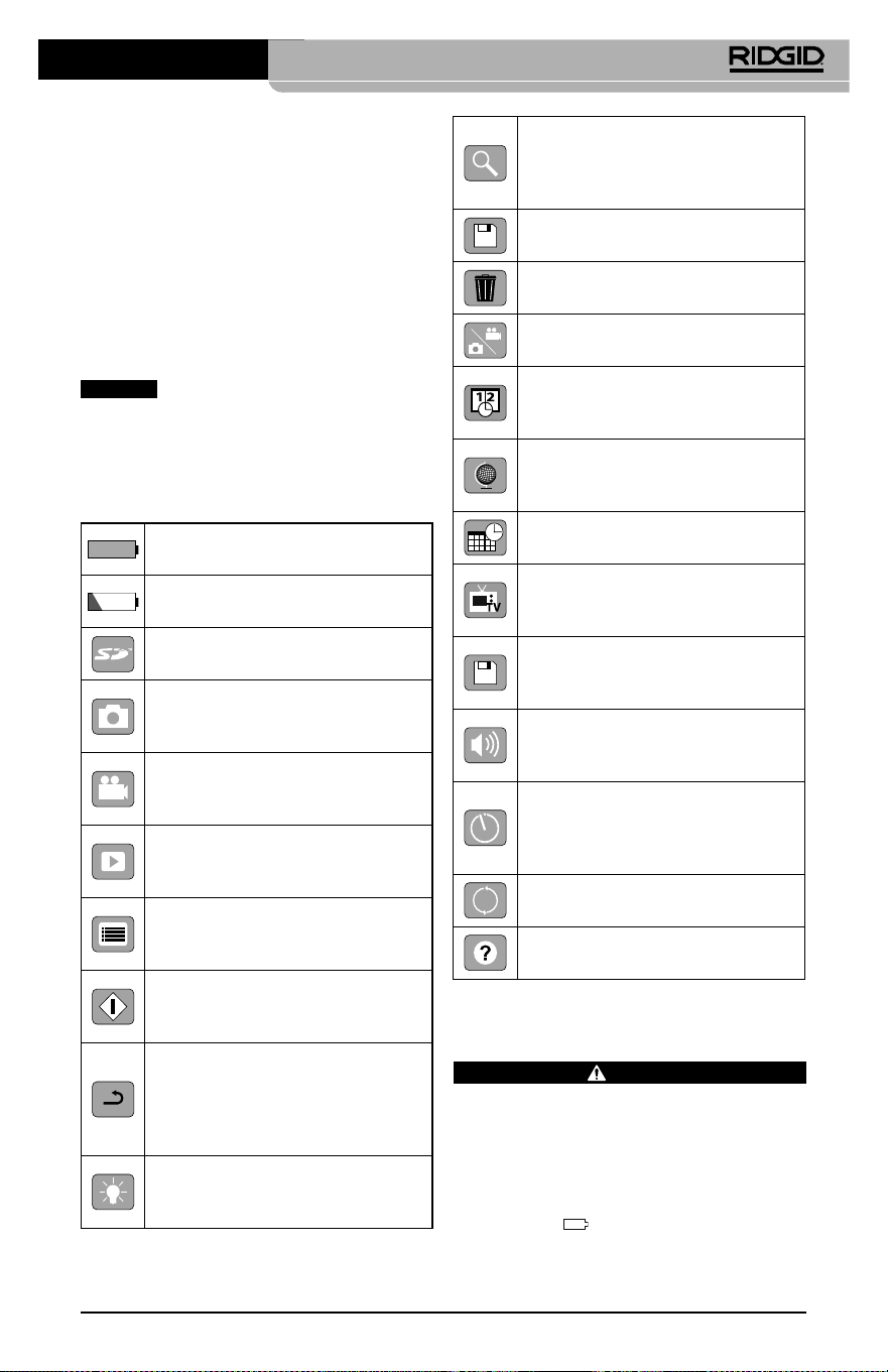
micro CA-350 Muayene ve Gözlem Kamerası
59
Cihazın Montajı
UYARI
Kullanım esnasında ciddi yaralanma riskini
azaltmak amacıyla doğru montaj için aşağı‑
daki prosedürleri izleyin.
Pillerin Değiştirilmesi/Takılması
micro CA‑350 üzerinde piller takılı olarak gelir.
Pil göstergesi
gösteriyorsa, pilin şarj edil‑
mesi gerekir. Depolamadan önce pili çıkartın.
• Cihaz ve alıcı arasındaki mesafeyi arttırın.
• Yardım için satıcıya ya da tecrübeli bir rad‑
yo/TV teknisyenine danışın.
Elektromanyetik
Uyumluluk (EMC)
Elektromanyetik uyumluluk terimi, elektro‑
manyetik yayılma ve elektrostatik boşalmaların
bulunduğu ortamlarda ve diğer ekipmanlarda
elektromanyetik parazite neden olmadan ürü‑
nün, sorunsuz olarak çalışması anlamına gelir.
BİLDİRİM
RIDGID micro CA‑350 Muayene ve
Gözlem Kamerası tüm geçerli EMC standartları‑
na uyumludur. Ancak diğer cihazlarda parazite
neden olma ihtimali önlenemez.
Simgeler
Pil Ömrü Göstergesi – Tam şarjlı
pil.
Pil Ömrü Göstergesi – Pil şarjı
%25'ten az.
SD™ Kart – Cihaza SD Kartı yerleşti‑
rildiğini gösterir.
Fotoğraf Modu – Cihazın çalıştır‑
ma fotoğraf makinesi modunda
çalıştığını gösterir.
Video Kamera Modu – Cihazın
video kamera modunda çalıştığını
gösterir.
İzleme Modu – Bu simgeyi seçmek
önceden kaydedilmiş görselleri ve
videoları izleyip silmenizi sağlar.
Menü – Bu simge üzerindeyken
seç'e basarak ikincil ayar ekranına
geçebilirsiniz.
Seç – Canlı ekrandayken seç düğ‑
mesine basmak sizi izleme ekranına
götürür.
Geri – Canlı ekrandayken geri düğ‑
mesine basmak kamera ve video
arasında geçiş yapılmasını sağlar.
Geri aynı zamanda menüden ve
izleme modundan da çıkaracaktır.
LED Parlaklığı – LED parlaklığını
değiştirmek için sol ve sağ oklara
basın.
Yaklaşma – Görüntüye yaklaşma
oranını 1.0x ila 2.0x arasında değiş‑
tirmek için yukarı ve aşağı oklara
basın.
Kaydet – Resim veya videonun
hafızaya kaydedildiğini gösterir.
Çöp Kutusu – Silme onay simgesi.
Mod – Resim, video veya izleme
modu arasında seçim yapar.
Zaman Göstergesi – Canlı ekran‑
da tarih ve saati göstermek veya
gizlemek için seçin.
Dil – İngilizce, Fransızca, İspanyolca,
Almanca, Felemenkçe, İtalyanca vs
arasında seçim yapın.
Saat ve Tarih – Saat ve tarihi ayarla‑
mak için bu ekrana girin.
TV – TV çıkışı video biçimini etkin‑
leştirmek için NTSC ve PAL arasında
seçim yapın.
Donanım Yazılımı – Üniteyi en
yeni yazılımla güncellemek için
kullanın.
Hoparlör/Mikrofon – Kayıt ve
oynatma sırasında hoparlörü ve
mikrofonu AÇIP KAPATIR.
Otomatik Kapanma – Herhangi
bir eylemde bulunulmaması halin‑
de cihaz 5, 15 veya 60 dakika sonra
otomatik olarak kapanacaktır.
Fabrika Ayarlarına Sıfırlama –
Fabrika ayarlarına sıfırlar.
Hakkında – Yazılım sürümünü
görüntüler.

micro CA-350 Muayene ve Gözlem Kamerası
60
1. Pil tırnaklarını sıkın (Bkz. Şekil 5) ve pili çı‑
kartmak için çekin.
Şekil 5- Pilin Çıkartılması/Takılması
2. Pilin temas ucunu muayene ve gözlem ale‑
tine Şekil 5 üzerinde gösterildiği gibi yerleş‑
tirin.
AC Adaptörüne güç verilmesi
micro CA‑350 Muayene ve Gözlem Kamerası
AC Adaptörü ile de çalıştırılabilir.
1. Sağ yan bağlantı noktası kapağını açın
(Şekil 3).
2. Kuru elle, AC adaptörünü prize takın.
3. AC adaptörü fişini “DC 12V” işaretli bağ‑
lantı noktasına takın.
Şekil 6 - Üniteye AC Adaptörü İle Güç Verme
Kamera Kafası Kablosunu veya
Uzatma Kablolarını Takma
micro CA‑350 Muayene ve Gözlem Kamerası'nı
kullanmak için, kamera kafası kablosu el ter‑
minaline bağlanmalıdır. Kabloyu el ekran ter‑
minaline bağlamak için soketin ve yuvanın
(Şekil7) doğru hizalanması gerekir. Bunlar hiza‑
landıktan sonra bağlantıyı yerinde tutmak için
tırtıklı düğmeyi elinizle sıkın.
Şekil 7 - Kablo Bağlantıları
Kablonuzu 30 feet (9 metre) kadar uzatabilme‑
niz için 3’ (90 cm) ve 6’ (180 cm) uzunluğundaki
uzatma kabloları kullanılabilir. Uzatmayı ek‑
lemek için ilk önce tırtıklı düğmeyi gevşete‑
rek kamera kafa kablosunu ekran biriminden
çıkartın. Yukarıda (Şekil 7) açıklandığı üzere
uzatmayı el terminaline bağlayın. Kamera kafa
kablosunun kamalı ucunu uzatmanın yuvalı
ucuna bağlayın ve bağlantıyı yerinde tutmak
için tırtıklı düğmeyi parmağınızla sıkın.
Aksesuarların Takılması
Dahil olan üç aksesuar (Kanca, Mıknatıs,
Ayna) kamera kafasına aynı şekilde takılmak‑
tadır.
Şekil 8 - Bir Aksesuarın Takılması
Aksesuar
¼ Tur
Düzlükler
Bağlamak için, kamera kafasını Şekil 8 üzerinde
gösterildiği gibi tutun. Aksesuarın yarım daire
ucunu kamera kafasının içerisine kaydırın. Ardın‑
dan tespit etmek için aksesuarı 1/4 döndürün.
SD™ Kartın Takılması
SD kartı yuvasına erişmek için sol yan bağ‑
lantı noktası kapağını (Şekil 4) açın. SD kar‑
tını, köşenin yanındaki simgeyle eşleştirerek
köşeli açılı yuvaya takın (Şekil 9) SD kartı
yuvasına yerleştirin. SD kartları sadece tek
yönde takılabilir, zorlamayın. Bir SD Kart yer‑
leştirildiğinde ekranın üst sol kısmında SD
Kartta saklanabilecek görüntü sayısı veya vi‑
deo uzunluğu ile beraber bir küçük SD kartı
simgesi belirir.
micro CA-350 Muayene ve Gözlem Kamerası
61
Şekil 9 - SD Kartın Takılması
Çalışma Öncesi Kontrol
UYARI
Her kullanımdan önce elektrik çarpması ve
diğer sebeplerden kaynaklanabilecek ciddi
yaralanma riskini azaltmak ve aletin zarar gör‑
mesini önlemek için Muayene ve Gözlem Ka‑
meranızı inceleyin ve her türlü sorunu giderin.
1. Cihazın kapalı olduğundan emin olun.
2. Pili çıkartın ve hasar görüp görmediğini
kontrol edin. Gerekirse pilleri değiştirin. Pil‑
ler hasarlıysa, Muayene ve Gözlem kamera‑
sını kullanmayın.
3. Ekipmanın üzerindeki tüm yağı, gres yağını
veya tozu temizleyin. İncelemede ve aletin
elinizden kaymasını önlemede yardımcı
olur.
4. micro CA‑350 Muayene ve Gözlem
Kamerası'nı kırık, aşınmış, eksik, yanlış yer‑
leştirilmiş veya yanlış bağlanmış parçalar ve
normal, güvenli kullanımı engelleyebilecek
durumlar açısından kontrol edin.
5. Kameranın kafa lensinde yoğunlaşma ol‑
madığını kontrol edin. Lensin içinde yoğun‑
laşma olmuşsa alete zarar vermemek için
kamerayı kullanmayın. Kullanmadan önce
suyun buharlaşmasını bekleyin.
6. Tüm kabloyu kırık ve hasara karşı kontrol
edin. Hasar görmüş kablo aletin içine su gir‑
mesine yol açar ve elektrik çarpması riskini
artırır.
7. El terminali, uzatma kabloları ve kamera
kabloları arasındaki bağlantıların sıkılığını
kontrol edin. Kablonun tüm bağlantıları
su geçirmezliği sağlamak için düzgünce
yapılmış olmalıdır. Aletin düzgünce mon‑
te edildiğinden emin olun.
8. Uyarı etiketlerin varlığını, sağlam iliştiril‑
diğini ve okunur olduğunu kontrol edin
(Şekil 10).
Şekil 10 - Uyarı Etiketi
9. İnceleme sırasında herhangi bir sorun tespit
edildiği takdirde, muayene kamerası gerek‑
tiği gibi tamir edilene kadar kullanmayın.
10. Kuru elle pili tekrar takın.
11. Güç Düğmesi'ne basın ve bir saniye ba‑
sılı tutun. Kamera kafası ışıkları yanar ve
ardından bir açılış ekranı görünür. Kame‑
ra hazır olduğunda, kameranın gördüğü
canlı görüntü ekranda gösterilir. Herhan‑
gi bir sorun varsa bu kılavuzun Sorun gi-
derme kısmına müracaat edin.
12. Aleti KAPALI duruma getirmek için Güç
Düğmesi'ne basın ve bir saniye boyunca
basılı Tutun.
Aletin ve Çalışma Alanının
Hazırlanması
UYARI
Elektrik çarpması, dolaşma ve diğer sebep‑
lerden kaynaklanabilecek yaralanma riskini
azaltmak, cihazı ve sistemin hasar görmesini
önlemek için micro CA‑350 Muayene ve Gözlem
Kamerası'nı ve çalışma alanını bu prosedürlere
göre hazırlayın.
micro CA-350 Muayene ve Gözlem Kamerası
62
1. Çalışma alanını aşağıdakiler açısından kont‑
rol edin:
• Yeterli ışıklandırma
• Yanabilir sıvılar, alev alabilir buhar veya
tozlar. Alanda böyle bir kaynak olması du‑
rumunda tanımlayıp düzeltene kadar ça‑
lışma yapmayın. micro CA‑350 Muayene
ve Gözlem Kamerası patlamaya karşı koru‑
malı değildir ve kıvılcımlara neden olabilir.
• Operatör için açık, düz, sağlam, kuru yer.
Suda dururken muayene kamerasını kul‑
lanmayın.
2. Muayene ve Gözlem edeceğiniz alan veya
boşluğu inceleyin ve micro CA‑350 Mua‑
yene ve Gözlem Kamerası'nın iş için uygun
ekipman olup olmadığını belirleyin.
• Boşluğa erişme noktalarını belirleyin.
17mm'lik kamera kafasının içinden geçe‑
bileceği asgari açıklığın çapı yaklaşık
3
/
4
”
(19mm) boyutundadır.
• Muayene edilecek alana uzaklığı belirle‑
yin. En fazla 30’ (9 m) mesafeye uzanmak
için kameraya uzatmalar eklenebilir.
• Kablo içinde çok keskin dönüşler gerekti‑
recek herhangi bir engel olup olmadığını
belirleyin. Muayene kamerası kablosu za‑
rar görmeden 5” (13 cm) yarıçapına kadar
küçülebilir.
• Muayene edilecek alanda elektrik kaynağı
olup olmadığını kontrol edin. Eğer varsa
elektrik çarpması riskini azaltmak için bu
alandaki güç KAPATILMALIDIR. Muayene
esnasında gücün geri açılmasını önlemek
için uygun prosedürleri kullanın.
• Muayene esnasında herhangi bir sıvı ile
karşılaşılıp karşılaşılmayacağını belirleyin.
Kablo ve kamera kafası 10’ (3 m) derinliğe
kadar suya geçirmezdir. Daha derin yerler
kablo ve görüntüleyiciye sıvı girişine ve
dolayısıyla elektrik çarpmasına veya ale‑
tin zarar görmesine yol açabilir. Elle kulla‑
nılan ekran ünitesi su geçirmezdir (IP54)
fakat suya batırılmamalıdır.
• Özellikle su yollarında herhangi bir kim‑
yasal olup olmadığını belirleyin. Herhangi
bir kimyasalın olduğu yerlerde çalışmak
için gerekli olan özel güvenlik tedbirlerini
kavramak önemlidir. Gerekli bilgiler için
kimyasalın imalatçısıyla irtibata geçin.
Kimyasallar muayene kamerasına zarar
verebilir veya aşınmaya uğratabilir.
• Alanın ve alandaki eşyaların sıcaklığını be‑
lirleyin. Teknik Özelliklere bakın. Bu aralığın
dışında kalan alanlarda kullanmak veya
daha sıcak ya da soğuk cisimlere temas
ettirmek kamerada hasara neden olabilir.
• Muayene edilecek alanda herhangi bir ha‑
reketli parça olup olmadığını kontrol edin.
Eğer böyle parçalar varsa dolaşma riskini
azaltmak amacıyla muayene esnasında
bu parçaların hareketi engellenmelidir.
Muayene esnasında parçaların hareketini
önlemek için uygun kilitleme prosedürleri
kullanılmalıdır.
micro CA‑350 Muayene ve Gözlem Kamerası iş
için uygun ekipman değilse, RIDGID'den başka
muayene ve gözlem cihazları da temin edebi‑
leceğinizi unutmayın. RIDGID ürünlerinin tam
listesi için RIDGID.com adresinden RIDGID kata‑
loguna bakın.
3. micro CA‑350 Muayene ve Gözlem
Kamerası'nın her kullanımdan önce
düzgün şekilde kontrol edildiğinden
emin olun.
4. Yapacağınız işe uygun aksesuarlar seçin.
Kullanım Talimatları
UYARI
Kir ve diğer yabancı maddelere karşı gözü‑
nüzü korumak için her zaman göz koruyu‑
cular takın.
Elektrik çarpması, dolaşma ve diğer sebep‑
lerden kaynaklanabilecek yaralanma ris‑
kini azaltmak için çalıştırma talimatlarına
uyun.
1. Muayene ve Gözlem kamerasının ve çalış‑
ma alanının düzgünce hazırlandığından ve
çalışma alanında izleyiciler ve diğer dikkat
dağıtıcıların olmadığından emin olun.
2. Güç Düğmesi'ne basın ve iki saniye bo‑
yunca Basılı tutun. Kamera kafası ışıkları
YANAR ve ardından bir açılış ekranı gö‑
rünür. Bu ekran cihazın işletim sistemin
yüklendiğini gösterir. Ürünün gücü ta‑
mamen açıldığında ekran otomatik ola‑
rak canlı ekrana geçer.

micro CA-350 Muayene ve Gözlem Kamerası
63
Şekil 11 - Açılış Ekranı
(Not: Her donanım yazılımı gün‑
cellemesinde sürüm değişecektir.)
Canlı Ekran
Canlı ekran işinizin çoğu kısmını yapacağınız
yerdir. Kameranın gördüğü canlı görüntü ek‑
randa gösterilir. Bu ekranda zum (yaklaştırma)
yapabilir, LED parlaklığını ayarlayabilir ve resim
ve video görüntüsü alabilirsiniz.
Ekran üst kısmında araç modu, yaklaşma, ta‑
kılıysa SD™ kartı simgesi, kullanılabilir bellek
ve hoparlör/mikrofon AÇIK/KAPALI durumla‑
rını gösteren bir durum çubuğuna sahiptir.
Alt çubuk göstergesinde AÇIKSA tarih ve saat
bilgisini gösterir.
Şekil 12 - Canlı Ekran
Bilgi Çubuğu
Durum Çubuğu
Muayene ve Gözlem Kamerası AÇILDIĞINDA,
varsayılan mod hareketsiz görüntüleri yakala‑
mak içindir.
Menüye herhangi bir zamanda menü düğ‑
mesine basarak erişebilirsiniz. Menü CANLI
Ekranı kaplayacaktır. MOD kategorileri ara‑
sında geçiş yapmak için sağ ve sol ok
tuşlarını kullanın. Menü öğeleri arasında ge‑
zinmek için üst ve alt okları
kullanın ve
istediğiniz zaman seç düğmesine
basın.
Şekil 13 - Ekran Kapatma Modu Seçimi
3.Başka bir muayene ve gözlem kamera‑
sı ayarları (Zaman Göstegesi, Dil, Tarih/
Saat, TV Çıkışı, Ürün Donanımı Güncel‑
leme, Hoparlör/Mikrofon ‑ telefon, Oto‑
matik KAPATMA, Fabrika Ayarlarına Sıfır‑
lama) ile ayarlanması gerekiyorsa, Menü
Bölümü'ne bakın.
4. Kamerayı gözlem için hazırlayın. Kamera
kablosunun alanı gözlemlemesi için ön‑
ceden şekillendirilmesi veya düzgünce
katlanması gerekebilir. 5” (13 cm) yarıça‑
pından daha küçük katlamalar oluştur‑
maya çalışmayın. Bu şekilde kablo zarar
görebilir. Karanlık bir boşluğu incelerken
kamera veya kabloyu yerleştirmeden
önce LEDleri yakın.
Kabloyu sokup çıkartırken aşırı güç kul‑
lanmayın. Muayene ve gözlem kamerası
veya muayene alanında hasara yol açabi‑
lir. Kablo veya görüntüleme kafasını et‑
raf, açık yollar veya tıkalı alanlar üzerinde
değişiklik yapmak için ve muayene ciha‑
zının amacı dışında kullanmayın. Muaye‑
ne ve gözlem kamerası veya muayene
alanında hasara yol açabilir.
Görüntü Ayarı
LED Parlaklığının Ayarlayın: Tuş takımında‑
ki sağ ve sol ok tuşlarına
basılması (Canlı
ekranda) LED parlaklığını artırıp azaltacaktır.
Siz parlaklığı ayarladıkça ekranda bir parlak‑
lık gösterge çubuğu görüntülenir.

micro CA-350 Muayene ve Gözlem Kamerası
64
Şekil 14 - LED'in ayarlanması
Zum: micro CA‑350 Muayene ve Gözleme Ka‑
merası 2.0x dijital zum özelliğine sahiptir. Canlı
ekrandayken yakınlaştırmak veya uzaklaştır‑
mak için sadece yukarı ve aşağı oklara
basmak yeterlidir. Siz yakınlaştırmayı ayarladık‑
ça ekranda bir yakınlaştırma gösterge çubuğu
belirir.
Şekil 15 - Zumun Ayarlanması
Görüntü Döndürme: Gerekiyorsa, görüntüyü
döndür düğmesine
basılarak ekrandaki gö‑
rüntü saatin tersi yönde 90 derecelik artışlarla
döndürülebilir.
Görüntü Yakalama
Hareketsiz Görüntü Yakalama
Canlı ekrandayken ekranın üst sol kısmında fo‑
toğraf makinesi simgesi
olduğundan emin
olun. Görüntü almak için deklanşöre basın. Bir
an için ekranda hemen Kaydet simgesi
belirir. Bu simge fotoğrafın dahili hafızaya veya
SD™ karta kaydedildiğini gösterir.
Video Çekme
Canlı ekrandayken ekranın sol üst kısmında
video kamera simgesi
olduğundan emin
olun. Video çekmeye başlamak için deklanşö‑
re basın. Cihaz bir video kaydederken, video
modu simgesinin etrafında kırmızı bir çerçeve
yanıp söner ve ekranın üst kısmında kayıt süre‑
si gösterilir. Video kaydını durdurmak için tekrar
deklanşöre basın. Eğer dahili hafıza kullanılıyor‑
sa videoyu kaydetmek bir kaç saniye sürebilir.
micro CA‑350 sesli video kaydetmek ve izlemek
için entegre mikrofon ve hoparlör özelliğine sa‑
hiptir. Entegre hoparlör ve mikrofonun yerine
kullanılabilecek entegre mikrofonu bir kulaklık
da dahil edilmiştir. Kulaklığı kameranın sağ ta‑
rafında ses bağlantı noktasına takın.
5. Muayene tamamlandığında kamerayı ve
kabloyu muayene alanından dikkatlice geri
çekin.
Şekil 16 - Video Kayıt Ekranı
Menü
Menüye erişmek için istediğiniz zaman menü
düğmesine
basabilirsiniz. Menü CANLI
Ekranı kaplayacaktır. Kullanıcı menüden çeşitli
modları değiştirebilir veya ayarlar moduna gi‑
rebilir.
İkincil ayar ekranından (Şekil 17) üç ayar kate‑
gorisi seçilebilir: kamera, oynatma ve aletler. Bir
kategoriden diğerine geçmek için sağ ve sol ok
tuşlarını
kullanın. Ayarlar arasında geçiş
yapmak için yukarı ve aşağı okları
kullanın.
Seçilen kategori parlak kırmızı bir çerçeve ile
vurgulanacaktır. İstenilen ayara ulaşıldığında,
yeni seçimi değiştirmek için seç tuşuna basın.
Değişiklikler tamamlandığında otomatik olarak
kaydedilecektir.
Menü modundayke}n, bir önceki ekrana veya
canlı ekrana dönmek için Geri düğmesine
basabilirsiniz.
micro CA-350 Muayene ve Gözlem Kamerası
65
Şekil 17 - Ayarlar Ekranı
Kayıttan İzleme Modu
1. Canlı ekranda Seç düğmesine basılma‑
sı halide oynatma moduna girilecektir. İste‑
nilen dosyayı kayıttan izlemek için Görüntü
veya Video seçin. Kayıttan izleme modu ka‑
yıtlı dosyaları için bir arayüzdür. Varsayılan
olarak kayıtlı son dosyayı açar.
2. Görüntüyü gözden geçirirken kullanıcı kayıt‑
lı tüm görüntüler arasında geçiş yapabilir, bir
silebilir ve dosya bilgilerini görüntüleyebilir.
3. Videoyu görüntülerken, kullanıcı videolar
arasında geçiş yapabilir, duraklatabilir, ye‑
niden başlatabilir ve silebilir. SD™ Kartı takılı
değilken kullanıcı sadece dahili bellekteki
görüntü ve videoları oynatabilecektir.
Dosyaların Silinmesi
Kayıttan izleme modunda görüntü veya
video silmek için menü düğmesine
basın. Silme onay iletişim kutusu kullanıcı‑
nın istenmeyen dosyaları silmesine olanak
tanır. Etkin simge kırmızı ile çerçevelenir.
Gezinme ok tuşları
ile yapılır.
Zaman Damgası
Tarih ve Saat görüntüleme özelliğini Etkinleştirin
veya Devre Dışı Bırakın.
Dil
Menüden “Dil” simgesini seçin ve Seç düğme‑
sine basın. Yukarı/aşağı ok tuşları
ile farklı
dilleri seçin, ardından dil ayarını kaydetmek için
Seç düğmesine
basın.
Tarih/Saat
Geçerli tarih veya saati ayarlamak için Tarihi
Ayarla veya Saati Ayarla seçeneğini belirleyin. Ta‑
rih/saatin nasıl görüntüleneceğini değiştirmek
için Tarih veya Saat Biçimi seçeneğini belirleyin.
TV‑Çıkışı
Gerekli video biçimine uygun TV‑Çıkışını etkin‑
leştirmek için “NTSC” veya “PAL” seçeneğini be‑
lirleyin. Ekran kararacak ve görüntü harici ekra‑
na aktarılacaktır. Ünite üzerinde canlı görüntü
elde etmek amacıyla işlevi devre dışı bırakmak
için Güç düğmesine
basın.
Donanım Yazılımını Güncelle
Üniteye yazılımın en yeni sürümünü yüklemek
için Donanım Yazılımını Güncelle seçeneğini be‑
lirleyin. Yazılı bir SD™ Kart üzerine yüklenmeli ve
üniteye takılmalıdır. Güncellemeler RIDGID.com
adresinden bulunabilir.
Hoparlör
Menüden hoparlör simgesini seçin ve seç tuşu‑
na
basın. Kayıttan video izleme sırasında
hoparlörü AÇIK veya KAPALI tutmak için yukarı/
aşağı ok tuşları ile
AÇIK veya KAPALI seçe‑
neğini belirleyin.
Otomatik Kapatma
Otomatik kapatma simgesini seçin ve seç düğ‑
mesine
basın. Otomatik kapatma fonksi‑
yonunu KAPATMA için devre dışı bırak öğesini
seçin. Alet 5/15/60 dakika işlem yapmadan
durduktan sonra KAPATMAK için 5 Dakika,
15 Dakika veya 60 Dakika seçeneğini belirleyin.
Otomatik kapatma ayarı video kaydederken
veya yürütürken etkinleşmeyecektir.
Fabrika Ayarlarına Sıfırlama
Sıfırla simgesini seçin ve seç tuşuna basın.
Sıfırlama işlevini onaylamak için Evet öğesine
basın ve tekrar Seç
tuşuna basın. Bu aleti
fabrika ayarlarına sıfırlayacaktır.
Hakkında
Ünite AÇIKKEN, USB kablosunu kullanarak mic‑
ro CA‑350'ü bir bilgisayara bağlayın. USB bağ‑
lanan ekran micro CA‑350 üzerinde görüntüle‑
nir. Dahili bellek ve SD™ kart (varsa) bilgisayar
üzerinde ayrı sürücüler olarak görünecek ve
standart bir USB depolama aygıtı gibi erişilebilir
durumda olacaklardır. Kopyala ve sil seçenekle‑
ri bilgisayar işlemi olarak mevcuttur.
Görüntülerin Bir Bilgisayara
Aktarılması
micro CA‑350 cihazını USB kablosu kullanarak
bir bilgisayara bağlayın. micro CA‑350 ekranında
USB bağlandı ekranı görüntülenir ve kameraya
standart USB depolama aygıtı gibi erişilebilir.
Kopyala ve sil seçenekleri bilgisayar işlemi olarak
mevcuttur.
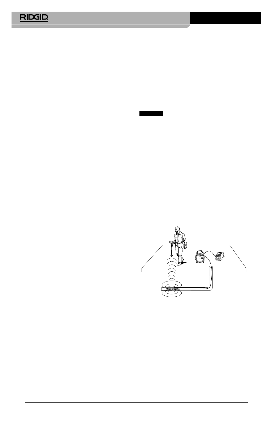
micro CA-350 Muayene ve Gözlem Kamerası
66
TV'ye Bağlama
micro CA‑350 Muayene ve Gözlem Kamerası,
uzaktan görüntüleme veya dahili RCA kablosuy‑
la kaydetme amacıyla bir televizyona veya başka
monitöre bağlanabilir.
Sağ yan bağlantı noktası kapağını açın (Şekil 3).
RCA kablosunu TV‑Çıkışı jakına takın. Kablonun
diğer ucunu, televizyon veya monitör üzerindeki
Video Giriş jakına takın. Video biçimi (NTSC veya
PAL) düzgün ayarlandığından emin olmak
için kontrol edin. Televizyon veya monitörün,
görüntü alımını sağlamak için doğru girişe ayar‑
lanması gerekebilir.Menü'yü kullanarak uygun
TV‑Çıkışı'nı seçin.
SeeSnake
®
Kanal Görüntüleme
Ekipmanı ile Kullanım
micro CA‑350 Muayene ve Gözlem Kamerası aynı
zamanda çeşitli SeeSnake Kanal Görüntüleme
Ekipmanı ile de kullanılabilir ve özellikle microRe‑
el, microDrain™ ve nanoReel Kanal Görüntüleme
Sistemleri ile kullanılmak üzere tasarlanmıştır. Bu
tip ekipmanlarla birlikte kullanıldığında, bu kıla‑
vuzda açıklanan tüm işlevlerini kullanmaya de‑
vam edebilir. micro CA‑350 Muayene ve Gözlem
Kamerası aynı zamanda diğer SeeSnake Kanal
Görüntüleme Ekipmanı ile birlikte sadece görün‑
tüleme ve kaydetme amaçlı olarak kullanılabilir.
SeeSnake Kanal Görüntüleme Ekipmanı ile bir‑
likte kullanmak için, kamera kafası ve tüm kablo
uzantıları kaldırılmalıdır. microReel, microDrain,
nanoReel ve benzeri ekipmanlarda, doğru bağ‑
lantı ve kullanım hakkında bilgi için kullanım
kılavuzuna bakın. Diğer SeeSnake Kanal Görün‑
tüleme Ekipmanı (tipik olarak kablo tamburu ve
monitör), micro CA‑350 Muayene ve Gözlem
Kamerasını SeeSnake Kanal Görüntüleme Ekip‑
manı üzerindeki Video‑Çıkışı bağlantı noktasına
bağlamak için bir adaptör kullanılması gerekir.
bu amaçla bağlandığında micro CA‑350 Mua‑
yene ve Gözlem Kamerası kamera görüntüsünü
görüntüler ve kayıt için kullanılabilir.
SeeSnake Kanal Görüntüleme Ekipmanına (mic‑
roReel, microDrain™ veya nano ‑Reel) bağlarken,
kamera tamburunuza bağlı olan bağlantı modü‑
lünü micro CA‑350 Muayene ve Gözlem Kamarası
üzerindeki kablo bağlantı parçası ile hizalayın ve
sıkı bir şekilde oturacak şekilde düz bir şekilde içe‑
ri kaydırın. (Bkz. Şekil 18.)
Şekil 18 - Kamera Bağlantı Parçası Fişi Takılı
BİLDİRİM
Hasar görmesini önlemek için
bağlantı fişini bükmeyin veya çevirmeyin.
Sondanın Yerinin Bulunması
Sonda ile birlikte kullanıldığında (dahili Verici),
sondaya iki şekilde kumanda edilebilir. Tambur,
sondayı AÇIP KAPATMAK için kullanılabilecek
bir sonda açma/kapama düğmesi ile dona‑
tılmışsa. Aksi takdirde, sonda LED ışık şiddeti
sıfıra düşürülerek AÇILIR. Sonda'nın yerini be‑
lirledikten sonra boruyu incelemeye devam
etmek LED ışığını normal parlaklık düzeyine
ayarlayabilirsiniz.
512 Hz'ye ayarlanmış SR‑20, SR‑60, Scout veya
NaviTrack® II gibi bir RIDGID hat tespit dedektö‑
rü gözlemi yapılan boru içerisindeki kameranın
noktasala olarak konumunu bulmak için kulla‑
nılabilir.
Şekil 19 – Sonda vericinin Yerinin Saptanması
Sonda'nın yerini belirlemek için hat tespit de‑
tektörünü açın ve Sonda moduna ayarlayın.
Hat tespit dedektörü Sonda'yı tespit edene
kadar Sonda'nın bulunabileceği konuma doğ‑
ru tarama yapın. Sonda'nın yerini bulduktan
sonra konumunu tam olarak saptamak için
hat tespit dedekötürünün göstergeleri sıfır de‑
ğerini gösterene kadar taramaya devam edin.
Sonda'nın konumunu saptama ile ilgili ayrıntılı
bilgi için, kullandığınız hat tespit detektörünün
modelinin Kullanım Kılavuzu'na başvurunuz.
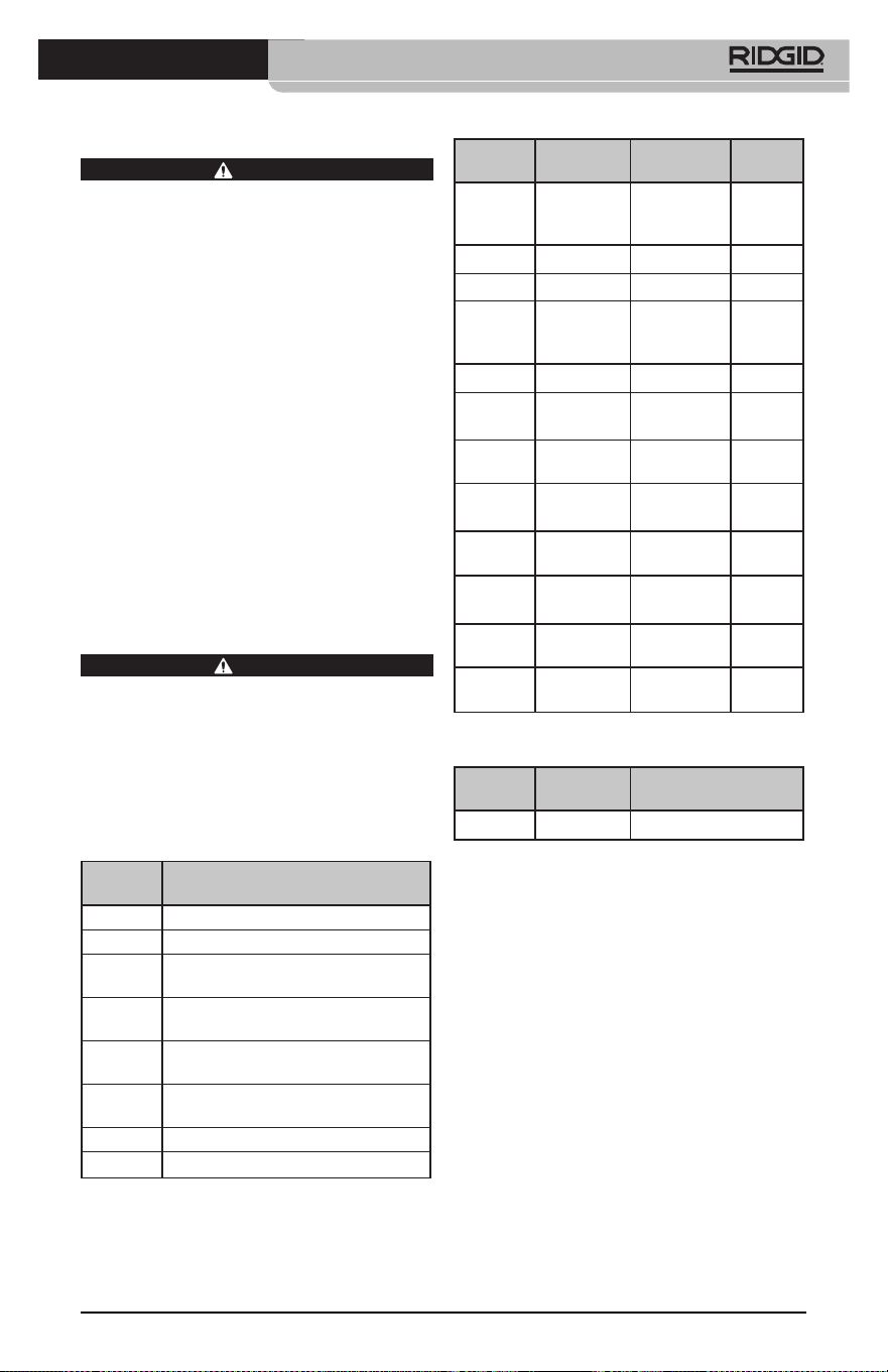
micro CA-350 Muayene ve Gözlem Kamerası
67
Bakım
UYARI
Temizlikten önce pilleri çıkartın.
• Kullanımdan sonra kamera kafasıyla kab‑
losunu her zaman hafif sabun veya deter‑
janla temizleyin.
• Görüntüleme ekranını kuru bir bezle
yavaşça temizleyin. Çok sert bir şekilde
ovalamaktan kaçının.
• Kablo bağlantılarını temizlemek için sa‑
dece alkollü bez kullanın.
• El ekran birimini temiz, kuru bir bezle te‑
mizleyin.
Sıfırlama Fonksiyonu
Ünite işlev göstermeyi bırakır ve çalışmazsa,
Sıfırlama Düğmesine basın (sol yan bağlantı
noktası kapağının altında – Şekil 4). Tekrar
başlatıldığında alet normal çalışmasına de‑
vam edebilir.
İsteğe Bağlı Ekipman
UYARI
Ciddi yaralanma riskini azaltmak için sade‑
ce RIDGID micro CA‑350 Muayene ve Göz‑
lem Kamerası ile birlikte kullanılmak üzere
özel olarak tasarlanmış ve önerilen akse‑
suarları kullanın. Bunların bir listesi aşağı‑
da verilmiştir. Diğer aletlere uygun başka
Aksesuarların micro CA‑350 Muayene ve
Gözlem Kamerası ile kullanılması tehlikeli
olabilir.
Katalog
No. Açıklama
37108 3’
(90 cm) Kablo Uzatması
37113 6' (180 cm) Kablo Uzatması
37103 Kamera Kafası ve 90 cm Kablosu ‑
17 mm
37098 1m uzunluğunda 6 mm çapında
k
amera kafası
37093 4m uzunluğunda 6 mm çapında
kamera kafası
37123 17 mm Aksesuar Paketi (Kanca,
Mıknatıs, Ayna)
36758 AC Adaptörü
40623 Mikrofonlu Kulaklık Aksesuarı
Katalog
No. Bölge F
iş Tipi
55193 Şarj Cihazı
ABD,
Kanada,
Meksika
A
55198 Şarj Cihazı Avrupa C
55203 Şarj Cihazı Çin A
55208 Şarj Cihazı
Avustralya
ve Latin
Amerika
I
55213 Şarj Cihazı Japonya A
55218 Şarj Cihazı İngiltere G
44798
Şarj Cihazı
Kablosu
Kuzey
Amerika
A
44808
Şarj Cihazı
Kablosu
Avrupa C
44803
Şarj Cihazı
Kablosu
Çin A
44813
Şarj Cihazı
Kablosu
Avustralya
ve LA
I
44818
Şarj Cihazı
Kablosu
Japonya A
44828
Şarj Cihazı
Kablosu
İngiltere G
RBC-121 Şarj cihazları ve Kablolar
Katalog
No. Model Kapasite
55183
RB‑1225 12V 2,5Ah
Piller
Listelenen tüm piller katalog numarası RBC‑121 olan herhangi
bir Pil Şarj Cihazı ile çalışacaktır.
Bu alet için kullanılabilecek RIDGID ekip‑
manlarının tam bir listesi için RIDGID.com
adresinden çevrim içi Ridge Tool Kataloğuna
bakın veya (800) 519‑3456'dan Ridge Tool
Teknik Servisini arayın.
Saklama
RIDGID micro CA‑350 Muayene ve Gözlem
Kamerası ‑4°F (‑20°C) ve 140°F (60°C) ve %15
ve%85 RH nem arasında kuru ve güvenli bir
alanda saklanmalıdır.
micro CA‑350 cihazını, çocukların ve aleti kullan‑
ma deneyimi olmayan kişilerin erişemeyeceği
kilitli bir yerde saklayın
Depolama veya nakliye öncesinde pili çıkartın.
micro CA-350 Muayene ve Gözlem Kamerası
68
Servis ve Tamir
UYARI
Hatalı bakım veya onarım RIDGID micro
CA‑350 Muayene ve Gözlem Kamerası'nın
güvenli şekilde çalışmasını önleyebilir.
micro CA‑350 Muayene ve Gözlem Kamerası'nın
bakım ve onarımı bir RIDGID Yetkili Servis Mer‑
kezi tarafından yapılmalıdır.
Size en yakın RIDGID Servis Merkezi veya bakım
veya onarım ile ilgili daha fazla bilgi almak için:
• Bulunduğunuz bölgedeki RIDGID dağıtıcısı
ile iletişim kurun.
• Yerel RIDGID irtibat noktasının iletişim bil‑
gilerine erişmek için RIDGID.com adresini
ziyaret edin.
• RIDGID Teknik Servis Departmanı ile ileti‑
şim kurmak için
rtc[email protected] adresine
yazın veya ABD ve Kanada'da (800) 519‑
3456 numaralı telefonu arayın.
BELİRTİ MUHTEMEL SEBEP ÇÖZÜM
Ekran açılıyor, ama gö-
rüntü yok.
Gevşek kablo bağlantıları. Kablo bağlantılarını kontrol edin, ge‑
rekirse temizleyin. Yeniden bağlayın.
Kamera kafası kırıldı. Kamera kafasını değiştirin.
Döküntü ile kaplanmış kamera
kafası.
Kamera kafasının döküntü ile kap‑
lanmadığından emin olmak için gör‑
sel olarak kontrol edin.
Kamera kafasındaki
LEDl'er azami parlak-
lıkta bile zayıf, ekran
siyah ve beyaz arasın-
da gidip geliyor, renkli
ekran belli bir süreden
sonra kendiliğinden
kapanıyor.
Pil bitiyor. Pili, şarj edilmiş bir pille değiştirin.
Alet açılmıyor. Pilin ömrü dolmuş. Şarj edilmiş bir pille değiştirin.
Aletin sıfırlanması gerekir. Aleti sıfırla. Bkz.“Bakım” Bölümü.
Elden Çıkarma
RIDGID micro CA‑350 Muayene ve Gözlem
Kamerası'nın parçaları değerli malzemeler içerir
ve geri dönüşüme tabi tutulabilir. Bulunduğu‑
nuz bölgede geri dönüşüm konusunda uzman‑
laşmış şirketler bulunabilir. Parçaları geçerli dü‑
zenlemelere göre elden çıkarın. Daha fazla bilgi
için yerel yetkili atık yönetimi birimi ile iletişim
kurun.
AB Ülkeleri için: Elektrikli cihazları
ev atıkları ile birlikte atmayın!
Atık Elektrikli ve Elektronik Cihazlar
için Avrupa Yönergesi 2012/19/EU ve
yerel mevzuata uygulanmasına göre,
kullanılamayacak durumdaki elekt‑
rikli cihazlar ayrı olarak toplanmalı ve çevreye
zarar vermeyecek şekilde elden çıkarılmalıdır.
Sorun Giderme

micro CA-350
Инспекционная видеокамера micro CA-350
Запишите ниже заводской номер и сохраните заводской номер, указанный на фирменной
табличке.
Заводской
№
micro CA-350
Инспекционная
видеокамера
ВНИМАНИЕ!
Прежде чем пользоваться
этим прибором, вниматель-
но прочитайте данное ру-
ководство по эксплуатации.
Непонимание и несоблю-
дение содержания данного
руководства может приве-
сти к поражению электри-
ческим током, пожару и/или
серьезной травме.

Инспекционная видеокамера micro CA-350
70
Содержание
Обозначения техники безопасности ................................................................................................................... 71
Общая информация по технике безопасности ............................................................................................ 71
Безопасность в рабочей зоне ................................................................................................................................. 71
Электробезопасность .................................................................................................................................................. 71
Личная безопасность ................................................................................................................................................... 71
Эксплуатация и обслуживание оборудования ............................................................................................... 72
Использование аккумулятора и уход за ним................................................................................................... 72
Техническое обслуживание...................................................................................................................................... 73
Информация по технике безопасности при работе с данным устройством ............................ 73
Меры безопасности при работе с инспекционной видеокамерой micro CA‑350 ........................ 73
Описание, технические характеристики и стандартные принадлежности .............................. 74
Описание ............................................................................................................................................................................ 74
Технические характеристики .................................................................................................................................. 74
Стандартные принадлежности ............................................................................................................................... 75
Средства управления .................................................................................................................................................. 75
Заявление Федеральной Комиссии Связи США ......................................................................................... 75
Электромагнитная совместимость (ЭМС) ........................................................................................................ 76
Пиктограммы ...................................................................................................................................................................... 76
Сборка прибора ................................................................................................................................................................ 77
Замена/установка батарей ........................................................................................................................................ 77
Питание от адаптера переменного тока ........................................................................................................... 77
Подключение кабеля с головкой формирования изображения
илиудлинительных кабелей ..................................................................................................................................... 77
Установка принадлежностей ................................................................................................................................... 78
Установка флэш‑карты памяти SD™ ............................................................................................................................ 78
Предэксплуатационный осмотр ............................................................................................................................. 78
Подготовка прибора и рабочей зоны ................................................................................................................. 79
Руководство по эксплуатации ................................................................................................................................. 80
Рабочий экран ................................................................................................................................................................. 81
Регулировка изображения ...................................................................................................................................... 82
Фотосъемка ...................................................................................................................................................................... 82
Меню .................................................................................................................................................................................... 83
Отметка времени .................................................................................................................................................. 83
Язык сообщений ................................................................................................................................................... 83
Дата/время .............................................................................................................................................................. 83
ТВ‑выход ................................................................................................................................................................... 83
Обновить микропрограммное обеспечение ............................................................................................ 83
Динамик ................................................................................................................................................................... 84
Автоматическое выключение питания ........................................................................................................ 84
Сброс к заводским настройкам ...................................................................................................................... 84
Сведения о программе
...................................................................................................................................... 84
Перенос изображений в компьютер ................................................................................................................... 84
Подключение к телевизору ...................................................................................................................................... 84
Использование видеокамеры с инспекционным оборудованием SeeSnake
®
............................. 84
Техническое обслуживание ...................................................................................................................................... 85
Функция сброса .............................................................................................................................................................. 85
Дополнительные принадлежности ..................................................................................................................... 85
Хранение прибора ........................................................................................................................................................... 86
Обслуживание и ремонт .............................................................................................................................................. 86
Утилизация ........................................................................................................................................................................... 87
Поиск и устранение неисправностей .................................................................................................................. 88
Пожизненная гарантия
...................................................................................................................Задняя обложка
* Перевод исходных инструкций
Инспекционная видеокамера micro CA-350
71
Обозначения техники безопасности
В данном руководстве по эксплуатации изделия знаки техники безопасности и сигналь‑
ные слова используются для сообщения важной информации по безопасности. В дан‑
ном разделе объясняется значение этих сигнальных слов и знаков.
Это знак обозначения опасности. Он используется для предупреждения о травма‑
тических опасностях. Соблюдайте требования всех сообщений по технике безопас‑
ности, которые следуют за данным знаком, чтобы избежать возможных травм или
летального исхода.
ОПАСНО
ВНИМАНИЕ
ОСТОРОЖНО
ПРЕДУПРЕЖДЕНИЕ
ОПАСНО указывает на опасную ситуацию, которая, если ее не избежать, при‑
ведет к летальному исходу или к значительной травме.
ВНИМАНИЕ указывает на опасную ситуацию, которая, если ее не избежать,
может привести к летальному исходу или к значительной травме.
ОСТОРОЖНО указывает на опасную ситуацию, которая, если ее не избе‑
жать, может привести к незначительной травме или к травме средней
тяжести.
ПРЕДУПРЕЖДЕНИЕ указывает на информацию, относящуюся к защите
имущества.
Этот знак означает "внимательно прочитайте руководство по эксплуатации перед
использованием оборудования". Руководство по эксплуатации содержит важную
информацию по безопасной и надлежащей работе с оборудованием.
Этот знак означает "всегда надевайте защитные очки с боковыми щитками или за‑
крытые защитные очки при транспортировке или эксплуатации данного оборудо‑
вания, чтобы снизить риск травмирование глаз".
Этот знак указывает на риск того, что руки, пальцы или другие части тела могут быть
защемлены или затянуты в привод или другие движущиеся части.
Этот знак указывает на опасность поражения электрическим током.
Общая информация по
технике безопасности
ВНИМАНИЕ
Прочтите все предупреждения относи‑
тельно безопасного использования и все
инструкции. Несоблюдение этих преду‑
преждений и инструкций может приве‑
сти к поражению электрическим током,
пожару и/или серьезной травме.
СОХРАНИТЕ НАСТОЯЩУЮ
ИНСТРУКЦИЮ!
Безопасность в рабочей зоне
• Рабочая зона должна быть расчище-
на и хорошо освещена. Несчастные
случаи происходят, как правило, в
загроможденных и слабо освещен‑
ных зонах.
• Недопустимо использовать обору-
дование во взрывоопасных средах,
то есть вблизи горючих жидкостей,
газов или пыли. При работе с обо‑
рудованием могут появиться искры,
что может привести к воспламене‑
нию пыли или газов.
• Не допускается присутствие детей и
посторонних лиц во время работы с
оборудованием. Отвлечение внима‑
ния может привести к потере управ‑
ления оператором.
Электробезопасность
• Не прикасайтесь к заземленным по-
верхностям, например, трубам, на-
гревателям, кухонным плитам и хо-
лодильникам. В противном случае,
если тело человека заземлено, риск
поражения током повышается.
• Берегите оборудование от дождя и
влаги. Проникновение воды внутрь
оборудования увеличивает опасность
поражения током.
Личная безопасность
• Будьте внимательны, контроли-
руйте выполняемые действия и
пользуйтесь здравым смыслом
при работе с прибором. Запре-
щается эксплуатировать прибор,

Инспекционная видеокамера micro CA-350
72
находясь в уставшем состоянии или
под действием наркотиков, алкого-
ля или лекарственных пре па ратов.
Потеря концентрации при работе с
оборудованием может привести к
серьезным травмам.
• Не следует дотягиваться к рабочим
частям машины с большого рас-
стояния. Всегда сохраняйте устой-
чивое положение и равновесие.
Это обеспечивает более уверенное
владение прибором в непредсказуе‑
мых ситуациях.
• Используйте индивидуальные сред-
ства за щиты. Всегда используйте сред‑
ства защиты глаз. Использование в
соответствующих условиях пылезащит‑
ной маски, ботинок с нескользящими
подошвами, каски, берушей или других
защитных средств снижает травмоопас‑
ность.
Эксплуатация и обслуживание
оборудования
• Не перегружайте оборудование. Ис-
пользуйте соответствующее обору-
дование для каждого типа работы.
Правильный выбор оборудования в
соответствии с задачей способству‑
ет более качественному, безопасно‑
му и быстрому выполнению работы.
• Не используйте оборудование, если
его переключатель не переводится
в положение "ВКЛ" или "ВЫКЛ". Лю‑
бой прибор с неисправным выклю‑
чателем электропитания опасен, его
следует отремонтировать.
• Перед выполнением любых ре-
гулировок, замены принадлеж-
ностей или постановкой прибора
на хранение следует вытащить из
него батарейки электропитания.
Подобные меры предосторожности
снижают травмоопасность.
• Храните неиспользуемое оборудо-
вание вдали от детей. Не допускай-
те использование оборудования ли-
цами, не работавшими с ним ранее
и не ознакомленными с данными
инструкциями. Оборудование может
представлять опасность в руках не‑
квалифицированных пользователей.
• Следите за состоянием оборудова-
ния. Проверяйте отсутствие деталей,
их поломку и другие нарушения,
которые могут повлиять на работу
прибора. В случае повреждения обо‑
рудования перед работой, устраните
неполадки. Неисправное техническое
состояние приборов является причи‑
ной многих несчастных случаев.
• Используйте оборудование и при-
надлежности в соответствии с на-
стоящим руководством, принимая
во внимания условия и цели эксплу-
атации. Использование оборудова‑
ние не по назначению может стать
причиной опасной ситуации.
• Используйте только принадлежно-
сти, рекомендованные производи-
телем для данного прибора. Принад‑
лежности, подходящие для работы с
одним оборудованием, могут быть
опасными при использовании с дру‑
гим.
• Следите за тем, чтобы ручки прибо-
ра оставались сухими и чистыми; не
допускайте попадания на них масла
или смазки. Это обеспечит лучшее
управление оборудованием.
Использование аккумулятора и
уход за ним
• Заряжайте аккумуляторы только
с помощью зарядного устройства,
указанного изготовителем. Зарядное
устройство, подходящее для аккуму‑
ляторов одного типа, может быть по‑
жароопасным при зарядке аккумуля‑
торов другого типа.
• Используйте оборудование только с
соответствующими аккумуляторами.
Использование любых других акку‑
муляторов может создать опасность
травмирования или пожара.
• Неиспользуемый аккумулятор хра-
ните в стороне от металлических
предметов, таких как скрепки для бу-
маг, монеты, ключи, гвозди, винты и
другие мелкие металлические пред-
меты, которые могут соединить нако-
ротко клеммы аккумулятора. Корот‑
кое замыкание клемм аккумулятора
может явиться причиной ожога или
пожара.
• В случае нарушения правил эксплу-
атации из аккумулятора может вы-
текать жидкий электролит; не допу-
скайте контакта с электролитом. При
случайном попадании электролита на
кожу, смойте его водой. При попада‑
нии электролита в глаза промойте их

Инспекционная видеокамера micro CA-350
73
водой и обратитесь к врачу. Вытека‑
ющий из аккумулятора жидкий элек‑
тролит может вызвать раздражение
или ожог.
Техническое обслуживание
• Ремонт оборудования должен осу-
ществлять квалифицированный пер-
со нал с использованием оригиналь-
ных запасных частей. Только таким
образом гарантируется безопасность
при использовании прибора.
Информация по технике
безопасности при работе
с данным устройством
ВНИМАНИЕ
Данный раздел содержит важную инфор‑
мацию по безопасности, специфическую
для данной инспекционной видеокаме‑
ры.
Чтобы снизить риск поражения электро‑
током или получения другой тяжелой
травмы, перед использованием инспек‑
ционной видеокамеры micro CA‑350
RIDGID® внимательно ознакомьтесь с ука‑
занными мерами предосторожности.
СОХРАНИТЕ НАСТОЯЩУЮ
ИНСТРУКЦИЮ!
В переносной сумке инспекционной видео‑
камеры micro CA‑350 имеется кармашек для
руководства, для того чтобы оператор всегда
носил руководство вместе с оборудованием.
Меры безопасности при работе
с инспекционной видеокамерой
micro CA‑350
• Не подвергайте блок дисплея воз-
действию воды или дождя. Это по-
вышает риск поражения электриче-
ским током. Головка формирования
изображения видеокамеры micro
CA‑350 и кабель имеют водозащит‑
ное исполнение до глубины погруже‑
ния 10 футов (3 метра). Переносной
блок дисплея не имеет водозащитно‑
го исполнения.
• Не пользуйтесь инспекционной ви-
деокамерой micro CA-350 там, где
может присутствовать электриче-
ское напряжение. Это повышает риск
поражения электрическим током.
• Не кладите инспекционную виде-
окамеру micro CA-350 в такие ме-
ста, где присутствуют движущиеся
детали механизмов. Это повышает
риск травм при попадании частей
тела в движущиеся детали.
• Не используйте этот прибор для ос-
мотра людей или какой-либо иной
медицинской цели. Это не меди‑
цинский прибор. Такое применение
прибора может привести к травмам.
• Всегда используйте соответствую-
щие индивидуальные средства за-
щиты при переноске и эксплуата-
ции инспекционной видеокамеры
micro CA-350. В канализационных
стоках и в других зонах могут при‑
сутствовать химические вещества,
бактерии и другие материалы, ко‑
торые могут быть токсичными, за‑
разными, могут причинять ожоги
или наносить иные травмы. В состав
соответствующих средств индиви-
дуальной защиты всегда должны
входить защитные очки и перчат-
ки, а также могут входить латексные
или резиновые перчатки, защитные
маски для лица, закрытые защитные
очки, защитные комбинезоны, респи‑
раторы и обувь со стальным носком.
• Соблюдайте гигиену. Мойте руки и
другие части тела, соприкасавшиеся с
содержанием водостоков, горячей во‑
дой с мылом после переноски инспек‑
ционной видеокамеры micro CA‑350
или работы по осмотру водостоков и
других зон, которые могут содержать
химикаты или бактерии. Не ешьте и
не курите во время работы или пере‑
носки инспекционной видеокамеры
micro CA‑350. Это поможет предот‑
вратить заражение токсичными или
инфекционными веществами.
• Запрещается работать с инспекци-
онной видеокамерой micro CA-350,
если оператор или прибор находят-
ся в воде. Работа с электроприбором
в воде повышает риск удара током.
Декларация соответствия ЕC (890‑011‑320.10)
выпускается отдельным сопроводительным
буклетом к данному руководству только по
требованию.

Инспекционная видеокамера micro CA-350
74
Если у вас возникли вопросы, касающиеся
этого изделия RIDGID®:
– Обратитесь к местному дистрибьюто‑
ру RIDGID.
– Чтобы найти контактный телефон
местного дистрибьютора RIDGID, во‑
йдите на сайт RIDGID.com.
– Обратитесь в Отдел технического
обслуживания RIDGID по адресу
rtc[email protected], в США и
Канаде вы также можете позвонить по
телефону (800) 519‑3456.
Описание, технические
характеристики
и стандартные
принадлежности
Описание
Инспекционная видеокамера micro CA‑350
RIDGID представляет собой мощное пере‑
носное устройство цифровой записи. Пол‑
ностью цифровая платформа позволяет
вам записывать фото‑ и видеоизображе‑
ния при осмотре труднодоступных мест.
Некоторые функции управления изобра‑
жением, такие как поворот изображения
и цифровое масштабирование встроены
в систему, что обеспечивает подробный
и точный визуальный осмотр. К прибору
можно подключить внешнюю память или
использовать функцию вывода изображе‑
ния на телевизор. Принадлежности (зер‑
кало, крючок и магнит), прикрепляемые к
головке формирования изображений, вхо‑
дят в комплект и расширяют возможности
применения.
Технические характеристики
Рекомендуемое
использование...........
В закрытых
помещениях
Видимое
расстояние...................
от 0.4" (10 мм) до ∞
Дисплей.........................
Цветной TFT‑дисплей
с диагональю
3.5 дюйма (90 мм)
(разрешающая
способность
320 x 240)
Головка
видеокамеры..............
3
/
4
" (17 мм)
Подсветка...................... 4 светодиода с
регулируемой
яркостью
Рабочая длина
кабеля.............................
3' (90 см), с возм.
удлинения до 30' (9 м)
с помощью дополн.
удлинителей; головка
формирования
изображения и
кабель имеют
водозащищенное
исполнение до
глубины 10' (3 м), класс
защиты IP67
Формат
фотоизображений....
JPEG
Разрешающая
способность
фотоизображений....
640 x 480
Формат
видеоизображений.
MP4
Разрешающая
способность
видеоизображений.
640 x 480
Частота кадров........... до 30 кадров/с
Выход
телевизионного
сигнала TV‑Out..........
PAL/NTSC
переключается
пользователем
Встроенная память. Память 235 МБ
Внешняя память....... Карта SD™ макс.
емкостью 32 ГБ
(в комплекте 8 ГБ)
Вывод данных............
По USB‑кабелю
данных и на карту
памяти SD™
Диапазон рабочих
температур.................
от 32°F до 113°F
(от 0°C до 45°C)
Температура
хранения......................
от ‑4°F до 140°F
(от ‑20°C до 60°C)
Электропитание....... Литий‑ионная
батарея напр. 12 В,
адаптер переменного
тока 12 В, 3 A
Вес................................... 5.5 фунта (2,5 кг)

Инспекционная видеокамера micro CA-350
75
Рис. 3 - Крышка гнезд с правой стороны
прибора
Встроенный
микрофон
Гнездо для
наушников
Динамик
Адаптер
переменного
тока
Рис. 4 - Крышка гнезд с левой стороны
прибора
Кнопка "Сброс"
Выход
телевизионного
сигнала TV-Out
Разъем Mini-B
USB
Слот SD™
Заявление Федеральной
Комиссии Связи США
Данный прибор был протестирован и по‑
казал соответствие с ограничениями для
Класса В цифровых устройств, в соответ‑
ствии с Частью 15 Правил ФКС. Эти огра‑
ничения представляют собой обоснован‑
ную защиту против недопустимых помех в
жилых помещениях.
Этот прибор генерирует, использует и мо‑
жет излучать энергию радиочастот, и, если
он не будет установлен и использован в
соответствии с руководством, может соз‑
давать недопустимые помехи для радио‑
связи.
Однако нет гарантий, что в каком‑то кон‑
кретном случае не случится помех.
Стандартные принадлежности
В комплект инспекционной видеокамеры
micro CA‑350 входят следующие элементы:
• Наушники micro CA‑350
• Головка формирования изображения 17 мм
• USB‑кабель длиной 3 фута (90 см)
• RCA‑кабель с проводом звукового сиг‑
нала длиной 3 фута (90 см)
• Комплект приспособлений: крючок, маг‑
нит и зеркало
• Литий‑ионная батарея 12 В
• Зарядное устройство для литий‑ионной
батареи со шнуром питания
• Адаптер переменного тока
• Наушники с микрофоном
• Флэш‑карта памяти SD™ емкостью 8 ГБ
• Руководство по эксплуатации
Рис. 1 - Инспекционная видеокамера
micro CA-350
Средства управления
Затвор
Меню
Выбрать/
Подтвердить
Возврат
Затвор
Рис. 2 - Средства управления
Поворот
изображения
Стрелки
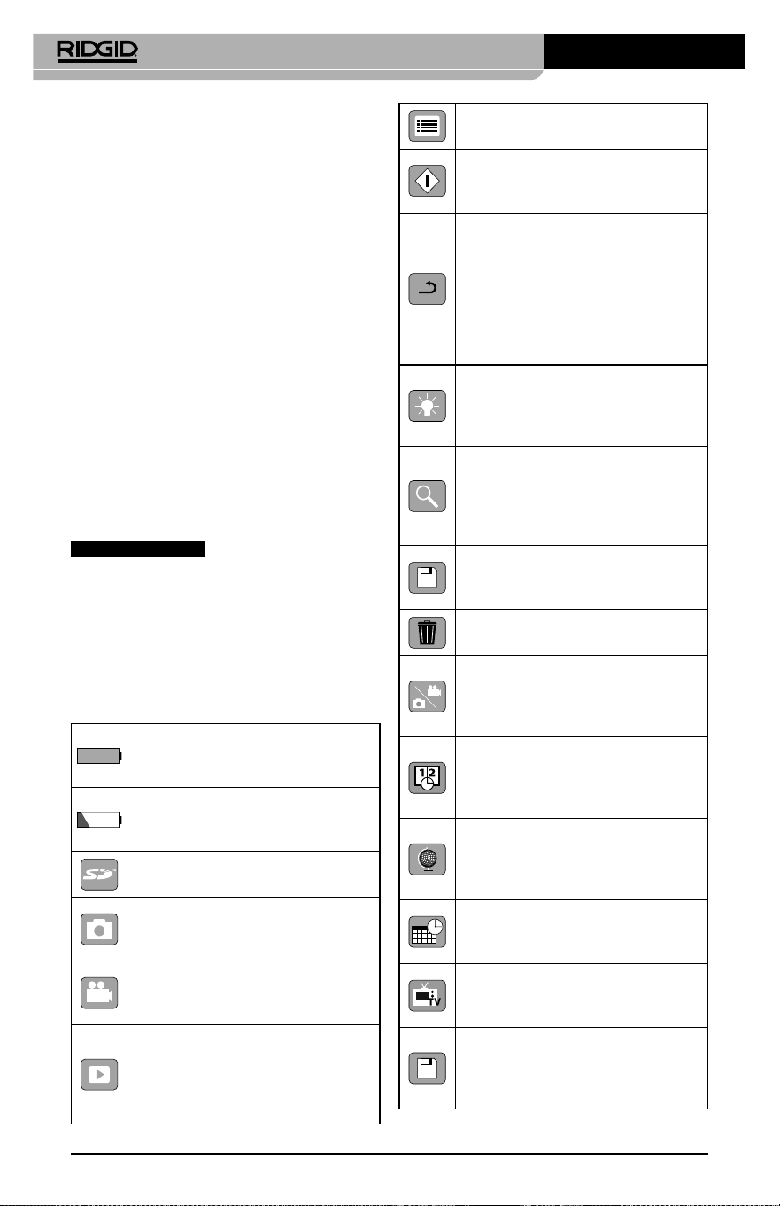
Инспекционная видеокамера micro CA-350
76
Меню – Выбрав этот значок, Вы
перейдете в опцию Меню.
Выбор – Нажав кнопку "Выбор"
на рабочем экране, Вы перейдете
к экрану воспроизведения.
Ввод – Нажав кнопку "Ввод"
на рабочем экране, Вы
переключитесь из режима
фотокамеры в режим
видеокамеры. Нажатием
кнопки "Ввод" также можно
вернуться из меню и из режима
воспроизведения.
Яркость светодиодов –
Нажимайте кнопки со стрелками
Вправо и Влево, чтобы изменить
яркость светодиодов.
Масштаб изображения –
Нажимайте кнопки со стрелками
Вверх и Вниз, чтобы изменить
масштаб изображения от 1.0x до
2.5x
Сохранить – Показывает, что
снимок или видео сохранены в
памяти.
Мусорная корзина – Значок
подтверждения удаления.
Режим – Позволяет выбрать
режим съемки фотоизображения,
видеоизображения или
воспроизведения.
Отметка времени – Позволяет
выбрать режим отображения
или скрытия реальной даты и
времени на экране.
Язык – Выберите язык:
английский, французский,
испанский, немецкий,
голландский, итальянский, и т.д.
Время и дата – Выберите эту
опцию, чтобы установить время
и дату.
TV – Выбор формата
NTSC или PAL для вывода
видеоизображения на телевизор.
Обновить программное
обеспечение – Используется
для обновления программного
обеспечения прибора.
Индикатор состояния
батареи– Батарея полностью
заряжена.
Индикатор состояния
батареи– Остается менее 25%
заряда батареи.
Карта SD™ – Показывает, что SD‑
карта вставлена в прибор.
Фотоаппарат – Показывает,
что прибор работает в режиме
фотоаппарата.
Видеокамера – Показывает,
что прибор работает в режиме
видеокамеры.
Режим воспроизведения –
Выбрав этот значок, Вы можете
просматривать и удалять
сохраненные ранее снимки и
видео.
Если данный прибор создает недопусти‑
мые помехи для радио либо телевизи‑
онного приема, что можно определить
ВКЛЮЧАЯ и ВЫКЛЮЧАЯ прибор, пользо‑
ватель может попробовать исправить по‑
мехи следующими способами:
• Переориентировать либо переместить
принимающую антенну.
• Увеличить дистанцию между прибором
и приемником.
• Получить консультацию у дилера либо
опытного техника по радио/ТВ.
Электромагнитная
совместимость (ЭМС)
Термин "электромагнитная совместимость"
использован с целью обозначить способ‑
ность продукта безошибочно функциони‑
ровать в среде с излучаемыми электромаг‑
нитными помехами и электростатическими
разрядами, не создавая электромагнитных
помех другому оборудованию.
ПРЕДУПРЕЖДЕНИЕ
Инспекционная видео‑
камера RIDGID micro CA‑350 соответствует
всем действующим стандартам по элек‑
тромагнитной совместимости ЭМС. Одна‑
ко, невозможно полностью исключить ве‑
роятность создания прибором помех для
других устройств.
Пиктограммы
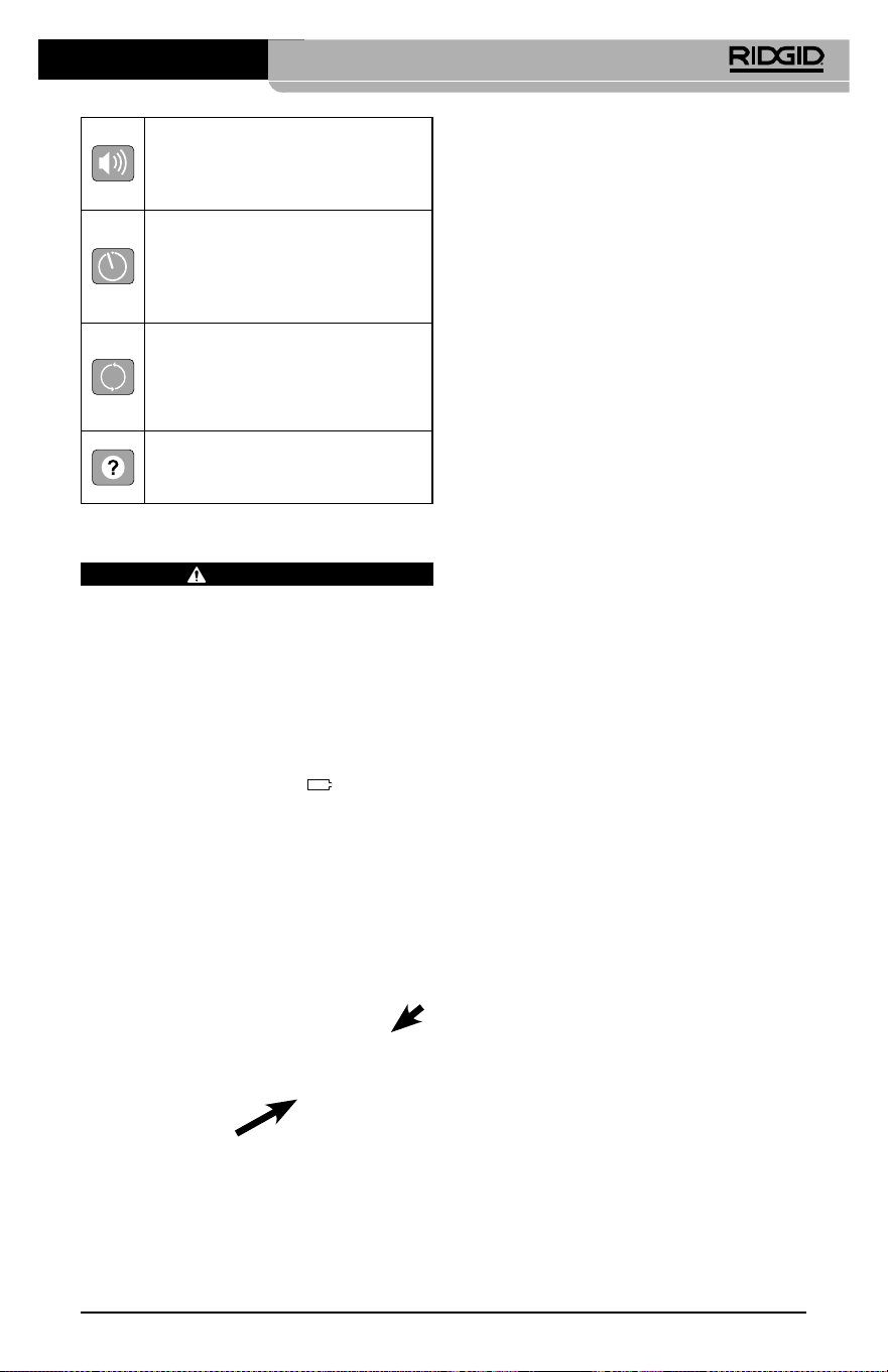
Инспекционная видеокамера micro CA-350
77
Сборка прибора
ВНИМАНИЕ
Для снижения риска тяжелых травм во
время использования выполняйте дан‑
ные процедуры надлежащей сборки
прибора.
Замена/установка батарей
Инспекционная видеокамера micro СА‑350
поставляется без установленной батареи
питания. Если на дисплее прибора появля‑
ется индикатор батарейки
, то разря‑
женную батарею прибора следует зарядить.
Прежде чем убирать прибор на хранение,
извлеките аккумулятор.
1. Сожмите выступы аккумулятора (см.
рис. 5) и вытяните его наружу.
Рис. 5 - Извлечение/вставка аккумулятора
2. Вставьте аккумулятор контактами в
камеру для видеодиагностики, как по‑
казано на рис. 5.
Питание от адаптера
переменного тока
Питание инспекционной видеокамеры micro
CA‑350 можно также осуществлять от имею‑
щегося в комплекте адаптера переменного
тока.
1. Откройте крышку гнезд с правой сто‑
роны прибора (рис. 3).
2. Сухими руками подсоедините вилку
адаптера переменного тока к розетке.
3. Вставьте цилиндрический штекер адап‑
тера переменного тока в гнездо с мар‑
кировкой "DC 12V" ("Напряжение 12 В
пост. тока").
Рис. 6 - Питание прибора от адаптера
переменного тока
Подключение кабеля с головкой
формирования изображения или
удлинительных кабелей
Чтобы использовать инспекционную ви‑
деокамеру micro CA‑350, необходимо при‑
соединить кабель с головкой формиро‑
вания изображения к переносному блоку
дисплея. Перед подсоединением кабеля к
переносному блоку дисплея, удостоверь‑
тесь, что ключ и прорезь (рис. 7) совмеще‑
ны надлежащим образом. После этого от
руки затяните цилиндрическую ручку с на‑
каткой, чтобы зафиксировать соединение.
Динамик/микрофон – Включает
или выключает динамик или
микрофон во время записи и
воспроизведения.
Автоматическое отключение
питания – Прибор
автоматически отключается
через 5, 15 или 60 минут
бездействия.
Сброс к заводским
установкам– Восстанавливает
заводские установки по
умолчанию.
Сведения о программе–
Показывает версию
программного обеспечения.
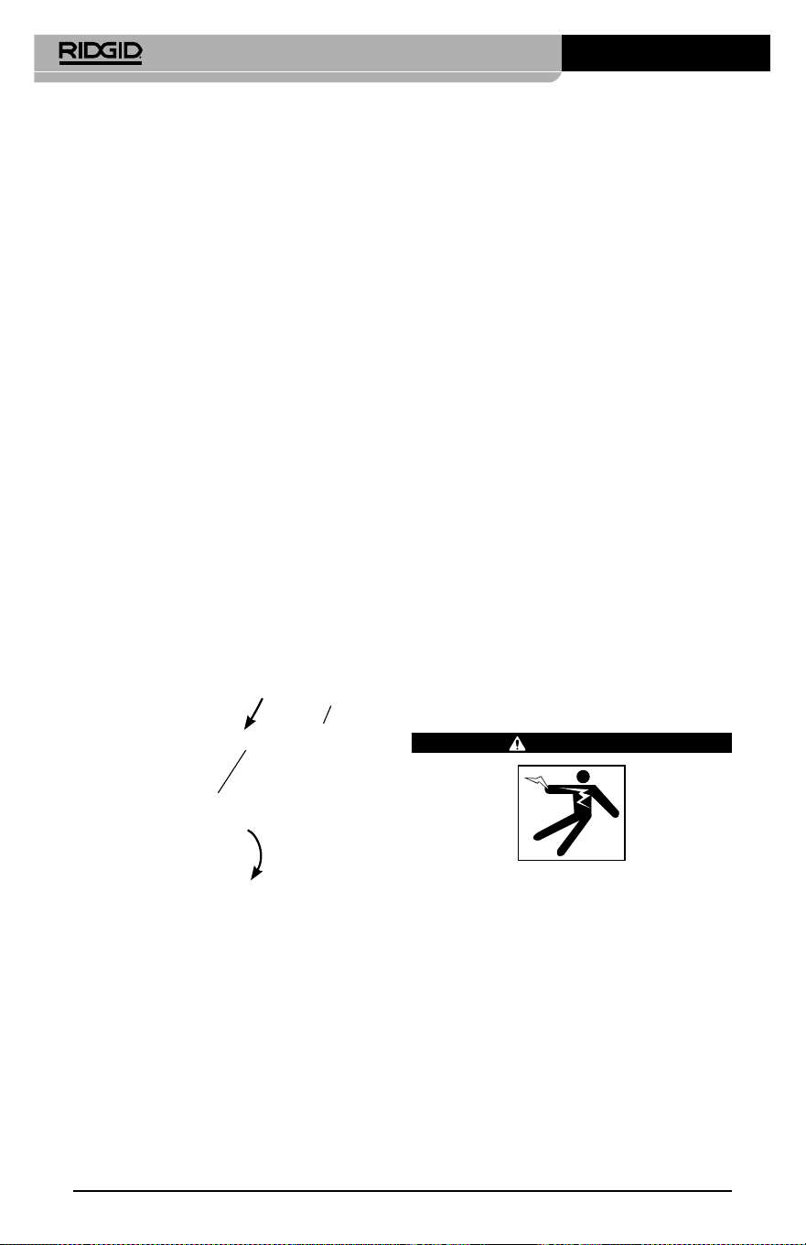
Инспекционная видеокамера micro CA-350
78
Рис. 7 - Кабельные соединения
Чтобы увеличить длину кабеля видеока‑
меры до 30 футов (9 м), можно использо‑
вать имеющиеся в комплекте удлинители
кабелей длиной 3 фута (90 см) и 6 футов
(180 см). Чтобы подсоединить удлинитель‑
ный кабель, сначала отсоедините кабель
головки видеокамеры от дисплейного
блока, отвернув цилиндрическую ручку с
накаткой. Подсоедините удлинительный
кабель к переносному дисплею, как опи‑
сано выше (рис. 7). Присоедините конец
с ключом кабеля головки видеокамеры к
концу с прорезью удлинительного кабеля
и от руки затяните цилиндрическую ручку
с накаткой для фиксации соединения.
Установка принадлежностей
Все три приспособления (крючок, магнит
и зеркало), входящие в комплект прибора,
присоединяются к головке формирования
изображения аналогичным образом.
Рис. 8 - Установка принадлежности
Принадлежность
¼ оборота
Фаски
Чтобы прикрепить приспособление, не‑
обходимо удерживать головку формиро‑
вания изображения так, как показано на
рис. 8. Вставьте полукруглый конец при‑
способления на лыски головки формиро‑
вания изображения. Затем для фиксации
поверните приспособление на 1/4 обо‑
рота.
Установка флэш‑карты памяти SD™
Откройте крышку гнезд с левой стороны
прибора (рис. 4), чтобы получить доступ
к слоту для установки SD‑карты. Вставьте
SD‑карту в слот срезанным уголком вверх,
как показано на пиктограмме рядом со
слотом (рис. 9
). SD‑карты вставляются только
в одном положении, поэтому не следует при‑
лагать усилий. После установки SD‑карты, в
левом верхнем углу экрана появится неболь‑
шой значок SD‑карты, с указанием количества
снимков и продолжительности видеозаписи,
которые можно сохранить на SD‑карте.
Рис. 9 - Установка SD-карты
Предэксплуатационный
осмотр
ВНИМАНИЕ
Перед каждым использованием осма‑
тривайте инспекционную видеокамеру,
устраняйте малейшие неисправности,
чтобы снизить риск серьезной травмы
в результате поражения током и других
причин, а также чтобы предотвратить
выход прибора из строя.
1. Убедитесь, что прибор ВЫКЛЮЧЕН.
2. Извлеките батарею и осмотрите ее на
предмет повреждений. При необходи‑
мости замените батарею. Запрещается
использовать инспекционную видео‑
камеру с поврежденной батареей.
Инспекционная видеокамера micro CA-350
79
3. Удалите с прибора любое масло, смаз‑
ку или грязь. Это поможет предотвра‑
тить выскальзывание прибора из рук.
4. Осмотрите инспекционную видеока‑
меру micro CA‑350 и убедитесь в от‑
сутствии поврежденных, изношенных,
утерянных или заедающих деталей
или любых других неисправностей,
которые могут помешать нормальной
и безопасной работе.
5. Осмотрите и проверьте отсутствие кон‑
денсата в объективе головки видеока‑
меры. Во избежание повреждения при‑
бора, не используйте видеокамеру, если
внутри объектива имеется конденсат.
Дайте воде испариться, прежде чем сно‑
ва использовать прибор.
6. Осмотрите кабель по всей длине и убеди‑
тесь в отсутствии трещин или поврежде‑
ний. Через поврежденный кабель в при‑
бор может попасть вода, что повышает
риск поражения электрическим током.
7.
Проверьте герметичность соединений
между переносным прибором, удлини‑
тельными кабелями и кабелем головки
формирования изображения. Водонепро‑
ницаемость кабеля обеспечивается при
надлежащей сборке всех его соединений.
Убедитесь, что прибор собран правильно.
8. Проверьте, на месте ли предупреди‑
тельные этикетки, хорошо ли они при‑
креплены и разборчивы (рис. 10).
Рис. 10 - Предупреждающая этикетка
9.
Если во время проверки были обнаруже‑
ны какие‑либо неисправности, не поль‑
зуйтесь инспекционной видеокамерой
до их устранения и выполнения надле‑
жащего технического обслуживания.
10.
Сухими руками вновь установите батарею.
11. Нажмите и удерживайте кнопку пита‑
ния в течение одной секунды. Лампы
головки формирования изображения
должны загореться, затем появится
экран заставки. После подготовки ви‑
деокамеры к работе на экране появит‑
ся изображение в реальном времени,
формируемое видеокамерой. Если
изображение на экране не появится,
обратитесь к разделу "Поиск и устра-
нение неисправностей" данного руко‑
водства.
12. Чтобы ВЫКЛЮЧИТЬ прибор, нажмите
и удерживайте кнопку питания в тече‑
ние одной секунды.
Подготовка прибора и
рабочей зоны
ВНИМАНИЕ
Настройте инспекционную видеокаме‑
ру micro CA‑350 и организуйте рабочую
зону в соответствии с указанными про‑
цедурами для того, чтобы снизить риск
травм от поражения электрическим то‑
ком, попадания в движущиеся детали
механизмов и других причин, а также
предотвратить повреждение прибора.
1. Проверьте в рабочей зоне:
• Соответствующее освещение.
• Отсутствие легковоспламеняющих‑
ся жид кос тей, паров или горючей
пыли. Если такие условия имеются,
не следует приступать к работе в
этой зоне до тех пор, пока источ‑
ники опасностей не будут опреде‑
лены и устранены. Инспекционная
видеокамера micro CA‑350 не имеет
взрывозащищенного исполнения и
может создавать искры.
• Чистое, ровное, устойчивое и сухое
место для оператора. Не применяй‑
те инспекционную видеокамеру,
стоя в воде.
2. Осмотрите зону или пространство, ко‑
торое вы собираетесь обследовать, и
определите, соответствует ли инспек‑
ционная видеокамера micro CA‑350
этой задаче.
Инспекционная видеокамера micro CA-350
80
• Определите точки доступа к месту.
Минимальный диаметр отверстия, в
которое может пройти 17‑миллиме‑
тровая головка видеокамеры, состав‑
ляет примерно 3/4 дюйма (19 мм).
• Определите расстояние до исследу‑
емого объекта. К видеокамере мож‑
но дополнительно подсоединить уд‑
линительные кабели до достижения
длины 30 футов (9 м).
• Определите, имеются ли какие‑либо
препятствия, из‑за которых кабель
придется круто поворачивать. Ка‑
бель инспекционной видеокамеры
может без повреждений войти в от‑
верстие радиусом 5 дюймов (13 см).
• Определите, имеется ли в проверяе‑
мой зоне электропитание. Если да, то
электропитание в этой зоне необхо‑
димо ОТКЛЮЧИТЬ, чтобы уменьшить
риск поражения электрическим током.
Используйте соответствующие про‑
цедуры отключения питания и наве‑
шивания замков на рубильники, что‑
бы предотвратить повторную подачу
электропитания во время осмотра.
• Определите, могут ли во время осмо‑
тра встретиться какие‑либо жидкости.
Головка формирования изображения
видеокамеры и кабель имеют водо‑
защитное исполнение до глубины по‑
гружения 10 футов (3метра). На боль‑
ших глубинах вода может проникнуть
в кабель и в головку формирования
изображения, что приведет к удару
током либо повреждению оборудова‑
ния. Переносной блок дисплея имеет
водозащитное исполнение (IP54), но
его не следует погружать в воду.
• Определите, имеются ли в контроли‑
руемой зоне какие‑либо химикаты,
особенно при проверке канализаци‑
онных трубопроводов. Очень важно
понимать необходимость особых
мер безопасности для работы в при‑
сутствии химикатов. Свяжитесь с
производителем химикатов для по‑
лучения необходимой информации.
Химикаты могут повредить или испо‑
ртить инспекционную видеокамеру.
• Определите температуру зоны и
предметов в зоне. См. Технические
характеристики. При использова‑
нии прибора в зонах, где температу‑
ра превышает указанный диапазон,
или касание видеокамерой более
горячих или холодных объектов мо‑
жет привести к выходу ее из строя.
• Определите, есть ли в осматривае‑
мой зоне движущиеся детали меха‑
низмов. Если да, привод этих дета‑
лей необходимо отключить, чтобы
предотвратить движение во время
осмотра с тем, чтобы снизить риск
попадания частей тела в движу‑
щиеся детали. Используйте соответ‑
ствующие процедуры выключения
питания и навешивания замков на
рубильники, чтобы предотвратить
повторное включение движущихся
деталей во время осмотра.
Если инспекционная видеокамера micro
CA‑350 не является подходящим при‑
бором для этой работы, имеется другое
инспекционное оборудование RIDGID.
Полный перечень продукции RIDGID при‑
веден в каталоге RIDGID в сети Интернет
на сайте RIDGID.com
3. Перед каждым применением инспек‑
ционную видеокамеру micro CA‑350
необходимо надлежащим образом ос‑
мотреть и проверить.
4. Установите требуемые для выполне‑
ния задания дополнительные принад‑
лежности.
Руководство по
эксплуатации
ВНИМАНИЕ
Всегда надевайте средства защиты ор‑
ганов зрения, чтобы защитить глаза от
грязи и других инородных тел.
Выполняйте требования инструкции по
эксплуатации, чтобы уменьшить риск
поражения электрическим током, попа‑
дания в движущиеся детали механизмов
или других причин.
1. Убедитесь, что инспекционная видео‑
камера правильно настроена, а рабо‑
чая зона организована должным обра‑
зом, и в ней отсутствуют посторонние
лица и другие отвлекающие моменты.

Инспекционная видеокамера micro CA-350
81
2. Нажмите и удерживайте кнопку пи‑
тания в течение двух секунд. Лампы
головки формирования изображения
должны ЗАГОРЕТЬСЯ, затем появится
экран заставки Этот экран указывает,
что прибор запускается. После полно‑
го включения прибора экран заставки
автоматические переключится на ра‑
бочий экран.
Рис. 11 - Экран-заставка
(Примечание. Версия меняется с
каждым обновлением микропро-
граммного обеспечения.)
Рабочий экран
Рабочий экран ‑ это экран, на котором вы
выполняете большую часть своей работы.
На экран выводится изображение с виде‑
окамеры в реальном времени. Вы можете
изменять масштаб изображения, настраи‑
вать яркость светодиодов, сохранять фото‑
или видеоизображение с этого экрана.
В верхней части экрана имеется строка со‑
стояния, показывающая режим прибора,
масштаб, значок флэш‑карты SD™ (если она
установлена в прибор), объем доступной
памяти и ВКЛ/ВЫКЛ состояние динамика/
микрофона. Если включена отметка време‑
ни, нижняя строка показывает дату и время.
Рис. 12 - Рабочий экран
Информационная
строка
Строка
состояния
После ВКЛЮЧЕНИЯ инспекционной видео‑
камеры режим по умолчанию – захват не‑
подвижных изображений.
После нажатия кнопки меню в любое время
осуществляется выход в меню. Меню откры‑
вается поверх экрана с изображением от
видеокамеры в реальном времени. Чтобы
переключаться по категориям меню, вос‑
пользуйтесь кнопками со стрелками вправо
и влево
. Используйте кнопки со стрел‑
ками вверх и вниз
, чтобы переходить
между позициями меню, для выбора требу‑
емой опции нажимайте кнопку выбора
.
Рис. 13 - Копия экрана выбора режима
3. Если необходимо отрегулировать другие
настройки инспекционной видеокамеры
(отметку времени, язык, дату/время, ТВ‑
выход, обновление микропрограммного
обеспечения, динамик/микрофон, авто‑
матическое выключение питания, сброс
к заводским настройкам), обратитесь к
разделу "Меню".
4. Приготовьте камеру для осмотра. Воз‑
можно, будет необходимо придать ка‑
белю с камерой особую форму, либо
изогнуть его в соответствии с осматри‑
ваемым участком. Не пытайтесь про‑
ходить повороты с радиусом менее
5дюймов (13 см). Это может повредить
кабель. При осмотре темного места
включите светодиоды до того, как вста‑
вите камеру или кабель.
Не прилагайте излишних усилий, ког‑
да вставляете либо извлекаете кабель.
Это может привести к повреждению
инспекционной видеокамеры либо ос‑
матриваемого участка. Не используйте
кабель или головку формирования изо‑
бражения, чтобы подправлять что‑либо
сбоку, расчищать путь либо засоренные
участки, и не используйте инспекци‑
онный прибор не по назначению. Это
может привести к повреждению ин‑
спекционной видеокамеры либо осма‑
триваемого участка.

Инспекционная видеокамера micro CA-350
82
Регулировка изображения
Настройка яркости светодиодов: Нажати‑
ем кнопки с правой или с левой стрелкой
на клавиатуре (на рабочем экране)
вы увеличиваете или уменьшаете яркость
светодиодов. При настройке яркости на
экране появится строка индикатора ярко‑
сти.
Рис. 14 - Настройка светодиодов
Изменение масштаба изображения. Ин‑
спекционная видеокамера micro CA‑350
имеет цифровой режим изменения мас‑
штаба изображения 2.0x. Просто нажмите
кнопку со стрелкой вверх или вниз
на рабочем экране, чтобы увеличить или
уменьшить изображение. При регулиров‑
ке масштаба изображения на экране по‑
явится индикатор масштаба изображения.
Рис. 15 - Настройка изменения масштаба
изображения
Поворот изображения: При необходи‑
мости изображение/видеосигнал на экране
можно ступенчато поворачивать на 90 граду‑
сов против часовой стрелки, для этого следу‑
ет нажать кнопку поворота изображения
.
Фотосъемка
Захват неподвижного изображения
Если включен рабочий экран с изображе‑
нием в реальном времени, убедитесь, что
в его левом верхнем углу появился значок
фотоаппарата
. Нажмите на кнопку
"Затвор" для получения снимка. На экране
кратковременно появится значок "Сохра‑
нить"
. Он показывает, что фотосни‑
мок был сохранен во внутренней памяти
или на флэш‑карте SD™.
Видеосъемка
Убедитесь, что в левом верхнем углу рабо‑
чего экрана имеется значок видеокамеры
. Нажмите кнопку "Затвор", чтобы на‑
чать снимать видео. Когда устройство нач‑
нет снимать видеоизображение, вокруг
значка видеорежима появится мигающая
красная контурная рамка, а в верхней
части экрана будет отображаться дли‑
тельность видеозаписи. Нажмите кнопку
"Затвор" еще раз, чтобы остановить ви‑
деосъемку. Сохранение видеозаписи во
внутренней памяти прибора может занять
несколько секунд.
Инспекционная видеокамера micro
CA‑350 оборудована встроенным микро‑
фоном и динамиком для записи и вос‑
произведения звукового и видеосигнала.
Наушники со встроенным микрофоном
входят в комплект поставки видеокамеры,
их можно использовать вместо встроен‑
ного микрофона и динамика. Подсоедини‑
те штекер наушников к гнезду звукового
сигнала с правой стороны на корпусе ви‑
деокамеры.
5. По завершении осмотра аккуратно из‑
влеките камеру и кабель из осматри‑
ваемого участка.
Рис. 16 - Экран видеозаписи
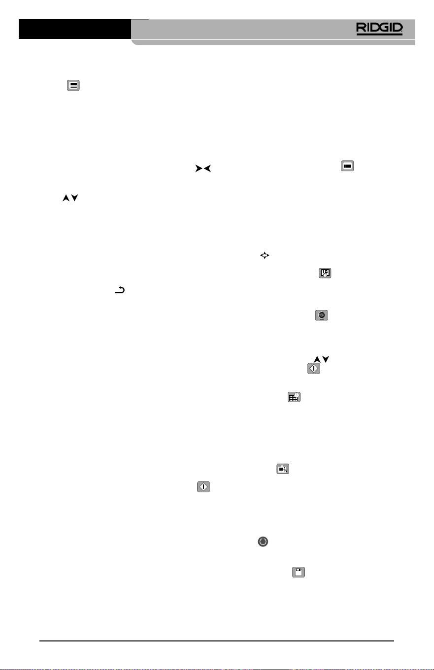
Инспекционная видеокамера micro CA-350
83
Меню
После нажатия в любое время на кнопку
меню
откроется меню. Меню откры‑
вается поверх рабочего экрана с изо‑
бражением от видеокамеры в реальном
времени. Из меню пользователь может
осуществлять переключение в различные
режимы или входить в меню настроек.
С экрана настроек можно выбрать разные
категории настроек (рис. 17). Используя
кнопки со стрелками вправо и влево
переходите от одной категории к другой.
Используя кнопки со стрелками вверх и
вниз
, переходите к позициям меню.
Выбранная категория будет выделена яр‑
кой красной контурной рамкой. После до‑
стижения требуемой настройки нажмите
кнопку "Выбрать", чтобы переключить на‑
стройку к новому выбранному значению.
После внесения изменений они сохраня‑
ются автоматически.
Находясь в режиме меню, можно нажать
кнопку "Возврат"
, чтобы вернуться к
предыдущему экрану или перейти к экра‑
ну реального времени.
Рис. 17 - Экран настроек
Режим воспроизведения
1. После нажатия кнопки "Выбор"
экран реального времени переключит‑
ся в режим воспроизведения. Выберите
фотоизображение Image или видеоизо‑
бражение Video для воспроизведения
требуемого файла. Режим воспроизведе‑
ния обеспечивает интерфейс с сохранен‑
ными в памяти файлами. По умолчанию
будет выбран последний записанный
файл.
2. Во время просмотра изображения поль‑
зователь может циклически переключать
все сохраненные изображения, удалять
изображения и отображать информацию
файла.
3. Во время просмотра видеоизображе‑
ния пользователь может переключаться
между видеоизображениями, включать
режим паузы или повторный запуск вос‑
произведения и удалять файлы. Если
флэш‑карта SD™ не введена, пользователь
может воспроизводить только фото‑ и ви‑
деоизображения из внутренней памяти
прибора.
Удаление файлов
Нажмите кнопку "Меню" из режи‑
ма воспроизведения, чтобы удалить
фото‑ или видеоизображение. Появится
диалоговое окно подтверждения уда‑
ления, которое позволяет пользовате‑
лю удалять ненужные файлы. Активный
значок выделяется красной контурной
рамкой. Навигационные переходы вы‑
полняются с помощью кнопок со стрел‑
ками
.
Отметка времени
Включает или выключает отображение даты
и времени.
Язык сообщений
В меню выберите значок "Язык сообще‑
ний" и нажмите кнопку "Выбрать". Выбери‑
те требуемый язык с помощью кнопок со
стрелками вверх/вниз
, а затем нажми‑
те кнопку "Выбрать"
, чтобы сохранить
настройку языка.
Дата/время
Позволяет выбрать настройку даты или
настройку времени для установки теку‑
щей даты или времени. Выберите формат
даты или времени, чтобы изменить способ
отображения даты/времени.
ТВ‑выход
Выберите режим "NTSC" или "PAL", для требу‑
емого формата видеоизображения на теле‑
визионный выход. Экран прибора погаснет,
и изображение будет выведено на внешний
экран. Чтобы вывести на приборе изобра‑
жение в реальном времени, нажмите кнопку
питания
для выключения этой функции.
Обновить микропрограммное
обеспечение
Выберите функцию обновления микропрог‑
раммного обеспечения "Update Firmware",
чтобы установить в приборе последнюю
версию программного обеспечения. Прог‑
раммное обеспечение необходимо записать
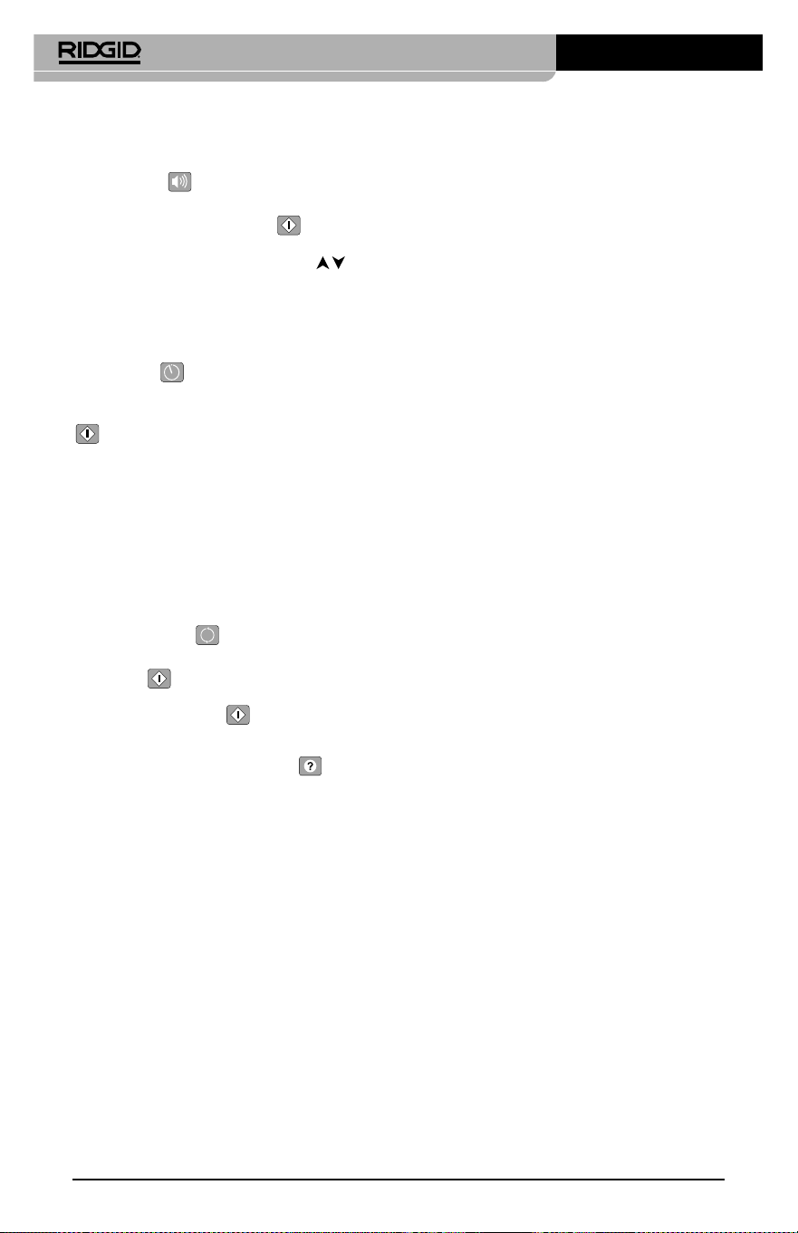
Инспекционная видеокамера micro CA-350
84
на флэш‑карту SD™, а затем вставить карту в
прибор. Обновления размещаются на сайте
RIDGID.com.
Динамик
Выберите в меню значок динамика и на‑
жмите кнопку "Выбрать"
. Выберите
"ВКЛ" ("ON") или "ВЫКЛ" ("OFF") с помощью
кнопки со стрелкой вверх/вниз
, что‑
бы динамик видеокамеры был ВКЛЮЧЕН
("ON") или ВЫКЛЮЧЕН ("OFF") во время
воспроизведения видеоизображения.
Автоматическое выключение
питания
Выберите значок автоматического выклю‑
чения питания и нажмите кнопку "Выбрать"
. Выберите опцию "Отключить", чтобы
ОТКЛЮЧИТЬ ("OFF") функцию автоматиче‑
ского выключения питания. Выберите один
из указанных ниже интервалов бездействия
(5/15/60 минут) для ВЫКЛЮЧЕНИЯ ("OFF") пи‑
тания прибора через 5 минут, 15 минут или
60 минут. При записи или воспроизведении
видеоизображений режим автоматического
выключения питания не активизируется.
Сброс к заводским
настройкам
Выберите значок сброса и нажмите кнопку
"Выбрать" . Подтвердите функцию сброса,
для этого выберите "Да" ("Yes") и нажмите еще
раз кнопку "Выбрать"
после этого прибор
будет сброшен к заводским настройкам.
Сведения о программе
Выберите функцию "Сведения о програм‑
ме", чтобы отобразить версию микропро‑
граммного обеспечения прибора micro
CA‑350 и вывести на экран информацию
об авторском праве на эту программу.
Перенос изображений в
компьютер
С помощью USB‑кабеля, подключите micro
CA‑350 с включенным питанием к компью‑
теру. На дисплее прибора micro CA‑350 по‑
явится экран связи по USB‑кабелю. Внутрен‑
няя память прибора и память флэш‑карты
SD™ (если таковая имеется) появятся на
компьютере как отдельные накопители и
будут доступны как стандартные устройства
USB памяти. Можно выполнять операции
копирования и удаления с компьютера.
Подключение к телевизору
Инспекционную видеокамеру micro CA‑350
можно подключить к телевизору или к друго‑
му видеомонитору для удаленного просмотра
изображения или видеозаписи с помощью
входящего в комплект прибора RCA‑кабеля.
Откройте крышку гнезд с правой сторо‑
ны прибора (рис. 3
). Вставьте RCA‑кабель
в гнездо выхода на телевизор TV‑Out.
Вставьте другой конец кабеля в гнездо
видеовхода телевизора или видеомонито‑
ра. Проверьте правильность установки
видеоформата вывода (NTSC или PAL).
Возможно, для просмотра изображения
на телевизоре или видеомониторе при‑
дется включить соответствующий вход ви‑
деосигнала. С помощью меню, выберите
соответствующий формат вывода изобра‑
жения на телевизор через ТВ‑выход.
Использование видеокамеры
с инспекционным
оборудованием SeeSnake
®
Инспекционную видеокамеру micro CA‑350
также можно использовать с различным
инспекционным оборудованием SeeSnake,
которое специально спроектировано для
применения с инспекционными системами
microReel, microDrain™ и nanoReel. При ис‑
пользовании видеокамеры с этими вида‑
ми оборудования она сохраняет все свои
функциональные возможности, описанные
в настоящем руководстве. Инспекционную
видеокамеру micro CA‑350 также можно ис‑
пользовать с другим инспекционным обо‑
рудованием SeeSnake только для просмо‑
тра и записи изображений.
Для использования видеокамеры с инспек‑
ционным оборудованием SeeSnake необ‑
ходимо снять головку формирования изо‑
бражения и любые удлинительные кабели.
Сведения о правильном подключении и
применении систем microReel, microDrain,
nanoReel и другого аналогичного оборудо‑
вания см. в руководстве по эксплуатации. В
случае применения другого инспекцион‑
ного оборудования SeeSnake (обычно ка‑
тушки и видеомонитора) для подключения
инспекционной видеокамеры micro CA‑350
к порту видеовыхода на инспекционном
оборудовании SeeSnake требуется исполь‑
зовать переходник. При таком подключе‑
нии инспекционная видеокамера micro
CA‑350 отобразит на экране сигнал с видео‑
камеры, который можно записать в память.
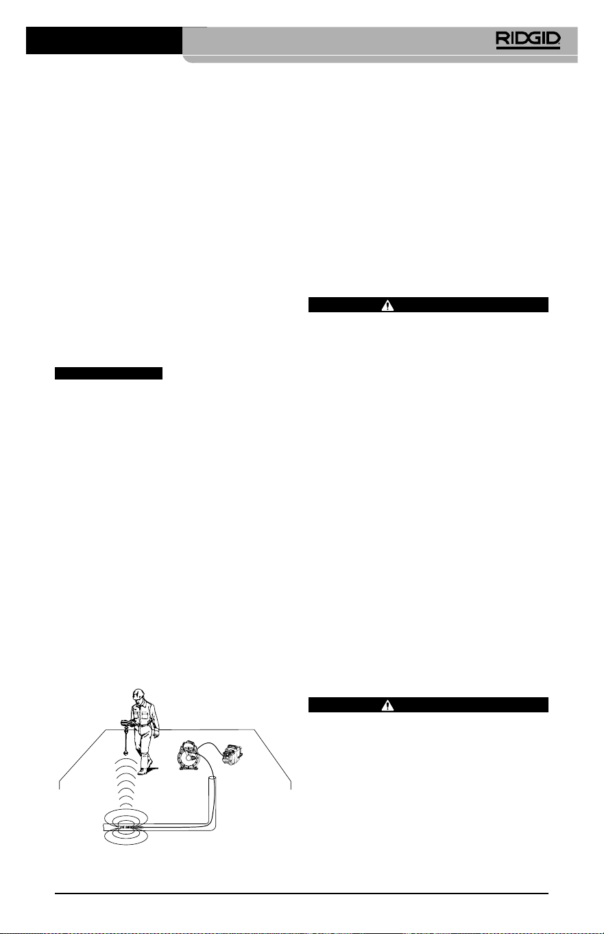
Инспекционная видеокамера micro CA-350
85
При подключении инспекционного обору‑
дования SeeSnake (microReel, microDrain™
или nano‑Reel) следует совместить модуль
взаимного соединения, подключенный к
вашей катушке, с кабельным разъемом на
инспекционной видеокамере micro CA‑350,
вставить его прямо во внутрь и располо‑
жить под прямым углом. (См. рис. 18)
Рис. 18 - Вилка разъема видеокамеры
подключена
ПРЕДУПРЕЖДЕНИЕ
Во избежание повреж‑
дений не следует перекручивать вилку
разъема.
Точное определение местонахождения
зонда
При работе с зондом (линейным излуча‑
телем), управлять им можно двумя спосо‑
бами. Если катушка оборудована ключом
зонда, его можно использовать для ВКЛЮ‑
ЧЕНИЯ ("ON") и ВЫКЛЮЧЕНИЯ ("OFF") зон‑
да. В ином случае зонд ВКЛЮЧАЮТ ("ON")
путем уменьшения яркости светодиода до
нуля. После обнаружения местоположе‑
ния зонда можно восстановить обычный
уровень яркости светодиода, чтобы про‑
должить инспекцию.
Для функций поиска зонда в осматри‑
ваемом канализационном трубопро‑
воде можно использовать такие ло‑
каторы RIDGID, как SR‑20, SR‑60, Scout
или NaviTrack® II, настроенные на
частоту 512 Гц.
Рис. 19 - Определение местонахождения
зонда катушки
Для поиска зонда ВКЛЮЧИТЕ ("ON") лока‑
тор и переведите его в режим поиска зон‑
да. Сканируйте в направлении возможно‑
го нахождения зонда, пока локатор его не
обнаружит. Когда зонд будет обнаружен,
используйте обнуление показания локато‑
ра для нахождения более точного место‑
положения. Более подробные инструкции
по обнаружению зонда можно найти в ру‑
ководстве по эксплуатации используемой
вами модели локатора.
Техническое
обслуживание
ВНИМАНИЕ
Перед чисткой выньте батарею.
• После использования всегда очищайте
головку формирования изображения
и кабель слабым раствором мыла или
моющего средства.
• Аккуратно без нажима протирайте
экран дисплея чистой сухой тряпкой.
Не трите слишком сильно.
• Разъемные соединения кабелей следу‑
ет очищать только тампонами, смочен‑
ными спиртом.
• Протирайте переносной блок дисплея
чистой сухой тряпкой.
Функция сброса
Если прибор перестает работать и не дает
ответных реакций, нажмите кнопку "Сброс"
(под левой боковой крышкой гнезд прибо-
ра – см. рис. 4). После перезапуска прибор
может восстановить свою нормальную
работу.
Дополнительные
принадлежности
ВНИМАНИЕ
Для снижения риска серьезных травм
используйте только те принадлежности,
которые специально разработаны и ре‑
комендованы к использованию с инспек‑
ционной видеокамерой micro CA‑350
RIDGID. Они перечислены ниже. Другие
принадлежности, подходящие для ра‑
боты с другими приборами, могут быть
опасны при использовании с инспекци‑
онной видеокамерой micro CA‑350.
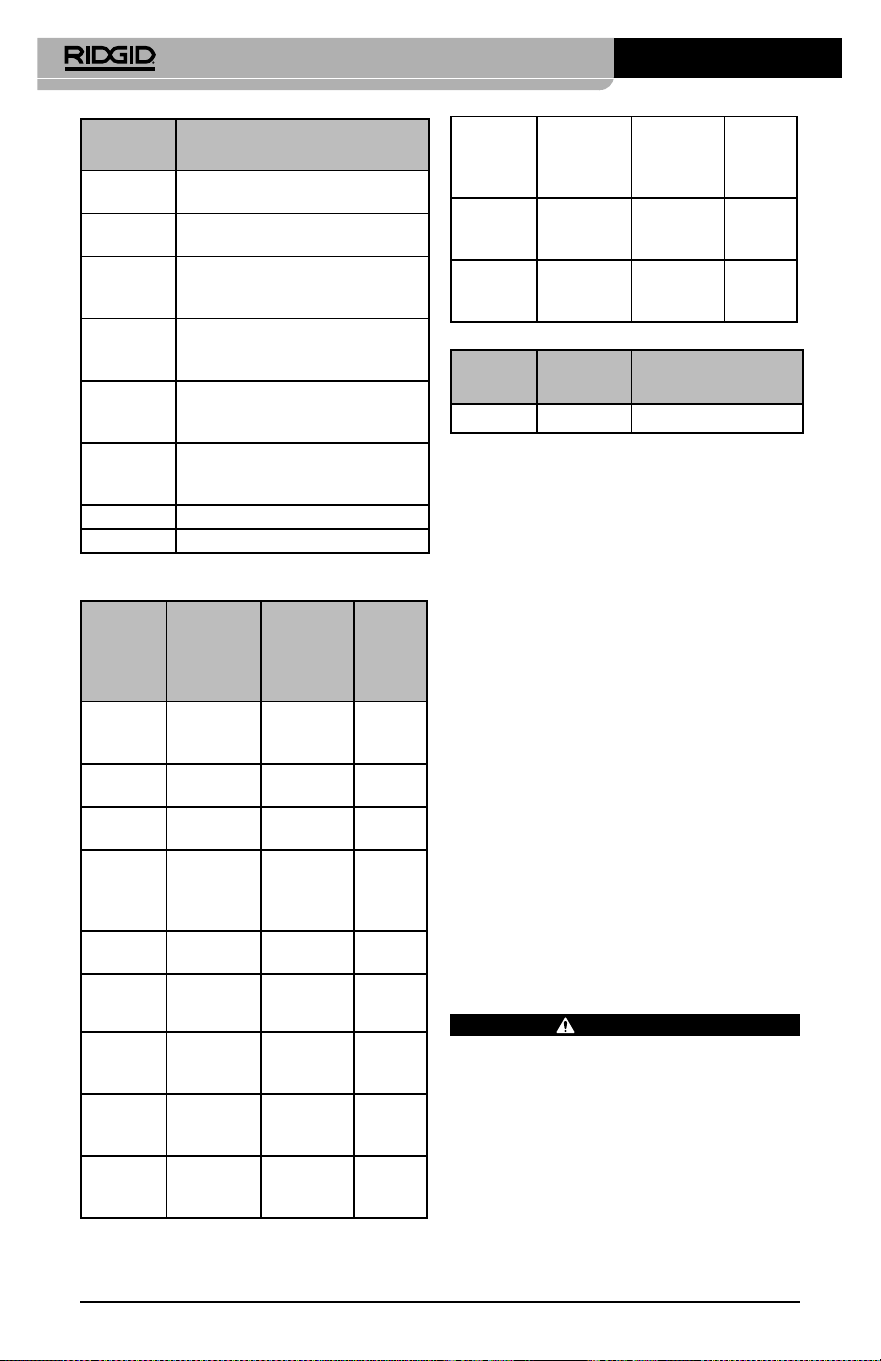
Инспекционная видеокамера micro CA-350
86
№ по
каталогу Описание
37108 Удлинительный кабель 3 фута
(90 см)
37113 Удлинительный кабель
6футов (180 см)
37103 Головка формирования
изображения и 90 см кабель‑
17 мм
37098 Головка формирования
изображения, длина 1 м, диам.
6 мм
37093 Головка формирования
изображения, длина 4 м, диам.
6 мм
37123 Комплект дополнительных
принадлежностей (крючок,
магнит и зеркало), 17 мм
36758 Адаптер переменного тока
40623 Наушники с микрофоном
№ по
каталогу
Регион
Тип
штеп
-
сель-
ной
вилки
55193
Зарядное
устройство
США,
Канада,
Мексика
A
55198
Зарядное
устройство
Европа
C
55203
Зарядное
устройство
Китай
A
55208
Зарядное
устройство
Австра‑
лия и
Латинская
Америка
I
55213
Зарядное
устройство
Япония
A
55218
Зарядное
устройство
Велико‑
британия
G
44798
Шнур
зарядного
устройства
Северная
Америка
A
44808
Шнур
зарядного
устройства
Европа
C
44803
Шнур
зарядного
устройства
Китай
A
RBC-121 Зарядные устройства и шнуры
44813
Шнур
зарядного
устройства
Австра‑
лия и
Латинская
Америка
I
44818
Шнур
зарядного
устройства
Япония A
44828
Шнур
зарядного
устройства
Велико‑
британия
G
№ по
каталогу
Модель Емкость
55183 RB‑1225 12 В 2,5 А·ч
Аккумуляторы
Все перечисленные аккумуляторы предназначены для
работы с зарядным устройством с номером по каталогу
RBC‑121.
Чтобы получить полный перечень обору‑
дования RIDGID, подходящего для этого
прибора, посмотрите каталог Ridge Tool
на сайте RIDGID.com или позвоните в тех‑
ническую службу Ridge Tool по телефону
(800) 519‑3456.
Хранение прибора
Инспекционную видеокамеру RIDGID micro
CA‑350 следует хранить в сухом безопас‑
ном месте при температуре от ‑4°F (‑20°C) до
140°F (60°C) и относительной влажности от
15% до 85%.
Прибор надлежит хранить в запираемом
помещении, недоступном для детей и лю‑
дей, которые не знакомы с инспекцион‑
ной видеокамерой micro CA‑350.
Перед транспортировкой или постанов‑
кой на хранение извлеките аккумулятор
из прибора.
Обслуживание и ремонт
ВНИМАНИЕ
Ненадлежащее техобслуживание или
ремонт могут стать причиной небезопас‑
ной работы инспекционной видеокаме‑
ры micro CA‑350 RIDGID.
Техническое обслуживание и ремонт ин‑
спекционной видеокамеры micro CA‑350
следует производить в независимых ав‑
торизованных сервисных центрах RIDGID.

Инспекционная видеокамера micro CA-350
87
Для получения информации о ближайшем
независимом сервис‑центре RIDGID, об‑
служивании или ремонте:
• Обратитесь к местному дистрибьюто‑
ру RIDGID.
• Чтобы найти контактный телефон мест‑
ного дистрибьютора RIDGID, войдите на
сайт RIDGID.com.
• Обратитесь в Отдел технического
обслуживания RIDGID по адресу
rtc[email protected], в США и
Канаде вы также можете позвонить по
телефону (800) 519‑3456.
Утилизация
Детали инспекционной видеокамеры micro
CA‑350 RIDGID содержат ценные материа‑
лы и могут быть подвергнуты повторной
переработке. В своем регионе вы можете
найти компании, специализирующиеся на
утилизации. Утилизируйте компоненты в
соответствии со всеми действующими пра‑
вилами. Узнайте дополнительную инфор‑
мацию в местной организации по утилиза‑
ции отходов.
Для стран ЕС: Не утилизируйте
электрооборудование вместе с
бытовыми отходами!
В соответствии с Директивой Евро‑
союза 2012/19/EU по утилизации
электрического и электронного
оборудования, электрическое оборудование,
непригодное для дальнейшего использова‑
ния, следует собирать отдельно и утилизи‑
ровать безопасным для окружающей среды
способом.

Инспекционная видеокамера micro CA-350
88
ПРИЗНАК
НЕИСПРАВНОСТИ
ВОЗМОЖНАЯ
ПРИЧИНА
РЕШЕНИЕ
Экран ВКЛЮЧАЕТСЯ, но не
показывает изображения.
Неплотные кабельные со‑
единения.
Проверьте кабельные соедине‑
ния, при необходимости очисти‑
те. Подсоедините еще раз.
Неисправна головка форми‑
рования изображения.
Замените головку формирования
изображения.
Головка формирования изо‑
бражения покрыта мусором.
Осмотрите головку формирова‑
ния изображения, чтобы убедить‑
ся, что она не покрыта мусором.
Светодиоды на головке фор-
мирования изображения сла-
бо светят при максимальной
яркости, экран переключает-
ся между черным и белым,
цветной эк ран ГАСНЕТ по
истечении короткого проме-
жутка времени.
Батарея разряжена. Замените разряженную батарею
на заряженную.
Прибор не ВКЛЮЧАЕТСЯ. Батарея полностью разря‑
дилась.
Замените разряженную батарею
на заряженную.
Необходимо перезапустить
прибор.
Перезапустить прибор. См. раздел
"Техническое обслуживание".
Поиск и устранение
неисправностей

micro CA-350-inspectiecamera
89
Manufacturer:
RIDGE TOOL COMPANY
400 Clark Street
Elyria, Ohio 44035-6001
U.S.A.
Authorized Representative:
RIDGE TOOL EUROPE N.V.
Schurhovenveld 4820
3800 Sint-Truiden
Belgium
CE Conformity
This instrument complies with the European Council Electromagnetic
Compatibility Directive 2004/108/EC using the following standards:
EN 61326-1:2006, EN 61326-2-1:2006.
Conformité CE
Cet instrument est conforme à la Directive du Conseil européen
relative à la compatibilité électromagnétique 2004/108/CE sur la base
des normes suivantes : EN 61326-1:2006, EN 61326-2-1:2006.
Conformidad CE
Este instrumento cumple con la Directiva de Compatibilidad
Electromagnética 2004/108/CE del Consejo Europeo mediante las
siguientes normas: EN 61326-1:2006, EN 61326-2-1:2006.
CE Uygunluğu
Bu cihaz, aşağıdaki standartları kullanan Avrupa Konseyi Elekt-
romanyetik Uyumluluk Direktifi 2004/108/EC ile uyumludur:
EN61326-1:2006, EN 61326-2-1:2006.
Соответствие требованиям Евросоюза (CE)
Настоящий прибор соответствует требованиям по эле ктро маг-
нитной совместимости 2004/108/EC Директи вы Европейского
Союза с применением следующих стандартов: EN 61326-1:2006,
EN 61326-2-1:2006.
What is covered
RIDGID
®
tools are warranted to be free of defects in workmanship and material.
How long coverage lasts
This warranty lasts for the lifetime of the RIDGID
®
tool. Warranty coverage ends when the
product becomes unusable for reasons other than defects in workmanship or material.
How you can get service
To obtain the benefit of this warranty, deliver via prepaid transportation the complete prod-
uct to RIDGE TOOL COMPANY, Elyria, Ohio, or any authorized RIDGID
®
INDEPENDENT
SERVICE CENTER. Pipe wrenches and other hand tools should be returned to the place of pur-
chase.
What we will do to correct problems
Warranted products will be repaired or replaced, at RIDGE TOOL’S option, and returned at no
charge; or, if after three attempts to repair or replace during the warranty period the product
is still defective, you can elect to receive a full refund of your purchase price.
What is not covered
Failures due to misuse, abuse or normal wear and tear are not covered by this warranty. RIDGE
TOOL shall not be responsible for any incidental or consequential damages.
How local law relates to the warranty
Some states do not allow the exclusion or limitation of incidental or consequential damages,
so the above limitation or exclusion may not apply to you. This warranty gives you specific
rights, and you may also have other rights, which vary, from state to state, province to
province, or country to country.
No other express warranty applies
This FULL LIFETIME WARRANTY is the sole and exclusive warranty for RIDGID
®
prod-
ucts. No employee, agent, dealer, or other person is authorized to alter this warranty or make
any other warranty on behalf of the RIDGE TOOL COMPANY.
Qué cubre
Las herramientas RIDGID
®
están garantizadas contra defectos de la mano de obra y de los
materiales empleados en su fabricación.
Duración de la cobertura
Esta garantía cubre a la herramienta RIDGID
®
durante toda su vida útil. La cobertura de la
garantía caduca cuando el producto se torna inservible por razones distintas a las de defec-
tos en la mano de obra o en los materiales.
Cómo obtener servicio
Para obtener los beneficios de esta garantía, envíe mediante porte pagado, la totalidad del pro-
ducto a RIDGE TOOL COMPANY, en Elyria, Ohio, o a cualquier Servicentro Independiente
RIDGID. Las llaves para tubos y demás herramientas de mano deben devolverse a la tienda
donde se adquirieron.
Lo que hacemos para corregir el problema
El producto bajo garantía será reparado o reemplazado por otro, a discreción de RIDGE TOOL,
y devuelto sin costo; o, si aún resulta defectuoso después de haber sido reparado o sustitu-
ido tres veces durante el período de su garantía, Ud. puede optar por recibir un reembolso
por el valor total de su compra.
Lo que no está cubierto
Esta garantía no cubre fallas debido al mal uso, abuso o desgaste normal. RIDGE TOOL no
se hace responsable de daño incidental o consiguiente alguno.
Relación entre la garantía y las leyes locales
Algunos estados de los EE.UU. no permiten la exclusión o restricción referente a daños in-
cidentales o consiguientes. Por lo tanto, puede que la limitación o restricción mencionada
anteriormente no rija para Ud. Esta garantía le otorga derechos específicos, y puede que,
además, Ud tenga otros derechos, los cuales varían de estado a estado, provincia a provin-
cia o país a país.
No rige ninguna otra garantía expresa
Esta GARANTIA VITALICIA es la única y exclusiva garantía para los productos RIDGID
®
.
Ningún empleado, agente, distribuidor u otra persona está autorizado para modificar esta
garantía u ofrecer cualquier otra garantía en nombre de RIDGE TOOL COMPANY.
Ce qui est couvert
Les outils RIDGID
®
sont garantis contre tous vices de matériaux et de main d’oeuvre.
Durée de couverture
Cette garantie est applicable durant la vie entière de l’outil RIDGID
®
. La couverture cesse dès lors
que le produit devient inutilisable pour raisons autres que des vices de matériaux ou de main
d’oeuvre.
Pour invoquer la garantie
Pour toutes réparations au titre de la garantie, il convient d’expédier le produit complet en port
payé à la RIDGE TOOL COMPANY, Elyria, Ohio, ou bien le remettre à un réparateur RIDGID
®
agréé. Les clés à pipe et autres outils à main doivent être ramenés au lieu d’achat.
Ce que nous ferons pour résoudre le problème
Les produits sous garantie seront à la discrétion de RIDGE TOOL, soit réparés ou remplacés,
puis réexpédiés gratuitement ; ou si, après trois tentatives de réparation ou de remplacement
durant la période de validité de la garantie le produit s’avère toujours défectueux, vous aurez
l’option de demander le remboursement intégral de son prix d’achat.
Ce qui n’est pas couvert
Les défaillances dues au mauvais emploi, à l’abus ou à l’usure normale ne sont pas couvertes
par cette garantie. RIDGE TOOL ne sera tenue responsable d’aucuns dommages directs ou in-
directs.
L’influence de la législation locale sur la garantie
Puisque certaines législations locales interdisent l’exclusion des dommages directs ou indirects,
il se peut que la limitation ou exclusion ci-dessus ne vous soit pas applicable. Cette garantie vous
donne des droits spécifiques qui peuvent être éventuellement complétés par d’autres droits
prévus par votre législation locale.
Il n’existe aucune autre garantie expresse
Cette GARANTIE PERPETUELLE INTEGRALE est la seule et unique garantie couvrant les pro-
duits RIDGID
®
. Aucun employé, agent, distributeur ou tiers n’est autorisé à modifier cette
garantie ou à offrir une garantie supplémentaire au nom de la RIDGE TOOL COMPANY.
Printed 6/18 999-995-087.10
EC42736 REV. C
©2016, 2018 RIDGID, Inc.
The Emerson logo and RIDGID logo are registered trademarks of Emerson Electric Co. or RIDGID, Inc. in the U.S. and other countries.
All other trademarks belong to their respective holders.
Against Material Defects
& Workmanship
FULL LIFETIME
WARRANTY
Ridge Tool Company
400 Clark Street
Elyria, Ohio 44035-6001
U.S.A.
Full lifetime warranty (garantie légale étendue à la durée de vie du produit,
voir conditions de garantie / legal warranty extended to the product lifecyle,
see warranty conditions)
Parts are available online at Store.RIDGID.com