INSTRUCTION MANUAL
S3570, Rev A
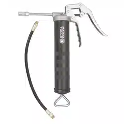
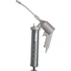
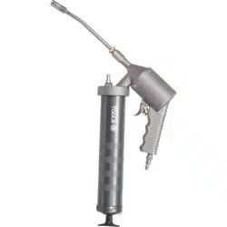
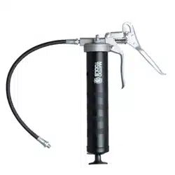
Lever Grease Guns
Heavy Duty
Top of the line grease gun for heavy
industrial applications.
Built Tough
• Barrel with 0.049" (1.2 mm) wall
thickness.
• Heavy duty follower spring.
• High tolerance CNC machined,
aluminium die cast head.
• Rolled threads for quick & easy
re-loading.
Variable Stroke
Convenient greasing even in tight spaces
with limited movement of handle.
Available in 2 choices
a. 6" (150 mm) steel extension & coupler.
b. 12" (300 mm) × 0.33" (8.5 mm) flexible
hose & coupler.
G4-HD
G18-HDG10-HD
G1-HD
CAT
NR.
CAT
NR.
CARTRIDGE CAPACITY BULK CAPACITY THREADS
(OZ) (GMS) (CM
3
)
6" (150MM)
STEEL EXTENSION & COUPLER
12" (300MM)
FLEXIBLE HOSE & COUPLER
G1R/HD/B G1F/HD/B 14 400 500 1/8" BSPT
G1R/HD/M G1F/HD/M 14 400 500 M10 × 1
G1R/HD/N G1F/HD/N 14 400 500 1/8" NPT
G4R/HD/B G4F/HD/B - 450 650 1/8" BSPT
G10R/HD/B G10F/HD/B 14 400 750 1/8" BSPT
G10R/HD/M G10F/HD/M 14 400 750 M10 × 1
G10R/HD/N G10F/HD/N 14 400 750 1/8" NPT
G18R/HD/M G18F/HD/M 21 600 700 M10 × 1
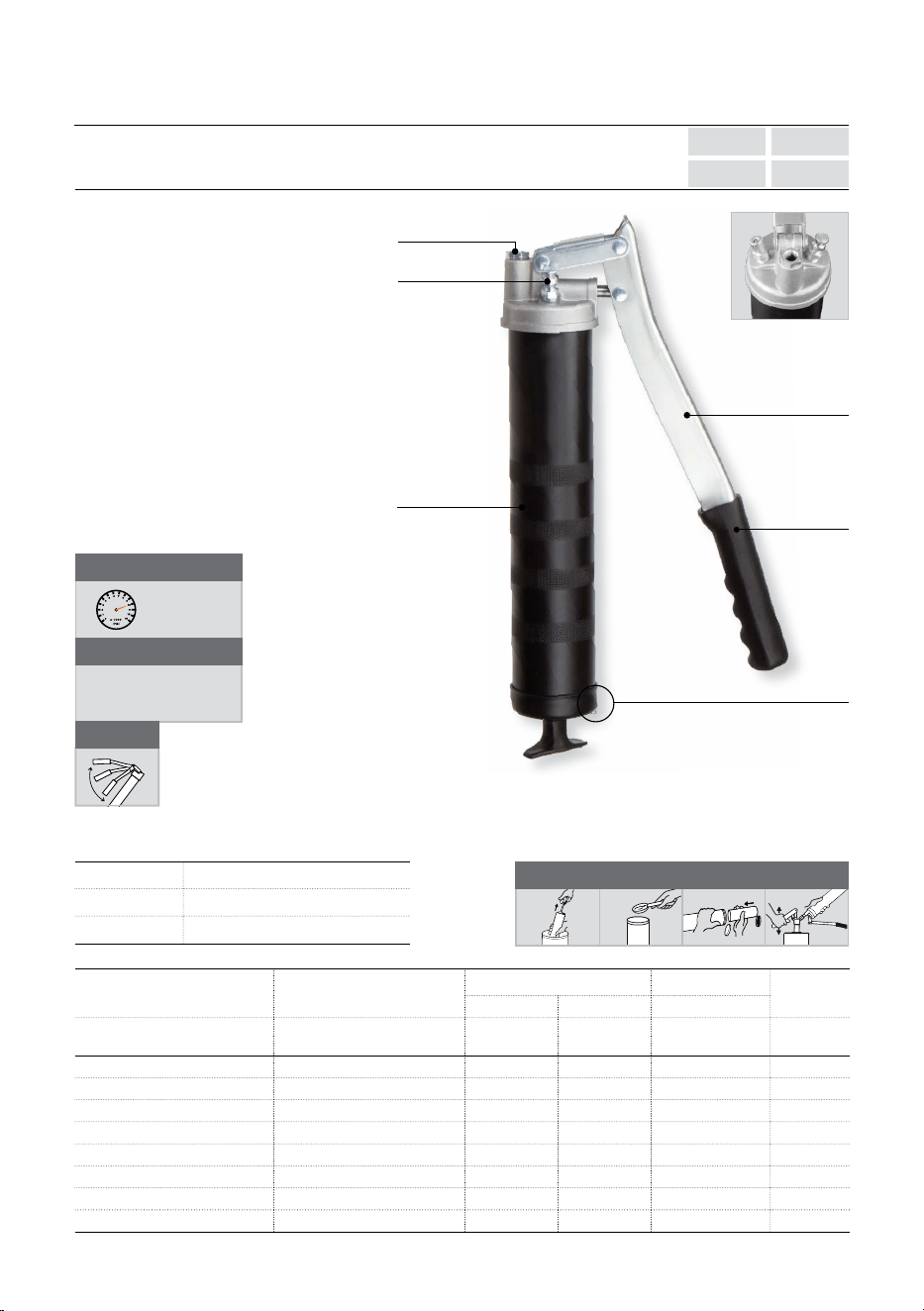
Zinc plated
lever handle
Ergonomic
rubber grip
Non slip
textured
powder coated
finish
Lock Lever: Locks
plunger rod at
any position
Air release
valve
Top Port
SUCTION
FILL
BULK
FILL
CARTRIDGE
LOADING
FILLER PUMP
LOADING
Aluminium die cast
head with bulk loader
and air bleeder valve
HANDLE STYLE Lever
COUPLER Professional 4-jaw with ball check
THREAD 1/8" BSPT / M10×1 / 1/8" NPT
SPECIFICATIONS
DEVELOPS
UPTO
10,000 PSI
(690 BAR)
DELIVERS
UPTO
1 GM / STROKE
(1 OZ. / 28 STROKES)
VARIABLE
STROKE

2
SAFETY INFORMATION
• Follow workshop Health & Safety rules,
regulations and conditions when using the
grease gun.
• During their period of use, accessories must
be checked for wear, cracks and other
damage, replace any damaged or worn
parts.
• Use genuine parts only. Unauthorized parts
may be dangerous and will void the warranty.
• Wear approved safety gloves and eye and
ear protection.
• Keep the gun clean and in good working
order for best and safest peormance.
WARNING!
• DO NOT use the gun for a task it is not
designed to peorm.
• DO NOT drop, throw or abuse the gun.
• DO NOT carry the gun by the extension.
• Grease is delivered at high pressure. DO NOT
point the grease gun outlet at yourself or
others.
• DO NOT use gun if damaged or thought to be
faulty. Contact your local service agent.
PACKAGE CONTENT
DESCRIPTION QUANTITY
Lever grease gun Heavy duty 1
Extension (Rigid steel / Flexible hose) with
grease coupler
1
O.I.P.M. 1
TOOLS NEEDED
• 14 mm spanner / 9/16” spanner
BEFORE INSTALLATION
• Use only original accessories compliant with
these guns.
• Keep hose away from heat, oil and sharp
edges. Check hose for wear and make sure
that all connections are secure.
• Excess pressure at the greasing point can
damage the grease nipple, bearings, and
even the machine.
WARNING!
• Defective accessories can lead to personal
injury and material damage.
INSTALLATION
(Refer “EXPLODED VIEW”)
Setting up the grease gun head
Note: Use P.T.F.E. tape while connecting extension
(4) to the grease gun head (2) and grease coupler
(3) to the extension (4).
1. Connect the extension (4) to the outlet of
grease gun head (2).
2. Thread tighten the grease coupler (3) to other
end of extension (4).
3. All connections should be tight.
CAUTION!
Grease or empty cartridge in barrel is under
pressure from the internal spring, Be alert when
removing head of the barrel.
Loading the grease gun
4. Remove any cartridge in the grease gun
barrel (1) prior to refilling.
5. First pull out the plunger handle (6) to its
maximum distance and lock it in place.
6. Remove the grease gun head (2) by turning it
counter clockwise.
7. Remove any empty cartridge.
Always follow the steps listed above in preparing
to load grease gun before proceeding to the
appropriate loading method.
There are 4 ways to load this grease gun:
• Cartridge loading
• Bulk fill
• Suction fill
• Filler pump loading
Cartridge loading
1. Fully draw back the plunger handle (6) and
lock it in place.
2. Remove the grease gun head (2) from the
grease gun barrel (1) by turning it counter
clockwise.
3. Insert the open end of the cartridge into the
grease gun barrel (1) and push it all the way in.
4. Remove the seal or pull tab end from the
cartridge.
5. Reassemble the grease gun head (2) to the
grease gun barrel (1) by turning it clockwise.
Bulk fill
1. Fully draw back the plunger handle (6) and
lock it in place.
2. Remove the grease gun head (2) from the
grease gun barrel (1) by turning it counter
clockwise.
3. Fill the grease gun barrel (1) with grease using
a spatula.
4. Reassemble the grease gun head (2) to the
grease gun barrel (1) by turning it clockwise
Suction fill
1. Remove the grease gun head (2) from the
grease gun barrel (1) by turning it counter
clockwise.
2. Submerge the open end of the grease gun
barrel (1) into grease bucket by approximately
2” and fully draw back the plunger handle (6)
and lock it in place.
3. Reassemble the grease gun head (2) to the
grease gun barrel (1) by turning it clockwise.
3
Filler Pump loading
1. Fully draw back the plunger handle (6) and
lock it in place.
2. Insert bulk loader valve (9) into the filler pump
socket.
3. Operate the filler pump to fill the grease gun
barrel (1).
4. Disconnect the grease gun from the filler
pump.
CAUTION!
• Do not apply excessive torque or over-tighten
the grease gun head as this will apply undue
stress to the die cast outlet and may cause it
to fracture.
Removing trapped air
Aer filling grease gun, trapped air should be
removed by following the below steps.
General procedure
1. While screwing back the grease gun head
(2) onto the grease gun barrel (1), make sure
to tighten it only half way, leaving 2-3 turns
before the head is fully tight.
2. Release the plunger handle (6) and push
down on it.
3. Force the plunger rod (7) in & out a few times
in order to compress the grease & force out
trapped air in the grease from the loose
connection between the grease gun head (2)
& grease gun barrel (1)
4. Start operating the grease gun lever (5) till
grease starts flowing out continuously. At first
discharge of grease, there may be some air
bubble but will be followed by continuous flow
of grease. If the grease is still accompanied
with air bubble, repeat the above steps again.
5. Once all the air bubbles are removed and
grease starts flowing out continuously, fully
tighten the grease gun head (2) onto the
grease gun barrel (1)
6. The grease gun is now ready to use.
Procedure for grease gun with air release valve
1. Aer filling grease gun barrel (1) with grease
by any of the above methods, reassemble
the gun.
2. Tap the manual air release valve (8) to release
the trapped air.
3. Move the plunger rod (7) forward and
backward to remove any trapped air pockets.
4. Tap the manual air release valve (8) again to
release the trapped air.
5. The grease gun is now ready to use.
OPERATING INSTRUCTIONS
(Refer “EXPLODED VIEW”)
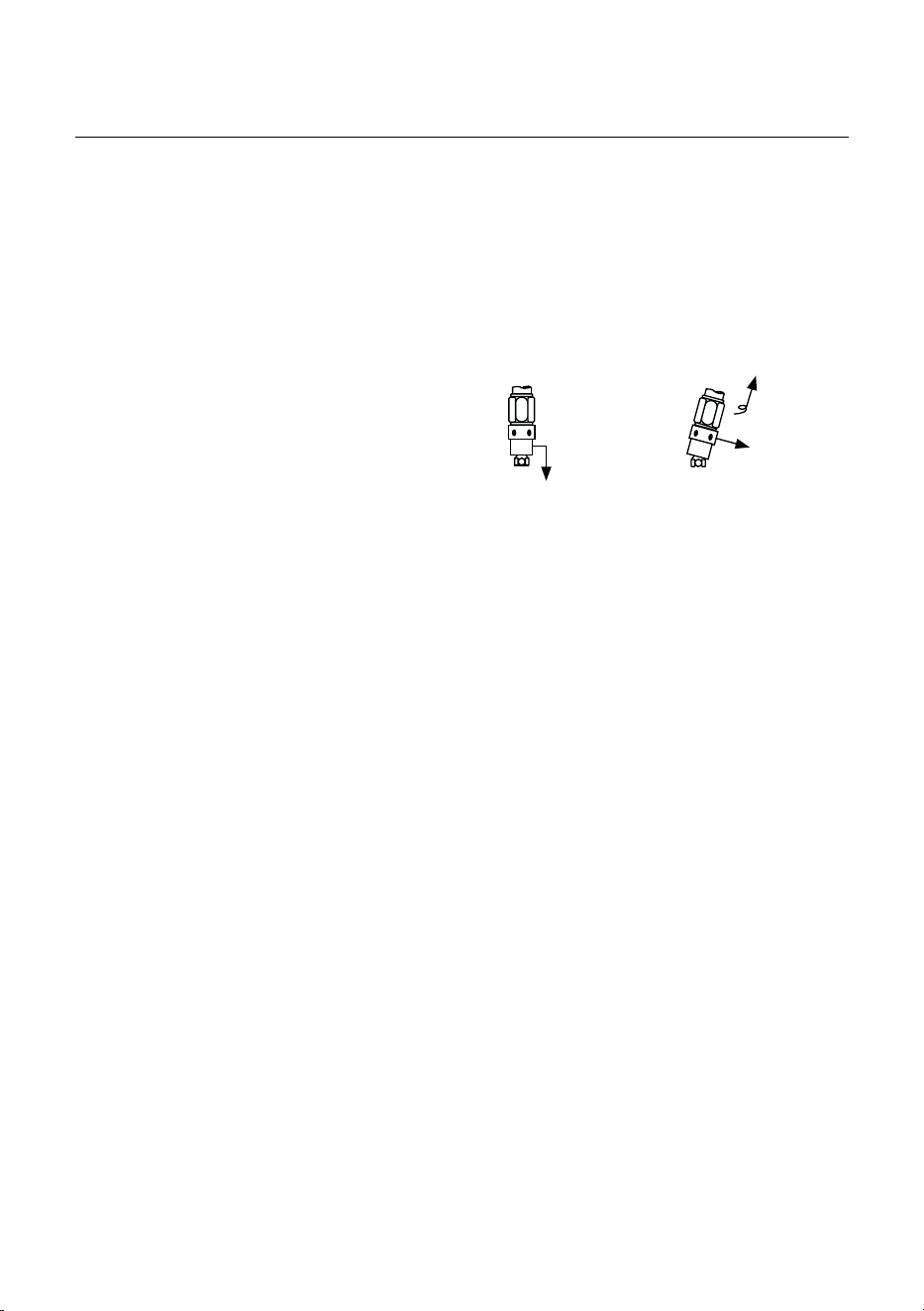
1. The grease coupler (3) provided at the end of
the extension (4) has a jaw type construction.
The coupler jaws will snap on to a grease
fitting and maintain a tight fit.
2. When connecting the grease coupler (3) to
the grease fitting, press the grease coupler
(3) straight onto the grease fitting to form a
snug fit.
3. Start operating the lever (5) with the grease
coupler (3) as aligned to the grease fitting as
possible.
4. Once greasing is completed, slightly tilt the
grease coupler (3), twist and pull back.
5. The tilt and twist action will allow easy
removal of the grease coupler (3) from the
grease fitting.
To engage push
straight on the
grease nipple
To remove Tilt,
Twist & Pull
WARNING!
• Do not exceed the maximum working pressure
of 10,000 PSI.
MAINTENANCE
(Refer “EXPLODED VIEW”)
• Grease gun and extension (4) should be kept
clean and checked for damage before each
use.
4
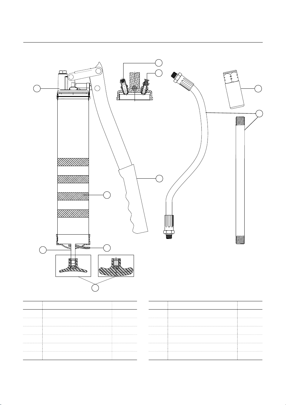
EXPLODED VIEW
REF NO. PARTS DESCRIPTION QUANTITY
1 Grease gun barrel 1
2 Grease gun head 1
3 Grease coupler 1
4 Extension (Rigid steel/Flexible hose) 1
5 Lever 1
6 Plunger handle 1
PARTS LIST
REF NO. PARTS DESCRIPTION QUANTITY
6 (a) Type-A*
6 (b) Type-B**
7 Plunger rod 1
8 Air release valve 1
9 Bulk loader valve 1
10 Lock Lever 1
Type-A Type-B
1
10
2
7
3
4
5
6
8
9
*For G1 versions only
**For G4, G10 & G18 versions

5
PROBLEM POSSIBLE CAUSE CORRECTIVE ACTION
Grease gun pumps little or no grease. Barrel not completely tightened. Tighten the barrel completely
Air Pockets are trapped in grease Remove air pocket by referring to “Removing
trapped air” section
Blocked grease gun extension Remove the extension and operate the grease
gun. If the gun dispenses grease then the gun is
fine. Clean or replace the extension
Grease too thick or cold Store grease gun and grease away from
extreme cold or use thinner grease
Excessive grease leaking past the follower Follower is damaged Replace the grease gun
If the gun still doesn't operate Contact nearest authorized service dealer
TROUBLESHOOTING
DISPOSAL
The components or the used products must be given to companies that specialize in the disposal and
recycling of industrial waste.

NOTE

NOTE

NOTE