
OWNER’S MANUAL
INSTALLATION AND
OPERATION INSTRUCTIONS
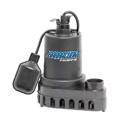
CAST IRON SUBMERSIBLE SUMP PUMP
MODEL: BAS33V-1-10
SKU#: 691-3312

2
If for any reason you have questions concerning your new Barracuda Pump, call us toll free at
1-844-251-7445.
Carefully read and understand all of the warnings and installation instructions in this manual. Failure
to follow these instructions could lead to serious bodily injury and/or property damage. Retain these
instructions for future reference. This pump has been manufactured with your needs in mind. Properly
installed in the right application, your new Barracuda Pump will give you years of carefree performance.
Do not pump ammable or explosive liquids such as oil, gasoline, kerosene, ethanol, etc. Do not use
in the presence of ammable or explosive vapors. Using this pump with or near ammable liquids
can cause explosion or re, resulting in serious personal injury and/or property damage.
Always disconnect the pump from its power source before installing, inspecting, maintaining, or repairing.
Do not stand in water when the pump is connected.
Do not touch the pump while it is operating, as the pump may be HOT and can cause serious burns.
Do not disassemble the motor housing. The motor has NO repairable internal parts, and disassembling may
cause oil leakage or dangerous electrical wiring issues and will void warranty.
Never touch any electrical device, including this pump, when it is touching water, in water, or even in a moist
environment. Always unplug (disconnect the electricity) when working on or installing the unit.
RISK OF ELECTRICAL SHOCK. This pump is supplied with a grounding conductor and grounding-type
attachment plug. To reduce the risk of electrical shock, be certain that it is connected only to a properly
grounded, grounding-type receptacle.
Do not use the power cord or discharge hose to carry or handle the pump. Doing so may cause damage to
the power cord or discharge hose. Use the carrying ring supplied with the pump.
Follow all electrical and safety codes, particularly the National Electrical Code (NEC) and in the workplace,
the Occupational Safety and Health Act (OSHA).
This unit is designed only for use on 115 volts (single phase), 60 Hz, and is equipped with an approved
3-conductor cord and 3-prong grounded plug. DO NOT REMOVE THE GROUND PIN UNDER ANY
CIRCUMSTANCES. The 3-prong plug must be directly inserted into a properly installed and grounded
3-prong, grounding-type receptacle. Do not use this pump with a 2-prong wall outlet. Replace the 2-prong
outlet with a properly grounded 3-prong receptacle (a GFCI outlet) installed in accordance with the National
Electrical Code and local codes and ordinances. All wiring should be performed by a qualied electrician.
WARNING
WARNING
WARNING
WARNING
NOTICE
DANGER
3
For safety, the pump motor has an automatic resetting thermal protector that automatically
will turn off the pump if it becomes too hot. Overuse of this feature will damage the pump and will void the
warranty. Once the thermal protector detects that the pump has cooled to a safe temperature, it will allow the
pump to operate normally. If the pump is plugged in, it may restart unexpectedly.
DO NOT RUN THE PUMP DRY. The pump depends on water for cooling and lubrication. Operating the
pump without water may cause the motor to overheat or cause damage to parts of the pump. It may also
shorten the life of your pump.
EXTENSION CORDS
Connect the pump DIRECTLY to a grounded, GFCI outlet. Extension cords may not deliver sufcient voltage
to the pump motor. Extension cords present a life threatening safety hazard if the insulation becomes
damaged or the connection ends fall into water.
Keep all electrical connections away from wet and moist environments. Wet connections can cause
electrical shock resulting in personal injury.
GENERAL INFORMATION
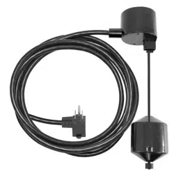
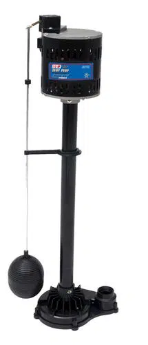
1. Barracuda pumps are equipped with a vertical magnetic oat switch. The pump will turn on automatically
when the water level in the sump reaches approximately the oat switch “on” level and automatically turn
off when the water is pumped down to the oat switch “off” level. Make sure the vertical oat switch does
not become bent, and can rise and fall without coming into contact with side of pump or side of pit. If the
oat switch cannot come down properly, the pump will not turn off, which will burn out the pump motor
and ood your basement!
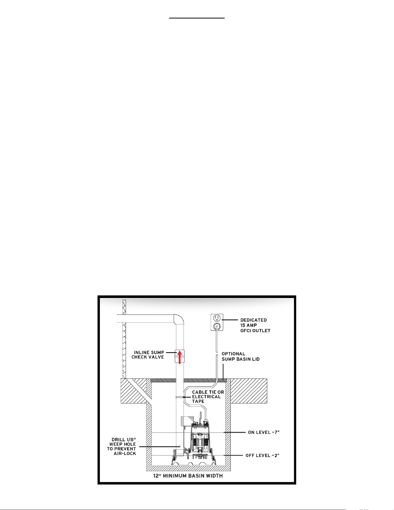
2. The sump pit must be a minimum of 12" diameter by 10" depth for vertical switch models.
3. Set your new pump in the bottom of the sump basin off to one side. The pump MUST be placed on
a solid foundation, such as a brick, stone paver, or other at heavy surface. Do not place the pump
directly on the ground in sandy or rocky surfaces. Clay, earth, sand, or gravel that enters the pump could
damage the impeller of the sump and cause ooding. Keep the pump inlet screen clear.
Do not set pump directly on sand, dirt or mud. Sand or mud-choked pumps can be back-
ushed clean.
Do not handle or carry the pump by the power cord. Use the handle.
Extended usage of the pump in a partially submerged or non-submerged situation may cause
the pump to overheat due to lack of heat dissipation from the water. If this occurs, the pump will shut itself off
until the motor cools to its normal temperature. Repeated overheating may cause damage to the pump.
The pump is not designed for application involving salt water or brine. Use with salt water or
brine will void warranty.
Materials Required:
• 1-1/2" ABS or PVC Pipe and adapter
• Inline sump check valve with clamps to connect
discharge pipe to drain line exiting house
• PVC Primer and Solvent to connect pipe to
adapter threaded into pump discharge
• Thread tape
Tools Required:
• Screwdriver
• Hacksaw to cut pipe
• Knife to assist in pipe cutting
• File to smooth pipe ends
• Adjustable wrench to tighten ttings
WARNING
WARNING
CAUTION
CAUTION
CAUTION
CAUTION
NOTICE
DANGER
4
INSTALLATION
1. For your own safety, turn off the electrical power at the service entrance to avoid any possible electrical
shock hazards.
2. On a replacement installation, remove the existing pump from the sump by disconnecting the discharge
pipe or hose from the old pump. Depending on how your old pump is installed, unscrew clamps and
discard old corrugated hose, or unscrew galvanized or plastic pipe from pump discharge. If discharge
pipe cannot be removed easily, saw through the pipe about 3-4 feet above the pump discharge.
3. After removing the old pump, remove sediment, debris, and any standing water from the sump pit.
4. Attach a PVC adapter (Male x Slip) to the pump discharge. Prepare a 3′-4′ section of PVC pipe (if not
re-using existing discharge pipe). Drill a 1/8" weep hole approximately 3" from bottom of pipe. This will
prevent pump from air-locking (see manual). NOTE: Make sure hole is drilled at downward angle so
water shoots down towards pit, not up and out of the pit!
5. Apply PVC primer and solvent to PVC adapter and 3′-4′ section of PVC pipe. Insert pipe into adapter
and allow solvent to set.
6. Place your pump in the sump and be sure that the pump is positioned so that the oat switch moves
freely without touching the wall of the sump or other obstructions. Ensure incoming water does not
interfere with oat switch.
7. Install an inline sump check valve (not included) onto the end of the section of pipe, making certain that
it is installed with the apper opening upward with the ow of water. Connect to remainder of discharge
pipe exiting through the wall. Tighten all clamps.
8. Plug the pump into a 115 V GFCI outlet on a dedicated 15-amp circuit. Do not allow the cord to interfere
with the oat control motion or to drape over the pump motor. With electrician’s tape and a cable
tie, secure the cord to the discharge pipe. This will provide protection for the cord and make a neat
installation. Test your installation after you have completed setting up the pump. Plug-in pump and
restore electrical power at the service entrance. The pump should not run at this point. If the pump runs,
the switch is stuck in the upright position, check the switch again.
9. Fill the sump basin with water using a bucket or hose. When the switch oats to the upright “on”
position, the pump will turn on. The switch will turn off the pump when it reaches the “off” down position.
10. Install a sump basin lid. A cover will prevent solid matter from falling into the sump, prevent odors, and
guards against accidental injury.

5
OPERATION
1. The pump’s shaft seal depends on water for lubrication. Do not operate the pump unless it is submerged
in water; running it dry may damage the seal and void warranty.The sump pit must be a minimum of 12"
diameter by 10" depth for vertical switch models.
2. If the pump overheats, an automatic-reset thermal protector cuts off the power and stops the motor
before it can be damaged. The motor will automatically restart when it cools. If the protector trips
repeatedly, unplug the pump, remove it from the sump, and check it for the cause of the difculty. Low
voltage, long extension cords (which should not be used), clogged impeller, very low lift, a plugged or
frozen discharge pipe, etc., can all cause cycling and overheating.
3. This pump will not remove all the water in the sump. If you are running the pump manually and water
stops coming out of the discharge, the pump has probably run dry. Shut it off immediately and check the
water level.
TROUBLESHOOTING (CAUTION: SHUT OFF POWER TO THE PUMP)
PROBLEMS POSSIBLE CAUSES / SOLUTIONS
Pump does not run
or it hums.
• Line circuit breaker is off, or fuse is burned or loosed. Reset breaker or
replace fuse.
• Water level in sump has not reached turn-on level as indicated in
installation drawing.
• Pump cord is not making contact in receptacle. Re-insert plug.
• Float is stuck. It should operate freely in basin.
Pump runs but does
not deliver water.
• Check valve is installed backwards. Flapper should open in direction of
water.
• Discharge shut-off valve (if used) may be closed.
• Impeller or volute openings are fully or partially clogged. Remove pump
and clean.
• Pump is air-locked. Start and stop several times by plugging and
unplugging cord. Check for clogged vent hole in pump case.
• Vertical pumping distance (“head”) is too high. Reduce distance or
increase diameter of discharge pipe/hose.
• Discharge pipe/hose could be frozen. Thaw pipe/hose or remove and
replace.
Pump runs and
pumps out sump,
but does not stop.
• Float is stuck in up position. Be sure oat operates freely in basin.
• Defective oat switch. Replace with new oat switch.
Pump runs but
delivers only a small
amount of water.
• Pump is air-locked. Start and stop several times by plugging and
unplugging cord. Check for clogged vent hole in pump case.
• Vertical pumping distance (“head”) is too high. Reduce distance or
increase diameter of discharge pipe/hose.
• Impeller or volute openings are fully or partially clogged. Remove pump
and clean.
Fuse blows or circuit
breaker trips when
pump starts.
• Pump impeller is partially clogged with debris, causing motor to run slow
and overload. Remove pump and clean.
• Motor stator may be defective. Call 1-844-251-7445.
• Fuse size or circuit breaker may be too small. 15-amp minimum is
required.
6
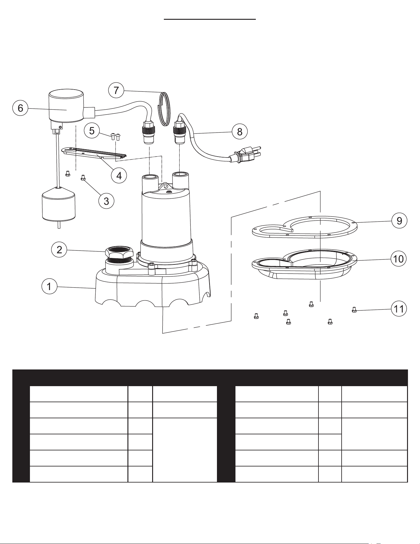
REPLACEMENT PARTS
To order replacement parts, call:
1-844-251-7445
# Description Qty Repair Kit # Description Qty Repair Kit
1 Pump Casing & Motor 1 N/A 7 Handle 1 N/A
2 Adapter 1 BUSH-125-150 8 Power Cord 1 N/A
3 Screw 2
WSBAS-RS
9 Gasket 1
WSBAS-PBG
4 Bracket 1 10 Pump Base 1
5 Screw 2 11 Screw 6 N/A
6 Vertical Float Switch 1

7
PERFORMANCE
Power supply requirement:
Motor:
Amps:
Liquid Temperature Range:
Circuit Requirements:
Solids Handling:
Discharge Size:
115 V, 60 Hz
1/3 HP, Continuous Duty, Permanent Split Capacitor, Thermally Protected
4
32° F - 120° F (0° C - 49° C)
15 amp minimum
1/2"
1-1/2" FIP
SPECIFICATIONS
WARRANTY
LIMITED WARRANTY - RESIDENTIAL SUMP PUMPS (NOT INCLUDING FLOAT SWITCH):
Barracuda Pump (The “Company”) warrants that the products specied in this warranty are free from defects
in material or workmanship for the life of the product. During the time period and subject to the terms and
conditions, the Company will repair or replace to the original purchaser or consumer any portion of this
product which proves to be defective due to materials or workmanship. At all times the Company shall have
and possess the sole right and option to determine whether to repair or replace defective equipment, parts,
or components. The Company has the option to inspect any product returned under warranty to conrm that
the warranty applies before repair or replacement under warranty is approved. This warranty sets forth the
Company’s sole obligation and purchaser’s exclusive remedy for defective product.
For all warranty claims, CALL OUR CUSTOMER SERVICE DEPARTMENT BEFORE RETURNING!
Call us at 1-844-251-7445, Monday – Friday, 8:00 a.m. – 4:30 p.m., EST to discuss any claims and/or
to obtain a Return Merchandise Authorization. DO NOT RETURN PRODUCT TO STORE WHERE
PURCHASED. If deemed necessary, the Company will provide instructions for returning, prepaid at the
purchaser’s cost, to the Company’s warranty department along with your original purchase receipt.
LIMITED WARRANTY - FLOAT SWITCH:
The Company warrants for a period of 12 months from the date of purchase that the oat switch is free
from defects in material or workmanship. During the time period and subject to the terms and conditions,
the Company will repair or replace to the original purchaser or consumer any portion of this product
which proves to be defective due to materials or workmanship. At all times the Company shall have and
possess the sole right and option to determine whether to repair or replace defective equipment, parts, or
components. The Company has the option to inspect any product returned under warranty to conrm that
the warranty applies before repair or replacement under warranty is approved. This warranty sets forth the
Company’s sole obligation and purchaser’s exclusive remedy for defective product.
MODEL #
MAX FLOW
(GPM) @ 0′
GPM FLOW @ HEAD
MAX
HEAD (FT)
5′ 10′ 15′ 20′ 25′
BAS33V-1-10 75 68 55 35 15 0 25

8
WARRANTY PERIOD - PRODUCTS:
If, within the duration of product use by the original purchaser, this product proves to be defective due to
materials or workmanship, the product shall be repaired or replaced at the Company’s option, subject to
the terms and conditions set forth in this warranty statement. Proof of purchase is required for warranty
consideration. In the absence of suitable proof of the purchase date, the effective period of this warranty is
12 months from the product’s date of manufacture.
LABOR, ETC. COSTS:
The Company shall IN NO EVENT be responsible or liable for the cost of eld labor or other charges
incurred by any customer in removing and/or afxing any product, part, or component thereof.
PRODUCT IMPROVEMENTS:
The Company reserves the right to change or improve its products or any portions thereof without being
obligated to provide such a change or improvement for units sold and/or shipped prior to such change or
improvement.
GENERAL TERMS AND CONDITIONS:
This warranty shall not apply to damage due to acts of God, normal wear and tear, normal maintenance
services and the parts used in connection with such service, lightning or conditions beyond the control of
the Company, nor shall it apply to products which, in the sole judgment of the Company, have been subject
to negligence, abuse, accident, misapplication, tampering, alteration; nor due to improper installation,
operation, maintenance or storage; nor to excess of recommended maximums as set forth in the
instructions. Warranty will be VOID if any of the following conditions are found:
1. Product is used for purposes other than those for which it was designed and manufactured
2. Product not installed in accordance with applicable codes, ordinances, and good trade practices
3. Product connected to voltage other than indicated on nameplate
4. Pump exposed to but not limited to the following: sand, gravel, cement, grease, plaster, mud, tar, oil,
gasoline, solvents or other abrasive or corrosive substances
5. Pump has been used for pumping liquids above 120°F
6. Pump allowed to operate dry (liquid supply cut off)
7. Sealed motor housing opened or product dismantled by customer
DISCLAIMER:
Any oral statements about the product made by the seller, the Company, the representatives, or any other
parties do not constitute warranties, shall not be relied upon by the purchaser, and are not part of the
contract for sale. The Seller’s and the Company only obligation, and buyer’s only remedy, shall be the
replacement and/or repair by the Company of the product as described above. NEITHER SELLER NOR
THE COMPANY SHALL BE LIABLE FOR ANY INJURY, LOSS OR DAMAGE, DIRECT, INCIDENTAL
OR CONSEQUENTIAL (INCLUDING, BUT NOT LIMITED TO, INCIDENTAL OR CONSEQUENTIAL
DAMAGES FOR LOST PROFITS, LOST SALES, INJURY TO PERSON OR PROPERTY, OR ANY OTHER
INCIDENTAL OR CONSEQUENTIAL LOSS), ARISING OUT OF THE USE OR THE INABILITY TO USE
THE PRODUCT, AND THE PURCHASER AGREES THAT NO OTHER REMEDY SHALL BE AVAILABLE
TO IT. Before using, the purchaser shall determine the suitability of the product for his/her intended use, and
purchaser assumes all risk and liability whatsoever in connection therewith.

9
THE WARRANTY AND REMEDY DESCRIBED IN THIS LIMITED WARRANTY IS AN EXCLUSIVE
WARRANTY AND REMEDY AND IS IN LIEU OF ANY OTHER WARRANTY OR REMEDY, EXPRESSED
OR IMPLIED, WHICH OTHER WARRANTIES AND REMEDIES ARE HEREBY EXPRESSLY EXCLUDED,
INCLUDING BUT NOT LIMITED TO ANY IMPLIED WARRANTY OF MERCHANTABILITY OR FITNESS
FOR A PARTICULAR PURPOSE, TO THE EXTENT EITHER APPLIES TO A PRODUCT SHALL BE
LIMITED IN DURATION TO THE PERIODS OF THE EXPRESSED WARRANTIES GIVEN ABOVE.
Some states and countries do not allow the exclusion or limitations on how long an implied warranty lasts or
the exclusion or limitation of incidental or consequential damages, so the above exclusion or limitations may
not apply to you. This warranty gives you specic legal rights, and you may also have other rights which vary
from state to state.
MODEL: BAS33V-1-10
SKU#: 691-3312
BA-0004 C24