
SKU: 691-1259
Model # 92010
UNIVERSAL VERTICAL FLOAT SWITCH
BA92010 Manual Rev: 1411
Inventory
1. Universal vercal oat switch (1)
2. Stainless Steel Hose Clamp (1)
3. Stainless Steel Mounng Bracket (1)
4. Mounng Screws (2)
LIMITED WARRANTY
Manufacturer warrants the products specied in this warranty to be free from defects in material or workmanship for one (1) year from date of purchase. During the me period and
subject to the terms and condions, the manufacturer will repair or replace to the original user or consumer any poron of this product which proves to be defecve due to materials or
workmanship. At all mes the manufacturer shall have and possess the sole right and opon to determine whether to repair or replace defecve equipment, parts, or components. The
manufacturer has the opon to inspect any product returned under warranty to conrm that the warranty applies before repair or replacement under warranty is approved. This warranty
sets forth the manufacturer’s sole obligaon and purchaser’s exclusive remedy for defecve product. Return defecve product to the place of purchase for warranty consideraon.
WARRANTY PERIOD - PRODUCTS:
If, within the duraon of product use by the original user, this product proves to be defecve due to materials or workmanship, the product shall be repaired or replaced at the
manufacturer’s opon, subject to the terms and condions set forth in this warranty statement. Proof of purchase is required for warranty consideraon. In the absence of suitable proof
of the purchase date, the eecve period of this warranty is 12 months from the product’s date of manufacture.
LABOR, ETC. COSTS:
The manufacturer shall IN NO EVENT be responsible or liable for the cost of eld labor or other charges incurred by any customer in removing and/or axing any product, part, or
component thereof.
PRODUCT IMPROVEMENTS:
The manufacturer reserves the right to change or improve its products or any porons thereof without being obligated to provide such a change or improvement for units sold and/or
shipped prior to such change or improvement.
GENERAL TERMS AND CONDITIONS:
This warranty shall not apply to damage due to acts of God, normal wear and tear, normal maintenance services and the parts used in connecon with such service, lightning or condions
beyond the control of the manufacturer, nor shall it apply to products which, in the sole judgment of the manufacturer, have been subject to negligence, abuse, accident, misapplicaon,
tampering, alteraon; nor due to improper installaon, operaon, maintenance or storage; nor to excess of recommended maximums as set forth in the instrucons. Warranty will be
VOID if any of the following condions are found:
1. Product is used for purposes other than those for which it was designed and manufactured
2. Product not installed in accordance with applicable codes, ordinances, and good trade pracces
3. Product connected to voltage other than indicated on nameplate or labels
DISCLAIMER:
Any oral statements about the product made by the seller, the manufacturer, the representaves, or any other pares do not constute warranes, shall not be relied upon by the user,
and are not part of the contract for sale. Seller’s and the manufacturers only obligaon, and buyer’s only remedy, shall be the replacement and/or repair by the manufacturer of the
product as described above. NEITHER SELLER NOR THE MANUFACTURER SHALL BE LIABLE FOR ANY INJURY, LOSS OR DAMAGE, DIRECT, INCIDENTAL OR CONSEQUENTIAL (INCLUDING, BUT
NOT LIMITED TO, INCIDENTAL OR CONSEQUENTIAL DAMAGES FOR LOST PROFITS, LOST SALES, INJURY TO PERSON OR PROPERTY, OR ANY OTHER INCIDENTAL OR CONSEQUENTIAL LOSS),
ARISING OUT OF THE USE OR THE INABILITY TO USE THE PRODUCT, AND THE USER AGREES THAT NO OTHER REMEDY SHALL BE AVAILABLE TO IT. Before using, the user shall determine
the suitability of the product for his/her intended use, and user assumes all risk and liability whatsoever in connecon therewith.
THE WARRANTY AND REMEDY DESCRIBED IN THIS LIMITED WARRANTY IS AN EXCLUSIVE WARRANTY AND REMEDY AND IS IN LIEU OF ANY OTHER WARRANTY OR REMEDY,
EXPRESSED OR IMPLIED, WHICH OTHER WARRANTIES AND REMEDIES ARE HEREBY EXPRESSLY EXCLUDED, INCLUDING BUT NOT LIMITED TO ANY IMPLIED WARRANTY OF
MERCHANTABILITY OR FITNESS FOR A PARTICULAR PURPOSE, TO THE EXTENT EITHER APPLIES TO A PRODUCT SHALL BE LIMITED IN DURATION TO THE PERIODS OF THE EXPRESSED
WARRANTIES GIVEN ABOVE.
Some states and countries do not allow the exclusion or limitaons on how long an implied warranty lasts or the exclusion or limitaon of incidental or consequenal damages, so the
above exclusion or limitaons may not apply to you. This warranty gives you specic legal rights, and you may also have other rights which vary from state to state.
Customer Support
800-495-9278
barracudapumps.com
Risk of electrical shock. Can burn or kill. To reduce risk of electrical shock, disconnect power supply before replacing switch. Make sure
switch is connected only to a properly grounded grounding type receptacle.
Short circuit electrical hazard. An incorrect connection may cause electric shock, or burn out the pump motor, resulting in property damage
or personal injury. Make sure all connections are correct before plugging the switch into the outlet.
The outlet voltage and pump voltage must match. Ensure voltage is correct before installing switch. The electrical outlet must be installed
outside the pump basin.
Risk of flooding. It is recommended to operate the pump through two or three complete cycles to ensure proper liquid level control.
Assembly
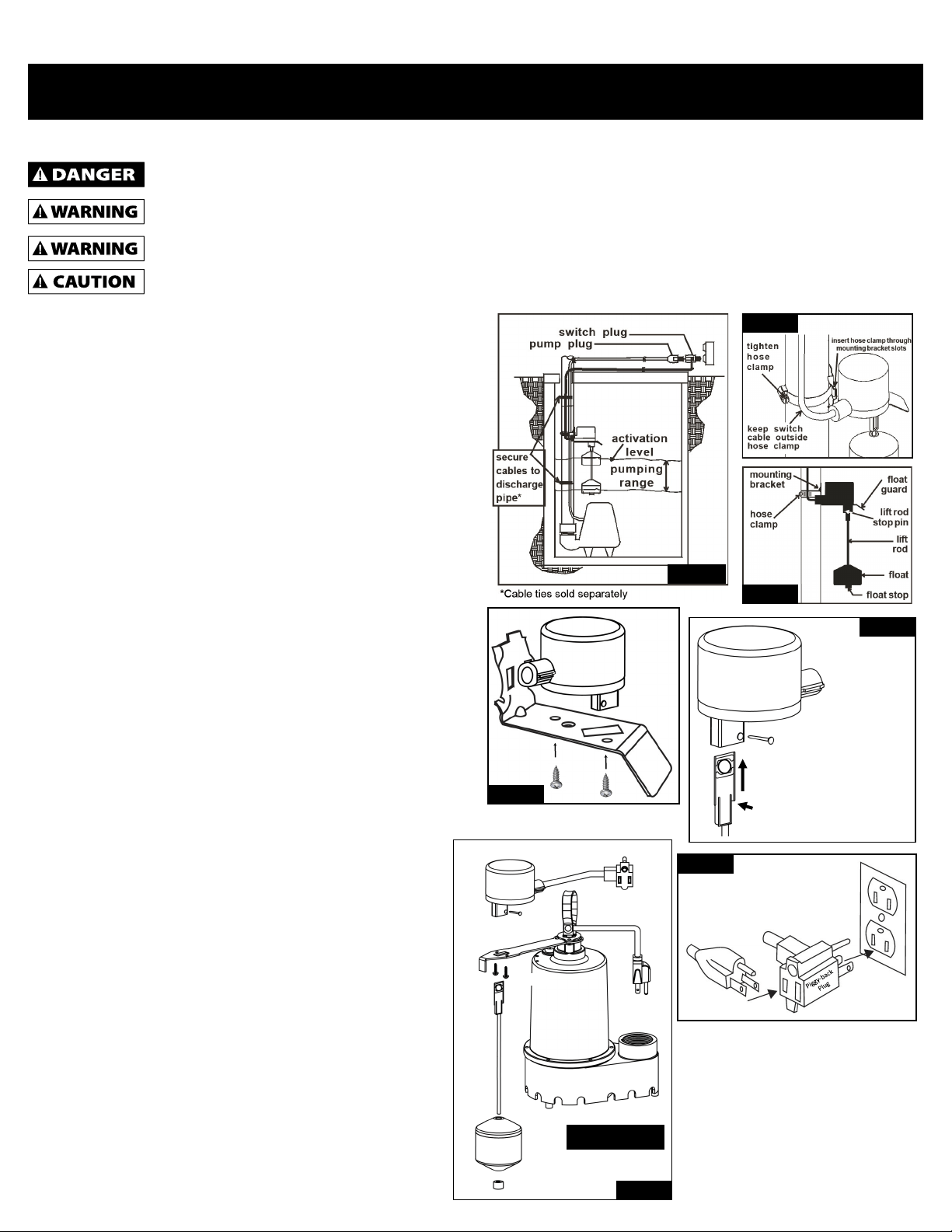
1. Aach mounng bracket to the oat switch housing using the
two screws provided. See Figure 3. NOTE: Make sure the
mounng bracket is installed before securing the oat rod to
avoid assembly problems.
2. Fully insert the oat rod into the oat switch housing making
sure the notch in the oat rod is aligned with the stop pin hole.
Secure oat rod with the stop pin. See Figure 3.
3. Slide the oat ball onto the oat rod and secure with the oat
stop. See Figure 4.
Switch Replacement Instructions for
Barracuda Brand Pumps
1. Remove the old switch from the pump.
2. Install the new switch onto the exisng pump bracket
using the two provided screws. See Figure 6.
3. Fully insert the oat rod into the oat switch housing
making sure the notch in the oat rod is aligned with the
stop pin hole. Secure oat rod with the stop pin. See
Figure 5.
4. Slide the oat ball onto the oat rod and secure with the
oat stop. See Figure 6.
5. Plug the piggyback plug into a grounded outlet, then plug
the pump into the piggyback plug. Refer to Figure 7.
6. Check for proper operaon by lling the pump basin with
water. Make sure the pump operates at the desired
levels. Make any necessary adjustments at this me.
SKU: 691-1259
UNIVERSAL VERTICAL FLOAT SWITCH
Safety Guidelines
To Outlet
Figure 7
Plug Pump in here
Figure 2
Figure 1
Figure 4
Switch
Pin
Screws
Float
Rod
Float
Ball
Float Stop
*Bracket
Pump
Sold
Separately
*Pump and Bracket
Sold Separately
Figure 6
Notch
Pin
Switch
Figure 3
The oat rod must
be inserted with the
notch facing
towards the side
where the pin is
inserted. Fully insert
the oat rod into
the switch before
inserng the pin.
Installation and Operating Instructions
1. Determine desired acvaon level and pumping range as shown
in Figure 1. Pumping range can be adjusted by moving the oat
stop up or down on the oat rod.
2. Insert hose clamp through slots in mounng bracket as shown in
Figure 2.
3. Posion hose clamp around discharge pipe with bracket gripping
tabs against pipe. Cable should remain outside of hose clamp.
4. Tighten the hose clamp securely. Do not over ghten.
5. Secure the excess pump cable and switch cable to discharge pipe
as shown in Figure 1*.
6. Plug the piggyback plug into a grounded outlet, then plug the
pump into the piggyback plug. Refer to Figure 7.
7. Check for proper operaon by lling the pump basin with water.
Make sure the pump operates at the desired levels. Make any
necessary adjustments at this me.
Figure 5
Figure 3