Visit our website at: http://www.harborfreight.com
Email our technical support at: [email protected]
Do not return
pump to the store.
Call 1-844-416-9141
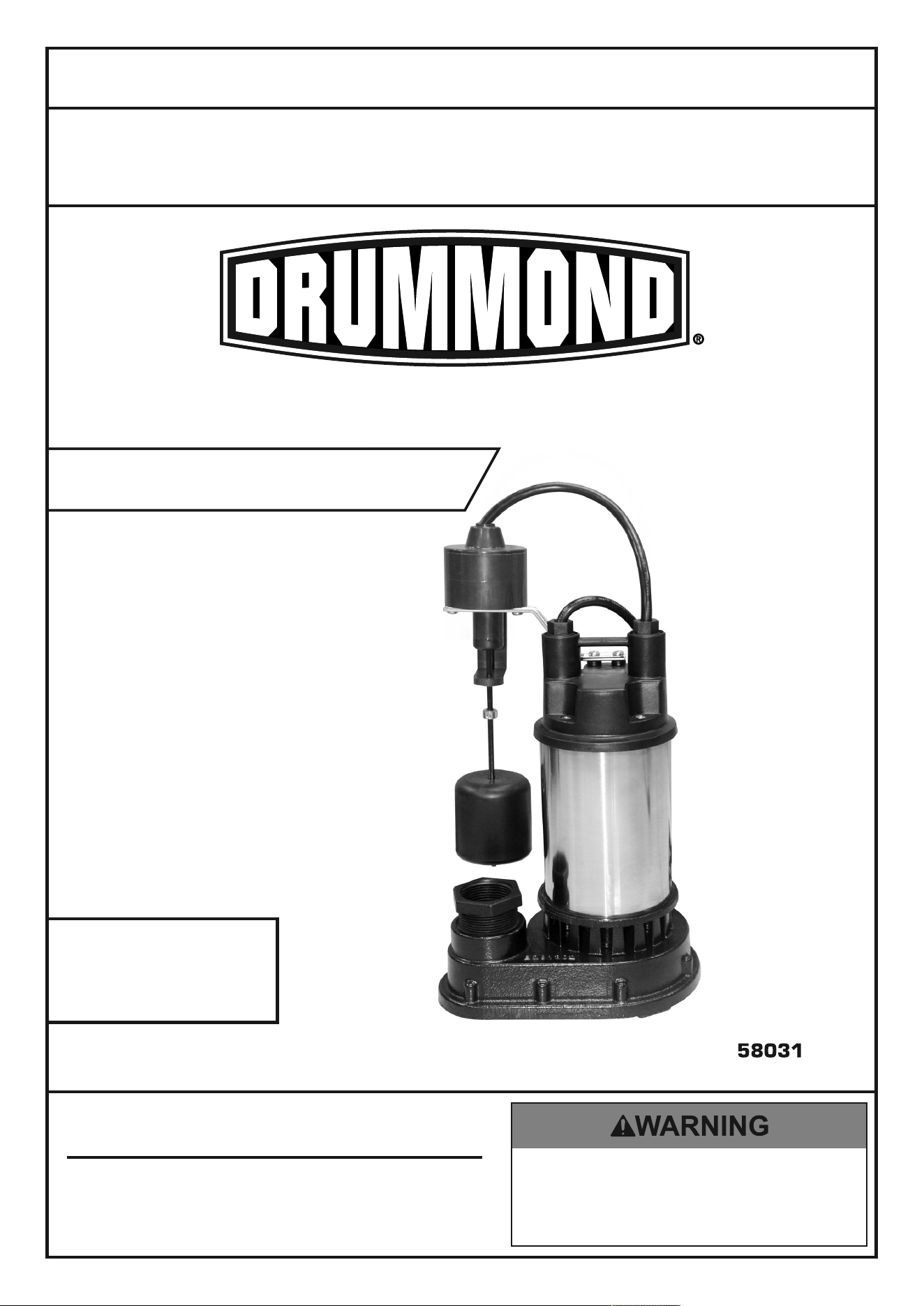
1 HP SUBMERSIBLE
SUMP PUMP
Owner’s Manual & Safety Instructions
Save This Manual Keep this manual for the safety warnings and precautions, assembly,
operating, inspection, maintenance and cleaning procedures. Write the product’s serial number in the
back of the manual near the assembly diagram (or month and year of purchase if product has no number).
Keep this manual and the receipt in a safe and dry place for future reference. 20l
When unpacking, make sure that the product is intact
and undamaged. If any parts are missing or broken,
please call 1-888-866-5797 as soon as possible.
Copyright
©
2020 by Harbor Freight Tools
®
. All rights reserved.
No portion of this manual or any artwork contained herein may be reproduced in
any shape or form without the express written consent of Harbor Freight Tools.
Diagrams within this manual may not be drawn proportionally. Due to continuing
improvements, actual product may differ slightly from the product described herein.
Tools required for assembly an d se rv ic e may n ot b e in cl uded.
Read this material before using this product.
Failure to do so can result in serious injury.
SAVE THIS MANUAL.
Page 2 For technical questions, please call 1-888-866-5797. Item 58031
Before start-up, note the following:
The pump must be connected to a GFCI protected plug which has been installed according
to regulations. The plug must have a supply voltage of 120 VAC at 60 Hz.
CAUTION
This pump has been evaluated for use with water only.
WARNING
IMPORTANT! For your own safety –
before starting to run the pump, please have
the following items checked by an expert:
1. Risk of electric shock – This pump is supplied
with a grounding conductor and grounding-type
attachment plug. To reduce the risk of electric shock,
be certain that it is connected only to a properly
grounded, grounding-type receptacle.
2. Risk of electric shock – This pump has not been
investigated for use in swimming pool areas.
3. The electrical connections must be
protected from moisture.
4. If there is danger of flooding, the electrical
connections must be taken to higher ground.
5. Circulation of caustic fluids, as well as the circulation
of abrasive materials, must be avoided at all costs.
6. The pump must be protected from frost.
7. The pump must be protected from running dry.
8. Access by children should also be
prevented with appropriate measures.
9. To prevent death from electric shock,
pump must be connected only to a GFCI
protected outlet.
10. Do not use an extension cord with this item.
11. People with pacemakers should consult their
physician(s) before use. Electromagnetic fields in
close proximity to heart pacemaker could cause
pacemaker interference or pacemaker failure.
12. The warnings, precautions, and instructions
discussed in this instruction manual cannot cover all
possible conditions and situations that may occur.
It must be understood by the operator that
common sense and caution are factors
which cannot be built into this product, but
must be supplied by the operator.
Fluid Type
The Pump is designed for use with water with a maximum temperature of 77° F (25°C). Do not use the pump
for other fluids, especially not fuels, cleaning fluids, or other chemical products.
Page 3For technical questions, please call 1-888-866-5797.Item 58031
Specifications
Electrical Rating 120 VAC / 60 Hz
Amperage 10A
Power 1 HP
Power Cord Length 8’
6000 GPH
Maximum Head lift @ 0 Flow 30’
Discharge Port
Installation
The submersible motor pump must be installed in a stationary position with either:
a. A fixed pipeline or
b. A flexible hose pipe.
Please note!
1. Do not install the pump by suspending it
unsupported from its delivery pipe or power cord.
The pump must be suspended from the handle
or be placed on the bottom of the basin.
To ensure that the pump works properly,
keep the bottom of the basin free from
sludge and dirt of all kinds.
2. If the water level sinks too low, any sludge in the
basin will dry out and stop the pump from starting.
To help ensure the pump will start as required,
check the pump regularly with start-up tests.
Power Supply
1. The pump is equipped with a shock-proof plug
according to regulations. The pump is designed to be
connected to 120 VAC, 60 Hz GFCI protected socket.
2. Make sure that the socket is sufficiently
secured and is in excellent condition.
3. When the plug is inserted into the socket,
the pump will be on standby.
4. WARNING: To prevent death from electric
shock, pump must be connected only to
a GFCI protected outlet.
WARNING! TO PREVENT SERIOUS INJURY:
If the power cord or plug is damaged, do not
use the pump. The power cord or plug may
only be repaired by a certified electrician.
Areas of use
1. This pump is designed to pump water only.
2. This pump is designed to be used for:
Removing groundwater from
basements and crawl spaces.
3. This pump should NOT be used for:
Continuous run, fountain/pond water features.
Removing water from swimming pools or
spas. Septic or sewage systems.
4. This pump can also be used to transfer water
(e.g. household, farming, plumbing).
Page 4 For technical questions, please call 1-888-866-5797. Item 58031
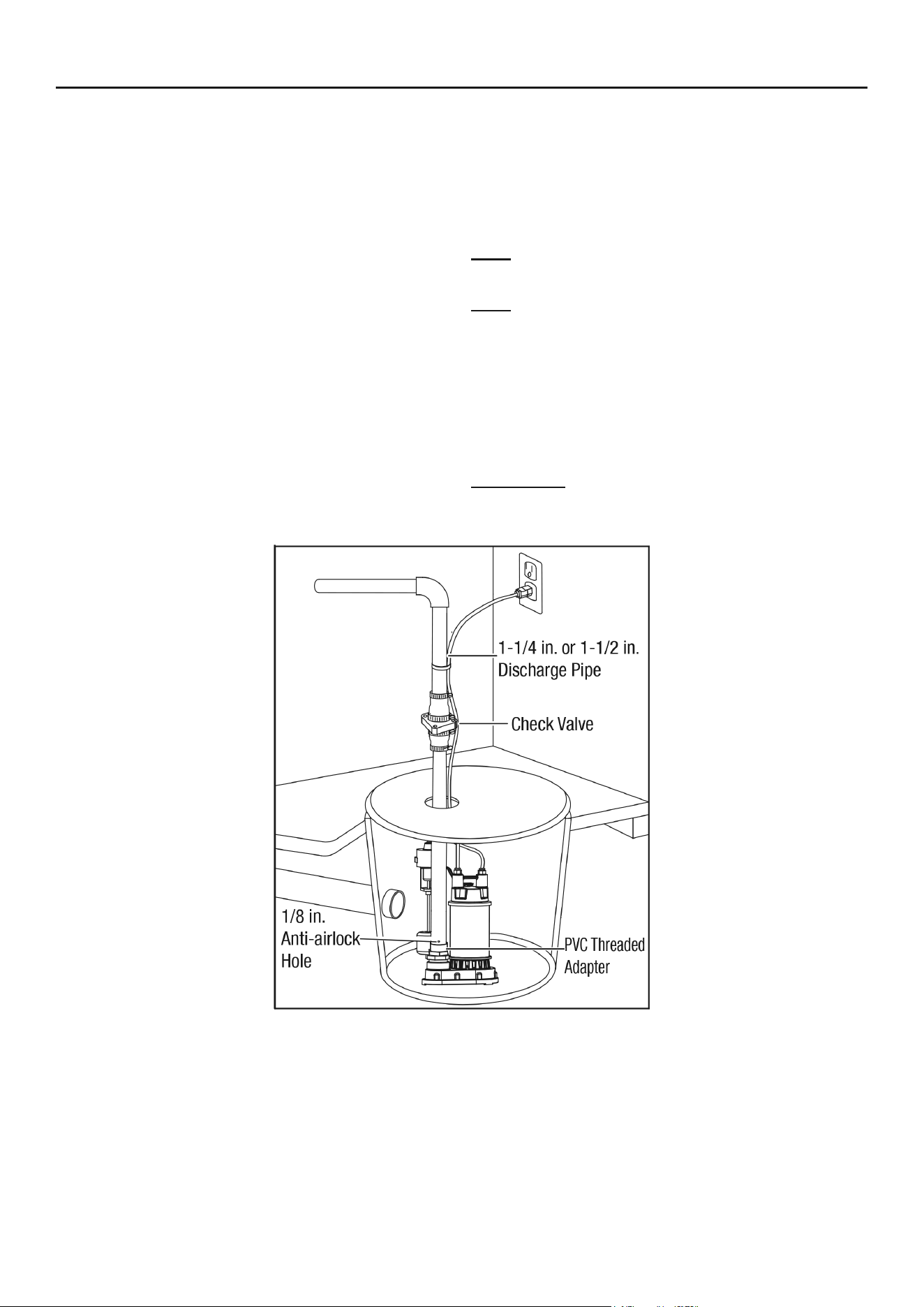
Installation Instructions
1. Construct a sump basin that is at least
deep and at least in diameter. Clear
basin of any debris that could clog pump.
2. Position Pump on solid surface so that both
hoses are free from kinks the Float Switch is
from all obstructions throughout its movement.
3. Install discharge plumbing. Insert rigid pipe
into the male adapter and screw into place.
4. To prevent excessive cycling from backflow of
water, install a check valve (sold separately)
onto the discharge pipe. This prevents water
from flowing back after the pump shuts off.
5. Fit a sump cover with a hole for the discharge
pipe and a hole for the power cords. Thread the
Power Cords through their holes, but do not
plug them in yet. Set the sump cover aside
for now. Place unused end of discharge hose
the other end as needed to direct the water
discharge at least 3 feet away from the source.
Note: The sump cover can also be
fitted with a vent pipe, if desired.
Note: Wrap all threaded connections
with PTFE thread seal tape.
6. Connect additional Discharge Pipe as needed
to direct the water discharge at least 3 feet
away from the foundation. Slope the discharge
pipe downward, away from the foundation.
The discharge should be kept as short as
possible with a minimum number of turns.
IMPORTANT: Do not exceed the
Maximum Head Lift @ 0 Flow of the Pump.
Figure A: Sump Pump Installation

Page 5For technical questions, please call 1-888-866-5797.Item 58031
Operation
After reading these instructions, consider the following points before starting the pump:
1. Verify that the pump rests on the floor of the basin.
2. Verify that the discharge pipe is properly connected.
3. Verify that the electrical connection
is 120 VAC, 60 Hz.
4. Verify that the electrical socket is GFCI
protected and in good condition. Test
GFCI protected outlet before use.
5. Verify that water and moisture cannot
get near the power supply socket.
6. Verify that the pump is installed so
as to prevent running dry.

Page 6 For technical questions, please call 1-888-866-5797. Item 58031
Maintenance
TO PREVENT SERIOUS INJURY FROM ACCIDENTAL OPERATION:
Unplug the Pump from its electrical outlet before performing any
inspection, maintenance, or cleaning procedures.
If the pump is moved during operation, flush it out with clean water after every use.
Quarterly Maintenance
The below maintenance must be performed at least once every 3 months under optimal conditions.
For frequent use, or dirty areas, more frequent maintenance is required.
1. Clean sludge and debris from the bottom of the basin.
2. Clean sludge/debris from inlet screen.
3. Make sure discharge pipe is free from leaks.
4. Make sure check valve is functioning properly.
5. Manually operate flow switch to determine
that pump turns on/off as intended.
Page 7For technical questions, please call 1-888-866-5797.Item 58031
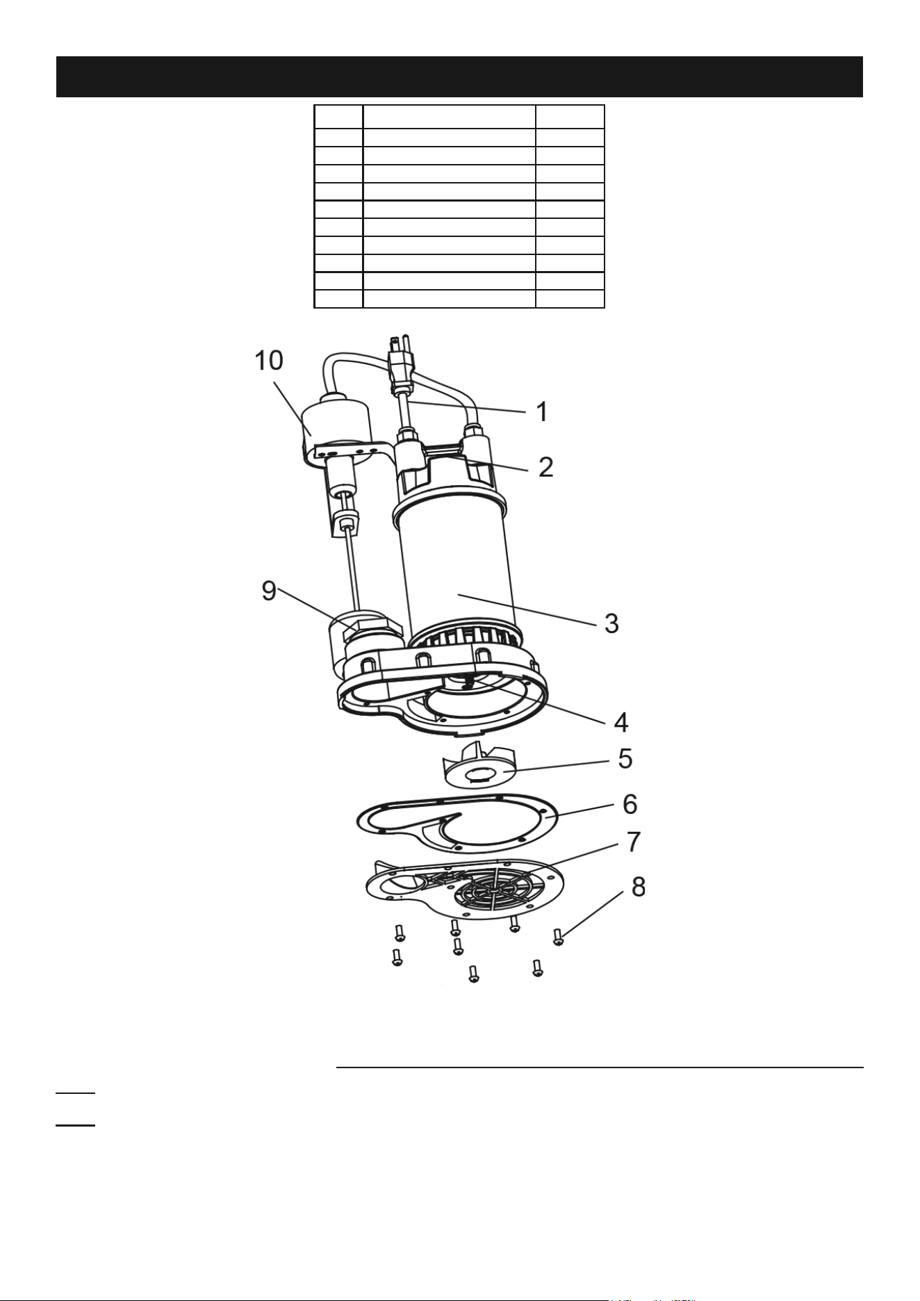
Parts List and Diagram
Part Description Qty.
1 Pump Cord 1
2 Handle 1
3 Motor 1
4 Shaft 1
5 Impeller 1
6 Gasket 1
7 Volute 1
8 Screw 7
9 Adaptor 1
10 Float Switch 1
Record Product’s Serial Number Here:
Note: If product has no serial number, record month and year of purchase instead.
Note: Some parts are listed and shown for illustration purposes only, and are not available
individually as replacement parts. Specify UPC 193175430991 when ordering parts.

Limited 90 Day Warranty
Harbor Freight Tools Co. makes every effort to assure that its products meet high quality and durability standards,
and warrants to the original purchaser that this product is free from defects in materials and workmanship for the
period of 90 days from the date of purchase. This warranty does not apply to damage due directly or indirectly,
to misuse, abuse, negligence or accidents, repairs or alterations outside our facilities, criminal activity, improper
installation, normal wear and tear, or to lack of maintenance. We shall in no event be liable for death, injuries
to persons or property, or for incidental, contingent, special or consequential damages arising from the use of
our product. Some states do not allow the exclusion or limitation of incidental or consequential damages, so the
above limitation of exclusion may not apply to you. THIS WARRANTY IS EXPRESSLY IN LIEU OF ALL OTHER
WARRANTIES, EXPRESS OR IMPLIED, INCLUDING THE WARRANTIES OF MERCHANTABILITY AND FITNESS.
To take advantage of this warranty, the product or part must be returned to us with transportation charges
prepaid. Proof of purchase date and an explanation of the complaint must accompany the merchandise.
If our inspection verifies the defect, we will either repair or replace the product at our election or we may
elect to refund the purchase price if we cannot readily and quickly provide you with a replacement. We will
return repaired products at our expense, but if we determine there is no defect, or that the defect resulted
from causes not within the scope of our warranty, then you must bear the cost of returning the product.
This warranty gives you specific legal rights and you may also have other rights which vary from state to state.
26541 Agoura Road • Calabasas, CA 91302 • 1-888-866-5797