REVISED BULLETIN DATE
SERVICE PARTS LIST
BULLETIN NO.
WIRING INSTRUCTION
SERIAL
NUMBER
MILWAUKEE ELECTRIC TOOL CORPORATION
13135 W. LISBON RD., BROOKFIELD, WI 53005
Drwg. 4
®
SPECIFY CATALOG NO. AND SERIAL NO. WHEN ORDERING PARTS
CATALOG NO.
EXAMPLE:
Component Parts (Small #)
Are Included When Ordering
The Assembly (Large #).
00
0
58-01-0705
Nov. 2002
54-37-0125
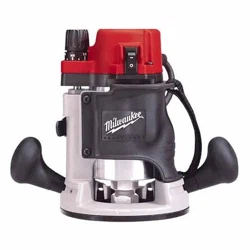
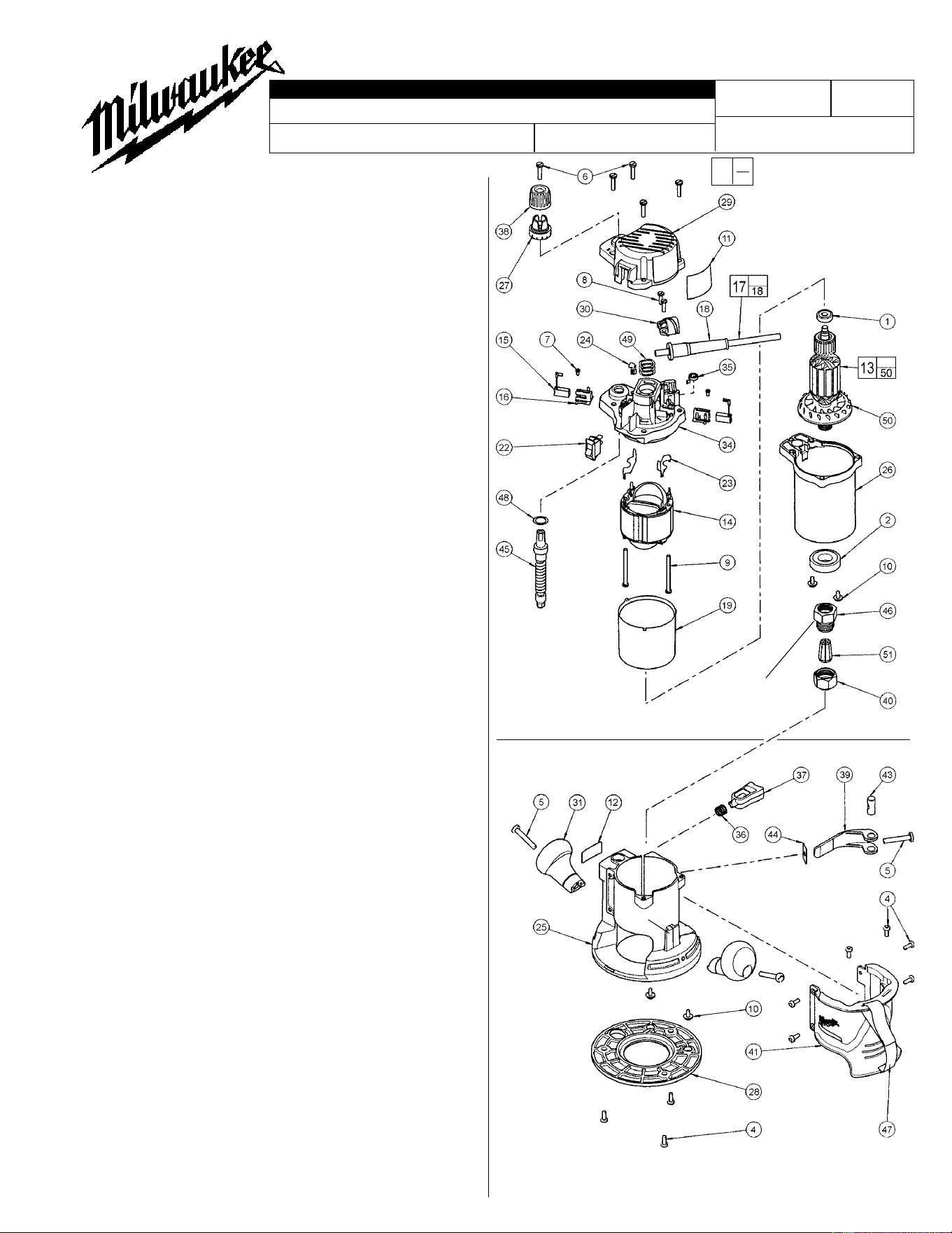
5615-29
1-3/4 H.P. BODY GRIP ROUTER
279A
FIG. PART NO. DESCRIPTION OF PART QTY.
1 02-04-0852 Ball Bearing (1)
2 02-04-2005 Ball Bearing (1)
4 06-82-5314 10-24 x 1/2" Slt. Pan Hd. Tapt. T-25 (9)
5 06-82-5514 1/4-20 x 1-1/2" Slt. Pan Hd. Tapt. T-30 (3)
6 06-82-5574 10-24 x 7/8" Pan Hd. Slt. Tapt. T-25 (5)
7 06-82-7212 4-20 x 1/4" Pan Hd. Slt. Plast. T-10 (2)
8 06-82-7270 8-16 x 5/8" Pan Hd. Slt. Plast. T-20 (2)
9 06-82-7455 8-16 x 2-3/8" Pan Hd. Slt. Plast. T-20 (2)
10 06-82-8865 10-32 x 7/16" Pan Hd. Tapt. Sems T-25 (4)
11 12-20-0145 Service Nameplate Kit (1)
12 12-25-0235 Nameplate (1)
13 16-30-0010 Armature (1)
14 18-30-1010 Field (1)
15 22-16-0410 Carbon Brush (2)
16 22-22-0165 Brush Tube (2)
17 22-64-7777 Cord Set Assembly (1)
18 44-76-0210 Cord Protector (1)
19 23-16-0405 Field Insulator (1)
22 23-66-2275 Rocker Switch (1)
23 23-74-0025 Field Terminal (2)
24 23-74-0055 Connector Terminal (1)
25 26-06-0100 Base (1)
26 28-50-0105 Motor Housing (1)
27 31-01-0025 Depth Scale (1)
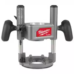
28 49-54-1045 Sub Base (1)
29 31-15-0065 Motor Cover (1)
30 31-17-0070 Cord Clamp (1)
31 31-44-0130 Knob Handle (2)
34 31-50-0105 Motor Frame (1)
35 40-50-0190 Brush Spring (2)
36 40-50-4005 Compression Spring (1)
37 42-42-0125 Release Button (1)
38 43-98-0530 Depth Knob (1)
39 44-10-0435 Base Clamp Lever (1)
40 44-40-0095 Collet Nut (2 supplied with tool) (1)
41 44-52-0020 Body Grip (1)
43 44-60-0095 Thru Pin (1)
44 44-66-0035 Wear Plate (1)
45 45-08-0030 Depth Shaft Assembly (1)
46 45-10-0080 Collet Shank
(See reverse side for servicing)
(1)
47 45-56-0225 Handle Strap Assembly (1)
48 45-88-0045 Washer (1)
49 45-88-0577 Wave Spring Washer (3)
50 22-84-0380 Fan Assembly (1)
51 48-66-0985 1/4" Collet (1)
51 48-66-1010 1/2" Collet (1)
49-96-0365 1-1/8" Open End Wrench (Not Shown) (2)
FIG. NOTES:
5,39 Clamping force for the base clamp lever (39) is adjusted
with base clamp screw (5). Tighten the screw using
10-20 lbs. force to close the lever to the locked position.
Motor unit must be in base when checking force.
16,34 When servicing the motor frame (34) and the brush tube
(16) has to be removed, replace with a new brush tube.
25,36,37 To service the release button (37) and the compression
spring (36) a long, thin tool like a flat blade screwdriver
must be used. From the bottom of the base (25), insert the
screwdriver into the cavity located under the release
button. Press on the button detent to release.
25,41,47 The metal clip from the handle strap (47) is to be placed
around the tab on the base (25). The body grip (41) is to be
placed onto the base from the top so that the cavity on the
inside of the body grip slips over the tab on the base,
securing the handle strap.
39,43 Apply a thin coat of "L" grease, No. 49-08-4170, to the
pivot surface areas of the base clamp lever (39). Apply a
thin coat of grease to the surface of the thru pin (43).
5615-29
Router Motor Assembly
48-10-5615
Router Base Assembly
tab
See reverse side
for collet shank
removal and
installation.
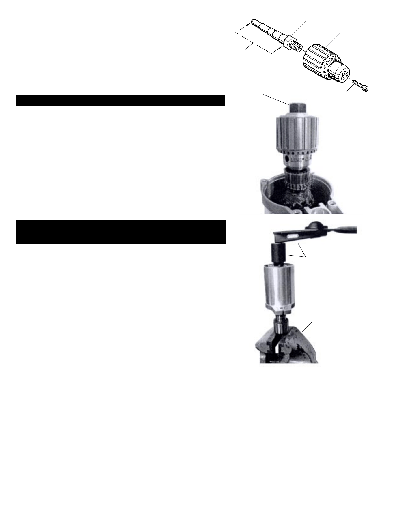
Repair instructions for the removal and installation
of Router Collet Shank No. 45-10-0080.
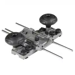
Removal or installation of the Collet Shank (fig. 46) for a 5615 Body Grip or 5619
D-Handle Router can best be accomplished by using a service tool fashioned
from a 1/2" drill reversing spindle, a reversing 1/2" 3 jaw chuck and a left hand
reversing spindle screw. Assemble the three pieces together; secure the
assembly together by applying Loctite
®
or an equivalent thread locking adhesive
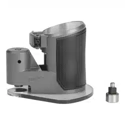
to the left hand screw. Optional, remove / cut the back end of the spindle off, as
pictured below, leaving only a 11/16" hex nut.
Removal of the Collet Shank from the Armature Shaft...
Step 1 Remove the rear commutator Ball Bearing (fig. 1) from the
Armature (fig. 13).
Step 2 Attach the '3-Jaw Chuck' service tool to the armature shaft, being
sure that the jaws grip the shaft beyond the ball bearing journal.
The jaws of the '3 Jaw Chuck' should be in contact with the back of
the armature commutator. To keep chuck jaws from spinning on
the shaft, tighten, turning chuck key in all three holes of the chuck
body.
CAUTION! Do not grip the rear ball bearing journal of the
armature shaft.
Step 3 Clamp the hex of the service tool securely into a vise.
Step 4 Use a 1-1/8" hex socket or box wrench on the hex of the collet
shank. Turn the collet shank counter-clockwise to remove.
Installation of the Collet Shank to the Armature Shaft...
torque specification of the Collet Shank to the armature shaft is
200 in-lbs / 16.5 ft-lbs (vigorously hand-tight)...
Step 1 Attach the '3 Jaw Chuck' service tool to the armature shaft as
described in step 2 above. Clamp the hex of the '3 Jaw Chuck'
service tool into a vise.
Step 2 Using a 1-1/8" hex socket and a in-lbs or ft-lbs torque wrench, turn
the 1-1/8" hex of the Collet Shank in a clockwise direction until tight
and the specified torque is reached.
The reverse is an optional method:
Clamp the 1-1/8" hex of the Collet Shank in a vise. Use an 11/16"
hex socket and torque wrench on the 11/16" hex of the '3 Jaw
Chuck' service tool to tighten the assembly to specification.
Reversing Spindle
1/2" Reversing
Chuck
L.H. Screw
Optional-
Cut off back end of
spindle, leaving the hex
and spindle threads.
11/16" hex
1-1/8" socket and
torque wrench
Vise