REVISED BULLETIN DATE
SERVICE PARTS LIST
BULLETIN NO.
WIRING INSTRUCTION
SERIAL
NUMBER
SPECIFY CATALOG NO. AND SERIAL NO. WHEN ORDERING PARTS
CATALOG NO.
58-01-0717
54-37-0225
5616-20/5616-29
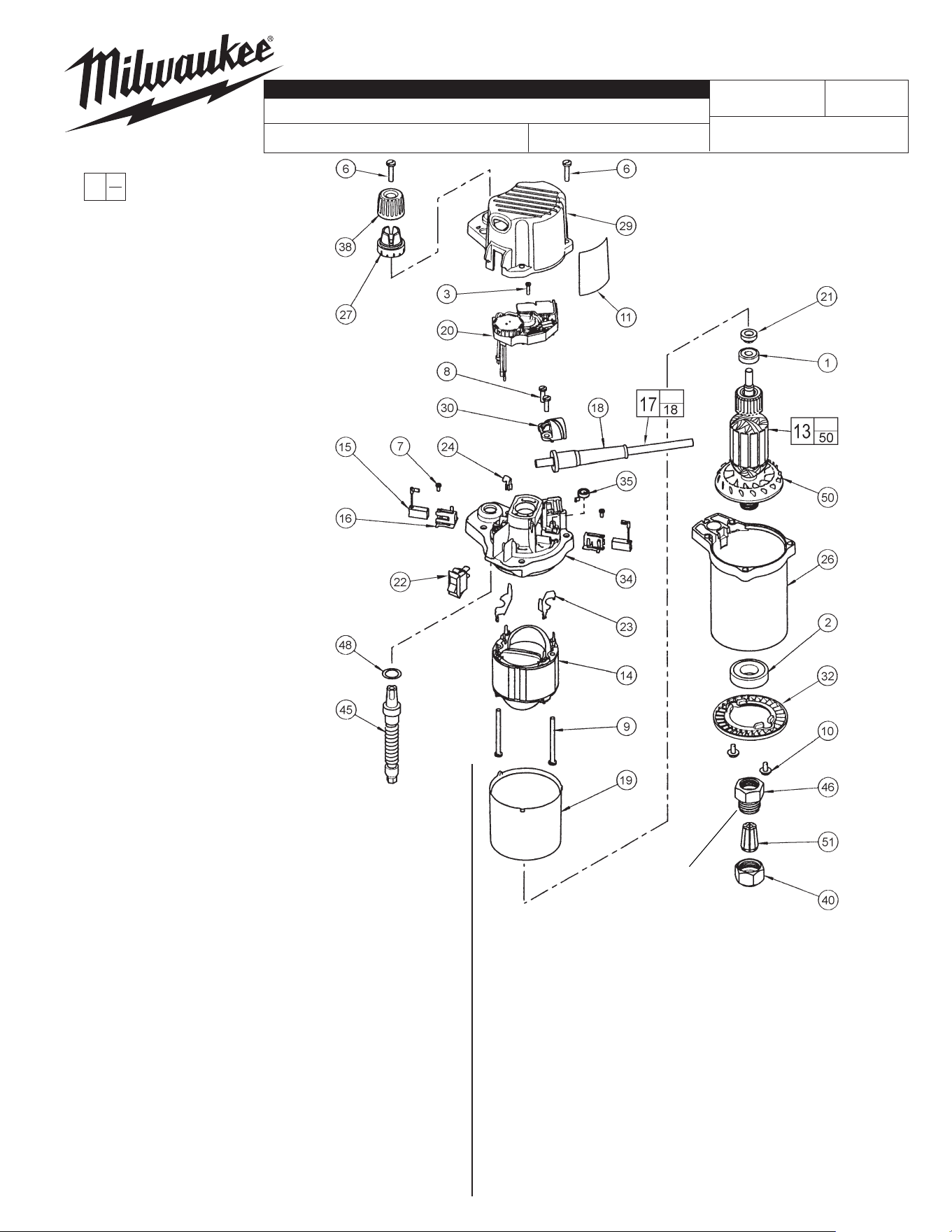
2.25 MAX. H.P. BODY GRIP ROUTER w/ ELECTRONICS
A19A
FIG. PART NO. DESCRIPTION OF PART QTY.
1 02-04-0852 Ball Bearing (1)
2 02-04-2006 Ball Bearing (1)
3 06-82-7225 4-20 x 1/2" Pan Hd. Plastite T-10 (1)
6 06-82-5574 10-24 x 7/8" Pan Hd. Slt. Tapt. T-25 (5)
7 06-82-7212 4-20 x 1/4" Pan Hd. Slt. Plast. T-10 (2)
8 06-82-7270 8-16 x 5/8" Pan Hd. Slt. Plast. T-20 (2)
9 06-82-7455 8-16 x 2-3/8" Pan Hd. Slt. Plast. T-20 (2)
11 12-20-0255 Service Nameplate Kit (1)
13 16-30-0015 Armature (1)
14 18-30-1015 Field (1)
15 22-16-0410 Carbon Brush (2)
16 22-22-0165 Brush Tube (2)
17 22-64-0320 Cord Set Assembly (1)
18 44-76-0210 Cord Protector (1)
19 23-16-0405 Field Insulator (1)
20 14-20-0055 Electronic Feedback Module (1)
21 23-38-0200 Tachometer (1)
22 23-66-2280 Rocker Switch (1)
23 23-74-0025 Field Terminal (2)
24 23-74-0055 Connector Terminal (1)
26 28-50-0105 Motor Housing (1)
27 31-01-0025 Depth Scale (1)
29 31-15-0095 Motor Cover (1)
30 31-17-0070 Cord Clamp (1)
32 31-55-0025 Contamination Shield (1)
34 31-50-0106 Motor Frame (1)
35 40-50-0190 Brush Spring (2)
38 43-98-0531 Depth Knob (1)
40 44-40-0095 Collet Nut (2 supplied with tool) (1)
45 45-08-0030 Depth Shaft Assembly (1)
46 45-10-0081 Collet Shank
(See reverse)
(1)
48 45-88-0045 Washer (1)
50 22-84-0380 Fan Assembly (1)
51 48-66-0985 1/4" Collet (1)
51 48-66-1010 1/2" Collet (1)
49-96-0365 1-1/8" Open End Wrench (Not Shown) (2)
49-96-0370
T-Handle Depth Adjustment Wrench (Not Shown)
(1)
See page 4
for collet shank
removal and
installation.
EXAMPLE:
Component Parts (Small #) Are Included
When Ordering The Assembly (Large #).
00
0
FIG. NOTES:
16,34,35 When servicing the motor frame (34) and the brush tube
(16) has to be removed, replace with a new brush tube.
Note: Make sure that the brush spring (35) is positioned
properly onto the new motor frame to insure proper brush
tension to the commutator.
21 Presstachometer(21)ush±.020totheendofthe
armature shaft (13). Conical side to the bearing (1).
40,51 Collet must be snapped into the collet nut prior to assembly
onto the collet shank.
June 2020
Router Motor Assembly
MILWAUKEE TOOL
l
www.milwaukeetool.com
13135 W. LISBON RD., BROOKFIELD, WI 53005
Drwg. 10
tab
48-10-5615
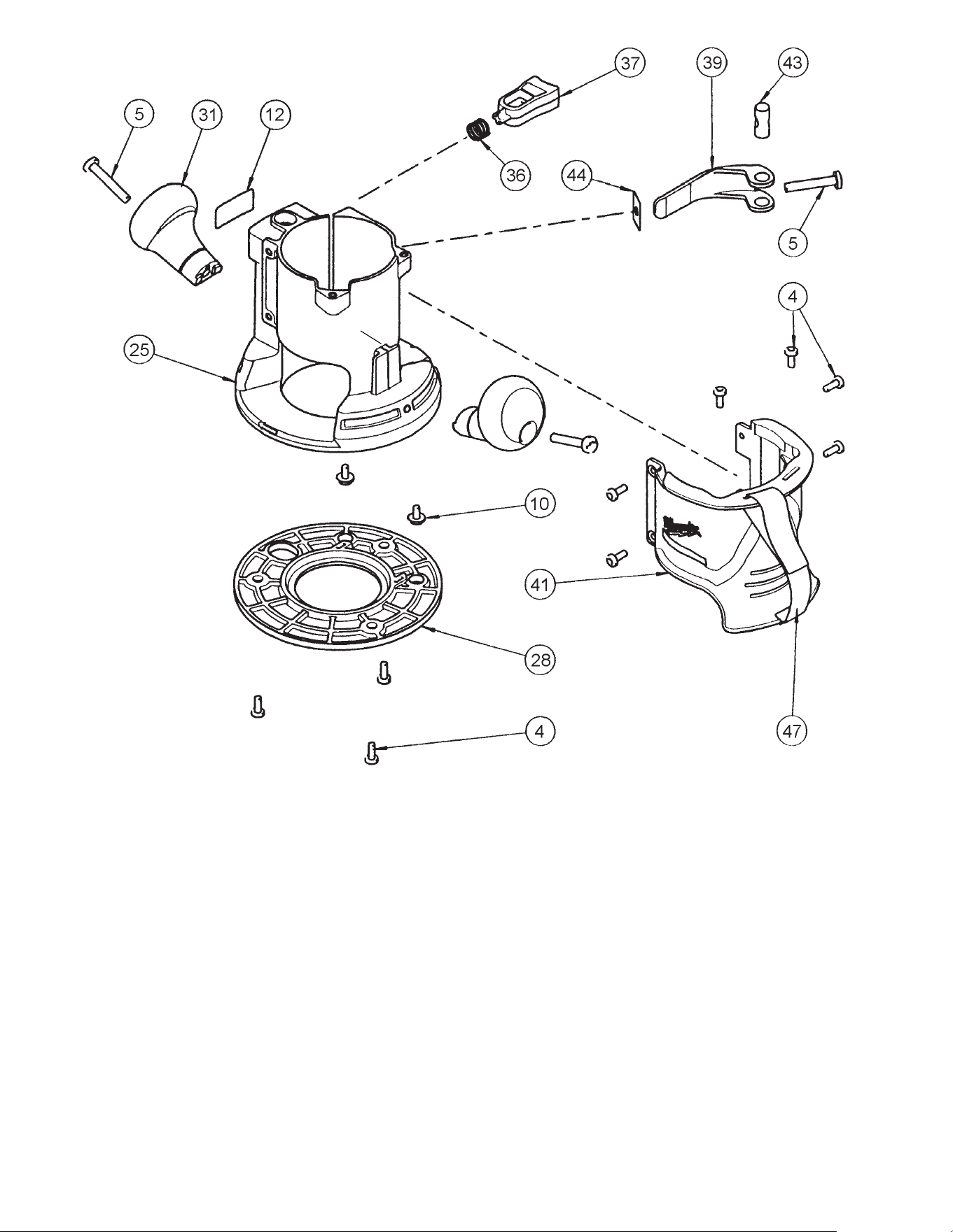
Router BodyGrip Assembly
FIG. PART NO. DESCRIPTION OF PART QTY.
4 06-82-5314 10-24 x 1/2" Slt. Pan Hd. Tapt. T-25 (9)
5 06-82-5514 1/4-20 x 1-1/2" Slt. Pan Hd. Tapt. T-30 (3)
10 06-82-8865 10-32 x 7/16" Pan Hd. Tapt. Sems T-25 (4)
12 12-25-0235 Nameplate (1)
25 26-06-0100 Base (1)
28 49-54-1045 Sub Base (1)
31 31-44-0130 Knob Handle (2)
36 40-50-4005 Compression Spring (1)
37 42-42-0126 Release Button (1)
39 44-10-0435 Base Clamp Lever (1)
41 44-52-0020 Body Grip (1)
43 44-60-0095 Thru Pin (1)
44 44-66-0035 Wear Plate (1)
47 45-56-0225 Handle Strap Assembly (1)
FIG. NOTES:
5,39 Clamping force for the base clamp lever (39) is adjusted with base clamp screw
(5). Tighten the screw using 10-20 lbs. force to close the lever to the locked posi-
tion. Motor unit must be in base when checking force.
25,36,37 To service the release button (37) and the compression spring (36) a long, thin
toollikeaatbladescrewdrivermustbeused.Fromthebottomofthebase(25),
insert the screwdriver into the cavity located under the release button. Press on
the button detent to release.
25,41,47 The metal clip from the handle strap (47) is to be placed around the tab on the
base (25). The body grip (41) is to be placed onto the base from the top so that
the cavity on the inside of the body grip slips over the tab on the base, securing
the handle strap.
39,43 Apply a thin coat of "L" grease, No. 49-08-4170, to the pivot surface areas of the
base clamp lever (39). Apply a thin coat of grease to the surface of the thru pin
(43).
43
40
13
44
29
14
33
45
37
26
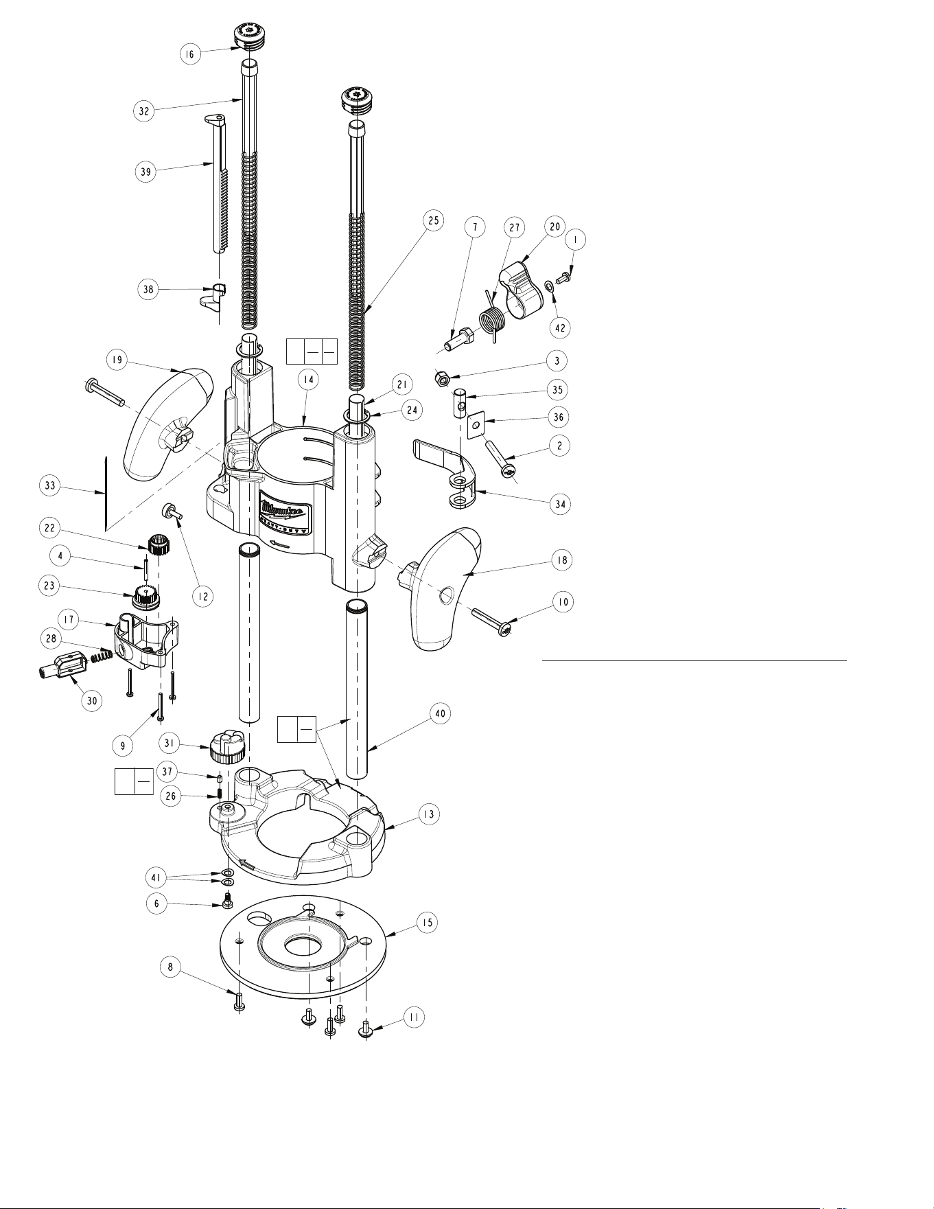
FIG. PART NO. DESCRIPTION OF PART QTY.
1 05-81-1005 Screw 8-32 x .394 T20 (1)
2 06-14-0080 Bolt 1/4-20 x 1.75 T30 (1)
3 06-57-6075 Lock Nut (1)
4 06-65-0700 Gear Pin (1)
6 06-75-0410 Shoulder Bolt M4 T25 (1)
7 06-81-1980 Plunge Lock Screw (1)
8 06-82-5314 10-24 x .5 Pan Tap Torx (3)
9 06-82-5315 Screw ST M3 x 26.5 mm T10 (3)
10 06-82-5514 T30, 1/4 - 20 x 1.50 Taptite (2)
11 06-82-8865 Slotted Torx Taptite Screw (2)
12 06-87-0100 Depth Rod Locking Screw (1)
13 --------------- Base (1)
14 --------------- Motor Carriage (1)
15 --------------- Subbase (See Chart) (1)
16 31-12-0380 Spring Cap (2)
17 31-40-0190 Gear Housing (1)
18 31-44-2530 Right Handle (1)
19 31-44-2535 Left Handle (1)
20 31-52-0120 Plunge Lock Lever (1)
21 31-55-0500 Spring Shield Tube (2)
22 32-40-2380 Gear with Hex (1)
23 32-40-2385 Gear with Screw (1)
24 34-60-3705 Retaining Ring (2)
25 40-50-1395 Plunge Spring (2)
26 --------------- Spring (1)
27 40-50-1410 Torsion Spring (1)
28 40-50-1415 Spring (1)
29 --------------- Bushing (not shown) (4)
30 42-42-1050 Gear Release Button (1)
31 42-46-0250 Turret (1)
32 43-56-0915 Spring Guide (2)
33 43-82-0175 Scale (1)
34 44-10-0435 Base Clamp Lever (1)
35 44-60-0095 Pin, Thru (1)
36 44-66-0035 Wear Plate (1)
37 --------------- Detent Pin (1)
38 44-72-0100 Depth Rod Pointer (1)
39 44-94-0460 Depth Stop Rod (1)
40 ---------------- Plunge Rod (2)
41 45-88-0995 Spring Washer (2)
42 05-90-0225 M4 Spring Washer (1)
43 14-46-5600 Base and Plunge Rod Kit (1)
44 14-46-5605 Motor Carriage Kit (1)
45 14-46-5610 Spring Assembly (1)
48-10-5600
Router Plunge
Base Assembly
WARNING! Spring Caps (16) are under pressure from Plunge Springs
(25) and could become projectiles when loosened. Use caution when
removing. Eye injury could occur. Always wear safety glasses.
Plunger Lock Screw (7) is LH Thread – tightens in counter-clockwise
direction
14,16, 25 Caution! Before removing Spring Caps (16) always release/bring
the Motor Carriage (14) to the upward most height setting to mini-
mize spring (25) tension.
14,16, 25 If the Plunge Springs (25) or Motor Carriage (14) need to be
serviced, remove Spring Caps (16) with a T-40 Tamper Proof style
driver. Note: Always cover / hold your hand over the spring caps
(16) when removing or installing springs (25). Always wear safety
glasses.
34, 35 Apply a thin coat of “L” grease, No. 49-08-4170, to the pivot
surface areas of the base clamp lever (34). Apply a thin coat of
grease to the surface of the thru pin (35).
14, 20, To aide in the removal of Retaining Rings (24) from the
24, 40 Plunger Rods (40). (springs (25) and plunger caps (16) removed
previously) Push Plunge Lock Lever (20) down and Lower Motor
Carriage (14) down until Retaining Rings (24) are just below the
internal Spring Cap threads inside the Motor Carriage.
The following sub-bases (15) are compatible with this base:
Cat. No. Outside dia. Center hole dia. Color
49-54-1027 6" 1-3/16" Clear
49-54-1028 6" 2-1/2" Clear
49-54-1045 6" 2-1/2" Black
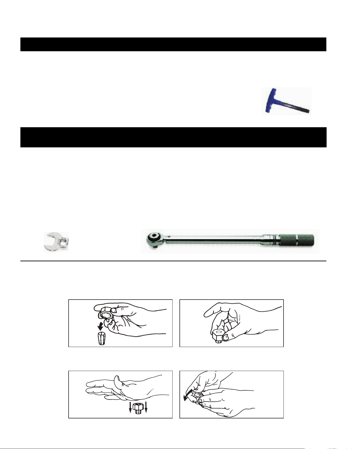
3/8” t-handle Hex Key
ft/lb Torque Wrench
1-1/8”
Crowfoot Wrench
To remove collet from nut, hold nut firmly with one
hand and press the collet to one side with the other
hand (Fig. 4).
Collets
The collet must be attached to the collet nut before it is put into the collet shaft. Be sure that the size of
the collet matches the size of the bit shank being used. If the wrong size bit shank is used, the collet
may break. For attaching or detaching the collet nut to the collet, follow the illustrated instructions.
Attaching Collet to Collet Nut
To assemble, place the narrow end of the collet
on an even surface. Take the nut and place it over
the collet (Fig. 1).
Position nut squarely over collet with the smaller
opening of the nut facing up (Fig. 2).
Snap nut and collet together by firmly applying
downward pressure into assembly with palm of
hand (Fig. 3).
Fig. 2
Fig. 3
Fig. 4
Fig. 1
Repair Instructions for the 5616-20,-29 2-1/4 H.P. Body Grip Router
45-10-0081 Collet Shank – removal / installation
Removal of the Collet Shank from the Armature shaft…
Note: The Armature shaft has a 3/8” internal hex; The Collet Shank threads onto the Armature shaft.
Step 1 applied at the time of assembly, mild heat to the Collet Shank will soften Loctite
®
Threadlocker and will aide in the
disassembly. Care should be taken with a heat gun, not to damage the seal of the Ball Bearing or Contamination Shield.
Step 2 to hold the Armature securely from turning, pass a 3/8” t-handle Hex Key through
the Collet Shank and into the Armature’s 3/8” internal hex.
Step 3 using the Router’s standard equipment Forged 1-1/8” Open End Wrench on the
external hex of the Collet Shank, turn the Collet Shank counter-clockwise to remove.
Installation of the Collet Shank to the Armature shaft…
torquespecification of the Collet shank to theArmature shaft is 16.5 ft-lbs [vigorously hand-tight]...
Installation of the Collet Shank [45-10-0081] for a 5616-20,-29 Body Grip Router can best be accomplished by using a
3/8” t-handle Hex Key, a 1-1/8” Crowfoot Wrench and a Torque Wrench.
Step 1 apply two drops of Loctite
®
‘Blue’ 242
®
or 243 Oil Tolerant, Threadlocker or equivalent, 180° apart, to threads of the
Armature shaft before threading the Collect Shank onto the Armature... care should be taken not to get thread locking
sealant on the ball bearing journal of the Armature shaft.
Step 2 pass a 3/8” t-handle Hex Key through the Collect Shank and into the Armature’s 3/8” internal hex to hold the Armature
securely from turning.
Step 3 using a 1-1/8” Crowfoot Wrench and a Torque Wrench combination turn the 1-1/8” hex of the Collet Shank in a clockwise
direction until tight and the specifiedminimum of 16.5 ft-lbs of torque is reached.