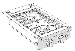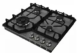
24” Gas Cooktop
Instruction Manual
Manuel d'instructions
Manual de instrucciones
Model/Modèle/Modelo:
FGHD4L2R-SS
* Picture shown here is for reference only.
2
English
Thank you for purchasing this Furrion
®
product. Before operating your new product, please read these instructions carefully.
This will ensure safe use and reduce the risk of injury. This instruction manual contains information for installation, maintenance
of the product and safe use.
Please keep this instruction manual in a safe place for future reference. Be sure to pass on this manual to any new owners of
this product.
The manufacturer does not accept responsibility for any damages due to not observing these instructions.
WARNING: If the information in this manual is not followed exactly, a fire or explosion
may result causing property damage, personal injury or death.
− Do not store or use gasoline or other flammable vapors and liquids in the vicinity of this or
any appliance.
− WHAT TO DO IF YOU SMELL GAS:
●
Do not try to light any appliances.
●
Do not touch any electrical switches.
●
Do not use any phone in your building.
●
Clear the building of all occupants.
●
Turn off the LP container valve or main container.
●
Immediately call your gas supplier from outside of your building for instructions.
●
If you cannot reach your gas supplier, call the fire department.
− Have the gas system checked and leakage source corrected by a qualified installer, service
agency, manufacturer, dealer or the gas supplier.
Table of Contents
Table of Contents .........................................................................................................................................................................2
Explanation of Symbols ..............................................................................................................................................................3
Important Safety Instructions ....................................................................................................................................................3
Product Overview ........................................................................................................................................................................5
Installation ....................................................................................................................................................................................6
What's in the Box .....................................................................................................................................................................................................................6
Tools You Will Need (Not Provided) ................................................................................................................................................................................6
Ventilating the Rooms ...........................................................................................................................................................................................................6
Location and Aeration .........................................................................................................................................................................................................7
Cut-out Preparation ...............................................................................................................................................................................................................7
Gas Connection ......................................................................................................................................................................................................................8
Leak Testing .............................................................................................................................................................................................................................. 8
Electrical Connection ........................................................................................................................................................................................................... 8
Operation.......................................................................................................................................................................................9
Changing NG to LPG ....................................................................................................................................................................10
Troubleshooting ...........................................................................................................................................................................13
Cleaning and Maintenance .........................................................................................................................................................13
Specifications...............................................................................................................................................................................14
CCD-0005859 Rev. 02.27.2023
3
English
Explanation of Symbols
This manual has safety information and instructions to help
you eliminate or reduce the risk of accidents and injuries.
Always respect all safety warnings identified with these
symbols. A signal word will identify safety messages and
property damage messages, and will indicate the degree or
level of hazard seriousness.
DANGER
Indicates an imminently hazardous situation which, if not
avoided, will result in death or serious injury.
WARNING
Indicates a potentially hazardous situation which, if not
avoided, could result in death or serious injury.
CAUTION
Indicates a potentially hazardous situation which, if not
avoided, may result in minor or moderate personal injury, or
property damage.
Important Safety Instructions
Before installing and using this new appliance which is easy
to operate though, it is important to read this Instruction
Manual through carefully. It provides information for a safe
installation, use and maintenance. Keep this Instruction
Manual in a safe place for future reference.
NOTE: The pictures shown in the figures in this Instruction
Manual are purely indicative.
DANGER
● The installation of all-gas and combination appliances
must comply with the National Standards in force.
● The appliance must only be used for what it has been
made for: “Cooking for Residential Use Only!” Any
other uses are considered as improper and dangerous.
● A separate circuit serving only the appliance is
recommended. And use sockets that cannot be turned
off by a switch or pull chain.
● Never clean any parts of the appliance with flammable
fluids, fumes of which can cause hazards of fire or
explosion.
● Do not store or use gasoline or other flammable vapors
and liquids in the vicinity of this or any other appliances,
fumes of which can cause hazards of fire or explosion.
● Unplug the appliance from socket or disconnect power
source before cleaning or maintaining it, otherwise
electrical shock or even death may be caused.
● Electrical grounding instructions - the appliance must
be installed and grounded by a qualified technician in
accordance with the National Electrical Code ANSI/
NFPA No. 70 (Latest Edition) and local electrical code
requirements.
● Do not carry out cleaning or maintenance operations on
the appliance unless its power supply is totally shut off.
● If the supply cord is damaged, it must be replaced by the
manufacturer or its service agent or a similarly qualified
personnel in order to avoid a hazard.
● If you are using a socket near the appliance make sure
that the cables of electrical appliances you are using do
not touch and are far enough away from all hot parts of
the appliance.
● To prevent appliance damage, short circuit, electric
shock or any other possible hazards, the installation,
maintenance and repair should ONLY be carried out
by qualified personnel. DO NOT attempt to repair the
appliance by yourself!
DANGER
Important Precautions and Recommendations for Use
of Electrical Appliances:
● Use of any electrical appliance must follow a series of
fundamental rules. In particular:
● Never touch the appliance with wet hands or feet;
● Do not operate the appliance barefooted;
Electrical Grounding Instructions:
● FOR PERSONAL SAFETY, THIS APPLIANCE MUST
BE PROPERLY GROUNDED.
● This appliance is equipped with a three-prong
grounding plug for your protection against shock hazard
and should be plugged directly into a properly grounded
socket. Do not cut or remove the grounding prong from
the plug.
● Do not under any circumstances cut or remove the
third (ground) prong from the power plug. Electrical
installation should comply with national and local
codes.
WARNING
● The installation adjustments, conversions and
maintenance of the gas cooktop must be carried
out by qualified personnels. Improper installation,
adjustments, alterations, services or maintenance can
result in property damage, personal injury or death.
For any problems or doubts, please consult a qualified
personnel, service agency or gas supplier.
● Keep cooktop area clear and free from combustible
materials, gasoline, and other flammable vapors and
liquids.
● NEVER use this appliance as a space heater to heat or
warm the room. Doing so may result in carbon monoxide
poisoning and overheating of the appliance.
CCD-0005859 Rev. 02.27.2023
4
English
WARNING
● When the burners or plates are in use do not leave them
unattended and make sure there are no small children
in the vicinity. Check that pan handles are positioned
correctly and always keep an eye on the pan whenever
oils or fats are used as they are easily inflammable. Do
not use spray cans near the appliance when it is in use.
● If the built-in Cooktop has a lid, before opening the lid
remove any food deposits from its surface.
● If the built-in Cooktop has a crystal glass lid, it can
explode if heated. Turn in “OFF” position all the burners
(full disk symbol on control panel) and switch off all
plates; let the Cooktop become cool before closing the
lid.
● If you see any cracks on the surface of the plate,
disconnect the appliance from the mains immediately.
● After you have used the appliance make sure that all
the controls are in “OFF” position (full disk symbol on
control panel).
● Carry out the connection avoiding all kinds of stress to
the appliance.
● This appliance is not intended for use by persons
(including children) with reduced physical, sensory
or mental capabilities, or lack of experience and
knowledge, unless they have been given supervision or
instruction concerning use of the appliance by a person
responsible for their safety.
● Children should be supervised to ensure that they do
not play with the appliance.
● Do not store items of interest to children in the cabinets
above the cooktop. Children should not be left alone or
unattended in the area where appliance is in use.
● Do not allow children to climb or play around the
cooktop. They should never be allowed to sit or stand
on any part of the appliance. Children climbing on the
cooktop to reach items could be seriously injured.
CAUTION
● When you have finished using the appliance check
that all the controls are in the off or closed position and
Furrion logo of the knob corresponds to the OFF
serigraphy on the front panel.
● Do not wear loose-fitting or hanging garments while
using the appliance. Do not let clothing or other
flammable materials contact hot surfaces.
● Do not heat unopened food containers. Buildup of
pressure may cause the container to burst and result in
injury.
● Do not use aluminum foil to line any part of the cooktop,
use aluminum foil only to cover food during cooking.
Improper installation of these liners may result in risk of
electric shock, or fire.
● Utensil handles should be turned inward and not extend
over adjacent surface burners. To reduce the risk of
burns, ignition of flammable materials, and spillage due
to unintentional contact with the utensil, the handle
of the utensil should be positioned so that it is turned
inward, and does not extend over adjacent surface
burners.
● When heating fat or grease, watch it carefully. Fat or
grease may cause fire if heated too hot.
● Smother grease fires with a pan lid, or use baking soda,
a dry chemical or foam-type extinguisher.
IMPORTANT
This cooktop is factory set for use with NG (Natural Gas).
If you wish to use LPG (Liquid Propane), call a licensed
professional to install the LPG conversion kit (included).
Save these instructions for future reference!
CCD-0005859 Rev. 02.27.2023
5
English
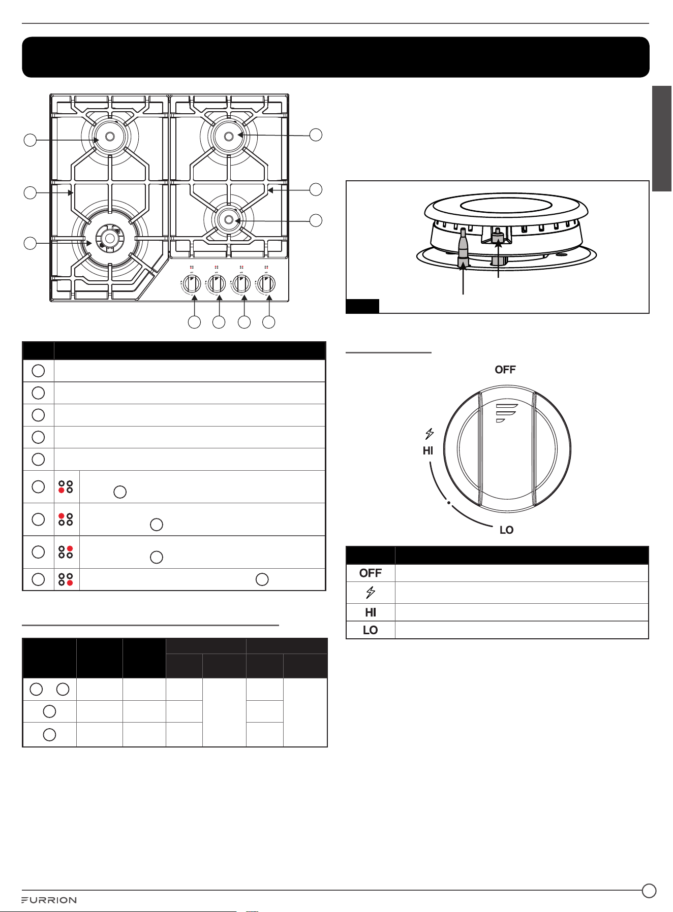
Product Overview
1
5
4
6 7 8 9
3
5
2
Item Part Name
1
Rear Left Semi-Rapid gas burners (SR)
2
Right Semi-Rapid gas burners (SR)
3
Auxiliary gas burner (Aux)
4
Wok burner
5
Grate
6
Burner adjustment for Auxiliary gas burner
(Aux)
3
7
Burner adjustment for Left Semi-Rapid gas
burners (SR)
1
8
Burner adjustment for Right Semi-Rapid gas
burners (SR)
2
9
Burner adjustment for Wok burner
4
Burner Nozzles and Power Output Table
Burner
Position
Max.
Output
(Btu)
Min.
Output
(Btu)
NG LPG
Nozzle
D (mm)
Pressure
(W.C.)
Nozzle
D (mm)
Pressure
(W.C.)
1
&
2
Max: 6,000 Min: 1,560 1.18
4"
0.75
11"
3
Max: 3,400 Min: 930 0.88 0.57
4
Max:
12,000
Min: 3,820 1.8 1.05
● The burners are graduated in their size and rating to
provide the exact heat required for every style of cooking.
● The burners can be equipped with Flame Safety Device
(FSD = Thermocouple Fig. 5).
● On the top of each knob there is a printed diagram
showing to which burner or heating element it refers.
Thermocouple
Spark igniter
Fig. 5
Control Knob
Item Description
OFF position (full disk)
Ignite
Maximum position (big flame)
Minimum position (little flame)
CCD-0005859 Rev. 02.27.2023
6
English
Installation
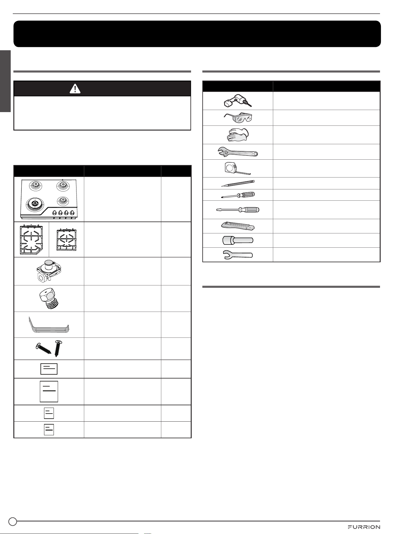
What's in the Box
CAUTION
The packaging materials used (cardboard, bags,
polystyrene foam, nails …) should not be left anywhere
within easy reach of children as they are a potential hazard
source.
Make sure you have the following listed items included in the
packaging. If any item is damaged or missing, contact your
dealer.
Part Description Quantity
Main Body 1
Cooking Grates 2
Regulator 1
Nozzles for LPG 4
Clamping Brackets 4
Screws: M4 x 10mm-For
Clamping Brackets
4
Conversion Label 1
Instruction Manual 1
Warranty Leaflet 1
Conversion Kit 1
Tools You Will Need (Not Provided)
Part Description
Electric drill (Bit size: 3mm)
Safety goggles
Gloves
Adjustable wrench
Tape measure
Pencil
Phillips screwdriver
Flat Blade
(2mm width and 5mm hight)
Cutting knife
7mm nut sleeve
7mm nut driver
Ventilating the Rooms
● The room where the appliance is installed must be
permanently ventilated so as to guarantee correct
functioning according to the National Rules in force.
The quantity of air needed is that required for a regular
combustion of the gas and for the ventilation of the room
and whose volume must be no less than 706.3 cu. ft . The
natural flow of air must be directly through permanent
openings in the walls (that go through to the outside)
of the room to be ventilated with a minimum cross free
section of 15.5 sq.in for appliance fitted with the Flame
Safety Device (FSD) on each burner (see A of Fig. 1).
These openings must be positioned so they cannot be
never obstructed.
● Indirect ventilation is also allowed by taking air from
rooms adjacent to the one to be ventilated, strictly
complying with the prescriptions of the National Rules in
force.
CCD-0005859 Rev. 02.27.2023
7
English
Location and Aeration
● Gas appliances must always discharge the products of
combustion through extractors connected to flues or
directly to the outside (see B of Fig.1). If it is impossible to
use an extractor, a fan installed on the window or on a wall
facing the outside is allowed and should be switched on
every time the appliance is used (see B of Fig.1), provided
the rules and regulations in force relating to ventilation.
● (*) Air inlet - minimum section 15.5 sq. in.
WARNING
● When a gas appliance is being used it produces heat
and humidity in the room where it is installed. For this
reason the room must be well ventilated, keep the
natural ventilation openings free (fig. 6) and switch
on the mechanical aeration system (suction hood or
electric fan (see B and C of Fig. 1).
● If the cooker is used for a long time, additional aeration
may be necessary, for instance, opening a window, or a
more effective aeration by increasing the power of the
mechanical system if there is one.
(*)
A
(*)
B
(*)
C
Fig. 1
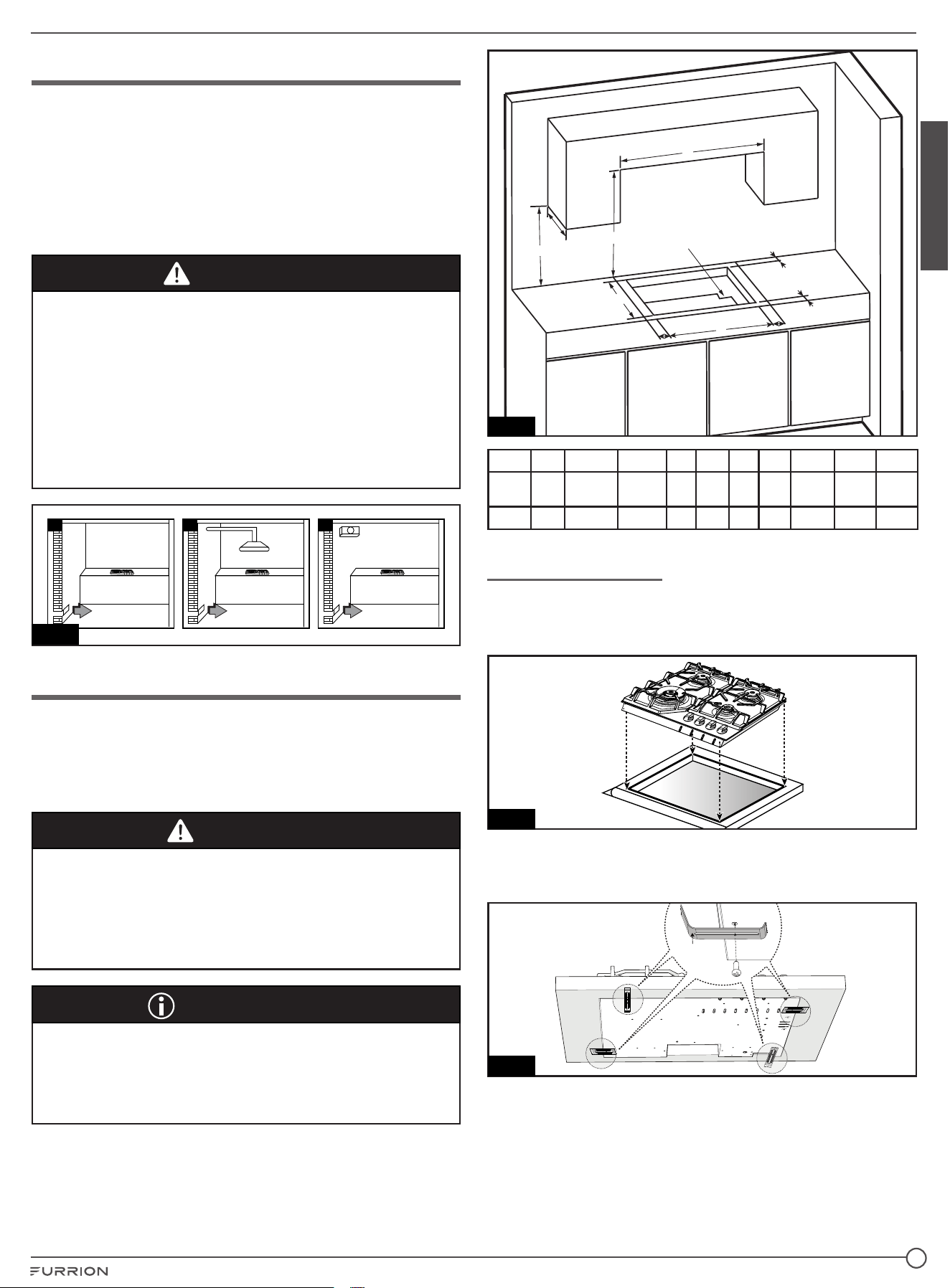
Cut-out Preparation
The measurements of the cavity made in the top of the
modular cabinet and into which the Cooktop will be recessed
are indicated in Fig. 2. Cupboards or hoods have to maintain
a least distance of 30 inches from the top (see dimension C
in Fig. 2).
CAUTION
CLEARANCE TO COMBUSTIBLE CONSTRUCTION:
A Minimum of 4½" (114mm) from the sides (see D and E
dimension in Fig. 2) and a minimum of 2½" (64mm) from the
front and back (see G and F dimension in Fig. 2) must be
maintained from the cooktop above and below the cooking
surface to adjacent vertical combustible construction.
IMPORTANT
Under the Cooktop it is necessary to always apply a panel
of separation in wood, positioned to a least distance of 2¾
inches by the bottom of the same, which has to easily be
removable to allow possible operations of maintenance
(Fig. 2)
H
C
J
D
E
G
I
A
B
F
4”x8”(102mm x 203mm)
opening to route armored
cable if panel is present
Fig. 2
UNIT A B C D E F G H I J
inch 18 Max. 13 Min. 30 4½ 4½ 2½ 2½
Min.
23
2111/16 2113/16
mm 457 330 762 114 114 64 64 590 551 478
Fixing the Cooktop
1. Place the cooktop in the worktop cut-out, making sure it is
central. Press down on the sides of the gas cooktop until it
is resting fully on the cut-out edges.(Fig. 3)
Fig. 3
2. Insert the clamping brackets into their relative housings
on the Cooktop. Lock then in place with the screws
M4 x 10mm. (Fig. 4)
ClampingBracket
Fig. 4
CCD-0005859 Rev. 02.27.2023
8
English
Gas Connection
FOLLOW ALL APPLICABLE STATE AND LOCAL CODES:
ANSI/CSA standard code:"ANSI Z 21.1/CSA 1.1-2016".
Household cooking gas appliance.
WARNING
● Before to connect the appliance to the gas network,
check that the adjustment sticker data plate is put on
the bottom of the appliance and is corresponded to the
available one in the gas network.
● The adjustment sticker data plate, gives all the
appliance’s setting conditions as: gas type and gas
operating pressures.
● Once installed, check there are no leaks by using a
soapy solution only. Never use a flame! It is forbidden!
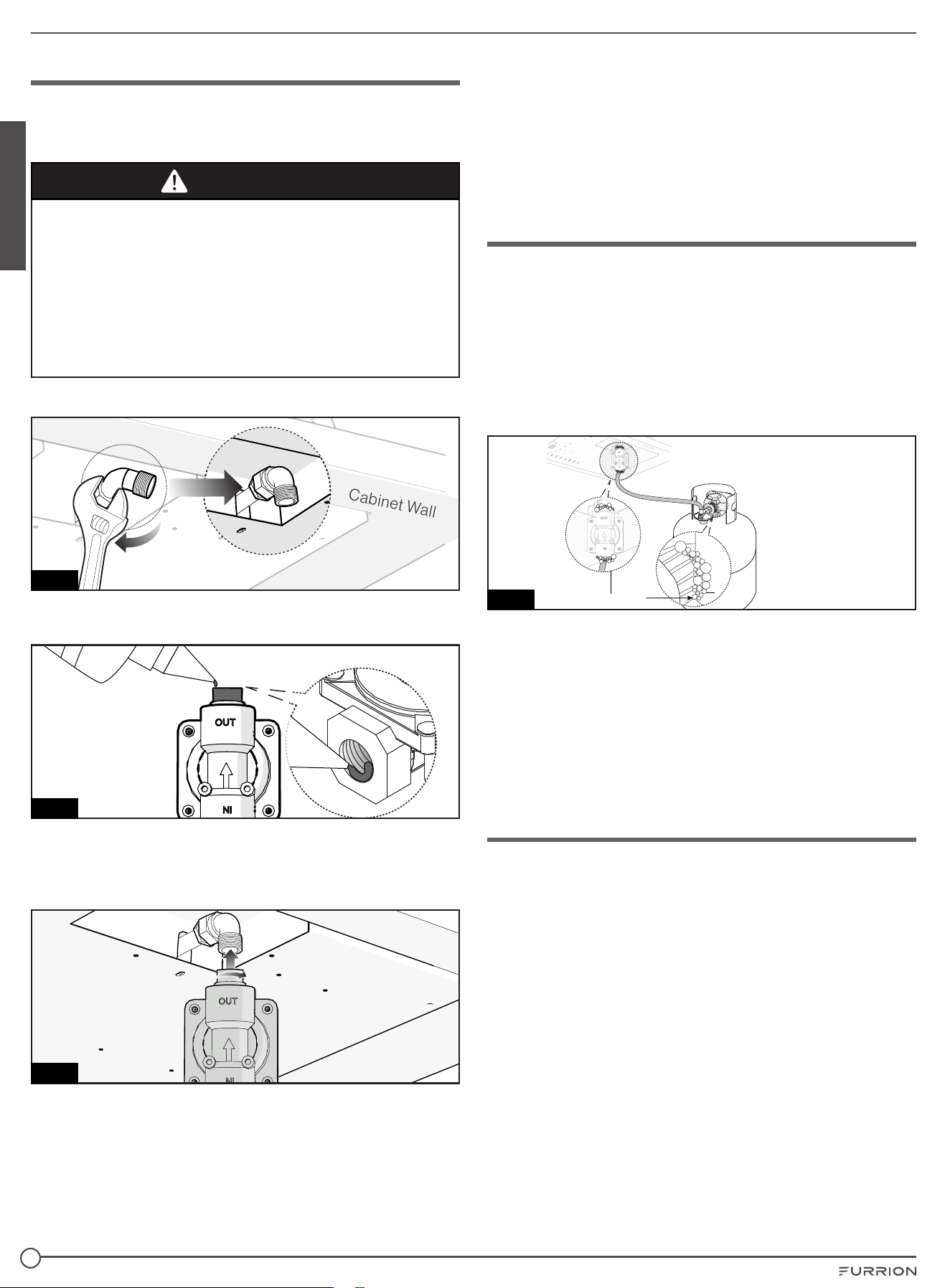
1. Rotate the L-elbow 90° by clockwise as shown in Fig. 5.
Cabinet Wall
Fig. 5
2. Fill in the anaerobic glue-262 (not provided) into the OUT
direction of the regulator around to the thread. (Fig. 6)
A
na
e
r
o
b
i
c
Gl
u
e
262
A
na
e
r
o
b
i
c
Gl
u
e
262
Fig. 6
3. Insert the regulator into the L-elbow twist around in able
to the anaerobic glue-262 fill in the thread symmetrically.
Fix the regulator into the L-elbow by vertical downwards.
(Fig. 7)
Fig. 7
4. Install the gas supply hose with ½" connection (not
provided). This cooktop is fitted with a threaded ½" female
regulator. For installation use copper pipe and CSA or UL
certified connectors which conform to USA and Canadian
safety standards. Ensure when cooktop is installed the
flexible gas supply pipe cannot touch any moving parts.
Make sure adequate space is available so the supply pipe
will not be bent or damage after installation.
Leak Testing
1. Turn all burner control knobs to OFF position.
2. Be sure hose is tightly connected to the LP tank.
3. Completely open the LP tank valve by turning cylinder
valve knob counterclockwise (right to left). If you hear a
rushing sound, turn gas off immediately. There is a major
leak at the connection. Correct before proceeding by
calling franchiser for replacement parts.
4. Brush soapy solution onto areas where bubbles are
shown in LP tank. (Fig. 8)
Bubble
Cabi net Wal l
Ca bin et Wall
Fig. 8
5. If “growing” bubbles appear, there is a leaks. Close LP
tank valve immediately and retighten connections. If leaks
cannot be stopped do not try to repair. Call franchiser for
replacement.
6. Always close LP tank valve after performing leak test by
turning cylinder valve knob clockwise.
NOTE: When leak testing this appliance, make sure to test
and tighten all loose connections. A slight leak in the system
can result in a low flame, or a hazardous condition.
Electrical Connection
1. The electrical connection must be carried out in
accordance with the current standards and laws in force.
2. Plug the power cord from the appliance into a dedicated
15 amp electrical outlet.
CCD-0005859 Rev. 02.27.2023
9
English
Operation
WARNING
DO NOT TOUCH THE COOKTOP SURFACE, BURNERS,
GRATES OR ANY AREAS NEAR THEM DURING OR
AFTER JUST END OF USE.
The burners and grates remains very hot for a while even
though the cooktop had been turned off. During or after use,
do not touch or let clothing or other flammable materials
touch these areas until they have had sufficient time to cool
down.
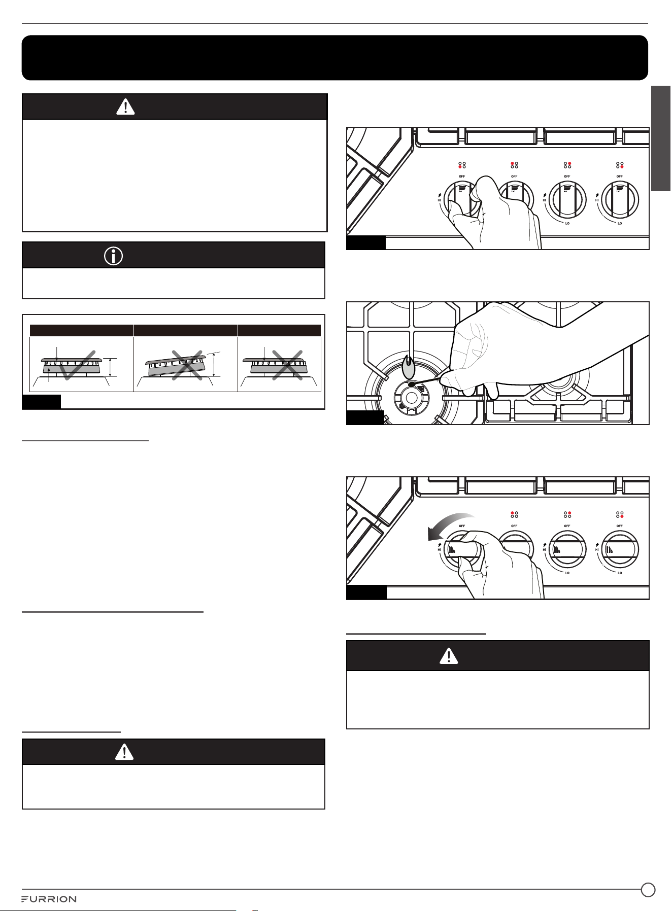
IMPORTANT
Check the burner cap and burner base if in the position
corresponding. (Fig. 9)
Burner Cap
parallel
Burner Base
Correct
Burner Cap Not Central
Incorrect
Angled
Incorrect
Fig. 9
Lighting Instruction
1. Press and turn anticlockwise the knob corresponding to
the burner you wish to use from “OFF” position (full disk
symbol on control panel), until it reaches the “HI” position
corresponding to the big flame and place a lighted match
close to the burner.
2. After ignition, turn the handle from “HI” position
(corresponding to the big flame) to “LO” position
(corresponding to the little flame) and check stability
flame. To turn “OFF” the burner, turn clockwise the handle
up to “OFF” position (full disk symbol on control panel).
If the Burner Does not Ignite
In the event of failure to light the burner within 5 seconds,
immediately turn the control knob clockwise to the OFF
position. Wait at least 5 minutes and repeat the igniting
procedure. If ignition still not occur, use a gas lighter or a
match to light the burner. Refer to the ‘Manual Ignition’
section.
Manual Ignition
WARNING
Use care when lighting the burners by hand. If a burner
lights unexpectedly, or your hand is to close to the burner,
you could be burned.
In the event of failure to ignite the burner in standard ignition,
you may light the burner manually by following the steps
below:
1. Turn the appropriate burner control knob
counterclockwise to the OFF position. (Fig. 10)
Fig. 10
2. Press and turn the control knob to HI position.
3. Immediately strike and place a burning long wooden
match or a gas lighter near the burner to light. (Fig. 11)
Fig. 11
4. Repeat steps 1 to 2 to light the other burner(s) as required.
5. Rotate the burner control knob to adjust the flame to
desired level. (Fig. 12)
Fig. 12
If the Flame Goes Out
WARNING
Risk of Fire!
If the flame goes out accidentally, gas will escape. Never
leave the gas burner unattended during operation. Ensure
that there are no drafts that can affect the burner flame.
Immediately turn the control knob to OFF position. Wait at
least 5 minutes and light the burner again.
CCD-0005859 Rev. 02.27.2023
10
English
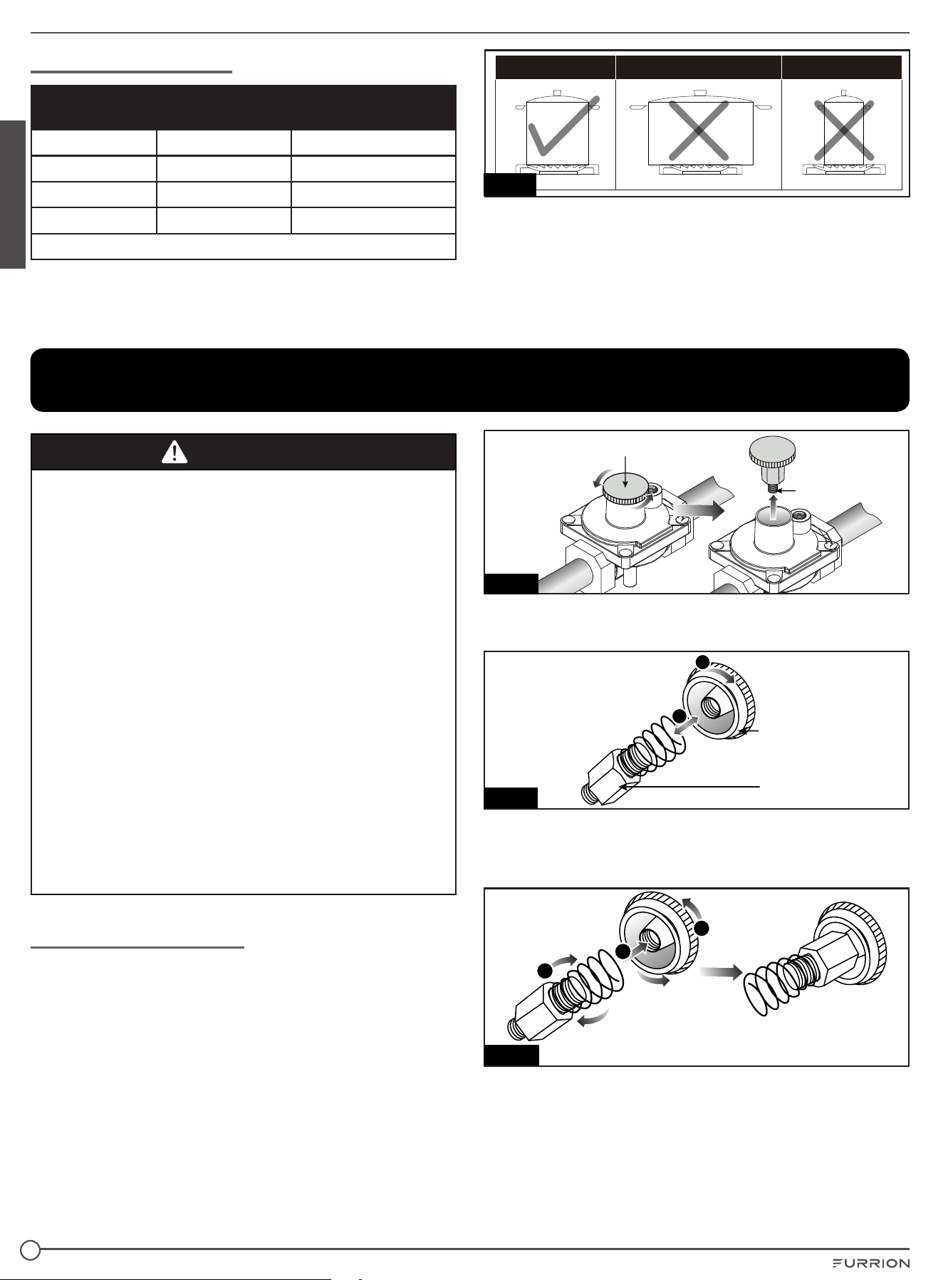
Suitable Pans (Fig. 13)
Diameters of pans which may be used on the top
burners
Burner Minimum Maximum
Auxiliary 4” 23/32 (12 cm) 5” ½ (14 cm)
Semirapid 6” 19/64 (16 cm) 9” 7/16 (24 cm)
Rapid 9” 7/16 (24 cm) 10” 15/64 (26 cm)
NOTE: Do not use pans with concave or convex bases.
Ye s No No
Fig. 13
Please refer to above table to choose the most suitable burner
according to the diameter and volume capacity of the container.
A suitable size of pots or pans matching with a suitable burner could
take full use of the heating efficiency of the burner and avoid the
waste of gas fuel.
Put a small size pot or pan on a larger size burner does not
mean that the boiling speed will be faster.
Changing NG to LPG
WARNING
● Check the adjustment of the appliance, before to make any
adjusting operation, having a look on proper adjustment
sticker data plate, put on the bottom of the appliance.
● Before any adjustment is attempted, which may be
necessary when installing for the first time or when
converting gas type, pull the plug off the mains socket.
● When the adjustment or preadjustment has been made, a
technician must do any re-sealing, if any.
● To adjust “reduce rate”, using proper screw driver, from
Natural gas to Butane/Propane ones, light burners one
by one and put handle in minimum position; remove the
handle and screw clockwise completely the by-pass screw.
Put back in position the handle and check stability of flame,
turning the handle from “Maximum” to “Minimum” position
and vice-versa.
● To adjust “reduce rate”, using proper screw driver, from
Butane/Propane gases to Natural one, light burners one
by one and put handle in minimum position; remove the
handle and unscrew anticlockwise in the way to get proper
flame. Put back in position the handle and check stability
flame, turning the handle from “Maximum” to “Minimum”
position and vice-versa.
● “Primary air adjustment” on Cooktop gas burners is
unnecessary.
Adjusting the Regulator
1. Disconnect all electrical power at the main circuit breaker
or fuse box.
2. Shut off the gas supply to the cooktop by closing the
manual shut-off valve.
3. Adjust the pressure regulator by following below
instructions:
− Unscrew the regulator cap with the wrench by
anticlockwise, then remove it from regulator by vertical
direction. (Fig. 14)
NOTE: When user purchase this appliance, the
regulator pin for NG by default.
Regulator Cap
Retainer pin for NG
Fig. 14
− Rotate the retainer pin by anticlockwise to remove the
spring. (Fig. 15)
Spring
Retainer Pin
a
b
Fig. 15
− To convert gas supply from NG to LP gas, reverse the
retainer pin and spring, and put back tightly into the
regulator cap by clockwise. (Fig. 16)
Regulator pin for LP gas
a
c
b
Fig. 16
CCD-0005859 Rev. 02.27.2023
11
English
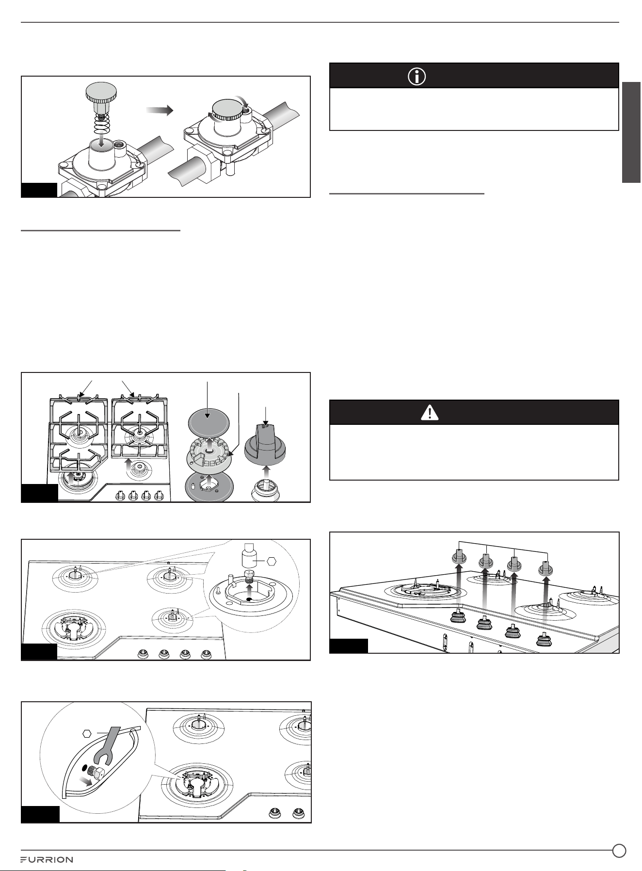
− Insert the regulator cap and screw the back into the
regulator by clockwise and re-attach the regulator to
the nipple and flare union. (Fig. 17)
Fig. 17
Changing Burner Nozzles
Before change the burner nozzles, disconnect all electrical
power at the main circuit breaker or fuse box. Shut off the gas
supply to the cooktop.
INSTALLATION TIP: First remove all nozzles and then start
replacing them. This will help to prevent the possibility that
some may not be replaced.
1. Remove the burner grates, burner caps and knobs.
(Fig. 18)
NOTE: Pay attention to replace the burner base and
burner cap corresponding. (Fig. 9 on page 9)
Burner Cap
Burner Base
Burner Grate
Knob
Fig. 18
2. Use a 7mm nut sleeve to remove the below 3 burner
nozzles. (Fig. 19)
7
Fig. 19
3. Use a 7mm nut driver to remove the below burner nozzle.
(Fig. 20)
7
Fig. 20
4. Install the proper nozzles tightly in the exact locations as
shown above.
IMPORTANT
Carefully read and observe each nozzle label for correct
location. (Refer the section of Burner Nozzles and Power
Output Table on page 5.)
5. It should test each burner’s leakage one by one to make
sure the nozzles are fixed tightly.
Adjusting Burner Flames
● The burners can be adapted to different types of gas by
simply installing the injectors suitable for the gas you want
to use. The burner nozzles can be fitted with the appliance
or available in an authorized Assistance Centre.
● To do this, first remove the burner cups and with a socket
spanner, unscrew injectors using proper tool and replace
them with injectors corresponding to the new adjustment
gas type. Always tightly lock the injector in place,
without adding any material on the injectors threads: It is
forbidden!
● To help the installer there is a table on page 4 giving
nominal heat inputs, injector diameter and operating
pressures of the different gas types. For best
comprehension, each injector is marked on its body with
proper diameter.
CAUTION
After the burner nozzles have been changed, the
technician must adjust the burners as described in the
previous paragraphs, seal any adjustment or preadjustment
parts.
1. Light the burner and turn the knob to reduced rate
position (small flame). Remove the knobs which are
simply inserted onto tap stem. (Fig. 21)
Knobs
Fig. 21
CCD-0005859 Rev. 02.27.2023
12
English
2. Using a flat blade (2mm width and 5mm hight) to the
screw as shown, turn clockwise is for smaller fire, turn
counterclockwise is for bigger fire. Then check the fire of
each burner one by one. (Fig. 22)
NOTE:
− Make sure that when turning quickly from “Maximum”
position to “Minimum” one, the burner does not
extinguish.
− If the tap, after long use of the Cooktop, presents
some friction to rotation, do not insist to use it. Call
the nearest Assistance Centre of Furrion that will
take action to substitute the tap with the proper
one.
Flat Blade
(2mm width and 5mm hight)
Ta p
Fig. 22
− Put the burner cap and head back to the burner base.
The burner cap and head should seat well into the
burner base before testing.
− After the burner seats well, turn the burner on HI setting
and check the flames. They should be blue in color and
may have some yellow tipping at the ends of the flame
when using LP gas. Foreign particles in the gas line
may cause an orange flame at first, but this will soon
disappear.
− Then turn the knob from HI to LO setting:
If the flames are too small or extinguished, open the
valve more than the original setting until the fire will not
extinguish.
If the flames are too large, close the valve more than
the original setting.
− Each burner to specific knob when testing (Refer
section of Product Overview on page 5 to find the
knob adjust the corresponding burner.
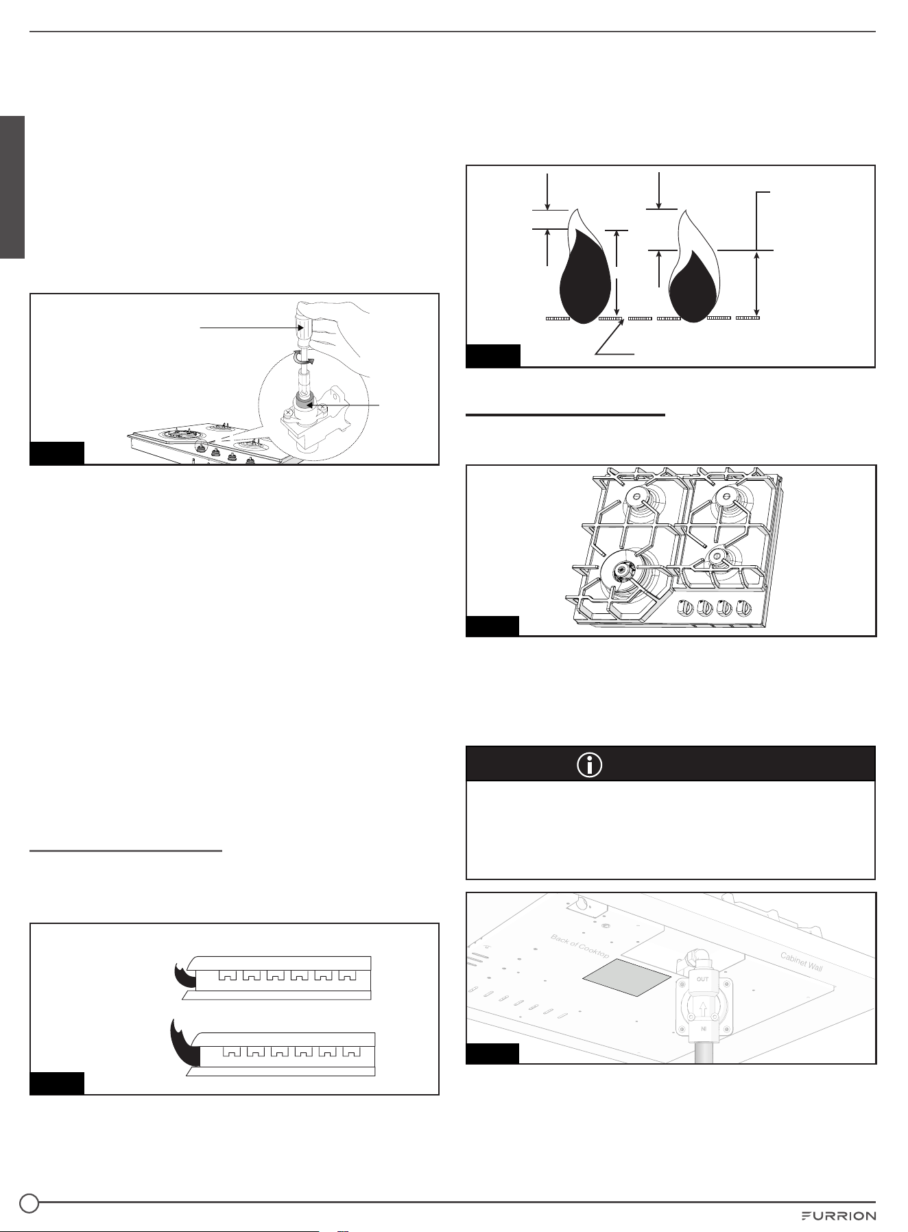
Check Burner Flames
Adjust the height of surface burner flames. The surface
burner low flame should be a steady blue flame
approximately ¼" (6.4 mm) high. (Fig. 23)
Good
Blue
Blue
Low flame
High flame
Bad
Yellow
Yellow
Holes in Burner
Fig. 23
Visually check burner flames. Burner flames should be blue
and stable with no yellow tips, excessive noise, or lifting.
Some yellow tips on flames up to 1” (25.4mm) in length are
acceptable as long as no carbon of soot deposit appear. If
any of these conditions exist call our customer service line.
(Fig. 24)
Good
Blue
Blue
Low flame
High flame
Bad
Yellow
Yellow
Holes in Burner
Fig. 24
Testing Flame Stability
After adjusting the burners, assemble the seat the burners
and grates and knobs well as below: (Fig. 25)
Fig. 25
After the re-assembly is made, turn all burners off. Ignite each
burner individually. Observe the flame when the control knob
is at the "HI" position. Rotate the knob to the lowest setting
and be sure that the flame size decreases as the knob is
rotated counter-clockwise.
IMPORTANT
After the conversion, substitute the Conversion Label
(included) put on the bottom of the appliance with the new
one, corresponding to the new gas adjustment. Affix the
Conversion Label as close as possible to the conversion
plate appliance on the appliance. (Fig. 26)
Cabinet Wall
Ba ck of Coo ktop
Co nvens ion La bel
Fig. 26
CCD-0005859 Rev. 02.27.2023
13
English
Troubleshooting
Some of the problems can be caused by simple maintenance operations or something that was forgotten and can easily be
resolved without having to call for technical assistance.
Problem Solution
If your appliance is not
working efficiently
● Make sure the gas cock is open.
● Check the plug is in.
● Check that the knobs are set correctly for cooking and then repeat the operations given in
the Instruction Manual.
● Check the electrical system safety switches (RCD). If there is failure in the system call an
electrician.
Cleaning and Maintenance
Clean the appliance regularly to keep all parts free of grease.
Exhaust fan ventilation hoods and grease filters should
keep clean. Do not allow grease to be accumulated on
hood or filter. Greasy deposits in the fan could cause fire.
When cooking food turn the hood and fan on. Refer to hood
manufacturer’s instructions for cleaning.
WARNING
Prior to any maintenance work or cleaning, disconnect the
appliance from the electricity mains.
Cooktop
The surface of the cooktop, pan supports, enamelled burner
caps (C) and burner heads (T) (see Fig. 4) need to be cleaned
after each time they are used with warm soapy water, rinsed
and then dried well to keep them in good condition.
WARNING
● Accessible parts may be hot, when the pan support is in
use. Young children should be kept away.
● Never clean when the top and components are still
warm.
● Do not use metal or abrasive pads, abrasive powders or
corrosive spray products.
● Never leave vinegar, coffee, milk, salty water, lemon or
tomato juice for any length of time on the surfaces.
Comply with the following instructions, before remounting
the parts:
● Check that the heads burners and the relative burner
caps, are correctly positioned in their housings.
● Check that burner head slots have not become clogged
by foreign bodies.
● If to happened installation or after a few times, you find a
tap is difficult to open or close do not force it but call for
technical assistance urgently.
● After use, to keep them in good condition, the plates
should be treated with specific products, easily found in
the shops, to keep the surfaces clean and shining. This will
also prevent rust from forming.
● If any liquid spills over it must always be removed with a
sponge.
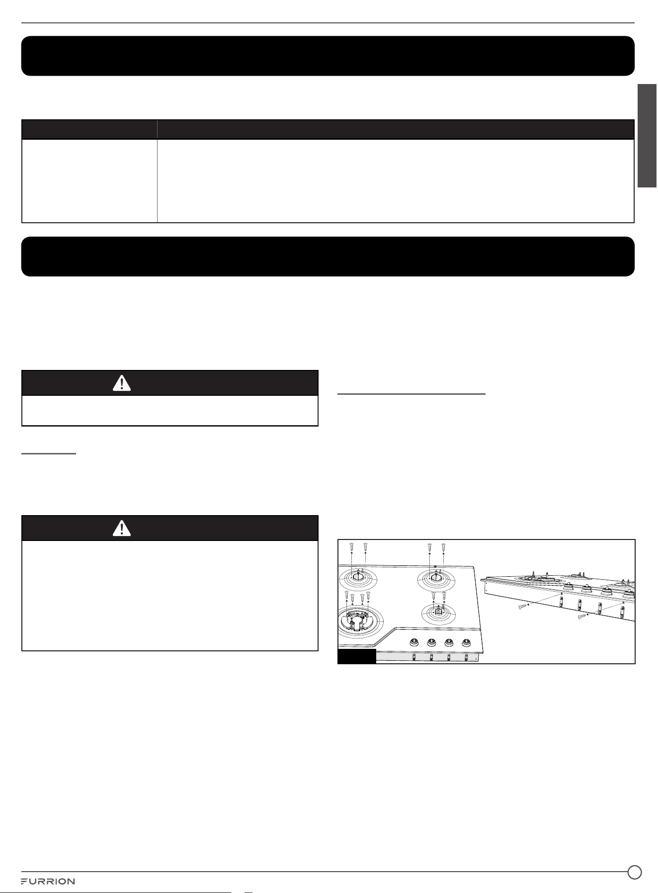
Replacing Components
To replace other gas and electrical components, that are
lodged inside the cooktop, it is enough to remove the work
top unscrewing the fixing screws of the burners
1. Removed the clamping brackets from bottom of the
cooktop by unscrewing the 4pcs screws M4 x 10mm.
2. Take out of the cooktop from the cabinet.
3. Removed the burner caps and burner bases
corresponding.
4. Remove the SS panel from the cabinet by unscrewing the
relative fixing screws. (Fig. 27)
Fig. 27
5. Replace the seal each time you change a tap in order to
guarantee a perfect tightness between body and rail.
CCD-0005859 Rev. 02.27.2023
14
English
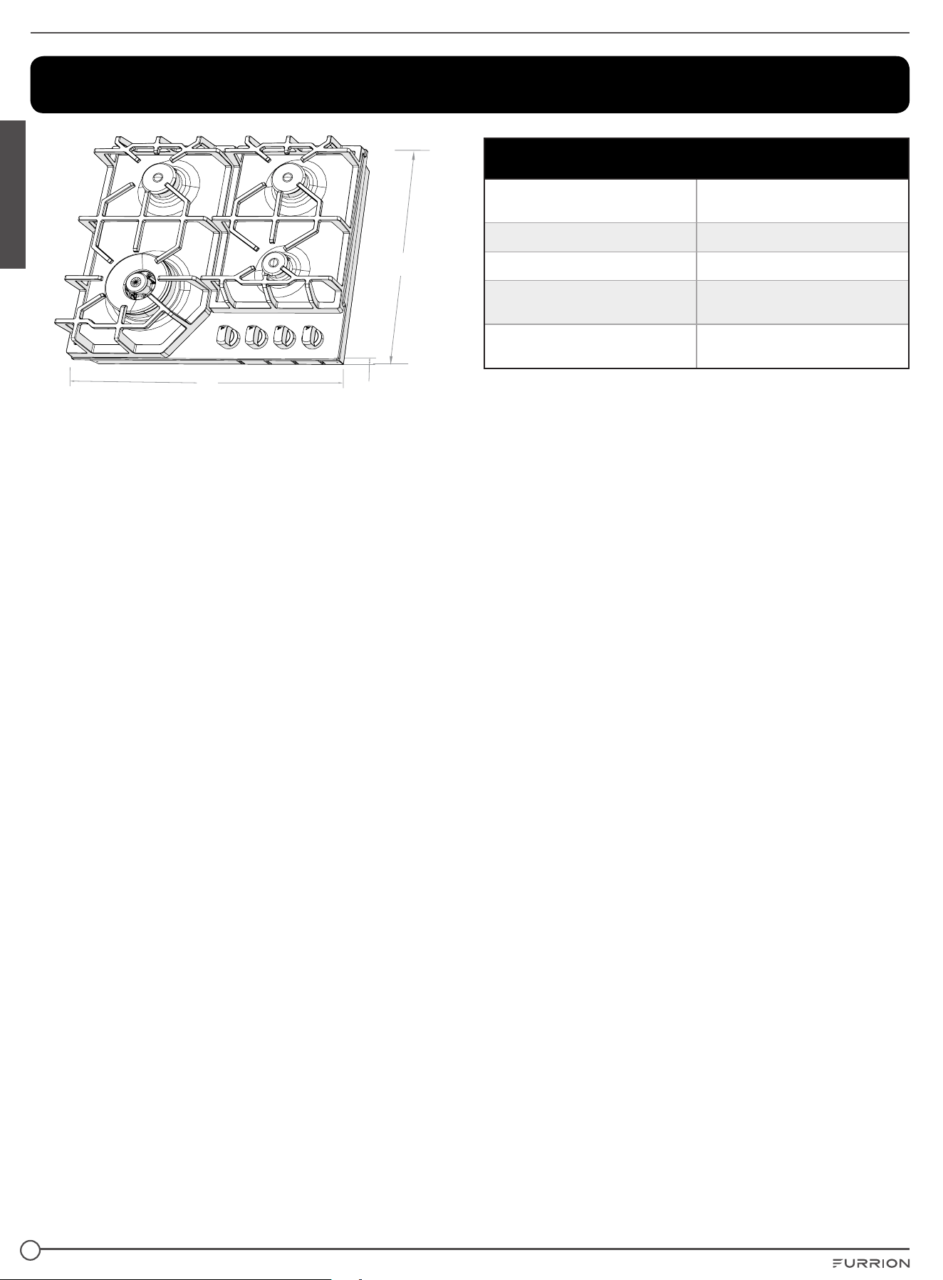
Specifications
D
W
H
Specification
Parameter (rating voltage,
frequency)
120VAC, 60Hz
Power Consumption
120V
Lighting Power Consumption
0.6W
Product Dimension (W x H x D)
22
13
/
16
” x 19
5
/
8
” x 4
1
/
16
”
(580 x 500 x 108mm)
Cut Out Dimension (W x H)
2111/16" x 2113/16"
(551 x 478mm)
CCD-0005859 Rev. 02.27.2023


IM-FHA00056 V1.0
Th
e contents of this manual are proprietary and copyright protected by Lippert. Lippert prohibits the copying or
dissemination of portions of this manual unless prior written consent for an authorized Lippert representation
has been provided. Any unauthorized use shall void any applicable warranty. The information contained in this
manual is subject to change without notice and at the sole discretion of Lippert. Revised editions are available
for free download from lippert.com.
Please recycle all obsolete materials.
For all concerns or questions, please contact Lippert
CCD-
0005859 Rev. 02.27.2023