
BULLETIN NO.
54-26-2770
SERVICE PARTS LIST
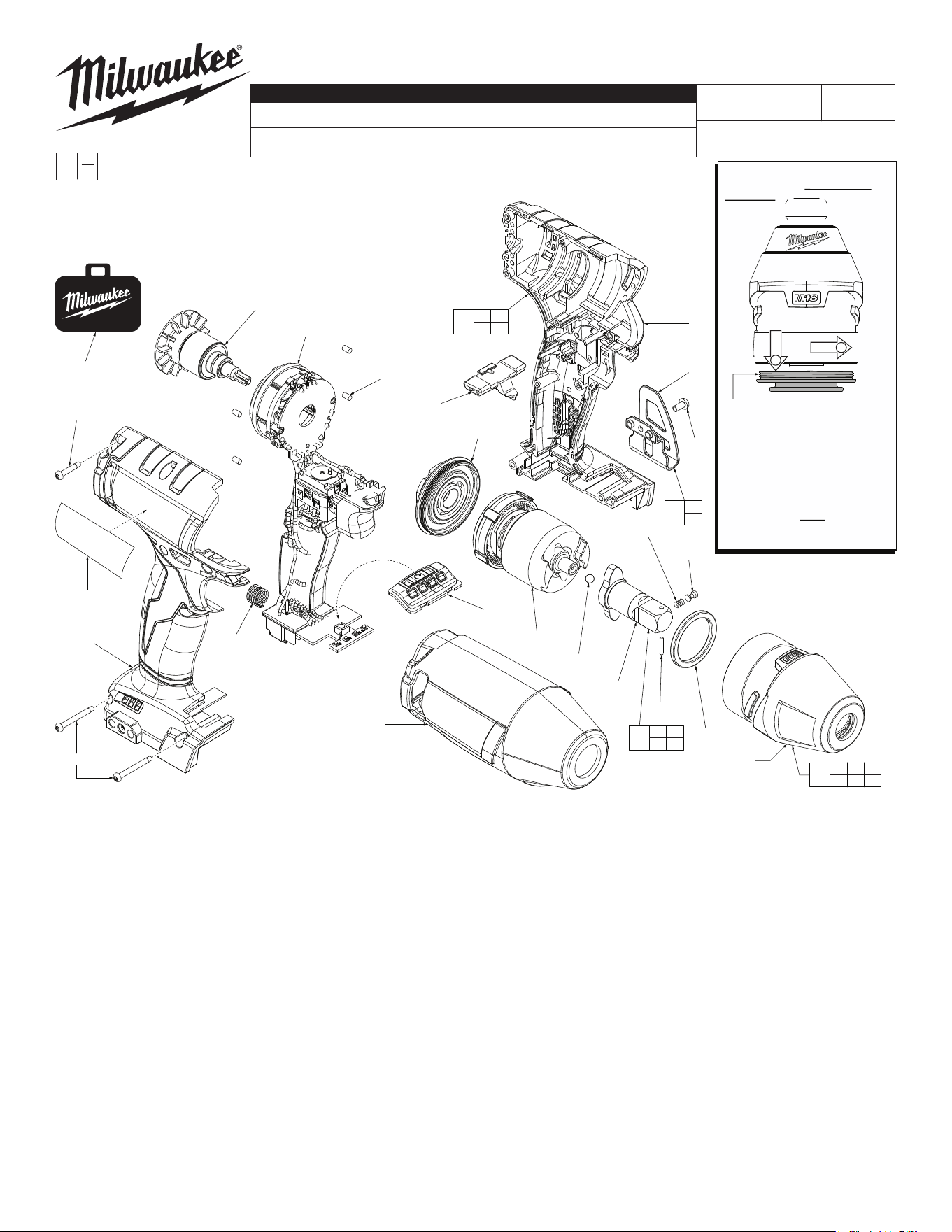
FIG. PART NO. DESCRIPTION OF PART NO. REQ.
4 45-88-2653 Plastic Washer (1)
8 02-02-1300 5.0mm Steel Ball (1)
23 45-30-2653 Rubber Slug (4)
30 06-82-0013 M3 x 38mm Pan Hd. ST TP T-10 Screw (2)
31 06-82-6350 M3 x 16mm Pan Hd. ST T-10 Screw (7)
32 12-20-0046 Service Nameplate (1)
33 --------------- Housing Halve - Right (1)
35 --------------- Housing Halve - Left (1)
36 --------------- Belt Clip (1)
37 06-82-0130 6-32 x 5/16" Pan Hd. T-15 Screw (1)
38 45-24-0013 Forward / Reverse Shuttle (1)
39 40-50-1090 Spring (1)
43 44-60-0014 Detent Pin (1)
44 44-60-0022 Pivot Pin (1)
45 40-50-0925 Detent Spring (1)
46 --------------- 1/2" Square Anvil (1)
50 42-55-2754 Blow Molded Carrying Case (1)
62 28-50-0012 Gearcase with Bushing (1)
64 44-66-0028 Gearcase End Cap with Ball Bearing (1)
65 14-46-0016 Impacting Assembly (1)
66 31-44-0033 Housing Assembly (1)
68 45-24-0044 Speed Selector Assembly (1)
70 16-07-2754 Rotor Assembly (1)
71 14-20-0016 Electronics Assembly (1)
73 14-30-0013 Gearcase / Anvil Assembly (1)
75 49-12-0012 Rubber Boot (Optional, Accessory) (1)
77 42-06-0018 1/2" Square Anvil Assembly (1)
79 42-70-0059 Belt Clip Assembly (1)
CATALOG NO. 2755-20
REVISED BULLETIN
SPECIFY CATALOG NO. AND SERIAL NO. WHEN ORDERING PARTS
M18™ FUEL™ 1/2" Square Impact Wrench (Baseline)
STARTING
SERIAL NO.
DATE
Feb. 2020
WIRING INSTRUCTION
G78A
SEE PAGE 2
FIG. LUBRICATION
(Type 'J' Grease, No. 49-08-4220):
62 Coat inside of bushing inside front gearcase (62) with grease.
65 Lightly coat the I.D. of the ring gear and the center of the
planet gears of impacting assembly (65) with grease.
70 Coat pinion of rotor assembly (70) with grease.
EXAMPLE:
Component Parts (Small #) Are Included
When Ordering The Assembly (Large #).
0
00
31(7x)
32
33
30(2x)
70
71
23(4x)
38
64
68
65
8
4
62
35
36
37
39
79
36
37
66
23 33
35
75
73
43 44 45
46
62 64
50
IMPORTANT NOTE: Gearcase
end cap #64 is LEFT HAND
THREAD!
Left Hand Thread
As an aid to assembly, carefully
lower the complete front end of
tool (gearcase/impacting system)
onto the gearcase end cap. Gen-
tly hand tighten front end assem-
bly onto gearcase end cap. Be
careful not to cross-thread! Once
installed by hand, seat gearcase
end cap with a good adjustable
wrench using light pressure.
Do not over tighten!
Model
2753-20
Shown
1
2
NOTE: Components of the Impacting
Assembly (65) can drop out of the
gearcase (62). Care must be taken to
hold these elements in place when
assembling onto gearcase end cap.
46
44
77
43 44
45 46
45
43
MILWAUKEE TOOL
l
www.milwaukeetool.com
13135 W. Lisbon Road, Brookeld, Wisc. 53005
Drwg. 3
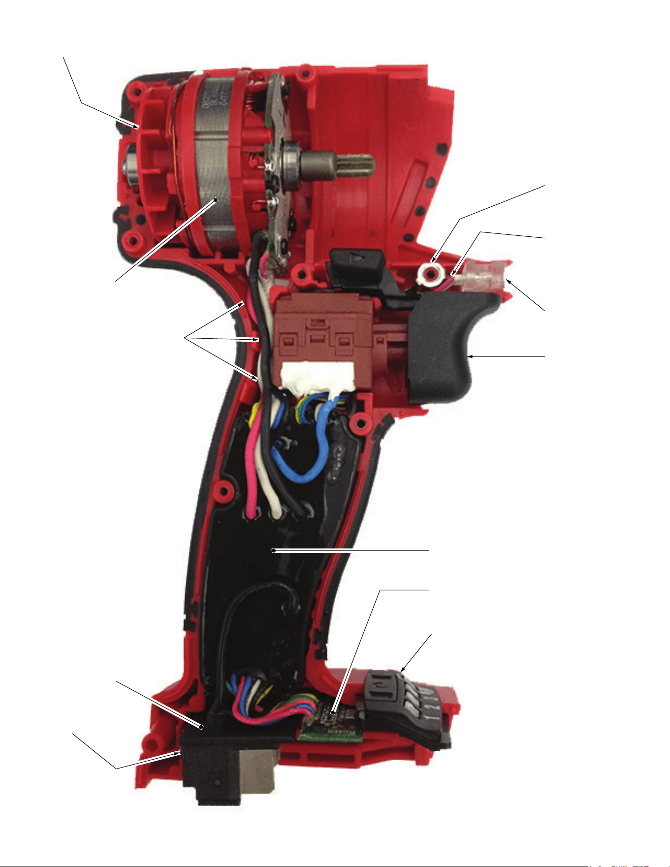
Rotor Assembly
Stator Assembly
with Hall PCBA
Watch for pinched wires here.
Tuck leads down in cavity
behind switch.
Battery Connector
Block Assembly
Compression
Spring
High Voltage
Protection Wire.
Place terminal
over screw boss
and route down
in cavity behind
forward/reverse
shuttle.
Route LED wires
down in cavity
behind forward/
reverse shuttle.
LED Assembly
On-Off Switch
Main PCBA
Speed PCBA
Speed Selector Assembly