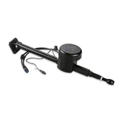

CLASS B COMPACT DRIVE UNIT
INSTALLATION INSTRUCTIONS
Important Safety Information
WARNING
See the Important Safety and Product Information guide in the autopilot product box for product warnings and
other important information.
You are responsible for the safe and prudent operation of your vessel. The autopilot is a tool that enhances your
capability to operate your boat. It does not relieve you of the responsibility of safely operating your boat. Avoid
navigational hazards and never leave the helm unattended.
To avoid possible personal injury and damage to your boat, the autopilot system should be installed by a
qualified marine installer. Specific knowledge of marine steering and electrical systems is required for proper
installation.
CAUTION
To avoid possible personal injury, always wear safety goggles, ear protection, and a dust mask when drilling,
cutting, or sanding.
When in use, beware of hot surfaces on the heat-sink, motor, and solenoid components to avoid possible
personal injury.
NOTICE
The drive unit movement must be limited by physical end stops. Failure to install end stops will cause the drive
unit to act as a travel limiter and will damage the drive unit.
When drilling or cutting, always check what is on the opposite side of the surface to avoid damaging the vessel.
To obtain the best performance and to avoid damage to your boat, install this drive unit according to these
instructions. Professional installation of the drive unit is highly recommended, because specific knowledge of
rudder operation is required to properly install the drive unit. Read all installation instructions before proceeding
with the installation. If you experience difficulty during the installation, contact Garmin
®
Product Support.
Contacting Garmin Support
• Go to support.garmin.com for help and information, such as product manuals, frequently asked questions,
videos, and customer support.
• In the USA, call 913-397-8200 or 1-800-800-1020.
• In the UK, call 0808 238 0000.
• In Europe, call +44 (0) 870 850 1241.
Tools Needed
• Tiller arm (if needed)
• End stops to limit rudder travel (if not already present on the boat)
• Safety glasses
• Drill and drill bits
• Wrenches
• Torque wrench
• LOCTITE
®
638
™
retaining compound or equivalent (recommended)
• Hex or allen wrenches (for removing the device from the base for maintenance or repair)
GUID-0954FD14-8C5B-48E8-AF7D-CB1B24776C3B v4February 2024

Mounting Location Considerations
NOTICE
This device should be mounted in a location that is not exposed to extreme temperatures or conditions. The
temperature range for this device is listed in the product specifications. Extended exposure to temperatures
exceeding the specified temperature range, in storage or operating conditions, may cause device failure.
Extreme-temperature-induced damage and related consequences are not covered by the warranty.
The drive unit must be installed within specific extension and angle limitations, as mentioned below and defined
in the specifications at the end of these instructions. Exceeding the extension or angle limitations will damage
the drive unit. Installation-related damage is not covered by the warranty.
The position feedback sensor on the drive unit may be affected by magnetic interference. Installing the drive
unit in close proximity to a magnetic device may result in poor product performance.
When selecting a mounting location, observe these considerations.
• The drive unit must be installed under deck, in a location not subject to flooding or washdown.
• The drive unit must be mounted securely on a surface that is able to withstand the high thrusts generated by
the rudder.
• The drive unit movement must be limited by physical stops, and not by the length of the drive unit rod, or
damage to the drive unit will occur.
• No part of the drive unit or rod should contact the vessel, quadrant, or tiller arm throughout the full range of
movement.
• You must not exceed the 10 degree tilt at the extremes of the stroke, because it will damage the drive unit.
• The drive unit must not be installed in a location that is near strong magnetic interference, such as near the
back of a speaker or subwoofer.
◦ Safe mounting distance from a typical marine speaker is at least 20cm (8in.).
◦ Safe mounting distance from other devices can be estimated by multiplying their specified compass-safe
distance measurement by 0.05.
Tiller Arm and End Stop Considerations
You can connect the drive unit to either an existing quadrant or to a tiller arm (not included). If you do not have
a quadrant or cannot install the drive unit at your quadrant location, choose a tiller arm that fits the diameter of
your rudder post and is the correct length for the installation location.
The supplied tiller bolt is suitable for a quadrant or tiller arm thickness of 12mm (0.47in.) to 16mm (0.63in.).
The drive unit must not act as a rudder-movement limiter. Physical end stops (not included) must be in place to
limit the drive-unit travel to 254mm (10in.) from fully retracted to fully extended, or damage to the drive unit will
occur.
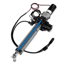
Mounting the Drive Unit
Hardware is supplied to fasten the drive unit to the mounting surface. The supplied M8 bolts, washers, and nuts
are suitable for mounting the cylinder on a surface between 12mm (0.47in.) and 24mm (0.95in.) thick.
1 With the drive unit in the mounting location, mark the locations of the four mounting holes on the surface.
2 Verify the marked locations.
The marked locations should be 76.2mm (3in.) apart .
3 Drill 8.8mm (0.35in.) holes through the mounting surface.
4 Secure the drive unit to the mounting surface using the supplied M8 bolts, washers, and nuts.
5 Tighten the bolts to 17Nm (12.5ft-lbf).
2
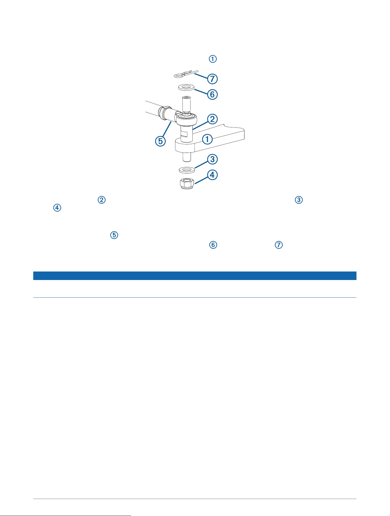
Installing the Tiller Pin
The supplied tiller bolt is suitable for a quadrant or tiller arm thickness of 12to 16mm (0.47 to 0.63in.).
1 Drill a 12.2mm (0.48in.) hole in the quadrant or tiller arm (not included) for the tiller bolt.
2 Place the tiller bolt into the quadrant or tiller arm, and secure it with the M12 washer and the M12 lock
nut .
It is recommended to apply LOCTITE 638, or an equivalent retaining compound, to the tiller bolt where it
passes through the quadrant or tiller arm.
3 Place the drive unit rod on the tiller bolt.
4 Fasten the rod to the tiller bolt with the other M12 washer and the locking pin .
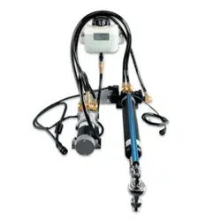
Connecting the Drive Unit to a Garmin Autopilot
NOTICE
The cables connected to the drive unit should not be cut, because cutting the drive-unit cables voids your
warranty.
Consult the installation instructions provided with your Garmin autopilot to install the autopilot components
and to connect the drive unit to the correct component.
3
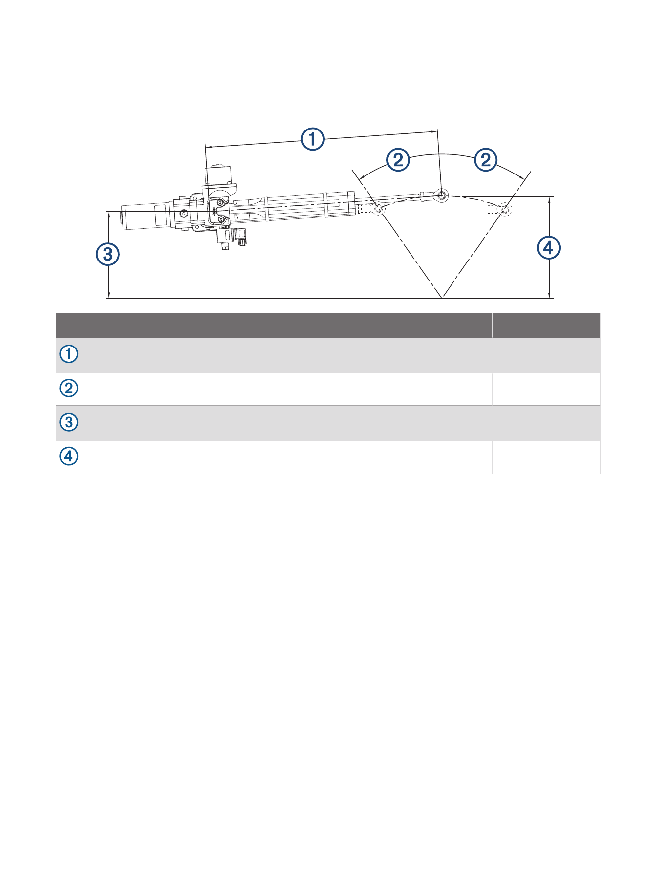
Drive Unit Installation Example
This example shows a typical cylinder installation on a 213mm (8.39in.) quadrant or tiller arm with a total
rudder angle of 70 degrees (2 × 35 degrees).
Item Description Measurement
Distance from the center of the drive unit base to the tiller bolt when the rudder is
amidships.
574.8mm (22.63in.)
Degree of travel from amidships to the installed physical stops. 35 degrees
Distance from the center of the drive unit base to the relative location of the
rudder post.
174.7mm (6.88in.)
Distance from the center of the tiller bolt to the rudder post. 213mm (8.39in.)
Maintenance
To maximize the life of your drive unit, these maintenance guidelines should be observed.
• The cylinder rod should be kept free from damage.
• The drive unit should not be exposed to salt water.
• The mounting hardware and the tiller-bolt hardware should be inspected on a regular basis, and any
components should be tightened if necessary.
• The rod end and the tiller bolt should be kept lubricated with marine-grade grease. Only high-quality marine
grease that is compatible with nitrile seals should be used.
4
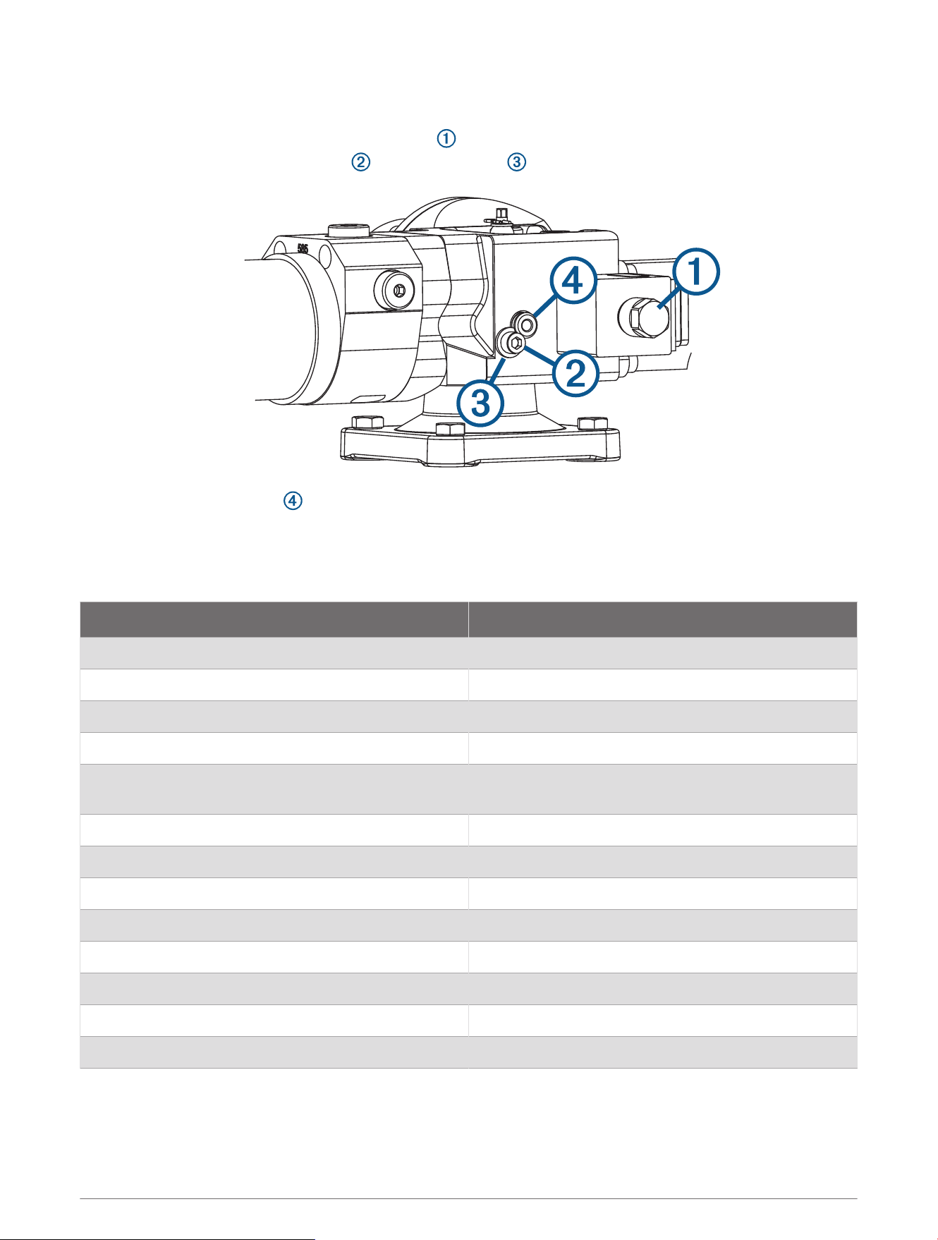
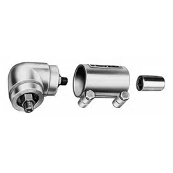
Removing the Drive Unit from the Base
The drive unit can be removed from the base for service, if needed.
1 Remove the motor coil, secured by a 17mm nut .
2 Loosen and remove the allen screw and retaining plate .
3 Remove the mounting pin to release the drive unit from the base.
If the pin is difficult to remove, you can remove the plastic cap from the head of the pin and insert the screw
you removed in step 2 to provide a grip for pliers.
Specifications
Specification Value
Input voltage 12Vdc (regulated by the autopilot)
Current rating at 100% duty (continuous) 12.5A
Current rating at 50% duty 17.5A
Current rating at 25% duty 22.5A
Current rating with intermittent duty (peak current at
max. load)
25A
Max. operating thrust 6900N (1,551lbf) (intermittent)
Clutch coil 12W
Weight 9kg (19.84lbs)
Water-ingress protection IP67
EMC protection BS EN 60945:2002 (DC)
Ignition protection BS EN 8864:1990
Operating temperature (normal) 5° to 35°C (41° to 95°F)
Operating temperature (limits) -15° to 50°C (5° to 122°F)
5
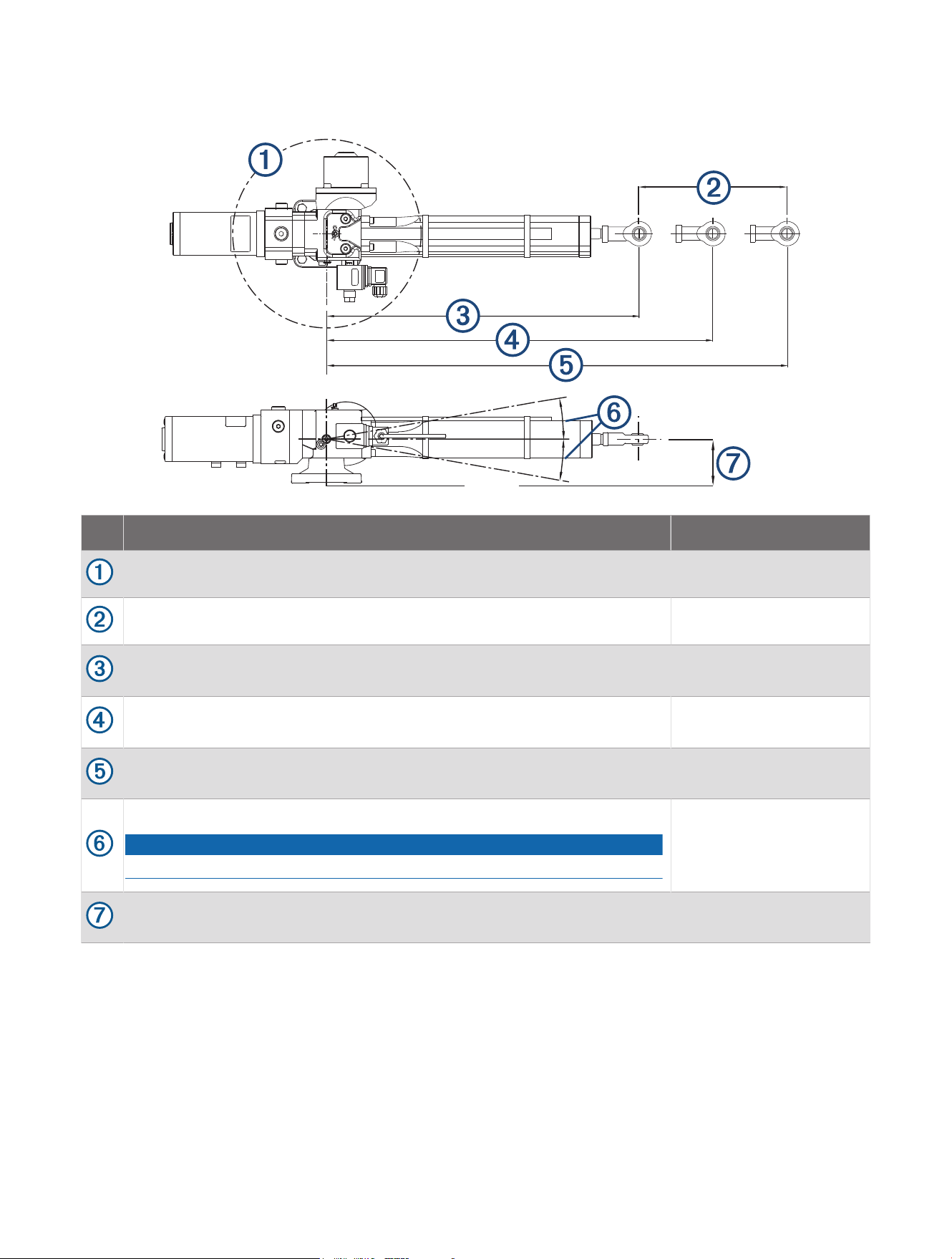
Drive Unit Dimensions
Item Description Measurement
Pivot radius. 360 degrees
Stroke distance from fully retracted to fully extended. 254mm (10in.)
Distance from the center of the mount to the tiller bolt when the rod is fully
retracted.
446.5mm (17.58in.)
Distance from the center of the mount to the tiller bolt when the rudder is
amidships.
574.8mm (22.63in.)
Distance from the center of the mount to the tiller bolt when the rod is fully
extended.
700.5mm (27.58in.)
Maximum tilt angle of the drive unit when it is at the extremes of the stroke.
NOTICE
Exceeding this angle will damage the drive unit.
10 degrees above or
below center
Distance from the center of the drive unit rod to the base of the drive unit
when at rest.
64mm (2.52in.)
© 2023 Garmin Ltd. or its subsidiaries
Garmin
®
and the Garmin logo are trademarks of Garmin Ltd. or its subsidiaries, registered in the USA and other countries. These trademarks may not be used without the
express permission of Garmin.
LOCTITE
®
638
™
is a trademark of Henkel Corporation in the U.S. and elsewhere.
© 2023 Garmin Ltd. or its subsidiaries
support.garmin.com