
B500
User Manual V1.0
Please Read This Manual Before Use And Follow Its Guidance.
Keep This Manual For Future Reference.
Thank You!
Thank you for making BLUETTI a part of your family.
From the very beginning, BLUETTI has tried to stay true to a sustainable future
through green energy storage solutions for both indoor and outdoor use while
delivering an exceptional eco-friendly experience for our homes and our world.
That's why BLUETTI makes its presence in 100+ countries and is trusted by
millions of customers across the globe.

Instruction
Copyright © 2023 ShenzhenPowerOakNewenerCo., Ltd. All rights reserved.
No part of this document may be reproduced or transmitted in any form or by any
means without the prior written consent of ShenzhenPowerOakNewenerCo.,
Ltd.
Notice
BLUETTI's products, services, and features are subject to the agreed-upon terms
and conditions during purchase. Please note that some products, services, or
features described in this manual may not be available under your purchase
contract. Unless otherwise specified in the contract, BLUETTI makes no repre-
sentations or warranties of any kind, express or implied, with respect to the
contents of this manual.
The contents of this manual are subject to change without notice. Please get
the latest version from BLUETTI official website.
If you have any questions or concerns about this manual, please contact
BLUETTI customer service.
ShenzhenPowerOakNewenerCo., Ltd.
19F, Block A, Kaidaer Building,No. 168 Tongsha Road, Nanshan District,
Shenzhen, Guangdong,China

About the Manual
Purpose
This user manual describes the installation, electrical connection, commission-
ing, maintenance and troubleshooting of B500 battery system. Please read and
understand all instructions in this manual before use.
Target Audience
• Installation, operation, and maintenance technicians
Symbol Conventions
This manual uses the following symbols to highlight important information:
Danger
Warning
Caution
Attention
Instruction
It indicates a hazardous situation which, if not avoided, will
result in death or serious injury.
It indicates a hazardous situation which, if not avoided, could
result in death or serious injury.
It indicates a hazardous situation which, if not avoided, could
result in minor or moderate injury.
It indicates a potentially hazardous situation which, if not
avoided, could cause substantial damage to property and the
environment.
It contains important additional information as well as useful
tips for the safe, efficient, and hassle-free operation of the
EP760 Hybrid Inverter

Safety Guideline
B500 Battery
Features
Battery Overview
Battery Interface
LED Indicators
Battery Cables
System Installation
Installation Procedure
Installation Preparation
Installation Requirements
Stacking the B500 battery
Electrical Connection
System Check
Monitoring and setting
Download the App
Binding
Connection
Real-time Monitoring
System Disposal
Specifications
FAQs (Frequently Asked Questions)
Contents
1
2
2.1
2.2
2.3
2.4
2.5
3
3.1
3.2
3.3
3.4
3.5
4
5
5.1
5.2
5.3
5.4
6
7
8
06
18
18
18
19
20
21
22
22
22
27
29
31
37
39
39
39
40
42
43
44
45

JUST POWER ON06
1. Safety Guideline
1.1 Safety Instructions
1.1.1. Disclaimer
Read this manual for instructions on the proper use and safety information for the unit.
Pay attentionto the "Instruction", "Caution", "Warning" and "Danger" symbols in this
manual, and follow theinstructions carefully to avoid injury or damage.
The Safety Requirements provided herein are for illustrative purposes that include but are
not limited to those listed in this manual. Actual operation shall comply with all applicable
safety standards. If you have any questions, feel free to contact BLUETTI support or your
local BLUETTI dealers.
To ensure a safe and reliable operation, it’s crucial to carefully observe and adhere to the
following conditions :
• Always operate or store the equipment in the conditions specified in this manual.
• The installation and ambient conditions must comply with the regulations in the
relevant international, national or regional standards.
• Avoid unauthorized disassembly, equipment replacement, or modification of
software codes.
BLUETTI shall not be liable for damages resulting from the following circumstances:
• Force majeure events such as earthquakes, fires, storms, floods, or mudslides.
• Damages caused by improper handling and installation that do not meet the
requirements outlined in the manual.
• Damages resulting from inadequate storage conditions as specified in the manual.
• Hardware or data damage caused by customer negligence, improper operation, or
intentional actions.
• System damage caused by third parties or customers.
• Adjustments, changes, or removal of labels in violation of this manual.
• Usage of the product in devices with high-performance UPS requirements,
including but not limited to data servers, workstations, medical equipment, and
others.

JUST POWER ON 07
1.1.2 General Safety
•
Do not install, use and maintain the unit in adverse weather conditions such as
lightning, rain, snow, and strong breezes (including but not limited to handling
and operating the unit, plugging and unplugging signal connections to outdoor
facilities, working at height, outdoor installations, etc.).
• Always turn off the power source before starting any electrical work.
• Do not clean the equipment with water.
• Do not disassemble, modify, tamper with, or repair the equipment on your own.
• Regularly inspect the unit and its accessories for damage.
• Use a tester to check for the presence of dangerous voltage before touching any
conductor or terminal.
• If the equipment’s shell is cracked during transportation or use, do not use it and
contact BLUETTI support or your local BLUETTI dealers.
• Use a dry powder fire extinguisher if the equipment catches fire.
• In case of fire, EVACUATE the building or affected area immediately, activate the
closest FIRE ALARM system and CALL your local emergency phone number.
• Use genuine cables and accessories provided by BLUETTI.
• Keep the unit away from heat sources or high temperatures, and do not expose it
to direct sunlight.
• Do not store the equipment with flammable liquids, gases, or explosive materials.
• Make sure the place where you are using the equipmentis well-ventilated and
spacious.
• Do not block or cover the openings of the equipment, as this may cause irrevers-
ible damage to it.
• Use the equipment for its intended purpose and avoid stacking objects on top of it
during storage or use.
• Do not move the unit during operation as the vibrations and shocks associated
with movement may cause damage to the internal hardware.
Danger
Follow these guidelines for proper operation.

Instruction
JUST POWER ON08
1.2. Installation Safety
Danger
Avoid working with live electrical components.
Before installation, double check the equipment for any signs of
damage or defects to minimize potential risks.
Make sure that the equipment and all associated switches are in the
"OFF" position to prevent electric shock.
Do not touch any terminal while the equipment is running, as it may
pose a risk of electric shock.
1.1.3 Personnel Requirements
•
The installation, commissioning, and maintenance should only be performed by
trained professionals who follow proper safety precautions and operating practices.
• To operate BLUETTI equipment, professionals must possess the necessary qualifica-
tions and certifications required by local regulatory authorities for tasks like
high-voltage operations, working at heights, and specialized equipment operations.
The transportation, wiring and maintenance shall comply with all
applicable laws, regulations and standards.
User-provided materials and tools required shall meet the require-
ments specified in applicable laws, regulations and relevant
standards.
• Turn off the equipment IMMEDIATELY in case of malfunction, and contact the
BLUETTI support team if this manual cannot explain the malfunction adequately
to you.
• Do not place the equipment on unstable or inclined surfaces.
Keep away from children and pets.
Comply with applicable laws and regulations.
•
•
•
•
•
•

JUST POWER ON 09
Warning
The installation should only be performed by qualified professionals
or trained personnel.
All cables should be securely connected and meet appropriate
specifications.
Do not touch the equipment, as the shell may become hot when it’s
running.
Attention
Handle the equipment and accessories with care during loading,
unloading and transportation.
1.2.1 General Requirements
•
Before starting any work, turn off and isolate all electricity to the property at the
main panel.
• Take measures to prevent the electricity from turning back on while working, such
as a safety tag and lockout.
• Test the circuit's voltage before proceeding to verify that the course is off.
• After installing the equipment, remove the idle package materials from the site
such as cartons, foam, plastic, nylon ties, etc.
• Keep people other than the installation technicians away from the B500 battery.
• When handling equipment and accessories, pack them in their original packaging
or other materials to protect them from impact.
• Seal all the wiring ports with fireproof and water-proof materials to prevent
possible electric shock or other risks.
• It’s prohibited to alter, damage or cover the marking and nameplate of any part of
B500 battery.
• Check and make sure all safe guards, including screws and waterproof rings, are in
place and properly tightened.
• Keep the B500 battery firmly secured to the ground or other solid objects, such as
a wall or mounting bracket.
• Use a non-abrasive cloth to clean the equipment and accessories. Do not use water
or harsh chemicals.
• Please follow the instructions to install the B500 battery.
•
•
•

JUST POWER ON10
1.3 Battery Safety
1.3.1 Statement
BLUETTI shall not be liable for equipment abnormality component damage,
personal injury property loss or other damage caused by the following reasons:
• Failure to promptly charge the battery after installation and system connection, leading
to over-discharge and subsequent damage.
• Repeated over-discharging of batteries due to improper maintenance or capacity
expansion (e.g., mixing new and used batteries) or prolonged periods without full
charging.
• Neglecting to follow the battery maintenance guidelines outlined in the user manual.
• Failure to charge the battery as required during storage, resulting in capacity loss or
irreparable damage.
• Improper operation or connection errors causing battery short-circuits, damage, drops, or
leaks.
• Usage of the battery in ways not specified in the user manual, including combining it
with other batteries, regardless of brand or rated capacity.
1.2.2 Anti-static Requirements
•
Wear or use personal protective equipment (PPE) or clothing that is appropriate for
the work; this may include items such as safety glasses or goggles, or a face shield
(with safety glasses or goggles), hearing protection, dust mask, gloves, anti-static
bracelet, safety boots or shoes, or rubber boots.
• If you use an anti-static bracelet for electrical connections, make sure the bracelet
is properly grounded.
1.2.3 Drilling Requirements
When drilling holes in the wall or on the ground, the following safety measures
should be considered.
• Wear goggles and protective gloves at all times.
• Shield and protect the equipment to prevent debris from falling into it and remove
all debris after drilling.
• Drill holes on the unit are forbidden, as this may damage the equipment's electro-
magnetic shielding performance. The metal shavings may cause short circuits on
the circuit board.

JUST POWER ON 11
1.3.2 General Requirements
•
Do not expose the battery to high temperatures or around heat sources, such as
sunlight, fire, transformers and heaters. If the battery overheats, it may cause a fire.
• To avoid leakage, overheating or fire, do not disassemble, modify or damage the
battery. For example, do not insert foreign objects into the battery or place the
battery in water or other liquids.
• If any part of the battery is immersed in water, do not touch the battery to avoid
electric shock. Please contact the battery recycling company for handling.
• Do not short-circuit the battery terminals. A short circuit can cause a fire.
• Never use damaged batteries or components. Improper use or misuse of
damaged batteries or components can damage your device or injure yourself as a
result of battery fluid leakage, fire, overheating, or explosion.
• Do not perform welding or grinding work around the battery to prevent fire
caused by sparks or arcs.
• Do not store damaged batteries near undamaged ones, as damaged batteries
may leak flammable liquid or gas. Only qualified professional or trained personnel
is allowed to approach damaged batteries.
• The fire hazard of lithium-ion battery Hybrid Inverter is high. Before handling
batteries, consider the following risks:
(a)Battery thermal runaway may produce flammable and harmful gases such as
CO and HF. Vapors from burning batteries may irritate eyes, skin and throat.
(b)The concentration of flammable gases from battery thermal runaway may lead
to deflagration and explosion.
(c)The battery electrolyte is flammable, toxic and volatile.
• Avoid contact with spilled liquid or gas if the battery leaks chemicals or odors. Do
not approach the battery and contact a professional for disposal. Professionals
must wear goggles, rubber gloves, gas masks and protective clothing.
• Electrolyte is corrosive and can cause irritation and chemical burns. If you come
into direct contact with battery electrolyte, do the following:
(a)Inhalation of Vapors: Evacuate contaminated area, get fresh air immediately,
and seek medical attention.
(b)Eye Contact: Immediately flush eyes with water for at least 15 minutes, do not
rub eyes, and seek medical attention immediately.
• Battery damage due to non-compliance with the battery operating environment or
external power supply parameters.

JUST POWER ON12
Danger
Use carbon dioxide, FM-200, or ABC dry powder fire extinguisher.
Remind firefighters to avoid contact with high-voltage components
to prevent the risk of electric shock.
Overheating may cause the battery to deform and leak corrosive
electrolytes or toxic gas. Keep away from batteries to avoid skin
irritation and chemical burns.
(c)Skin Contact: Immediately wash the infected area with soap and water and seek
medical attention immediately.
(d)Ingestion: Seek medical attention immediately.
• Use the battery within the temperature range specified in this manual.
• Do not expose the battery to humidity or corrosives, as this may cause the battery
to rust, corrode and leak chemicals.
• Do not turn the battery upside down or tilt it.
• Do not ignore warning signs on parts or products made by the manufacturer.
1.3.3 Installation Requirements
•
Do not use batteries with compromised packaging.
• Make sure the battery switch is in the OFF position.
• Tighten the screws securely and conduct regular checks.
• Prevent the positive and negative terminals of the battery from touching each
other or any metal objects to avoid heat generation or electrolyte leakage.
• After installing the equipment, remove unused packing materials such as foam,
carton, plastic and excess cables from the equipment area.
Fire Emergency Measures
•
•
•
JUST POWER ON 13
1.3.4 Battery Disposal
•
Safely and carefully disposeofused batteries by the provisions of local laws and
regulations. Avoid treating batteries as regular household waste, as improper
disposal can lead to environmental pollution.
• If you find a leaking or damaged battery pack, contact us immediately or an
authorized battery recycling partner for expert assistance.
• If the battery pack reaches the end of its lifespan, please contact the battery
recycling company for further assistance.
• To maintain battery integrity, do not expose used batteries to high temperatures or
direct sunlight.
• Protect used batteries from moisture and corrosive substances to avoid potential
hazards.
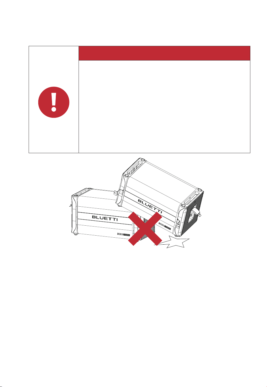
Danger
If the battery pack is dropped, violently impacted or tilted during
installation, internal damage may occur. So do not use such battery
packs to avoid safety risks such as battery leakage and electric shock.
If the dropped battery is not obviously deformed or damaged, and
there is no abnormal smell, smoke or fire, please contact a profes-
sional to transfer the battery to an open and safe place, and contact
BLUETTI support.
If the battery is obviously damaged or there is an abnormal smell,
smoke or fire, please evacuate immediately, and contact a profes-
sional or BLUETTI support. Professionals can use fire extinguishing
facilities to extinguish the fire under safety protection.
Battery Drop Emergency Measures
Fig. 1-1
•
•
•

Danger
The equipment generates high voltage during operation, which can
cause electric shock leading to severe injury, property damage, or
even death. Please strictly follow the safety instructions provided in
the user manual and adhere to relevant electrical safety codes.
JUST POWER ON14
1.4 Electrical Safety
1.4.1 General Requirements
•
Make sure that all electrical connections comply with your local electrical standards.
• User-prepared cables should adhere to local laws and regulations.
• When performing high-voltage operations, use insulated tools for safety.
• Wear anti-static gloves during work and avoid clothing that generates static electricity.
1.4.2 Grounding Requirements
•
Always make the ground connection first and disconnect it last when installing or
removing the equipment.
• Take care not to damage the grounding conductor.
• Before operating the equipment, always confirm that it is securely and reliably grounded.
1.4.3 Wiring Requirements
•
Keep cables at least 30mm away from the heating devices or heat sources to prevent
damage caused by excessive heat.
• Group cables of the same type together to minimize electromagnetic interference.
Additionally, ensure that cables of different types should be laid at least 30mm apart
without intertwining and crossing.
• Cables used in the PV grid-connected power generation system must be firmly connect-
ed, well insulated, and has proper specifications.
• Take necessary measures to protect cables when passing through pipes or holes.
• Safe Construction Practices:
(a) All cable installations should be carried out in environments above 0℃ to maintain
cable flexibility and integrity. Handle the cable with care, especially when working in low
temperature environments.
(b) If the cable has been stored below 0℃, allow it to acclimate to room temperature for a
minimum of 24 hours before installation.
1.5 Maintenance Requirements

JUST POWER ON 15
To ensure your safety while maintaining the B500 battery, please follow the following steps:
Step1: Disconnect the power grid.
Step2: Disconnect the battery and solar systems.
Step3: Wait at least 30 minutes until the equipment is discharged.
• Follow the anti-static requirements to prevent electric shock and other potential
hazards.
• For any maintenance needs, please contact your local authorized service center.
• Place temporary warning signs or erect fences to prevent unauthorized access to
the maintenance site.
• To ensure personal safety and proper equipment usage, establish a reliable
grounding connection before use.
• Wear personal protective equipment (PPE) during operation. If there is a possibility
of personal injury or equipment damage, stop operation immediately, and take
appropriate protective measures.
• Use tools correctly to avoid injury or damage to equipment.
• Do not touch energized equipment.
• Do not clean the electrical components inside and outside the cabinet with water.
• Do not stand, lean on or sit on top of the equipment.
• Do not damage the equipment modules.
• When the battery fails, avoid touching the battery and be careful of high temperature.
• Do not disassemble or damage the battery. The released electrolyte is harmful to
your skin and eyes. Avoid contact with electrolyte.
• Batteries can cause electric shock and high short-circuit current. When using
batteries, please note the following:
(a)Remove any metal objects, such as watches and rings, from yourself.
(b)Use tools with insulated handles.
(c)Wear rubber gloves and boots.
(d)Avoid the metal objects to short circuit battery terminals.
(e)Do not place tools or metal parts on top of the battery.
(f)Disconnect the charging power source before connecting or disconnecting
battery terminals.

JUST POWER ON16
1.6 Transportation Requirements
All components of the B500 battery leave the factory in optimum electrical and mechani-
cal state. It's necessary to use original or appropriate packaging to ensure the product
safety during transportation. When you receive the product, inspect for any kind of
damage and note the damage on the delivery receipt. The shipping company will be
responsible for any damage or loss of the product during transportation. If necessary,
please contact us for further assistance.
1.7 Storage Requirements
•
When not using the B500 battery for extended periods of time, power it off and
remove all electrical connections.
• Charge the B500 battery to 40%-60% SoC before storage.
• In order to keep the battery healthy, fully charge and discharge the B500 battery every
6 months.
• Make sure the place where to store the B500 battery is well ventilated and spacious.
• Do not store the B500 with flammable liquids, gases, or explosive materials.
Maintenance checklist(Performed once every six months)
Inspection items Inspection methods
Switch gear and
battery module
Wire and cable layout
Grounding
Function inspection
Check the following items. In case of nonconformity, take corrective
actions immediately:
• Check whether there are flammable objects around the battery
module.
• Check whether the battery module is reliably fixed on the wall,
and whether any fixing point is corroded.
• Check the switch gear and battery module for damage, paint
peeling, oxidation, etc.
The inspection must not be carried out until all internal devices of
the battery module are powered off! In case of nonconformity
found in inspection, take corrective actions immediately:
• Check the cable layout for short circuit and compliance with the
specifications. If case of any abnormality, take corrective actions
immediately.
• Check the battery module for internal seepage of water.
• Check whether the cables are loose, and tighten them according
to the aforesaid torque.
Check whether the current, voltage and temperature in the BLUETTI
app of the battery system are within the operating ranges.
Check whether the grounding is correct.
JUST POWER ON 17
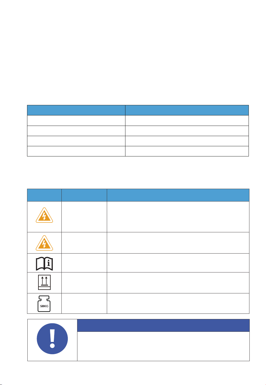
1.9 Label Description
Attention
The symbols on the box contain important information for safe operation.
The nameplate on the side of the box contains important parameter
information related to the product.
Table 1-2 Labels and Description
Label Name Description
Electrical shock
warning
The B500 battery generates high voltage during operation.
The installation, commissioning, and maintenance should
only be performed by qualified professionals or trained
personnel.
Warning Be careful. Hazards may occur during operation.
Read instruction
Please read the instruction carefully before operating
the B500 battery.
This side up
It must be transported, handled and stored in the
correct orientation. The arrow always faces upwards.
Weight
The battery packs are quite heavy and need to be
carried by several people.
This Side Up
1.8 Handling Requirements
Table 1-1 Recommended Number of People Based on the Weight of Product
Weight
<18kg
18kg~32kg
32kg~55kg
>55kg
Number of people
1
2
3
4 or a cart
•
•
• You’re strongly recommended to clean the surface frequently with a dry soft cloth.
• Keep away from children and pets.
• Do not stack anything on top of the equipment either in storage or in use.
• Avoid exposing the equipment to rain, humidity or direct sunlight.
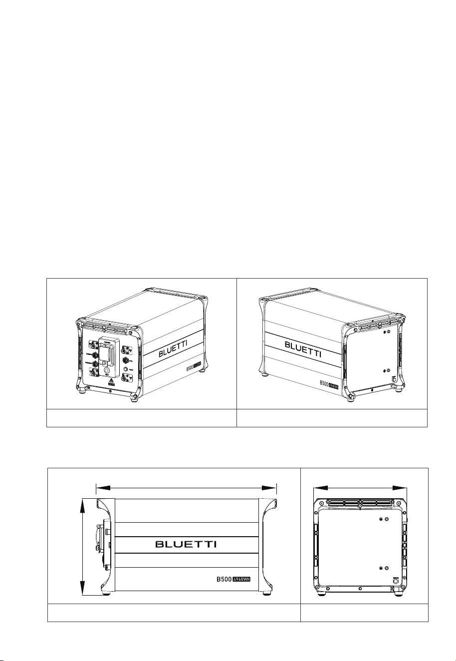
324mm
338mm
626mm
Left Right
2. B500 Battery
2.1 Features
The B500 battery is designed for residential and light commercial use. Single B500
battery pack has a capacity of 4.96kWh.
The B500 comes with a reliable battery management system (BMS) with a
multi-stage architecture that provides real-time detection of the battery pack's
voltage, current and temperature, protecting the system from overvoltage, under-
voltage, overcurrent, overtemperature and undertemperature. At the same time,
the redundancy design provides unprecedented safety and stability for the B500
battery.
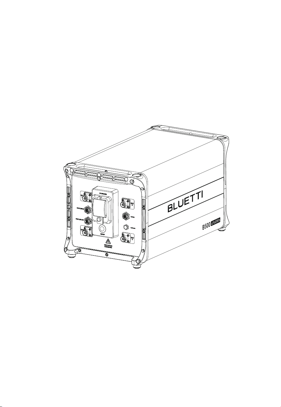
2.2 Battery Overview
2.2.1 B500 Appearance
Table 2-1
2 .2.2 Dimensions
Table 2-2 (Unit: mm)
Front Right
JUST POWER ON18
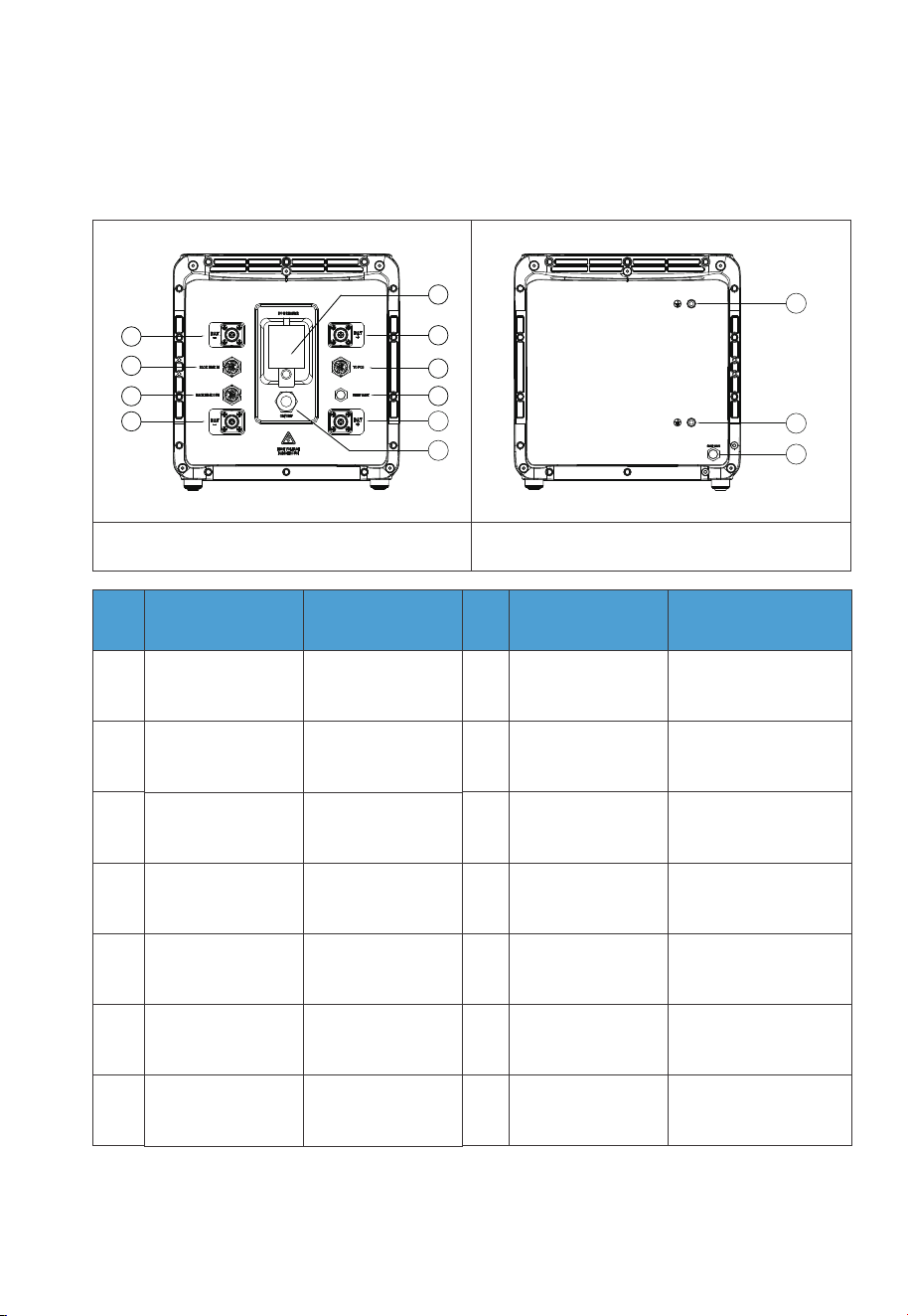
2.3 Battery Interface
2.3.1. B500 Interface
Table 2-2
Left
No.
1
2
3
4
5
6
7
8
9
10
11
12
13
BAT- terminal 1
Pack link-in
Pack link-out
BAT- terminal 2
Main switch
BAT+ terminal 1
Bleed valve 1
BAT+ terminal 2
Power button
Grounding port 1
Grounding port 2
Bleed valve 2
Inverter signal port
(TO Pcs)
No.Name
DVC-C
DVC-A
DVC-A
DVC-C
Not applicable
DVC-C
DVC-A
Decisive Voltage
Classification
Not applicable
DVC-C
Not applicable
Not applicable
Not applicable
Not applicable
Decisive Voltage
Classification
Name
Right
1
2
3
4
5
6
7
8
9
10
11
12
13
JUST POWER ON
19

2.3.2. Interface Description
Interface
⑦ Inverter signal
port(PCS LINK)
For communication between inverter and battery packs. Connect to the
LINK PORT 2 of EP760 inverter via the battery communication cable.
Connect to the BAT+ terminal of another B500 or EP760 inverter.
Connect to the BAT- terminal of another B500 or EP760 inverter.
For communication between battery packs. Connect to the battery
pack signal output port of the upper battery via the communication
cable when multiple B500s are stacked.
For communication between battery packs. Connect to the battery
pack signal input port of the lower battery via the communication
cable when multiple B500s are stacked.
②Battery pack
signal input port
(PACK LINK IN)
③Battery pack
signal output port
(PACK LINK OUT)
⑨BAT+ terminal
④BAT- terminal
Description
Table 2-4
2.4 LED Indicators
Light
OFF B500 is not started. Can operate the circuit breaker.
Can not operate the circuit breaker.
Can not operate the circuit breaker.
B500 is running.
B500 is shutting down.
B500 is not running.
ON
Flash at 0.5Hz
Flash at 1Hz
Description Note
If all indicators are flashing, the battery
module is temporarily unavailable and is
restoring, please wait patiently.
If it lasts for more than 1 hour, please
contact an authorized dealer or our
company.
If a single indicator flashes, the B500 is in
a fault condition. Please contact an
authorized dealer or our company.
Table 2-5
JUST POWER ON20

2.5 Battery Cables
Picture Description Interface (connect to)
Communication Cable
Red battery expansion cable (Positive)
Black battery expansion cable (Negative)
Grounding Cable
BAT+ terminal 2
BAT- terminal 2
Grounding port
Table 2-6 Battery Cables
LINK PORT 2 of
the inverter
JUST POWER ON
21
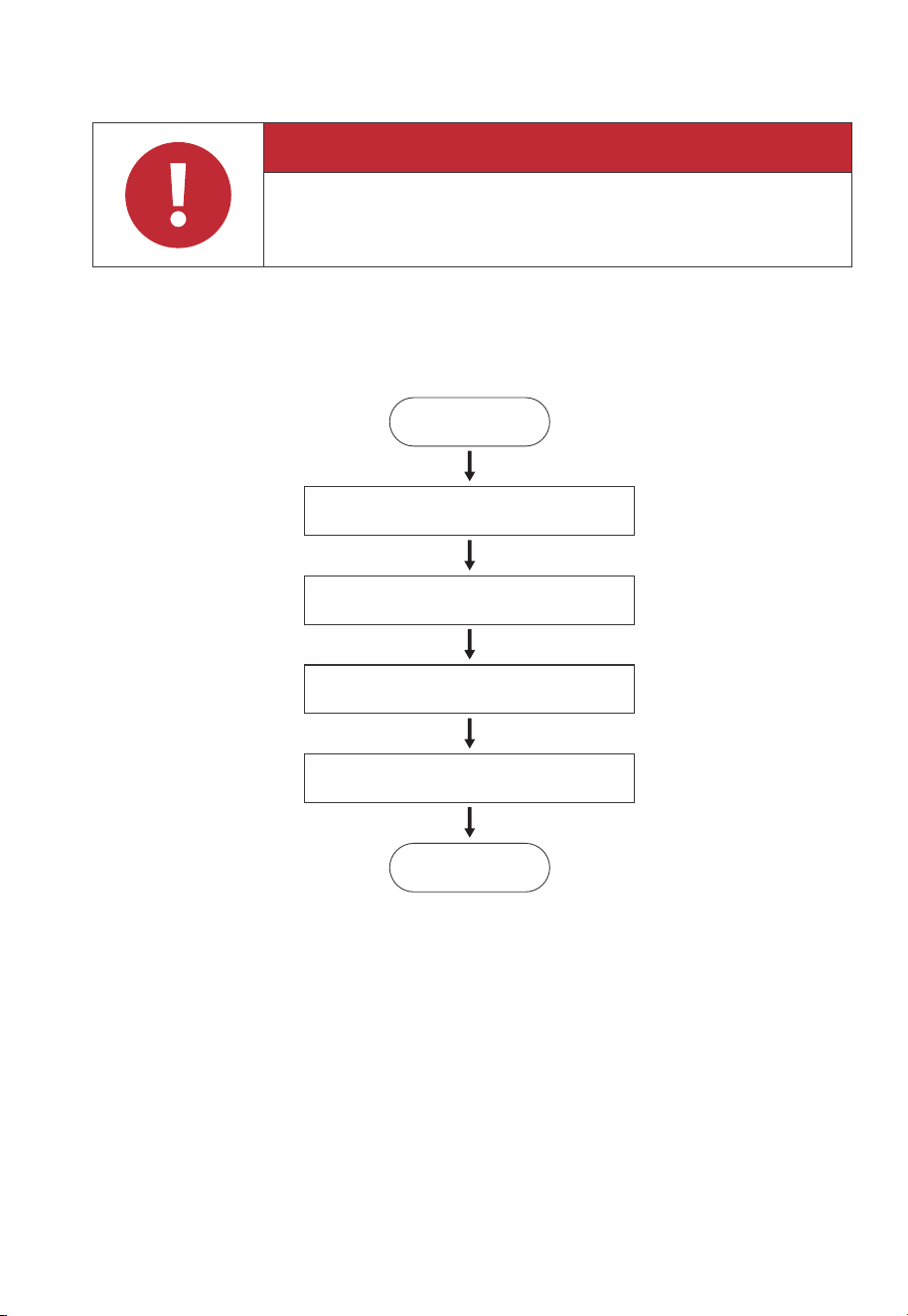
3. System Installation
3.1 Installation Procedure
Danger
Before installation, disconnect all circuit breakers for the battery pack,
solar system, and the main switch of the grid to ensure safe operations.
Start
Preparation
Stacking the batteries
Electrical Connection
System Check
End
3.2. Installation Preparation
3.2.1. Packing Lists
Upon receiving the package, we kindly ask you to carefully inspect and verify the presence
of all components and accessories included.
JUST POWER ON22
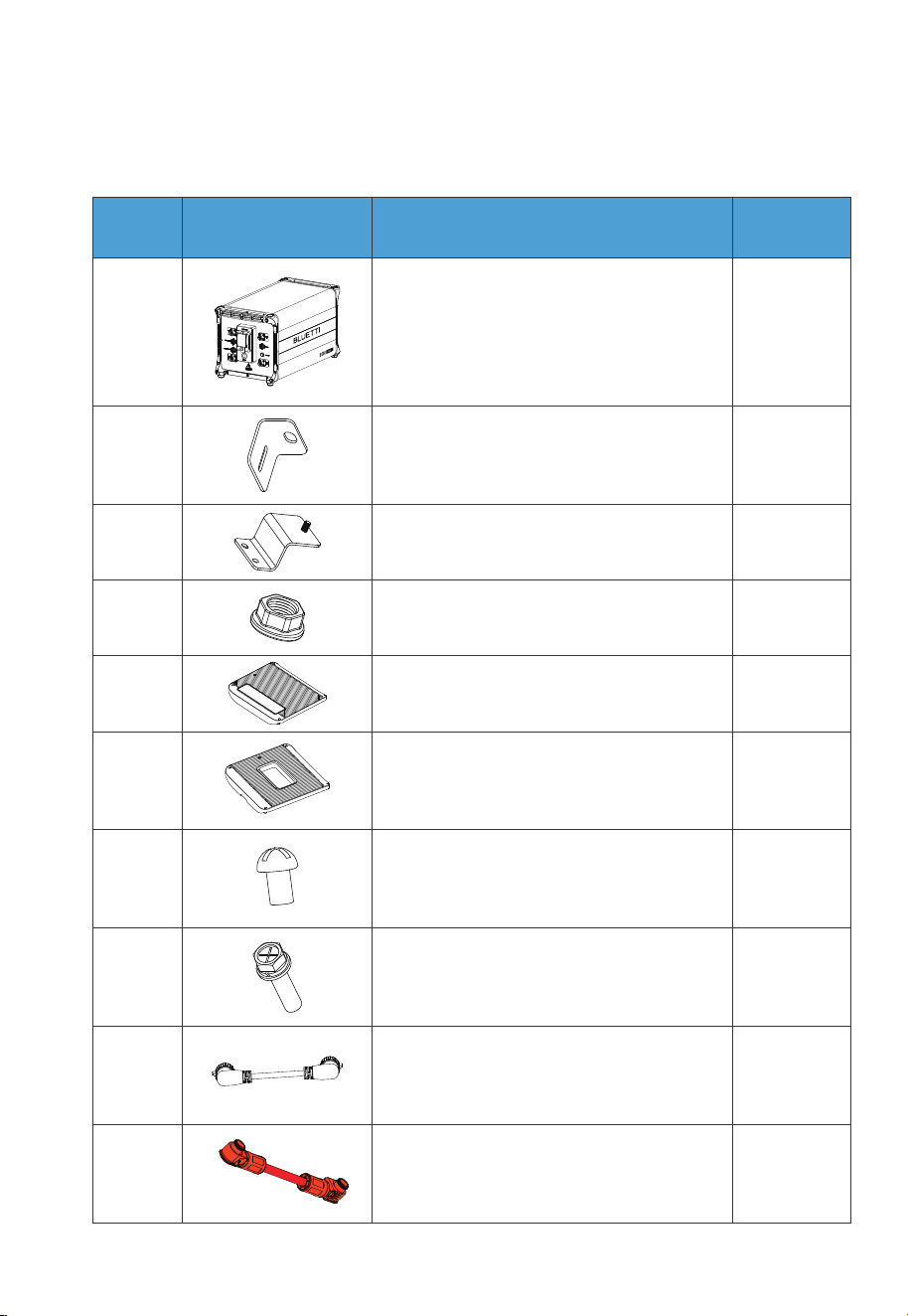
B500 Battery Packing List
1
2 2
2
23
B500 Battery Module
Bracket #1
Bracket #2
No. DescriptionPicture Qty.
24 M5 hex nut
15
Left cover
1
10
4
6
7
8
Right cover
M4*8 screw (for fastening covers)
M5*10 screw (for brackets)
1
1
9
10
Communication cable
Red battery expansion cable (Positive)
Table 3-1
JUST POWER ON
23
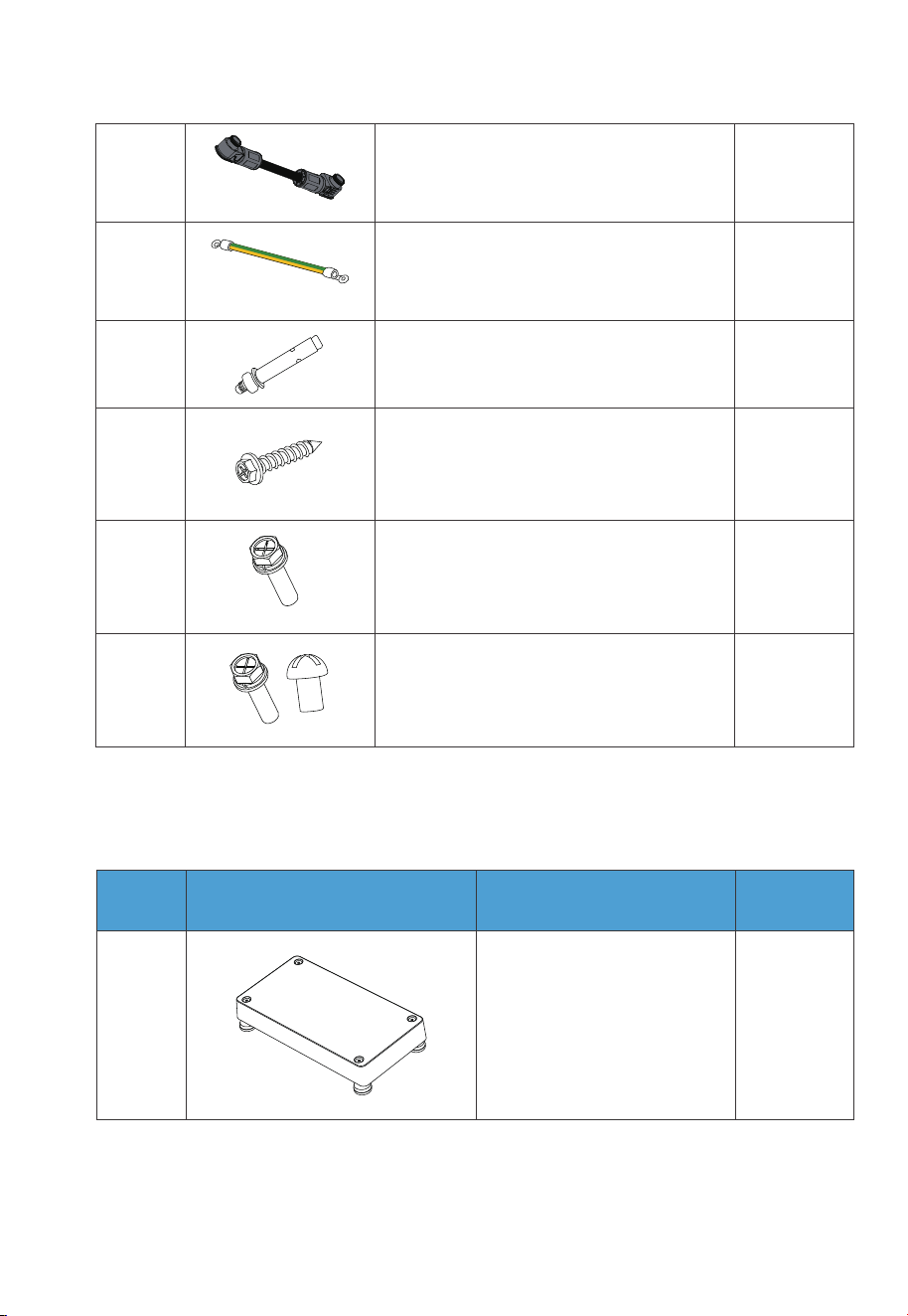
12
11
1Grounding cable
1Black battery expansion cable (Negative)
2
2
13
14
M8*60 expansion bolt (for brackets)
Self-tapping screw, ST8×40
2
1
15
16
M6*12 screw (Grounding cable)
Spare screw kit
3.2.2 Base Packing List
1
1
Base
No. DescriptionPicture Quantity
Table 3-2 Base Packing List
JUST POWER ON24
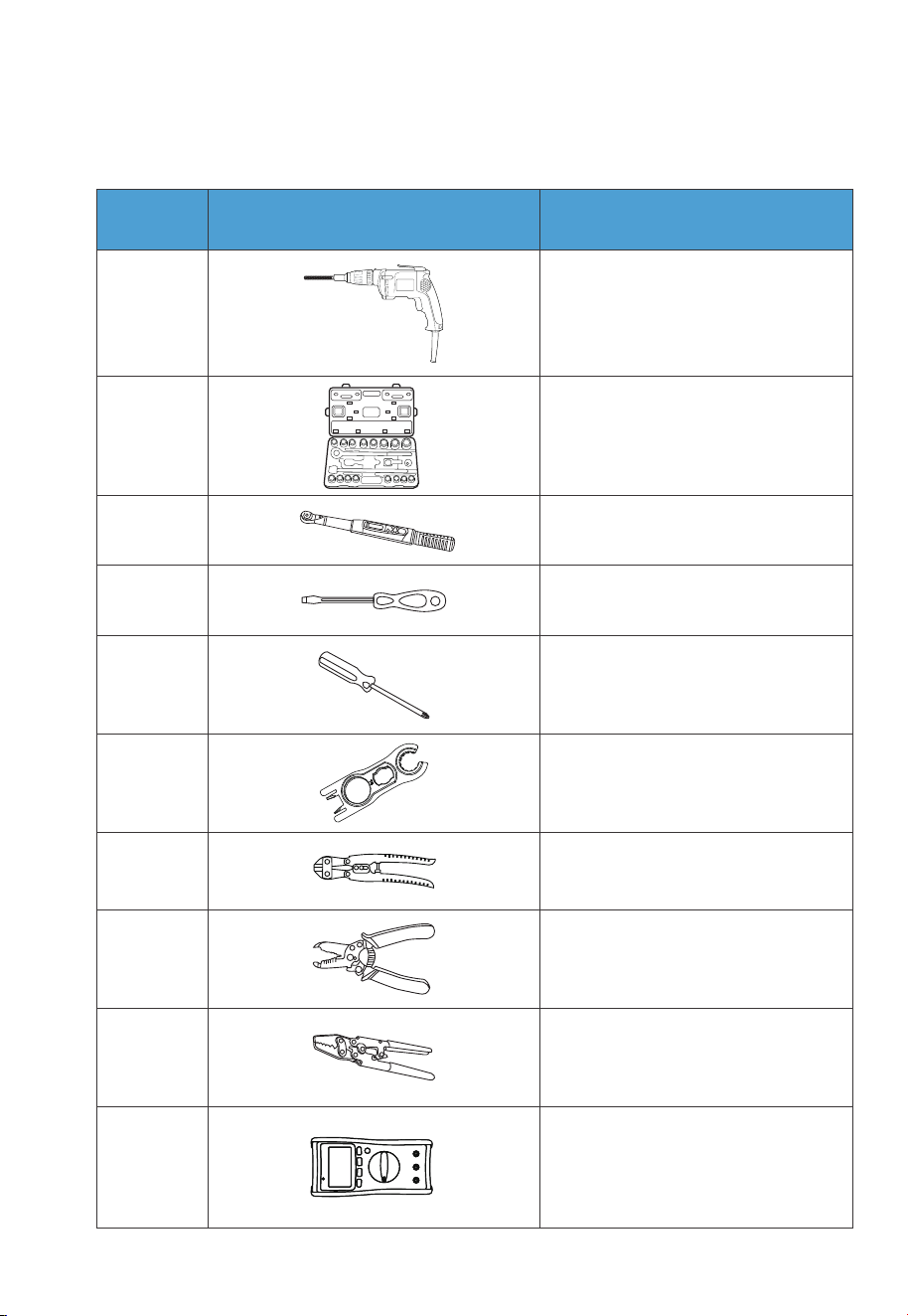
3.2.3 Required Tools
1
2
3
4
5
6
7
8
9
10
Electric drill
(5/8/10mm)
Socket wrench set
Torque wrench
Flat screwdriver
Cross screwdriver
(4mm)
MC4 spanner
Cable cutter
Cable stripper
Cable Crimper
Multimeter
(DC voltage ≥
1000VDC)
No. DescriptionPicture
Table 3-4 Required Tools
JUST POWER ON
25
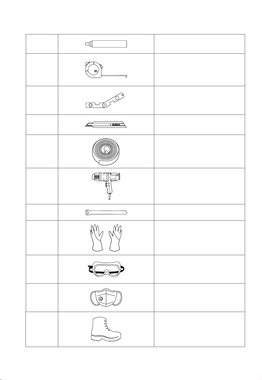
12
11
13
14
15
16
17
18
19
20
21
Measuring tape
Marker
Level ruler
Box cutter
Heat shrink tubing
Heat gun
Cable tie
Anti-static gloves
Protective goggle
Mask
Safety-toe shoes
JUST POWER ON26

22
Vacuum cleaner
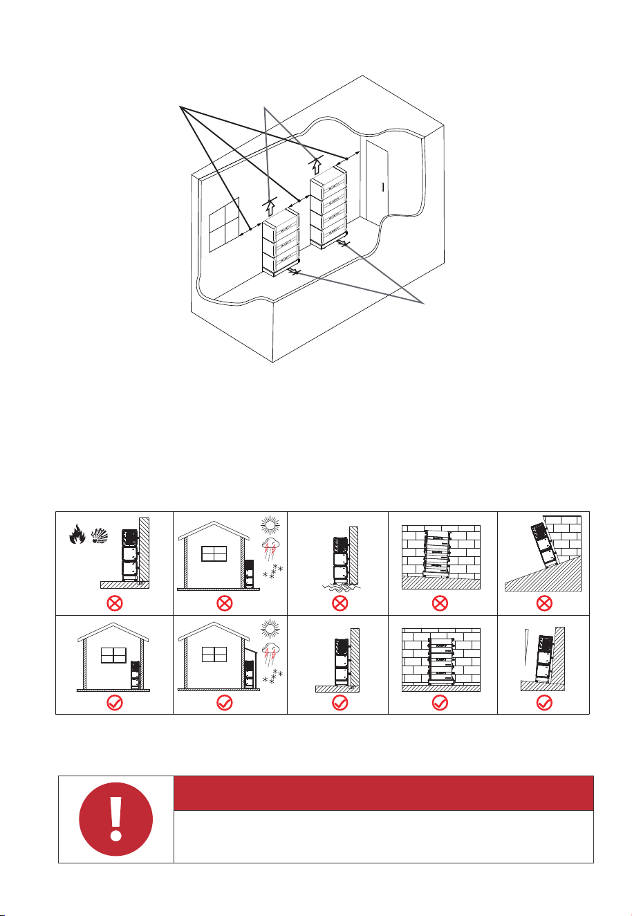
3.3 Installation Requirements
3.3.1 Environment Requirements
•
Install the B500 battery in a well-ventilated and spacious area to ensure good heat
dissipation.
• The B500 battery has an IP65 rating and can be installed indoors and outdoors.
Please note that if you place the system outside the house, use a cabinet to protect
it from direct sunlight, as this may cause a degradation in system performance.
• The enclosure and heat sink are very hot while the inverter is working, therefore do
NOT install the inverter in places where you might touch inadvertently.
• Keep the B500 battery away from flammable liquids, gases, or explosive materials.
• Keep away from children and pets.
• Do not install the B500 battery outdoors in salt-affected areas, as the accumulation
of salt may corrode the system. Salt-affected areas are those within 500 meters
from the coast or susceptible to sea breezes. Salt accumulation is influenced by
seawater, sea breeze, precipitation, air humidity, topography and forest cover of
adjacent sea areas.
• Do not install the system in low-lying areas where water tends to accumulate.
Otherwise, water may leak into the equipment and result in system failure.
• Ambient temperature range: -20℃~50℃
• Relative humidity: 5%~95% (non-condensing)
• Maximum height: 2000m.
Attention
Danger
If the battery pack is dropped, violently impacted or tilted during
installation, internal damage may occur. So do not use such battery
packs to avoid safety risks such as battery leakage and electric shock.
JUST POWER ON 27
3.3.2 Location Requirements
•
The B500 battery should be installed ona firm, flat, level base.
• Do not install the system on flammable materials.
• Consider the weight and placement of components to ensure adequate structural
support.
Figure 3-2 Installation Angle
Water
Fire or
Flammable
Material
Max. 5
o
3.3.3 Space Requirement
Danger
Make sure to check for any cables or pipes before drilling into the wall.
1m/40in
1m/40in
Door
Window
30.5cm/1 feet
JUST POWER ON28
Figure 3-1 Space Requirement
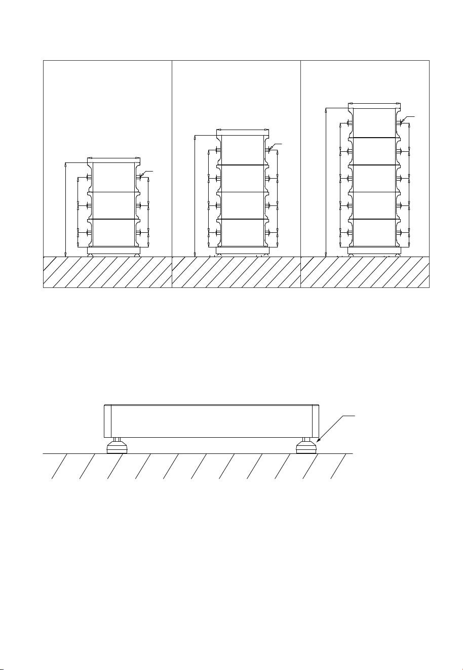
3.4 Stacking the B500 battery
Step 1: Place the base on the ground and adjust the height of leveling feet so that
the base stands stably on the ground. Don’t forget to tighten the nuts to secure the
leveling feet.
Step 2: Mark the drilling positions with tape and marker. Drill holes with an electric
drill and insert M8 expansion bolts.
Note: If you are working with a wooden wall, simply mark the positions and use M8
self-tapping screws to secure the unit directly onto the wall.
Step 3: Move the B500 battery pack to the base. Two people are required to transport
the B500. Align the bumps on the battery with the notches on the base to secure
the battery in place.
Figure 3-3 (Unit: mm)
Ground
The height of 4
leveling feet can
be adjusted.
Figure 3-4
( 3 layers) ( 4 layers) ( 5 layers)
171.5mm
325mm 340mm
1133mm
1458mm
1782mm
340mm325mm
171.5mm
Ø8
Ø8
Ø8
628mm
171mm 325mm 325mm 340mm
171.5mm 325mm 325mm 340mm
628mm
171.5mm
325mm 325mm
171.5mm
325mm 325mm
325mm 340mm
325mm
340mm
628mm
JUST POWER ON 29
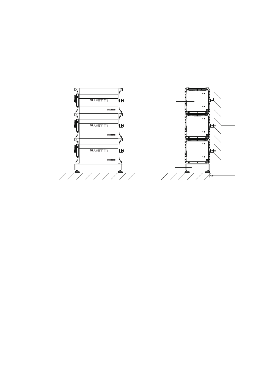
Step 4: Fix 2 brackets #1 to two sides of B500 with 4 M5*10 screws. Put the bracket #2
through the compression rivet screw of bracket #1 and M8 expansion bolts. Secure
the connection with M8 and M5 nuts.
Step 5: Repeat Step3 and 4 to secure all battery packs.
Figure 3-5
Ground
Wall
B500
Base
B500
B500
50-55mm
JUST POWER ON30
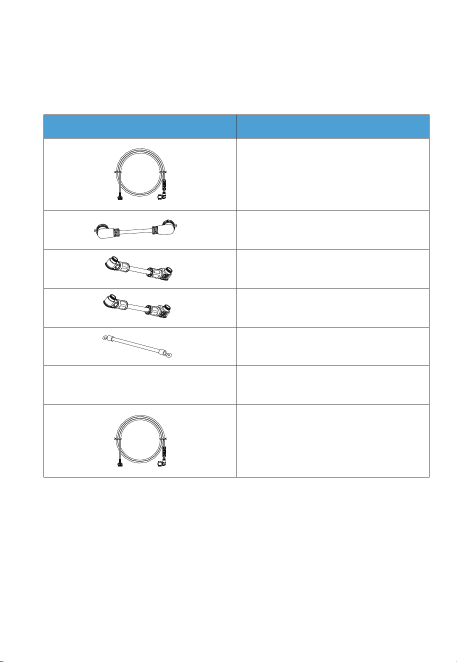
Table 3-5 Cables
CablePicture
3.5 Electrical Connection
3.5.1 Cables
Communication cable
Red battery expansion cable (Positive)
Black battery expansion cable (Negative)
Grounding cable
Outdoor multi-core copper cable
CT communication cable
COM communication cable
/
JUST POWER ON 31
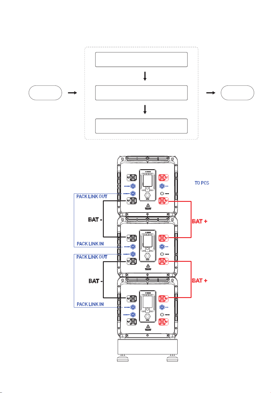
3.5.2 Connection Procedure
Start EndConnect Battery Power Cables
Connect Communication Cables
Connect Grounding Cables
BMS
JUST POWER ON32
1
2
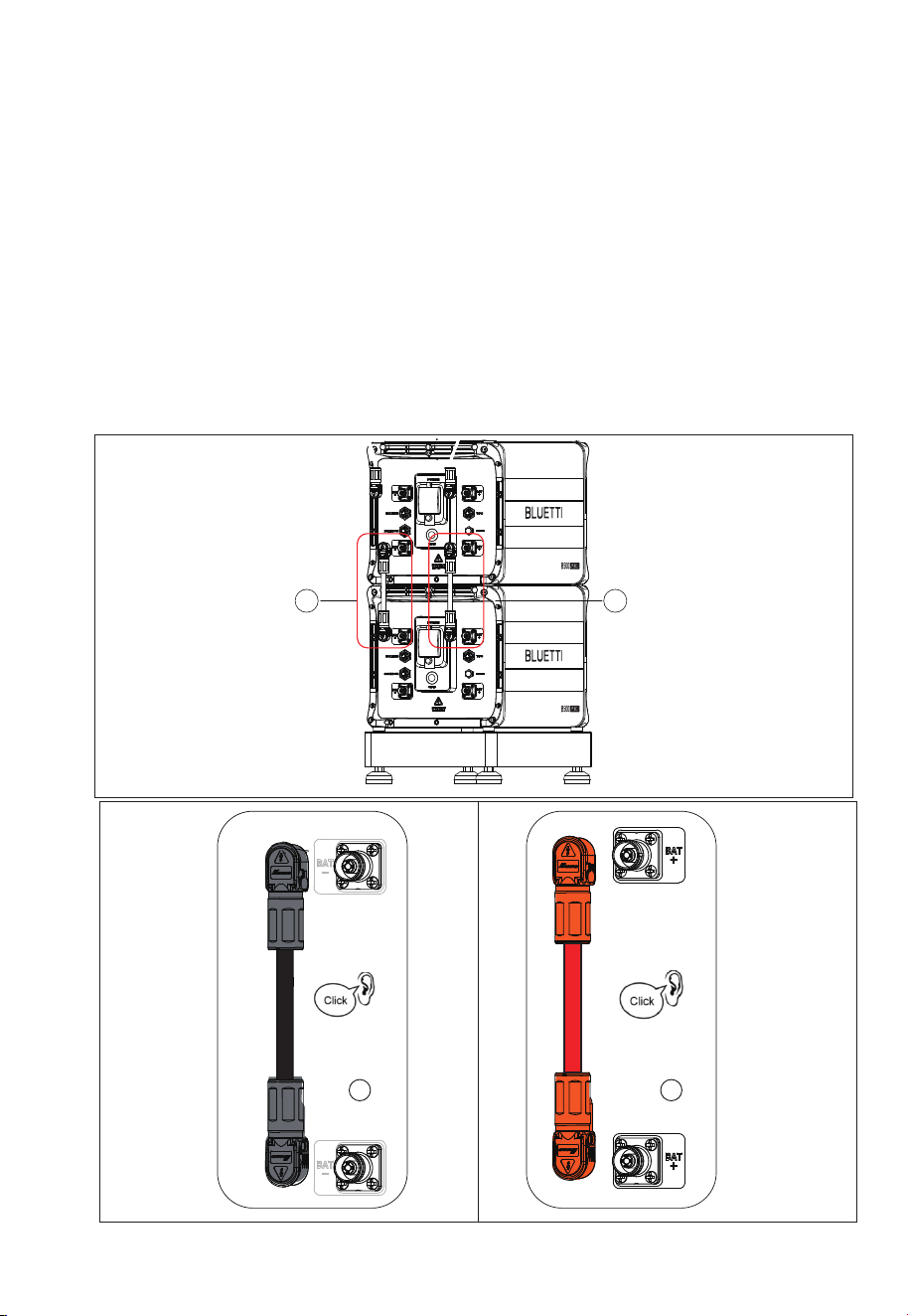
3.5.3 Connect Battery Power Cables
Step 1:Connect two B500 battery packs via the battery expansion cables - black
cable for negative terminals, red for positive terminals. See “①” “②” of Figure 5-9-1
and 5-9-2.
• Secure the black protection cover with M4 screws. See Figure 5-9-3.
• Connect the other end of the cable to the B500 BAT- terminal.
• Repeat to connect the red battery power cable. See Figure 5-9-4.
Recommended torque: Less than 6Nm for M8 screws, 1.2Nm for M4 screws.
Step 2:Check that the cables are properly connected.
Figure 5-9-1
1
2
Figure 5-9-2
Figure 5-9-2
JUST POWER ON 33
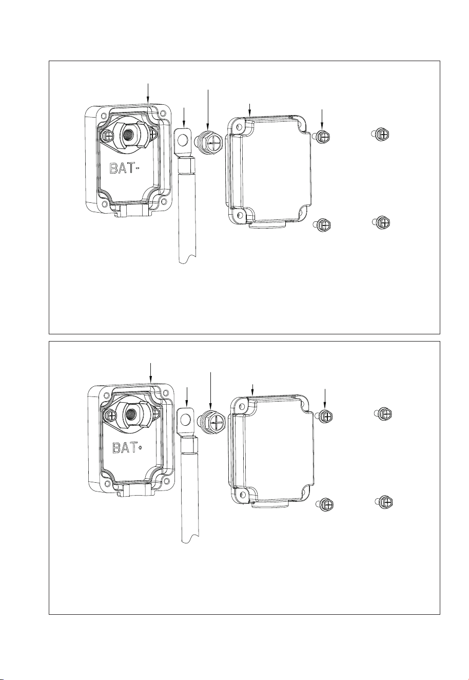
1
2
3
4
5
Max. Torque: 6N m
Max. Torque: 1.2N m
1. Inverter BAT- terminal (Black)
2. Black battery power cable (BAT-)
3. M8*12 screws
4. Black protection cover (BAT-)
5. M4*12 screws
Max. Torque: 6N m
Max. Torque: 1.2N m
1. Inverter BAT+ terminal (Red)
2. Red battery power cable (BAT+)
3. M8*12 screws
4. Red protection cover (BAT+)
5. M4*12 screws
1
2
3
4
5
Figure 5-9-3
Figure 5-9-4
JUST POWER ON34
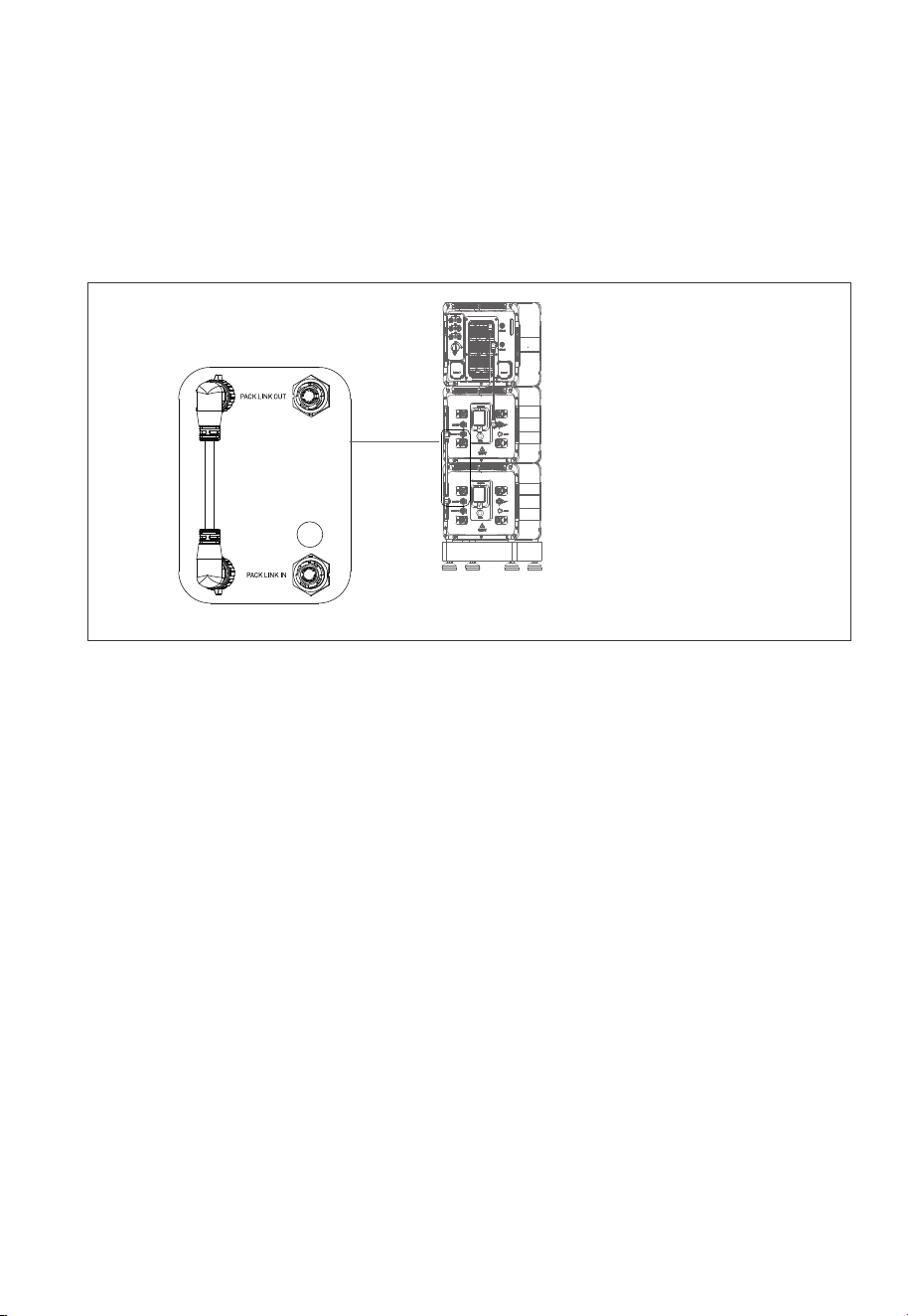
3.5.4 Communication Cable
Step1:
To achieve communication between two B500 battery packs, a communication
cable is required. Plug one end of the cable to the B500 Link-in port, and the other
to the upper B500’s Link-out port. See Figure 5-10 “①”.
Figure 5-10
1
JUST POWER ON 35
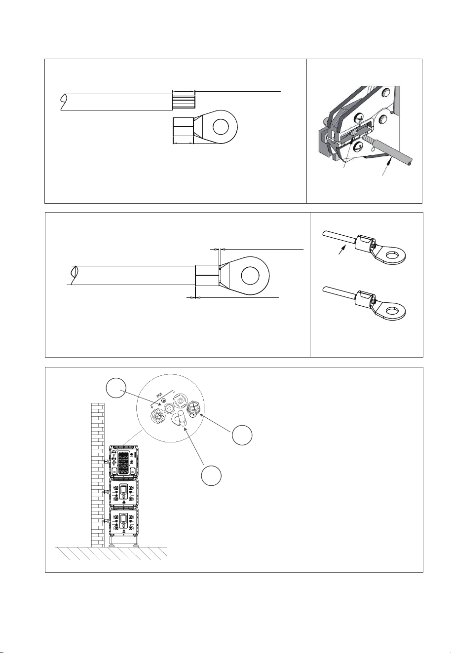
L2 is 3mm longer than L1
5-11-1
L2=L1+3mm
L1
5-11-2 5-11-3
1
2
3
1 . M5×10 screws
2. OT terminal
3. PV grounding pole
L3≥2mm
L4≥1mm
Visible wire
Qualified
Wire even or bulge
up to 1mm
Figure 5-11-3 Grounding Connection
Terminal block
Wire
JUST POWER ON36

4.1 Preliminary Check
Check the followings before first use.
• Confirm that all components of the system are installed according to specific
requirements.
• Make sure the PV+/PV- and BAT+/BAT- cables are connected with correct polarity
and proper voltage.
• Switch off all AC and DC circuit breakers.
• Circuit breakers should be selected according to the requirements of this manual
and local regulations.
• Make sure grid and load cables are held firmly in place.
• All safety signs and warning labels shall be firmly attached and clearly visible when
needed.
4. System Check
4.2 Commissioning/Startup
Step 1: Switch on the DC circuit breakers on inverter.
Step 2: Switch on the DC circuit breakers on B500 battery packs. Press and hold the
power button on any B500 till the indicator on the button light up green.
Step 3: Wait for about 40 seconds till the inverter indicator keeps steady green.
Step 4: Switch on the AC circuit breakers connected to the inverter GRID terminal.
Step 5: Power on the system via BLUETTI App. For details, please refer to BLUETTI
App Instructions.
Step 6: Check the output voltage of BACKUP terminal.
Step 7: Switch on the AC circuit breakers connected to the inverter BACKUP
terminal.
Step 8: Check the inverter system status through the App.
JUST POWER ON 37

4.3 Decommissioning/Shutdown
Step 1: Turn off the AC power on BLUETTI App.
Step 2: Switch off the AC circuit breakers connected to the inverter GRID and
BACKUP terminals.
Step 3: Switch off the inverter PV breaker.
Step 4: Press the power button on any B500 till the indicator on the button flashes
green.
Step 5: The indicator continues to flash.
Step 6: When the indicator is off, B500 battery packs turn off.
Step 7: Switch off main switches for all B500 and the inverter powers off.
Warning
There is still residual voltage after the ESS is powered off, which
may cause electric shock or burns. Please wait at least 30
minutes before operating the system.
Warning
JUST POWER ON38

5.1 Download the App
Scan the QR code below to download the BLUETT App, or search for "BLUETT!" in the
App Store or Google Play.
Supported operating systems: iOS 11.0 or above, Android 8.0 or above.
5. Monitoring and setting
5.2 Binding
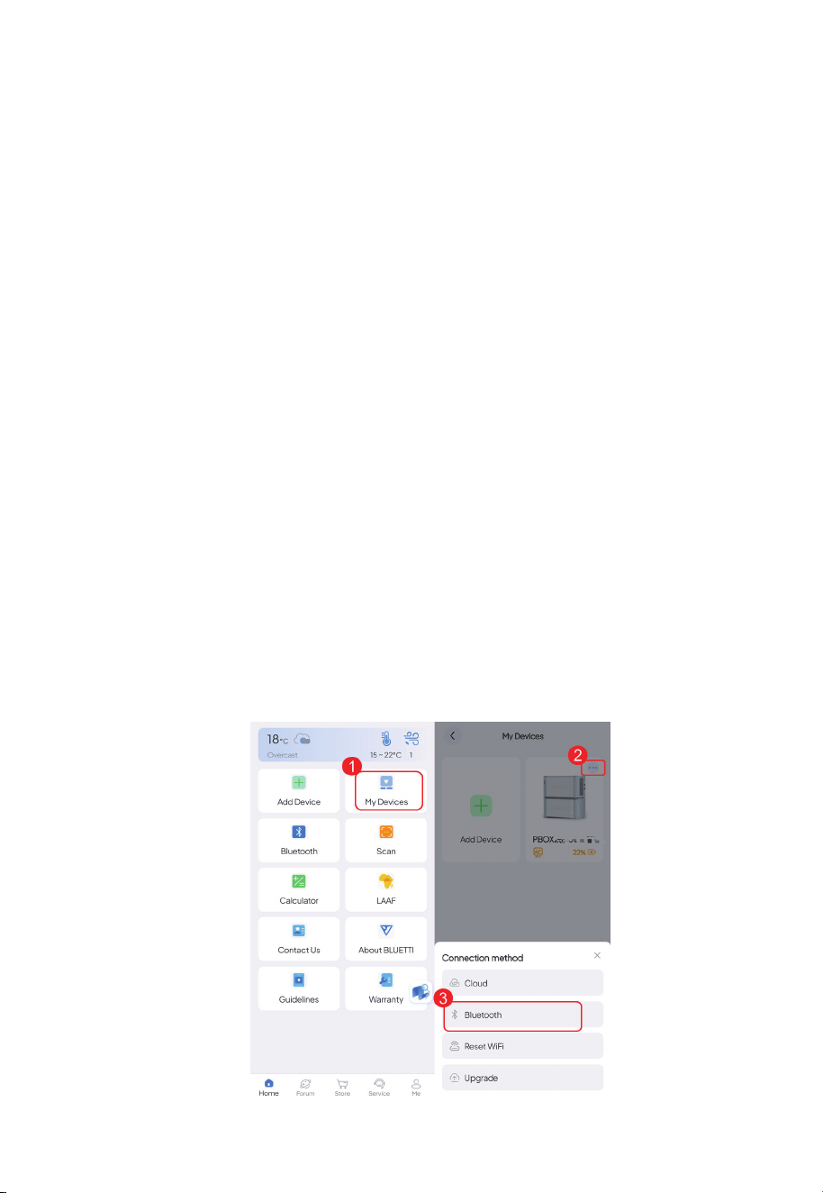
5.2.1 Bluetooth
1. Tap Add Device on the Home page, or tap My Devices > Add Device > Add Manually.
2. On the Bind page, select your device from the Available Devices list, and tap OK to
complete the binding.
3. You can view the bound devices on the My Devices page.
Note: Make sure you’ve enabled Bluetooth and location service (e.g. GPS) on your
phone. If you can’t find your device, get closer and Swipe down to refresh the list
(recommended range: 5m).
JUST POWER ON 39
5.3 Connection
5.3.1 Bluetooth Connection
Note: Make sure your device is powered on with Bluetooth enabled, and you've enabled
Bluetooth and location service (e.g. GPS) on your phone. For a stable connection, keep your
phone and device close together (recommended range: 5m). If you can't find your
device, get closer and Swipe down to refresh the list.
1. Tap My Devices on the Home page.
2. Tap in the upper right corner of the device you want to connect.
3. Tap Bluetooth to connect.
4. You'll be directed to the operation status page upon successful connection.
5.2.2 Serial Number
1. Tap Add Device on the Home page.
2. At the bottom of the Bind page, tap Add Manually.
3. Enter the device model and serial number.
4. Tap OK to complete the binding.
5.2.3 QR Code
1.Tap the Scan on the Home page, or tap My Devices > Add Device > Scan.
2.Scan the QR code on your device.
JUST POWER ON40
5.3.2 Cloud Connection
To get started, you need to configure the network first.
Note:
• Place your device within the range of an available WiFi network. Also,double-check
that your mobile device has a strong and stable network signal.
• The BLUETTI products support 2.4GHz WiFi only.
Configure the network
If you have connected your device via Bluetooth, please follow the steps below:
1. Tap in the upper right corner of the operation status page to enter the setting page.
2. Tap Network settings.
3. Change the configuration in the pop-up and SAVE it.
If you need to change to another WiFi network, please follow the steps below:
1. Go to the My Devices page and tap in the upper right corner of the device you
want to connect.
2. Tap Reconfigure WiFi.
3. Fill in the related network information and SAVE it.
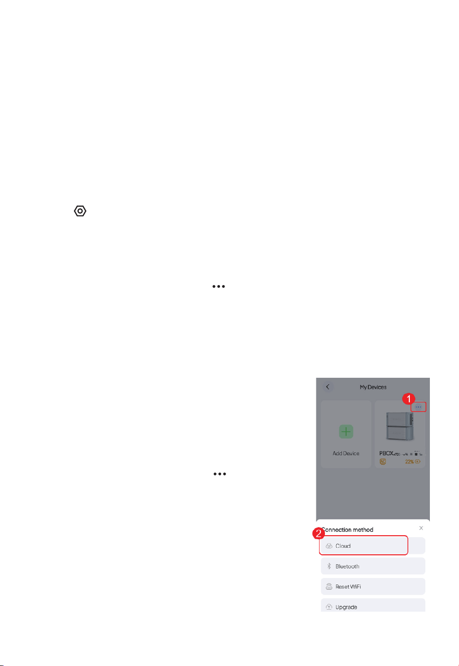
5.3.3 Connect to the device
Once the app is connected to the device via WiFi, you can
manage your device
from anywhere at any time, as long as your mobile phone
has internet access and your device maintains a stable
WiFi connection.
1. Go to the My Devices page, and tap in the upper
right corner of the device you want to connect.
2. Tap Cloud to connect.
3. The app will jump to the operation status page when
the connection is successful.
Note: If you've set the default connection mode as Cloud,
you can also establish a WiFi connection by directly
tapping on the device image.
JUST POWER ON 41
5.4 Real-time Monitoring
The app shows you important details like the current battery level, energy flow status,
and other key metrics so you can keep track of how your battery is doing. Additionally,
in case of any malfunctions or alarms, you can view real-time alerts so that you can take
immediate action to deal with any issues in a timely manner.
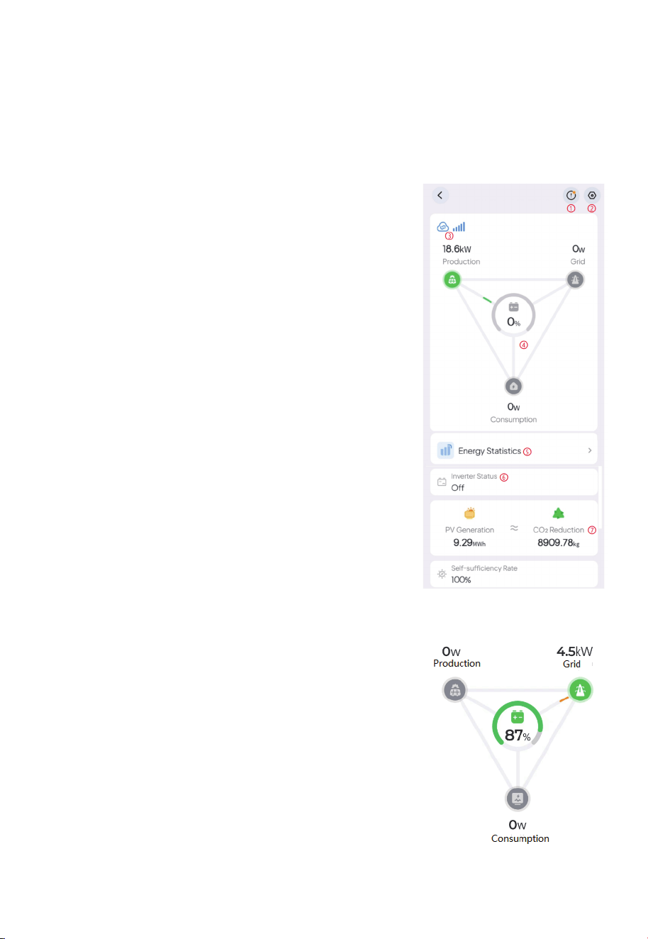
5.4.1 Operation Status
Connect the app to your battery via Bluetooth or WiFi,
and you'll be directed to the operation status page.
Please refer to Binding for details
①Tap to check the current alarm(s) and alarm history.
② Tap to check and change system settings, like
System Switch, Working Mode, Device Sharing,
Advanced Settings, etc.
③Bluetooth / WiFi connection successful.
④Energy Flow Status Please refer to Energy Flow
Status for details.
⑤ Energy Statistics Tap to view the energy data by
day, month, year, or up to the current date. Please
refer to Energy Statistics for details.
⑥Inverter Status Please refer to Inverter Status for
details.
⑦PV Generation & CO2 Reduction Check out the total
solar energy generated and carbon emissions saved
by the battery over time
5.4.2 Energy Flow Status
The animation gives you a simple way to understand
how energy is flowing
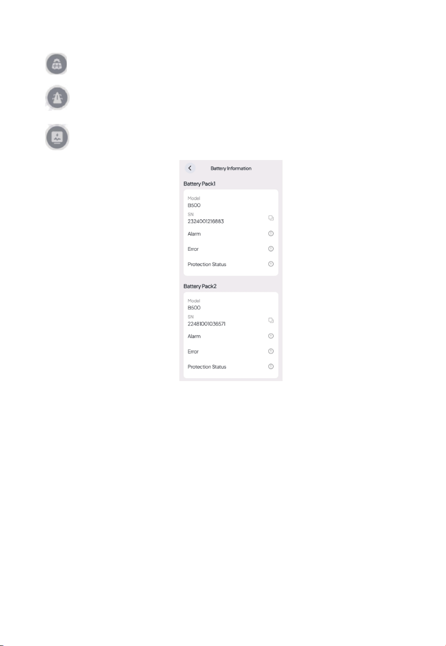
87% SoC (State of Charge). It indicates the remaining
battery level. Tap to check the battery fault and
protection status, as shown below.
JUST POWER ON42
:PV generation. It shows how much power the Inverter is drawing from your
rooftop solar or solar panel(s). Tap to view more details
:Grid charging or feeding. It shows how much power the inverter is drawing
from or feeding back into the grid. Tap to view more details
:Load consumption. It shows how much power is supplying to your household
appliance. Tap to learn more about where the power is going.
6. System Disposal
5.1 Recycle the B500 Battery Pack
When the battery pack reaches the end of its lifespan,itmust be safely and carefully
disposedofby the provisions of local laws andregulations.
Please contact our company for further assistance if the battery pack is
a. Leaked or damaged.
b. Severely degraded in performance.
c. To be replaced or not intended for further use.
JUST POWER ON 43

7. Specifications
Battery parameters
Item
Type of battery
Cell capacity
Battery capacity
Battery Voltage
Rated capacity
Availablecapacity
Over voltage protection for single cell
low-voltageprotection for single cell
Max. charge voltage
Lowest discharge voltage
Max. Charge current
Max. Discharge current
DC-DC RTE
IP Degree
Dimension(L×W×H)
Weight
Work temperature
Rating Note
LiFePO
4
50Ah
50Ah
99.2V
4960Wh
4464Wh
3.7V
2.5V
108.5V
86.8V
25A
50A
95.8%
IP65
L636mm×W325mmmm×H338mm
58Kg
-20°C-50°C
1P31S
3.2V×31
25℃,
Charge 0.5C/3.6V/0.05C
Discharge 1.0C/2.5V
90%DOD,25°C,
0.5Ccharge,
1.0C discharge
3.5V×31
2.8V×31
JUST POWER ON44

8. FAQs (Frequently Asked Questions)
What should I do if the SoC readings are inaccurate?
If you notice significant momentary fluctuations in the SoC, try performing two
complete charge and discharge cycles on your inverter. This will help recalibrate
the system and restore accurate SoC readings.
Q1:
A1:
JUST POWER ON 45


For more information, please visit:
@bluetti.au
@ bluetti_inc
@bluetti_australia
@ BLUETTI Support
@ BLUETTI Official
SHENZHEN POWEROAK NEWENER CO., LTD.
Address: F19, BLD No.1, Kaidaer, Tongsha Rd No.168, Xili Street, Nanshan,
Shenzhen, China
Web: https//www.bluettipower.com
Customer Service(AU)
Email: sale-au@bluettipower.com
Address: Unit 15, 25 Gibbes Street Chatswood NSW 2067

P/N:17.0303.0808-00A0