i
Programmable DC Power
Supply&Multimeter Manual

ii
Table of Contents
1. General Safety Requirements .........................................................1
1.1 Measurement Category
....................................................................................................2
2. Safety Terms and Symbols .............................................................. 3
3. Quick Review .................................................................................... 4
3.1 Panel and Interface
...........................................................................................................4
3.1.1 Front Panel
..............................................................................................................4
3.1.2 Rear Panel
.............................................................................................................. 6
3.1.3 User Interface
......................................................................................................... 6
3.2 General Inspection
............................................................................................................ 7
3.3 Power Inspection
...............................................................................................................8
3.4 Output Inspection
.............................................................................................................. 8
4. Panel Operation.............................................................................. 10
4.1 Use of power supply
....................................................................................................... 10
4.2 Turn On/Off the Channel Output
...................................................................................10
4.3 Set the Output Voltage/Current
.....................................................................................10
4.4 Over Voltage/Current Protection
...................................................................................10
4.5 Memory key shortcut settings
....................................................................................... 11
4.5.1 Edit
......................................................................................................................... 11
4.5.2 Quick output
..........................................................................................................12
4.6 Set List Waveform Output
..............................................................................................12
4.6.1 List waveform editing
.......................................................................................... 13
4.6.2 List waveform output
........................................................................................... 14
4.7 Set Automatic Output at Power-on
...............................................................................15
4.8 Use of Multimeter
............................................................................................................ 16
4.8.1 Multimeter Interface
.............................................................................................16
4.8.2 Multimeter Measurement
....................................................................................16
4.9 Display(DISP) ............................................................................................................. 22
4.9.1 Number
.................................................................................................................. 22
4.9.2 Curve
......................................................................................................................22
4.9.3 Interface of Multimeter Measurement
.............................................................. 22
4.9.4 Dual-display Measurement Interface of Power Supply and Multimeter
..... 23
5. Troubleshooting .............................................................................. 24
6. Technical Specification .................................................................. 25
7. Appendix .......................................................................................... 29
7.1 Appendix A:Accessories ..............................................................................................29
7.2 Appendix B: General Care and Cleaning
.................................................................... 29
7.3 Appendix C: Download link and QR code
...................................................................31

1.General Safety Requirements
1
1. General Safety Requirements
Before use, please read the following safety precautions to avoid any
possible bodily injury and to prevent this product or any other connected
products from damage. To avoid any contingent danger, ensure this
product is only used within the ranges specified.
Only a qualified person should perform internal maintenance.
To avoid Fire or Personal Injury:
Use Proper Power Cord. Use only the power cord supplied with the
product and certified to use in your country.
Product Grounded. This instrument is grounded through the power cord
grounding conductor. To avoid electric shock, the grounding conductor
must be grounded. The product must be grounded properly before any
connection with its input or output terminals.
Check all Terminal Ratings. To avoid fire or shock hazard, check all
ratings and markings on this product. Refer to the user manual for more
information about ratings before connecting to the instrument.
Do not operate without covers. Do not operate the instrument with
covers or panels removed.
Use the Proper Fuse. Use only the specified type and rating fuse for this
instrument.
Avoid exposed circuit. Be careful when working on exposed circuitry to
avoid risk of electric shock or other injury.
Do not operate if any damage. If you suspect damage to the instrument,
have it inspected by qualified service personnel before further use.
Use your instrument in a well-ventilated area. Please keep well
ventilated and inspect the intake and fan regularly.
Do not operate in damp conditions. To avoid short circuiting to the
interior of the device or electric shock, please do not operate in a humid
environment.
Do not operate in an explosive atmosphere. To avoid damages to the
device or personal injuries, it is important to operate the device away from
an explosive atmosphere.
Keep product surfaces clean and dry. To avoid the influence of dust or
moisture in air, please keep the surface of device clean and dry.
Do not apply more than the rated voltage (as marked on the multimeter)
between terminals, or between terminal and earth ground.
When measuring current, turn off the circuit power before connecting the
multimeter in the circuit. Remember to place the multimeter in series with
the circuit.
Use caution when working above 60 V DC, 30 V AC RMS, or 42.4 V peak.
Such voltages pose a shock hazard.

1.General Safety Requirements
2
When using the test leads, keep your fingers behind the finger guards on
the test leads.
Disconnect circuit power and discharge all high-voltage capacitors before
testing resistance, continuity, diodes, or capacitance.
Use the proper terminals, function, and range for your measurements.
When the range of the value to be measured is unknown, set the rotary
switch position as the highest range, or choose the auto ranging mode. To
avoid damages to the multimeter, do not exceed the maximum limits of the
input values shown in the technical specification tables.
Connect the common test lead before you connect the live test lead. When
you disconnect the leads, disconnect the live test lead first.
Before changing functions, disconnect the test leads from the circuit under
test.
1.1 Measurement Category
The multimeter has a safety rating of 600 V, CAT II.
Measurement category definition
Measurement CAT I applies to measurements performed on circuits not
directly connected to the AC mains. Examples are measurements on circuits
not derived from the AC mains and specially protected (internal) mains-
derived circuits.
Measurement CAT II applies to protect against transients from
energy-consuming equipment supplied from the fixed installation, such as TVs,
PCs, portable tools, and other household circuits.
Measurement CAT III applies to protect against transients in equipment in
fixed equipment installations, such as distribution panels, feeders and short
branch circuits, and lighting systems in large buildings.
Measurement CAT IV applies to measurements performed at the source of
the low-voltage installation. Examples are electricity meters and
measurements on primary over current protection devices and ripple control
units.
2.Safety Terms and Symbols
3
2. Safety Terms and Symbols
Safety Terms
Terms in this manual (The following terms may appear in this manual):
Warning: Warning indicates conditions or practices that could result
in injury or loss of life.
Caution: Caution indicates the conditions or practices that could
result in damage to this product or other property.
Terms on the product. The following terms may appear on this product:
Danger: Indicates an immediate hazard or injury possibility.
Warning: Indicates a possible hazard or injury.
Caution: Indicates potential damage to the instrument or other property.
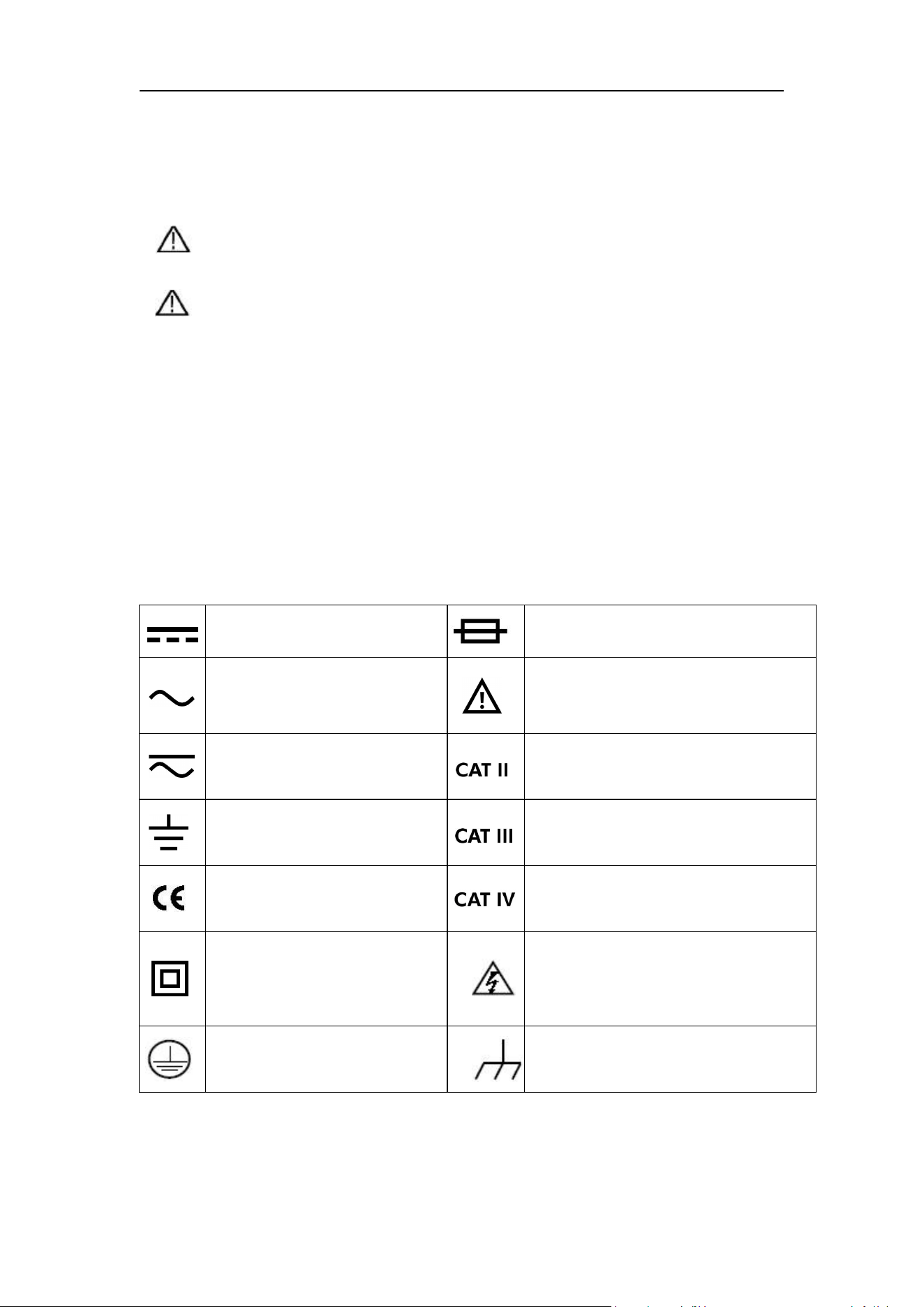
Safety Symbols
Symbols on the product. The following symbols may appear on the
product:
Direct current (DC)
Fuse
Alternating current (AC)
Caution, risk of danger (refer to
this manual for specific Warning or
Caution information)
Both direct and alternating
current
Category II overvoltage protection
Public Ground
Category III overvoltage protection
Conforms to European
Union directives
Category IV overvoltage protection
Equipment protected
throughout by double
insulation or reinforced
insulation
Hazardous Voltage
Protective Earth Terminal
Chassis Ground
3.Quick Review
4
3. Quick Review
3.1 Panel and Interface
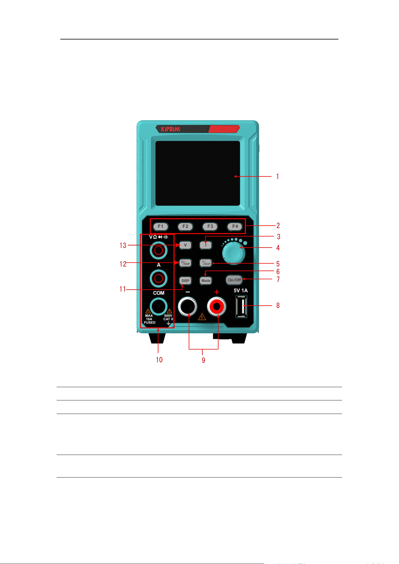
3.1.1 Front Panel
Figure 3- 1 Front Panel Overview
1
Display screen
Displays user interface.
2
F1-F4 Keys
Setting buttons of sub-menu options.
3
Current Key
Under power supply state: Press movable cursor to
set current and edit other parameters;
Under multimeter state: Press the button to switch
between AC/DC current states.
4
Knobs
Select main menu or change a specific value.
Press the button for confirmation.
3.Quick Review
5
5
Setting button of
overcurrenting/swit
ching
Under power supply state: Press movable cursor to
set overcurrent protection and edit other
parameters;
Under multimeter state: Press the button to enter
manual range setting state, and press it again to
switch the range of current measurement
parameters. (Note: Manual range setting functions
not available for capacitors, diodes and current).
6
Mode Key
Under dual display mode, press this button to
switch the controlling state of power supply and
multimeter.
7
On/Off Key
Enable/disable channel output setting.
8
USB interface
USB charging port (no reading/writing function)
5V/1A charging port
9
Channel output
terminal
Output connections for channels.
10
Multimeter input
Input connections for multimeter channels.
11
DISP Key
The interface will show switch button.
12
Multimeter
measurement
switching Key
/overvoltage setting
Key
Under multimeter state: Press the button to switch
the measuring state of multimeter resistance,
on-off, diode and capacitance;
Under power supply state: Press movable cursor to
set overvoltage protection and edit other
parameters.
13
Voltage Key
Under power supply state: Press movable cursor to
set voltage and edith other parameters;
Under multimeter state: Press the button to switch
between AC/DC voltage state.
Button light instruction
key: The key lights up when the channel turns on.
3.Quick Review
6
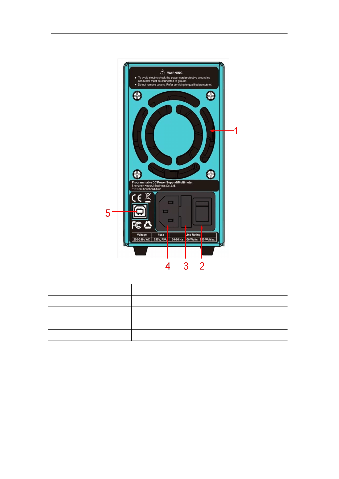
3.1.2 Rear Panel
Figure 3- 2 Rear Panel Overview
1
Air Vent
Air vent.
2
Power Button
Turn on/off the instrument.
3
Fuse
Power fuse.
4
AC Power Input Jack
AC power input interface.
5
Device USB Port
Update the firmware, PC software control port.
3.1.3 User Interface
Power supply mode User Interface
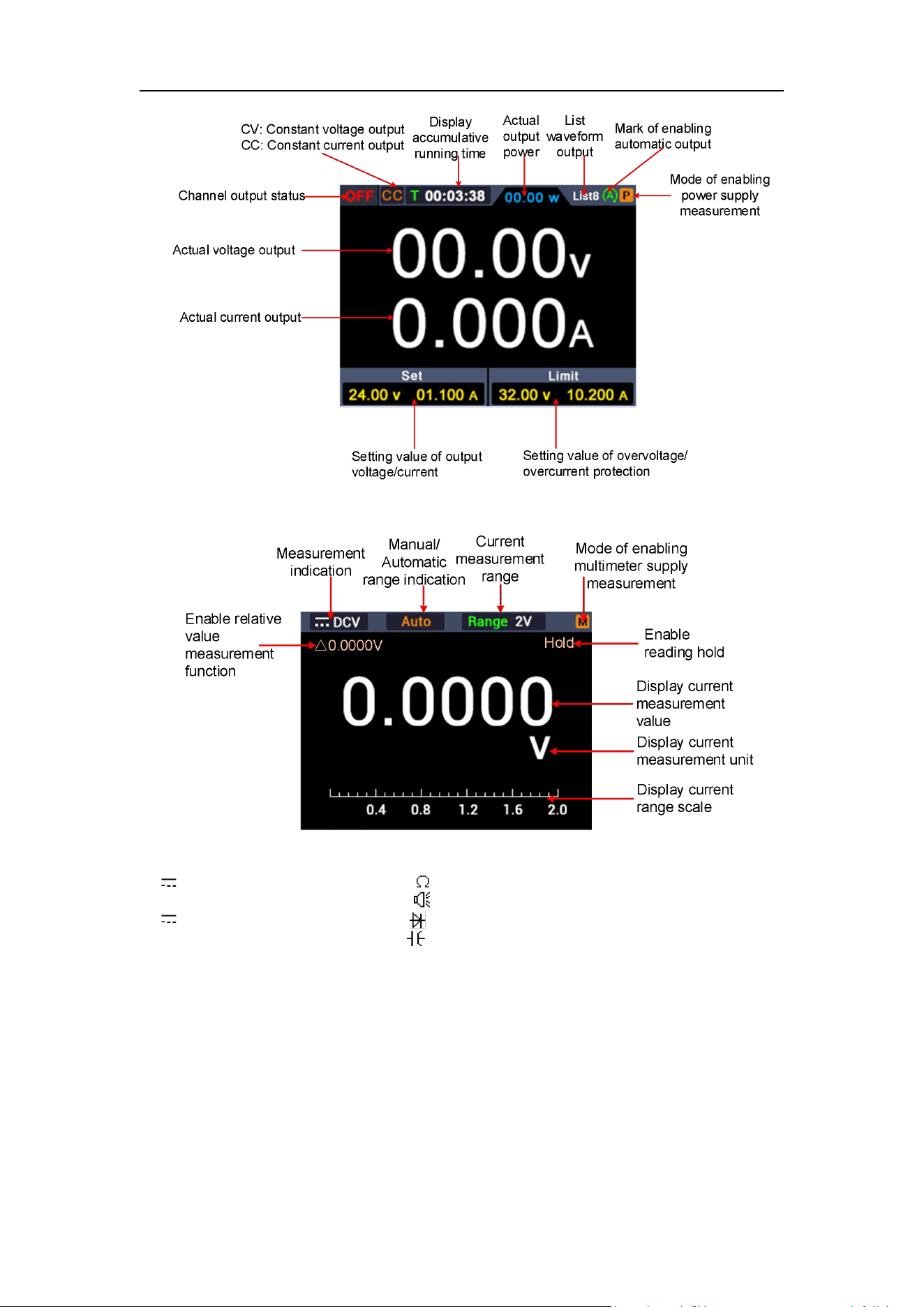
3.Quick Review
7
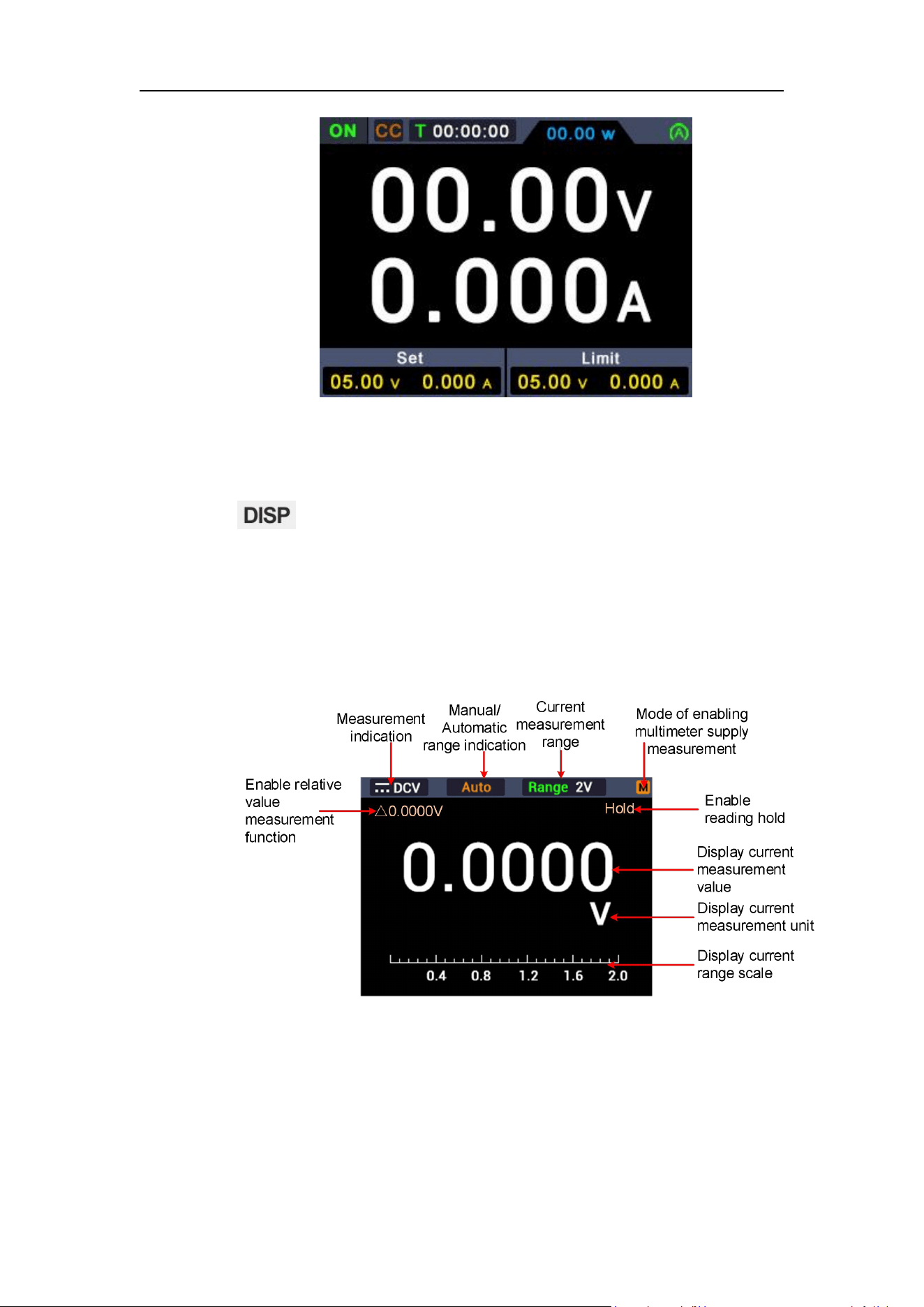
Multimeter mode User Interface
Measurement indication:
DCV------ DC voltage measurement Res------ Resistance measurement
~
DCV------ AC voltage measurement Cont------ On-off measurement
DCI------ DC current measurement Diode------ Diode measurement
~
DCI------ AC current measurement Cap------ Capacitance measurement
Figure 3- 3 User Interface
3.2 General Inspection
After you get a new power supply, it is recommended that you should make a
check on the instrument according to the following steps:
1. Check whether there is any damage caused by transportation.
3.Quick Review
8
If it is found that the packaging carton or the foamed plastic protection
cushion has suffered serious damage, do not throw it away first till the
complete device and its accessories succeed in the electrical and
mechanical property tests.
2. Check the Accessories
The supplied accessories have been already described in the
"Appendix A: Enclosure" of this Manual. You can check whether there is
any loss of accessories with reference to this description. If it is found
that there is any accessory lost or damaged, please get in touch with
the distributor of our responsible for this service or our local offices.
3. Check the Complete Instrument
If it is found that there is damage to the appearance of the instrument, or
the instrument can not work normally, or fails in the performance test,
please get in touch with our distributor responsible for this business or
our local offices. If there is damage to the instrument caused by the
transportation, please keep the package. With the transportation
department or our distributor responsible for this business informed
about it, a repairing or replacement of the instrument will be arranged by
us.
3.3 Power Inspection
(1) Use the power cord supplied with the accessories to connect the
instrument to the AC power.
Warning:
To prevent electric shock, make sure that the instrument is
properly grounded.
(2) Press the power button on the front panel, the button light will be on, and
the startup screen will be displayed on the screen.
3.4 Output Inspection
Output inspection is to ensure that the instrument can achieve its rated outputs
and properly respond to operation from the front panel. For the procedures
below, it is suggested that you read "Turn On/Off the Channel Output" on page
10 and "Set the Output Voltage/Current" on page 10.

3.Quick Review
9
3.4.1 Voltage Output Inspection
The following steps verify basic voltage functions without load:
(1) When the instrument is under no load, select a channel and ensure the
output current setting for this channel is not at zero.
(2) Turn on the channel output, then ensure the channel is in Constant
Voltage output mode.
(3) Set some different voltage values on this channel; check if the actual
voltage value displayed is close to the set voltage value, and also that the
actual current value displayed is nearly to zero.
(4) Check that if the output voltage can be adjusted from zero to the maximum
rating,When it is set to the maximum or minimum, a beep is heard,
indicating that the limit has been reached.
3.4.2 Current Output Inspection
The following steps check basic current functions with a short across the
power supply's output:
(1) Connect a short across (+) and (-) output terminals with an insulated test
lead on this channel. Use a wire size sufficient to handle the maximum
current.
(2) Set the output voltage to the maximum rating on this channel.
(3) Turn on the channel output. Ensure the channel you used is in Constant
Current output mode.
(4) Set some different current values on this channel; check if the actual
current value displayed is close to the set current value, and to check if the
actual voltage value displayed is nearly zero.
(5) Check that if the output current can be adjusted from zero to the maximum
rating, When it is set to the maximum or minimum, a beep is heard,
indicating that the limit has been reached.
(6) Turn off the channel output and remove the short circuit from the output
terminals.
4
.
Panel Operation
10
4.
Panel Operation
4.1 Use of power supply
Press button on the front panel to switch to power interface. Power
supply operation mode will be enabled, when P icon appears at the upper
right corner of the screen.
4.2 Turn On/Off the Channel Output
Press the key to turn on/off the channel.
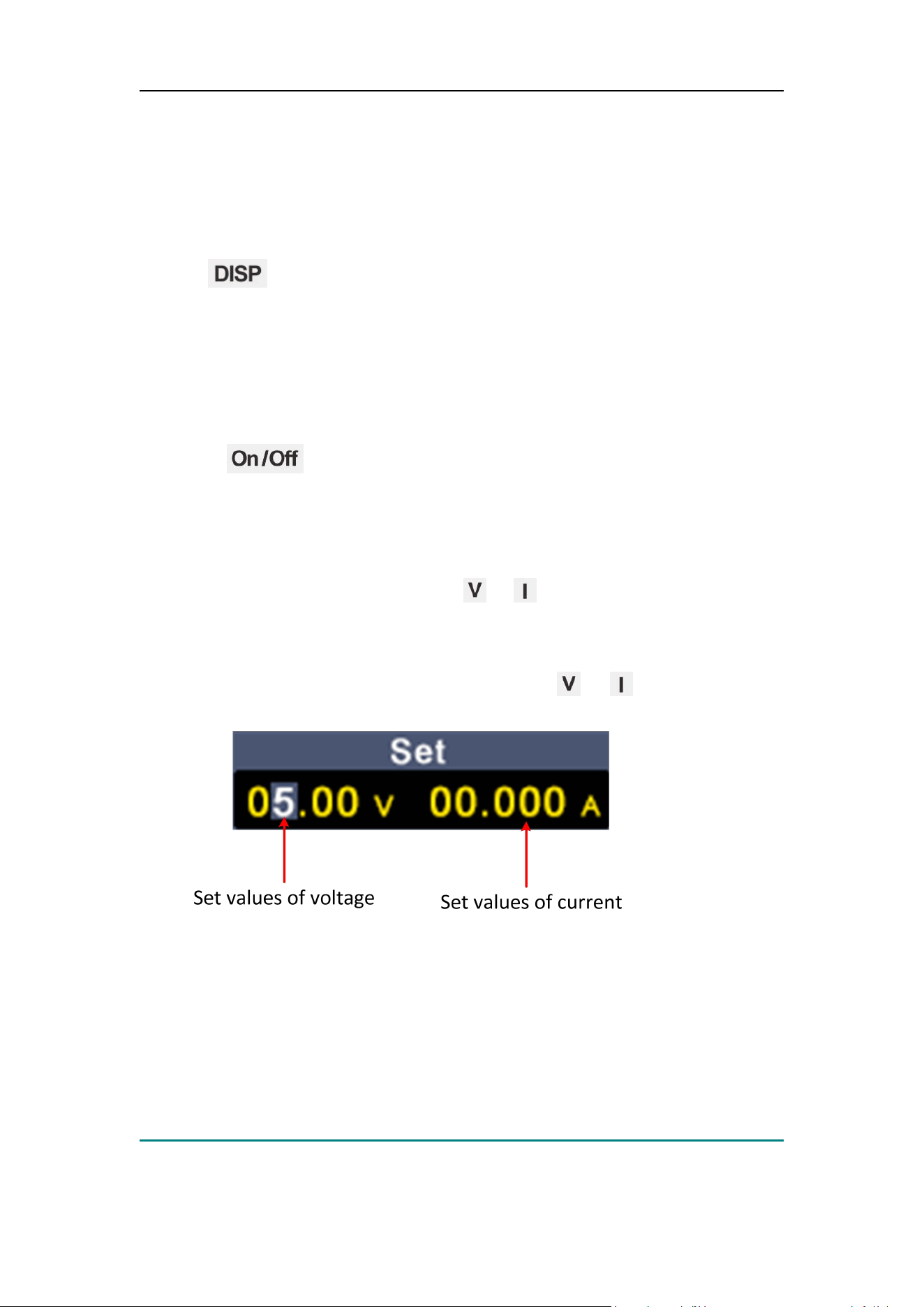
4.3 Set the Output Voltage/Current
In the channel setting area, press the / key to move the gray cursor
between different positions of the voltage/current value. After pressing the
output voltage/current setting value, turn the knob to change the value of the
current cursor, and press the knob or press the / key to move the
cursor.
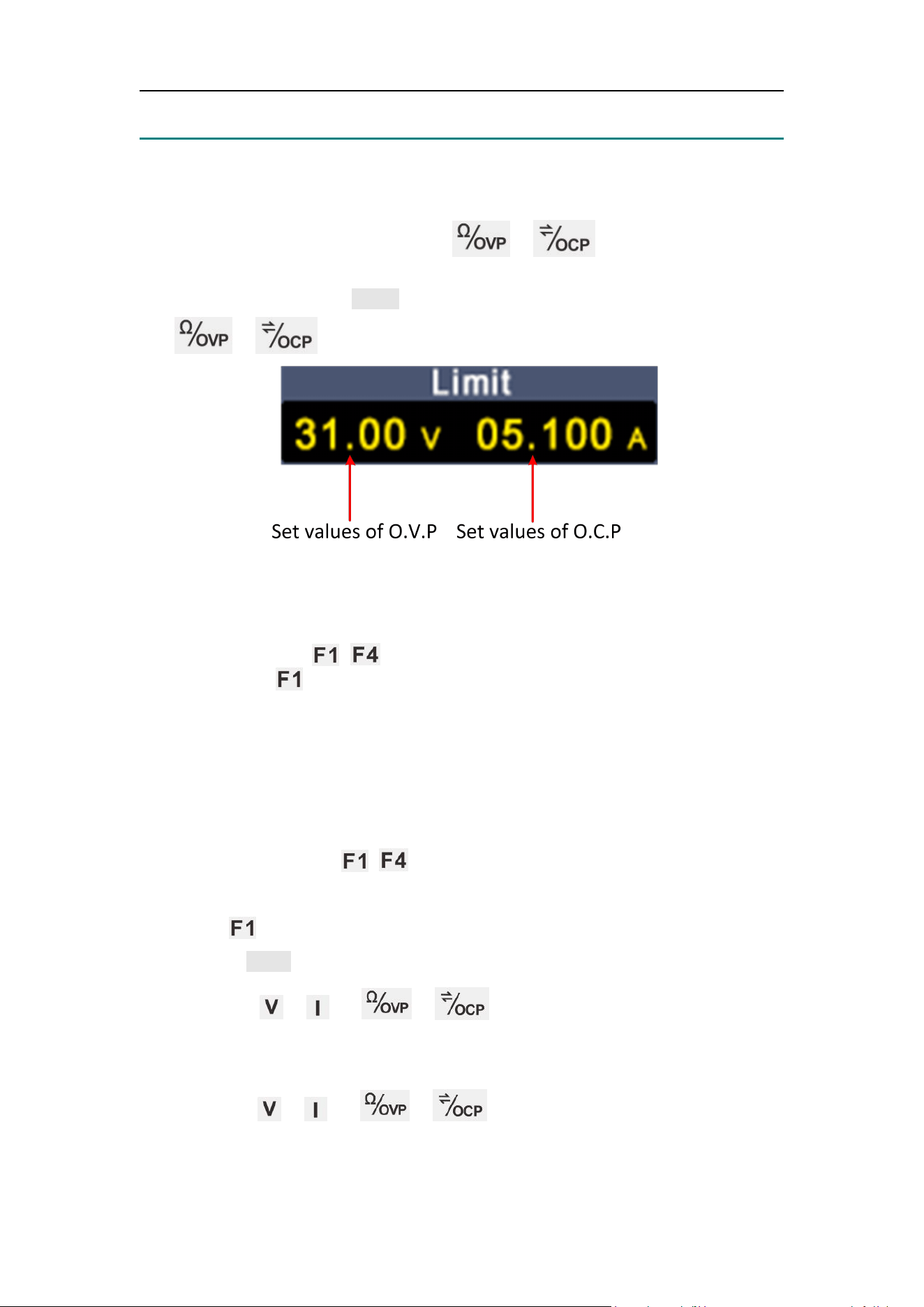
4.4 Over Voltage/Current Protection
Overvoltage protection (O.V.P) or overcurrent protection (O.C.P): after the
output is turned on, once the output voltage/current reaches the set value of
O.V.P/O.C.P, the instrument will cut off the output, a warning will show on the
screen.
Note:
When the instrument disables the output due to protection, after you make
4
.
Panel Operation
11
some adjustments, the channel must be restarted to output normally.
This function can keep the power output from exceeding the load rating to
protect the load.
In the channel setting area, press the / keys to move the blue
cursor between parameters. After selecting the overvoltage/overcurrent
protection value, turn the Knob to change the current cursor value, and press
the / direction key to move the cursor position..
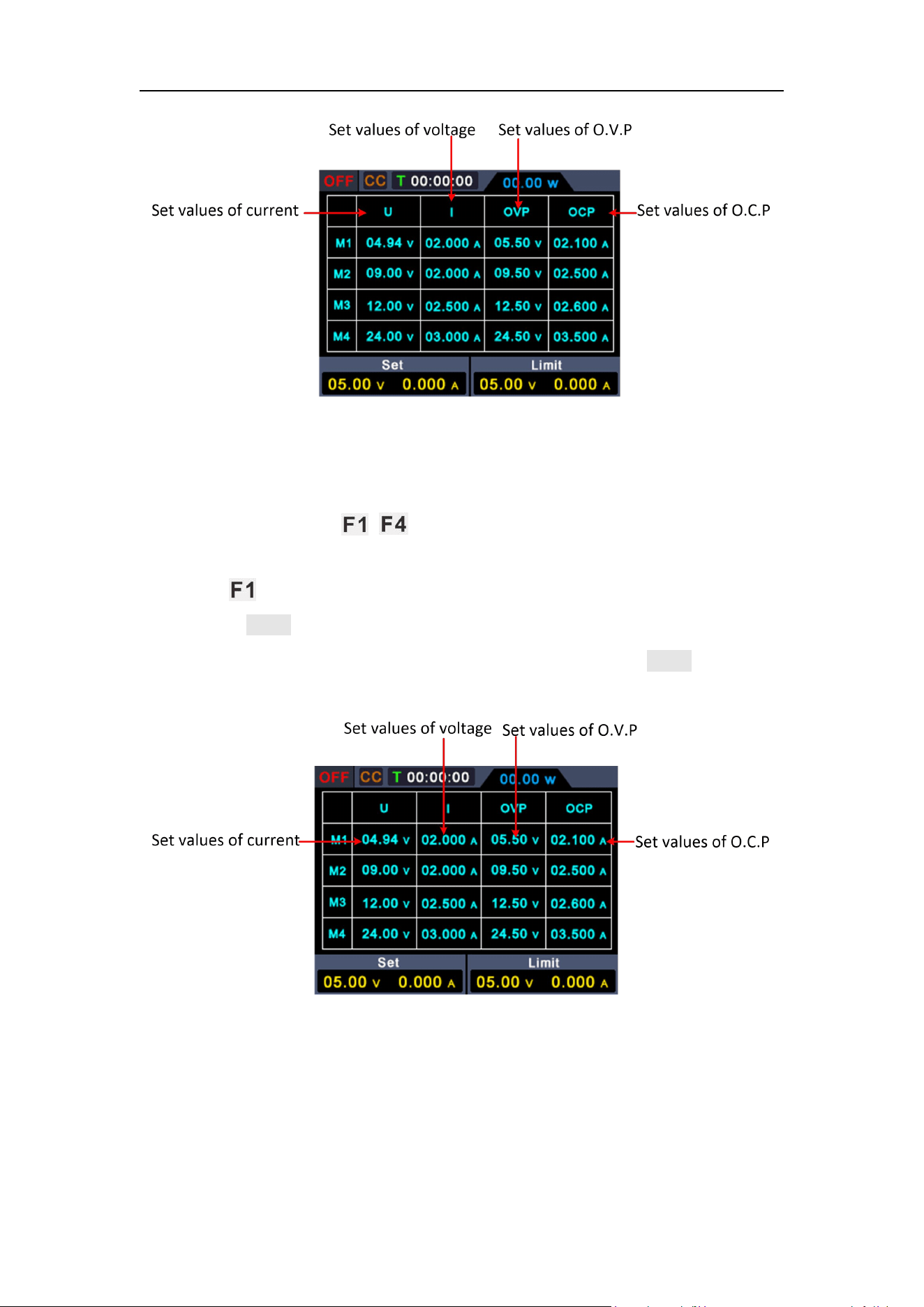
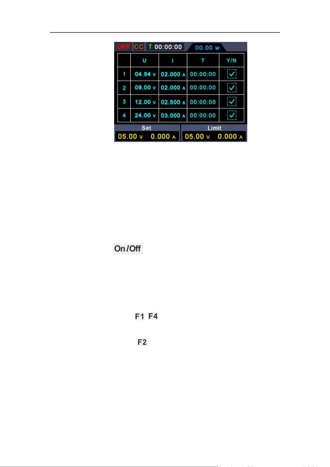
4.5 Memory key shortcut settings
Press any button of ~ on the front panel under power supply interface
and then press button to pop up options for storing 4 groups of channel
parameters, M1, M2, M3 and M4 respectively, which can be used for shortcut
output.
4.5.1 Edit
To edit the channel parameters of M1 to M4, follow these steps:
(1) Press any button of ~ on the front panel, and the power supply
sub-menu will be displayed at bottom of the screen.
(2) Press button and the screen will display shortcut setting interface.
(3) Turn the knob to move the purple selection box.
(4) Press the / / / key to set the voltage / current /
over voltage protection / over current protection value.
(5) Turn the knob to change the value of the current cursor, press the knob or
press the / / / key to move the cursor.
4
.
Panel Operation
12
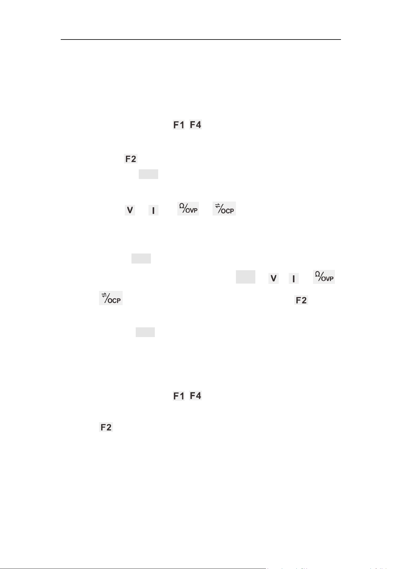
4.5.2 Quick output
To output a set of parameters from M1 to M4, follow these steps:
(1) Press any button of ~ on the front panel, and the power supply
sub-menu will be displayed at bottom of the screen.
(2) Press button and the screen will display shortcut setting interface.
(3) Turn the knob to move the purple selection box.
(4) After selecting a group of parameters, press and hold the knob to confirm
they have been exported from the current setting.
4.6 Set List Waveform Output
The user can edit and output the waveform. A set of waveforms contains 10
editable points. The four editable parameters of each point include output
voltage, output current, waveform duration and whether the point is selected.
When the editing is completed, the instrument can output the expected
4
.
Panel Operation
13
waveform according to the time sequence edited by the user.
4.6.1 List waveform editing
To edit the List output waveform, the steps are as follows:
(1) Press any button of ~ on the front panel and the power
supply sub-menu will be displayed at bottom of the screen;
(
2
)
Press button to enter “interface of editing List waveform”;
(
3
)
Rotate the knob under non-parameter setting state to move the
purple selection box;
(4) Press / / / buttons to enter parameter
setting state, which is set voltage/ current/ duration/selection state
respectively;
(
5
)
Turn the knob under the parameter setting state to change the
present value of cursor, and press the knob or / / /
buttons to move the cursor position; press the button
to exit parameter setting state;
(
6
)
Press the knob for 3s under non-parameter setting state for
confirmation. After entering the “List waveform output mode”, List n
(n=1~10) will appear at the upper right corner of the screen; switch
back to the main interface at the same time;
(7) Press any button of ~ on the front panel, and the power
supply sub-menu will be displayed at bottom of the screen; press
button to exit “interface of editing List waveform”.
4
.
Panel Operation
14
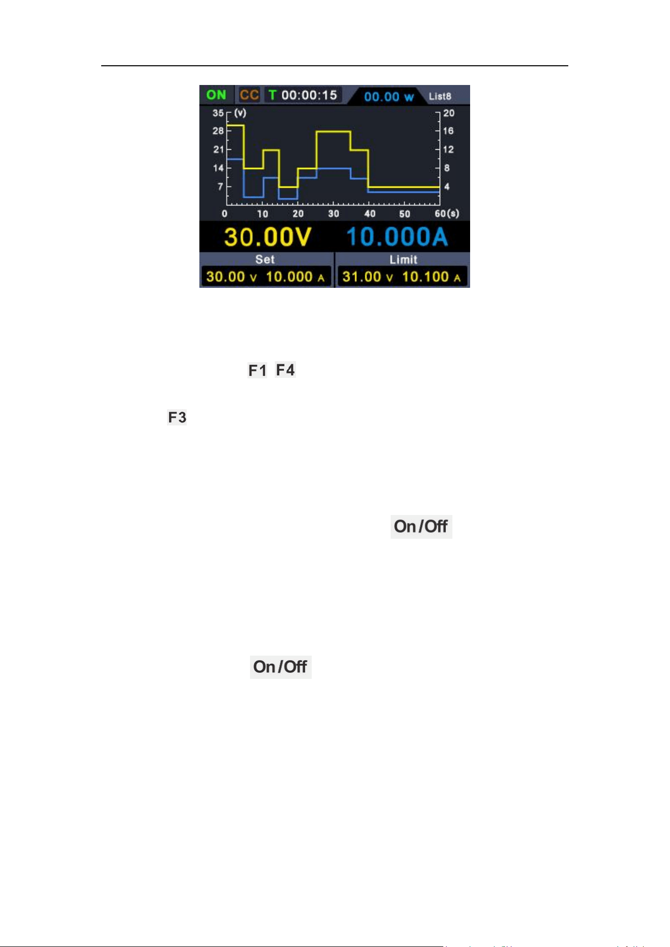
4.6.2 List waveform output
To perform List waveform output, the steps are as follows:
(
1
)
Edit List waveform according to the steps in 4.6.1;
(
2
)
After entering the “List output mode”, the first point of List waveform
pre-output will be displayed at the upper right corner, such as
“List8”;
(
3
)
Press the function button on the front panel for a short
time, and the machine will output according to the List editing time
sequence. Meanwhile, the current List output point and the duration
countdown of this point will be displayed at the status bar on the
upper part of the main interface;
(4) Press any button ~ on the front panel under the List output
mode and the power supply sub-menu will be displayed at bottom of
the screen. Press button to exit the “List output mode”.
4
.
Panel Operation
15
4.7 Set Automatic Output at Power-on
1. Press any button of ~ on the front panel, and the power supply
sub-menu will be displayed at bottom of the screen;
2. Press button, to enable or disable the function of “Auto Output after
Startup”;
When the “Automatic Output after Startup” is enabled, the A mark will
be displayed at the upper right corner of the screen. After power-on
for 3s, the machine will execute the “ ” operation
automatically, and output according to the current output voltage
and output current;
When the “Automatic Output after Startup" is disabled, the machine
will enter standby state after power-on. In such case, user needs to
execute the “ ” operation manually before the machine
is able to output.
4
.
Panel Operation
16
4.8 Use of Multimeter
Press the button on the front panel to switch to the multimeter
interface. Multimeter operation mode will be entered when the M icon is
displayed at the upper right corner of the screen.
4.8.1 Multimeter Interface
4.8.2 Multimeter Measurement
Measurement of DC or AC Voltage
4
.
Panel Operation
17
Warning: Do not measure any voltage of over 1000 Vdc or 750 Vac
rms to avoid instrument damage or electric shock.
Do not apply more than 1000 Vdc or 750 Vac rms between the
common terminal and the earth ground to avoid instrument
damage or electric shock.
DC voltage valve and its polarity can be displayed on the multimeter interface.
A negative DC voltage will be displayed at the left side of display screen in the
form of a “-”.
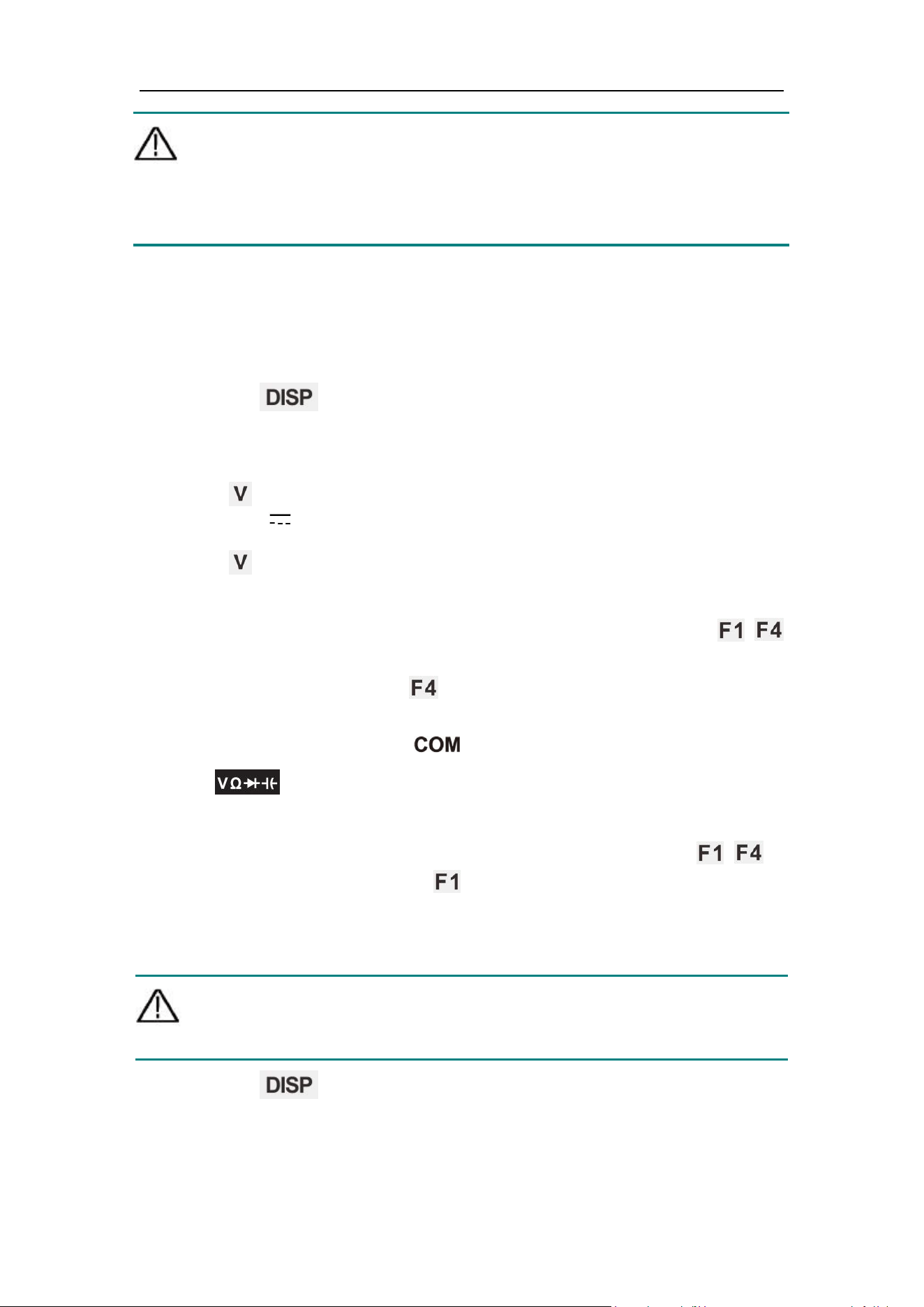
(1) Press the button on the front panel to switch to the multimeter
interface, and the M icon will be displayed at the upper right corner of the
screen.
(2) Press button on the front panel to enter the DC voltage measurement
mode, and DCV will be displayed at the upper left corner of the screen.
Press button to switch to AC voltage measurement mode, and
~
ACV
will be displayed on the screen.
(3) Select gear according to the measured range, press any button of ~
on the front panel, and the multimeter sub-menu will be displayed at
bottom of the screen. Press button to select the mV or V gear
required for voltage measurement.
(4) Insert the black test pen into input terminal and the red test pen
into input terminal respectively.
(5) Connect the other ends of the red and black test pens to the tested point
respectively, and read the displayed value. Press any button of ~ on
the front panel, and then press to enter and switch the manual range
under the current gear.
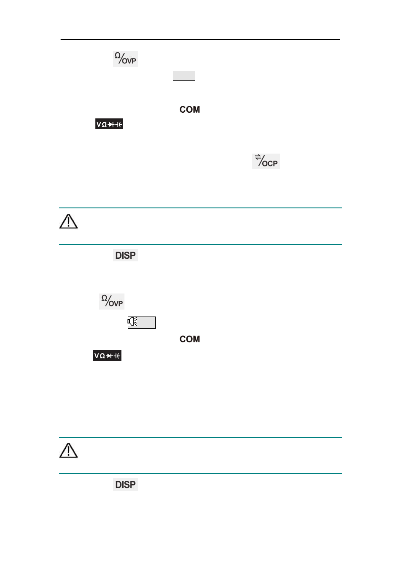
Resistance Measurement
Caution: To avoid possible damage to your multimeter or to the
equipment under test, disconnect the circuit power and discharge
all high-voltage capacitors before measuring resistance.
(1) Press the button on the front panel to switch to the multimeter
interface, and the M icon will be displayed at the upper right corner of the
screen.
4
.
Panel Operation
18
(2) Press the button on the front panel. Resistance measurement
mode will be entered when ΩRes is displayed at the upper left corner of
the screen.
(3) Insert the black test pen into input terminal and the red test pen
into input terminal respectively.
(4) Connect the other ends of the red and black test pens to the tested point
respectively, and read the displayed value. Press button to enter
and switch among manual ranges.
On-off Measurement
Caution: To avoid possible damage to your multimeter or to the
equipment under test, disconnect the circuit power and discharge
all high-voltage capacitors before testing for continuity.
(1) Press the button on the front panel to switch to the multimeter
interface, and the M icon will be displayed at the upper right corner of the
screen.
(2) Press button on the front panel. On-off measurement mode will be
entered when Cont is displayed at the upper left corner of the screen.
(3) Insert the black test pen into input terminal and the red test pen
into input terminal respectively.
(4) Measure the resistance of the tested circuit via the other ends of the red
and black test pens. Buzzer will give out a sound continuously, if the
resistance of the circuit under test is less than 50 Ω.
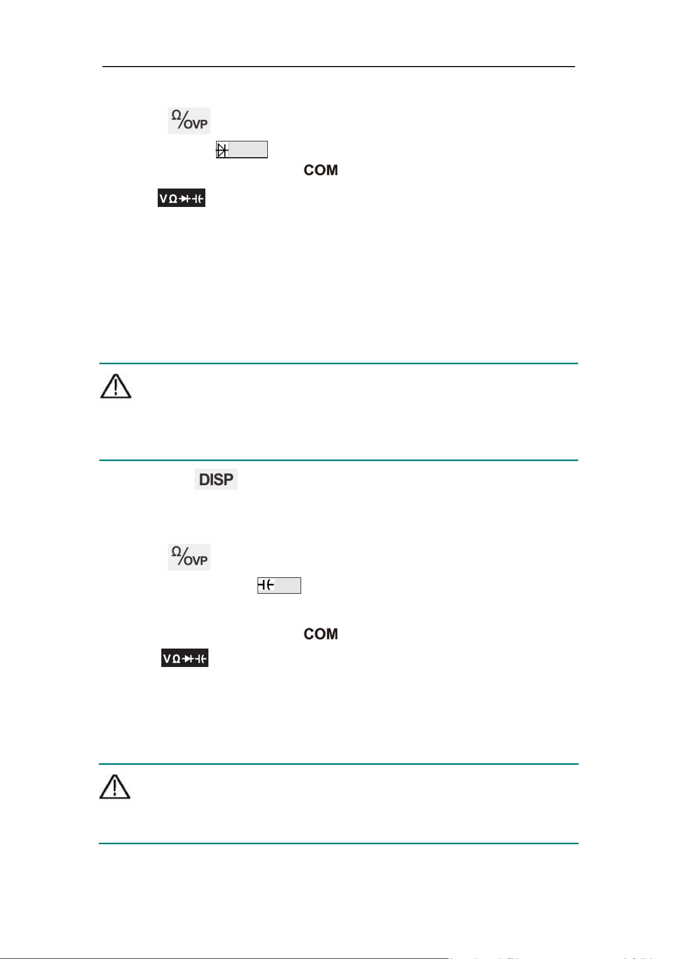
Diode Test
Caution: To avoid possible damage to your multimeter or to the
equipment under test, disconnect the circuit power and discharge
all high-voltage capacitors before testing diodes.
(1) Press the button on the front panel to switch to the multimeter
interface, and the M icon will be displayed at the upper right corner of the
4
.
Panel Operation
19
screen.
(2) Press button on the front panel. Diode measurement mode will be
entered when Diode is displayed at the upper left corner of the screen.
(3) Insert the black test pen into input terminal and the red test pen
into input terminal respectively.
(4) Connect the other end of the red pen to anode of the diode measured and
the other end of the black pen to cathode of the diode.
(5) Read the forward bias value of the diode measured. The display screen
will display “OL”, if the polarity of test pen is connected reversely.
Capacitance Measurement
Caution: To avoid possible damage to the multimeter or to the
equipment under test, disconnect circuit power and discharge all
high-voltage capacitors before measuring capacitance. Use the
DC voltage function to confirm that the capacitor is fully
discharged.
(1) Press the button on the front panel to switch to the multimeter
interface, and the M icon will be displayed at the upper right corner of the
screen.
(2) Press button on the front panel. Capacitance measurement mode
will be entered when Cap is displayed at the upper left corner of the
screen.
(3) Insert the black test pen into input terminal and the red test pen
into input terminal respectively.
(4) Measure the capacitance value via the other ends of the red and black test
pens and read the displayed value.
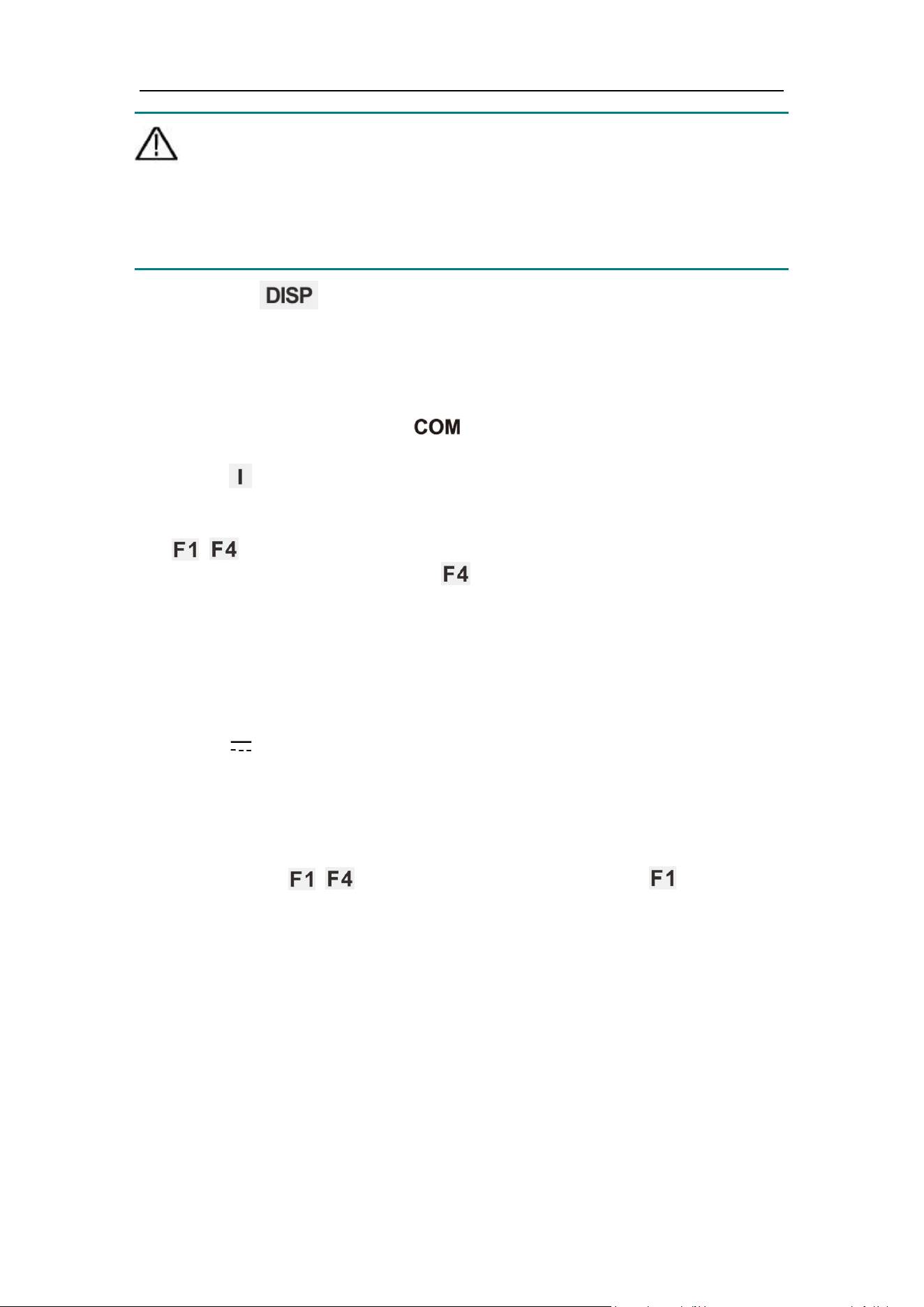
DC or AC Current Measurement
Warning: Never attempt an in-circuit current measurement where the
open-circuit potential to earth is greater than 250 V. Doing so will
cause damage to the multimeter and possible electric shock or
personal injury.
4
.
Panel Operation
20
Caution: To avoid possible damage to the multimeter or to the
equipment under test, check the multimeter’s fuse before
measuring current. Use the proper terminals, function, and range
for your measurement. Never place the test leads in parallel with
any circuit or component when the leads are plugged into the
current terminals.
(1) Press the button on the front panel to switch to the multimeter
interface, and the M icon will be displayed at the upper right corner of the
screen.
(2) Disable the power supply of the circuit measured and discharge all
high-voltage capacitors on the circuit measured.
(3) Insert the black test pen into input terminal and the red test pen
into A input terminal respectively.
(4) Press button on the front panel to enter DC voltage measurement
mode.
(5) Select gear according to the measured range, press any button of
~ on the front panel, and the multimeter sub-menu will be displayed
at bottom of the screen. Press button and select the mA or A gear
required for current measurement.
(6) Disconnect the circuit to be tested. Connect a black pen to one end of the
circuit disconnected (with a lower voltage) and a red pen to the other end
of the circuit (with a higher voltage). If connection is made reversely, the
reading will be negative, but the multimeter will not be damaged.
(7) Select DC or AC measurement mode (DC measurement mode by default).
When DCI is displayed at the upper left corner of the screen, press the
I button to switch to AC voltage measurement mode, and
~
ACI will be
displayed on the screen.
(8) Connect power supply of the circuit and read the displayed value. Press
any button of ~ on the front panel, and then press to enter and
switch the manual range under the current gear. If “OL” appears on the
display screen, it means the input has exceeded the selected range.
(9) Disable the power supply of the circuit measured, discharge all
high-voltage capacitors, remove the test pen and restore the circuit to its
original state.
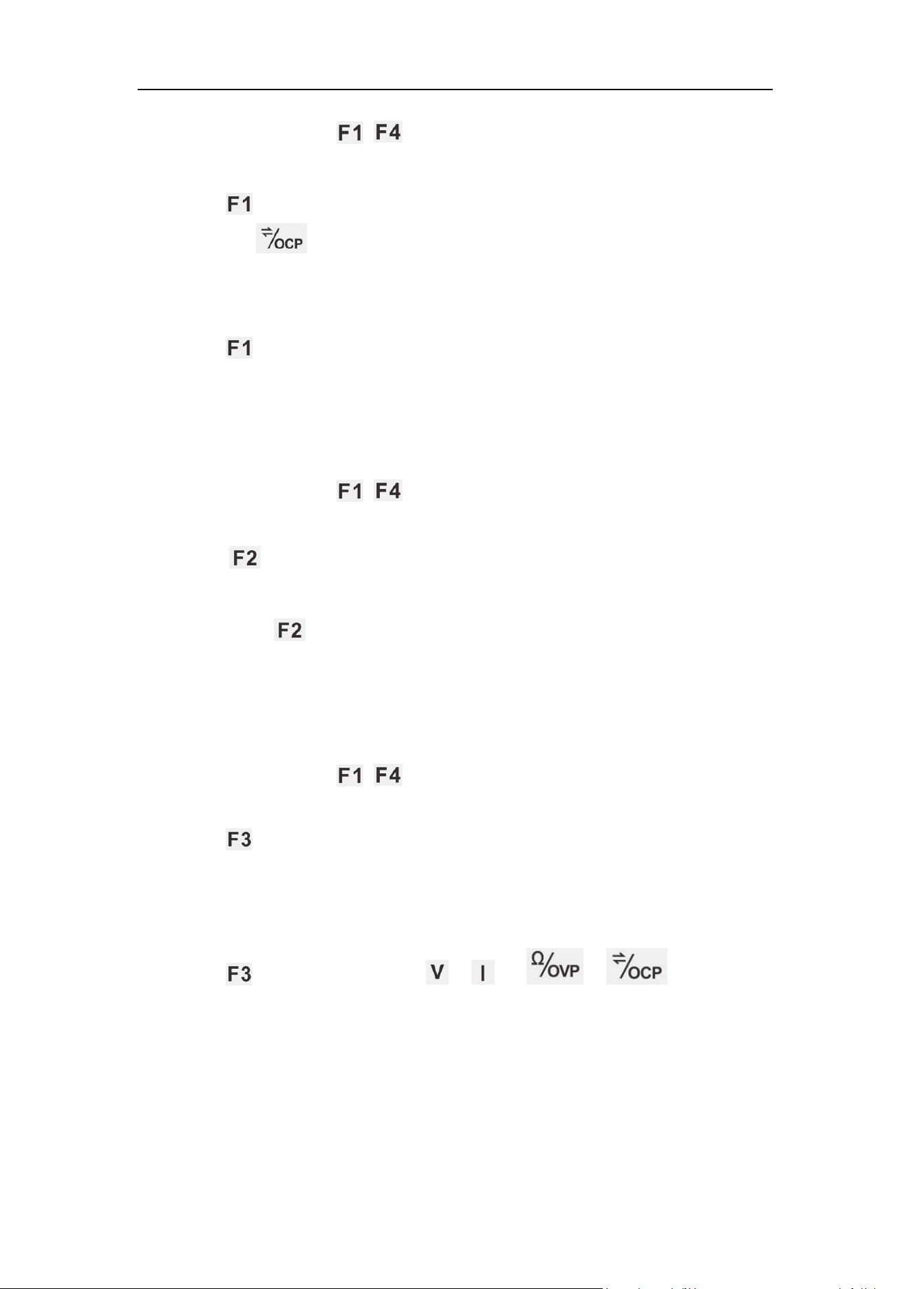
Range Selection
(1) Auto Range is preset during start-up. Auto will be displayed at the top of
the screen under auto range.
4
.
Panel Operation
21
(2) Press any button of ~ on the front panel, and the multimeter
sub-menu will be displayed at bottom of the screen.
(3) Press under auto range to enter manual range mode.
(4) Press the button once under manual range to switch to next higher
range. Upon reaching the highest range, it will be switched to the lowest
one and cycle in turn.
(5) Press button under manual range to enter automatic range mode.
Note: No manual range mode is available for capacitance measurements.
Reading Hold Mode
Under Reading Hold Mode, current reading can remain on the display screen.
(1) Press any button of ~ on the front panel, and the multimeter
sub-menu will be displayed at bottom of the screen.
(2) Press button, and the current reading will be held and the display
screen will show Hold.
(3) Then press button again to exit this mode.
Relative Measurement
Reading under relative measurement is the difference between the stored
reference value and the input signal.
(1) Press any button of ~ on the front panel, and the multimeter
sub-menu will be displayed at bottom of the screen.
(2) Press button to enter the relative value measurement mode,
△
(current reading) will be displayed on the display screen. The measured
value when pressing the button will be stored as the reference value. In
this mode,
△
(current reading)= input value – reference value.
(3) Press again or press the / / / button to exit
this mode.Enter manual range automatically after entering this mode.
(Relative value measurement is allowed only within a certain range, i.e.
only in manual range mode.)
Note: This function is unavailable when measuring AC voltage, AC current,
diodes and on-off.
4
.
Panel Operation
22
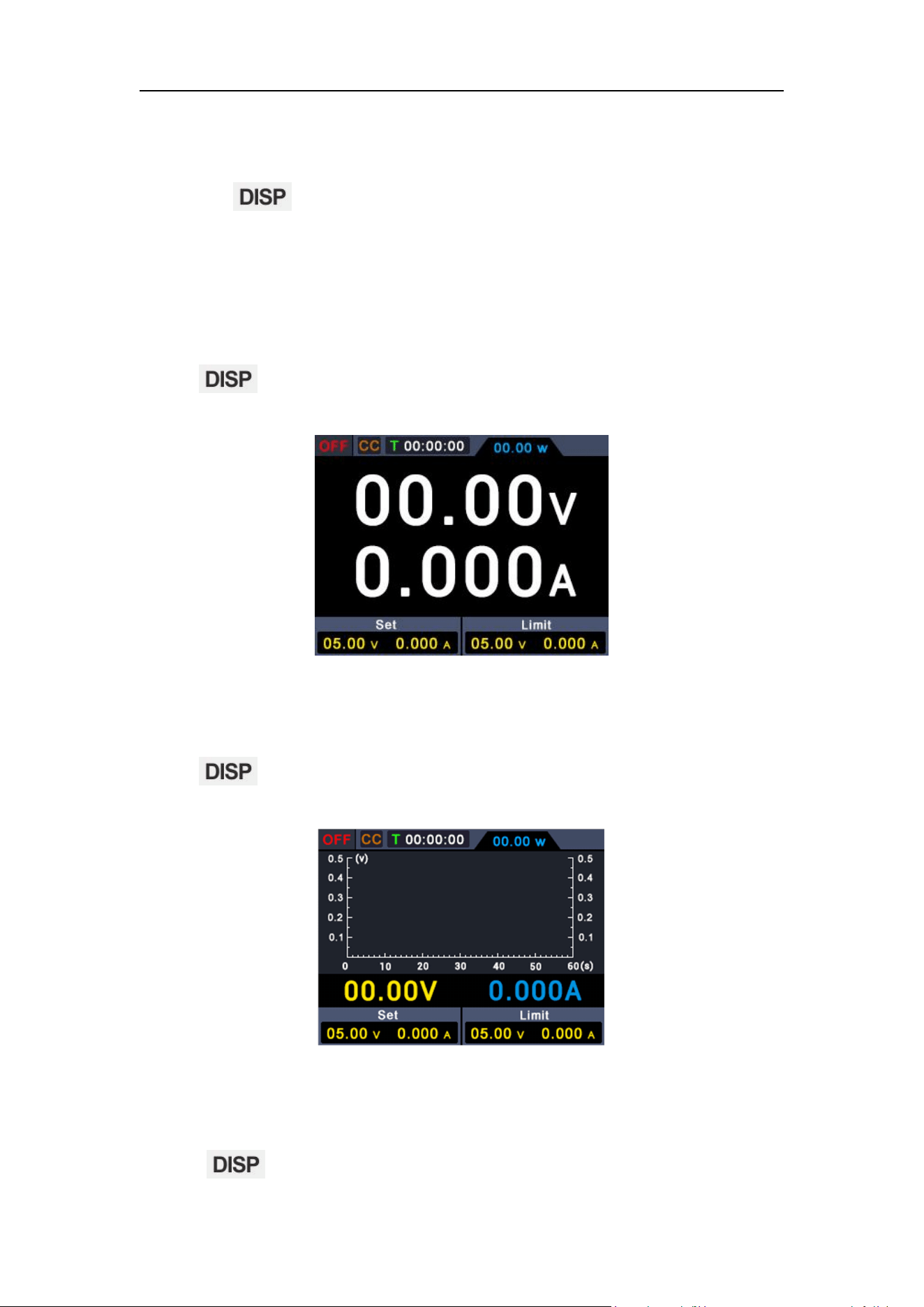
4.9 Display
(
DISP
)
Press the function button to switch the display: Power interface of
digital measurement data, power interface of curve measurement data,
multimeter interface and dual display interface of power and multimeter.
4.9.1 Number
Press function button to select power value reading in the form of
curve.
4.9.2 Curve
Press function button to select power value reading in the form of
curve.
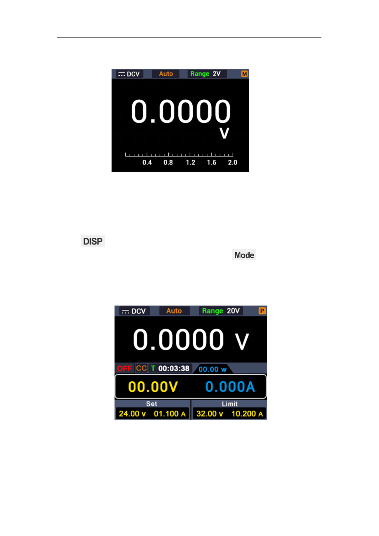
4.9.3 Interface of Multimeter Measurement
Press function button to select the interface of multimeter
4
.
Panel Operation
23
measurement.
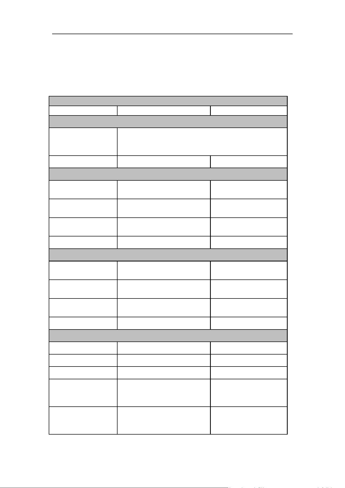
4.9.4 Dual-display Measurement Interface of Power
Supply and Multimeter
Press function button and select dual-display measurement interface
of power supply and multimeter. After pressing the button, it indicates
that the measured value of power supply is editable, if P appears at the upper
right corner of the screen; multimeter is under editable status, if M appears at
the upper right corner of the screen.

5
.
Troubleshooting
24
5. Troubleshooting
1. The instrument is powered on but no Display.
Check if the power is connected properly.
Check if the fuse which is below the AC Power socket is used
appropriately and in good condition (the cover can be pried open with a
straight screwdriver).
Restart the instrument after the steps above.
If the problem still exists, please contact us for our service.
2. The output is abnormal:
Check if the output voltage is set to 0V. If so, set it to other value.
Check if the output current is set to 0A. If so, set it to other value.
When in programmable output status, check if there is any
voltage/current value is set to 0. If so, set it to other value.
If the problem still exists, please contact us for our service.
6
.
Technical Specification
25
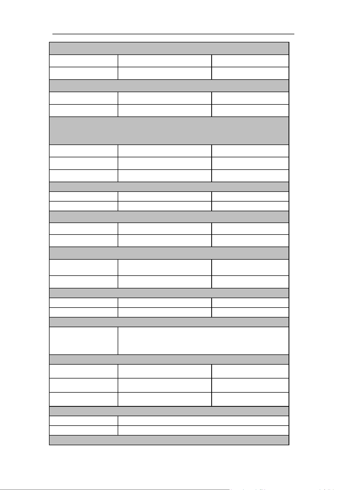
6. Technical Specification
The instrument must be operated continuously for more than 30 minutes at the
specified operating temperature to achieve the following specifications
Specifications
DC310Pro
DC605Pro
Input Characteristics
Supply Voltage
110Vac±15% or 220Vac±15%, please supply power
according to the mark on the left of the power input
socket on the rear panel of the instrument
Input Frequency
45~65Hz
45~65Hz
Input Parameter 1
(
110Vac±15%
)
Input Voltage
Range
93~127Vac
93~127Vac
Full Load Input
Current
≤5.6A
≤5.6A
No-Load Input
Current
≤300mA
≤300mA
Input Fuse
250V,F10A
250V,F10A
Input Parameter 2(220Vac±15%)
Input Voltage
Range
187~253Vac
187~253Vac
Full Load Input
Current
≤2.8A
≤2.8A
No-Load Input
Current
≤150mA
≤150mA
Input Fuse
250V,F5A
250V,F5A
Rated Output
Voltage
0~30V
0~60V
Current
0~10A
0~5A
Power
300W
300W
Efficiency
(110Vac, rated
load)
80%
80%
Efficiency
(220Vac, rated
load)
85%
85%
6
.
Technical Specification
26
Regulation(CV)
Load
≤30mV
≤30mV
Line
≤20mV
≤20mV
Regulation(CC)
Load
≤30mA
≤30mA
Line
≤20mA
≤20mA
Ripple & Noise (Noise bandwidth 20MHz, ripple bandwidth 1MHz,
connect 10uF electrolytic capacitor in parallel with 0.1uF ceramic
capacitor to the output terminal for testing)
Voltage (Vp-p)
≤30mV
≤30mV
Voltage (rms)
≤3mV
≤3mV
Current (Ap-p)
≤30mA
≤30mA
Setting Resolution
Voltage
10mV
10mV
Current
1mA
1mA
Readback Resolution
Voltage
10mV
10mV
Current
1mA
1mA
Setting Accuracy
Voltage
≤0.1%±20mV
≤0.1%±20mV
Current
≤0.1%±10mA
≤0.1%±10mA
Readback Accuracy
Voltage
≤0.1%±20mV
≤0.1%±20mV
Current
≤0.1%±10mA
≤0.1%±10mA
Response time
Transient recovery
time(50% ~
100%rated load)
≤1ms
Protective function
OVP
0~61V
0~31V
OCP
0~10.1A
0~5.1A
OTP
85℃
85℃
Temperature coefficient of output
Voltage
100ppm/℃
Current
200ppm/℃
Temperature coefficient of readback value
6
.
Technical Specification
27
Voltage
100ppm/℃
Current
200ppm/℃
Multimeter parameters
Digital display
4½ bits(Maximum reading 20000)
Measurement
Voltage、Current、Resistance、Capacitance、Diode、
On and off
Input impedance
≥10 MΩ
Diode
0~2V
Range
Accuracy
Voltage(DC)
200.00mV
±(0.3%+10dig)
2.0000V/20.000V/200.00V
±(0.3%+5dig)
1000.0V
Voltage(AC)
200.00mV/2.0000V
/20.000V/200.00V
±(0.8%+10dig)
750V
±( 1.0%+10dig)
Current(DC)
200.00mA
±(0.8%+10dig)
10.000A
±(2.5%+10dig)
Current(AC)
200.00mA
±( 1.0%+10dig)
10.000A
±(2.8%+10dig)
Resistance
200.00Ω/2.0000kΩ/20.000kΩ/
200.00kΩ/2.0000MΩ
±(0.8%+10dig)
20.000MΩ
±( 1.0%+3dig)
100.00MΩ
±(5.0%+10dig)
Capacitance[1]
(
F
)
20.000nF/200.00nF/2.0000uF/
20.000uF/200.00uF/2.0000mF
±(3.0%+10dig)
Frequency
response(Hz)
(40 - 1000)Hz
Display
Display Type
2.8inches color LCD
Resolution
480 × 320 pixels
Color
65536 color,TFT
Environment
Temperature
Working Temperature:0℃~40℃
Storage Temperature:-20℃~60℃
Relative Humidity
≤90%RH; no condensation
Height
2,000 meters
Cooling
Fan cooling, temperature intelligent speed control
Other
Communication Port
USB communication, compatible with SCPI
communication protocol
USB Charging Port
5V/1A USB charging
Dimension
82mm(Width)× 142mm(Height)×226mm(Length)

6
.
Technical Specification
28
Weight
Approx. 1.5 kg
[1] For AC voltage/current and capacitance measurement, accuracy is
guaranteed from 5% to 100% range.
7
.
Appendix
29
7. Appendix
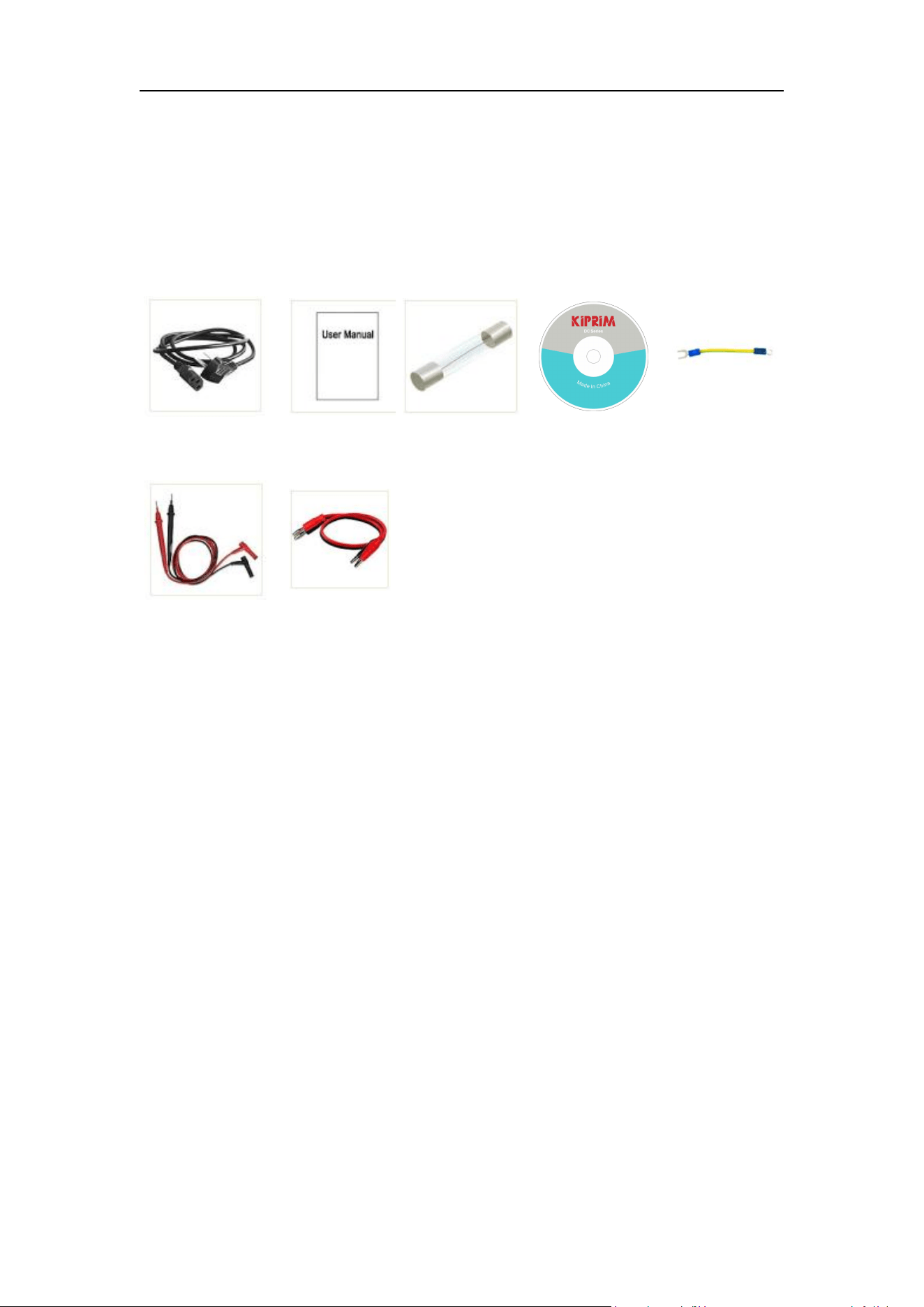
7.1 Appendix A:Accessories
(The accessories subject to final delivery. )
standard:
Power Cord
User Manual
Fuse
CD
Grounding
Leads
Multimeter Leads
Banana plug
to crocodile
clip test
leads
7.2 Appendix B: General Care and Cleaning
General Care
Do not store or leave the instrument where the liquid crystal display could be
exposed to direct sunlight for long periods of time.
Caution: To avoid any damage to the instrument, do not exposed it to any
sprays, liquids, or solvents.
Cleaning
Inspect the instrument as often as operating conditions require. To clean the
instrument exterior, perform the following steps:
Wipe the dust from the instrument surface with a soft cloth. Take care not to
scratch the transparent LCD protection screen when cleaning.

7
.
Appendix
30
Disconnect power before cleaning your instrument. Clean the instrument
with a damp soft cloth (not dripping with water). It is recommended to
clean with soft detergent or fresh water. To avoid damage to the
instrument, do not use any corrosive chemical cleaning agents.
Warning: Before re applying power, ensure that the instrument is
completely dry, avoiding any electric shock or electrical short
circuit resulting from moisture.