NOTE:
Product may vary slightly from the item pictured due to model upgrades. This manual may be subject to updates or changes.
Up to date manuals are available through our website at www.lifespanfitness.com.au
Read all instructions carefully before using this product.
Retain this owner’s manual for future reference.
IMPORTANT
All nuts and bolts are to be checked and tightened on a regular basis. This includes pedals and
other moving parts. Failure to do so may cause damage to your threads and void your warranty.
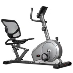
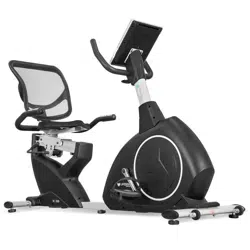
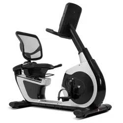
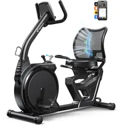
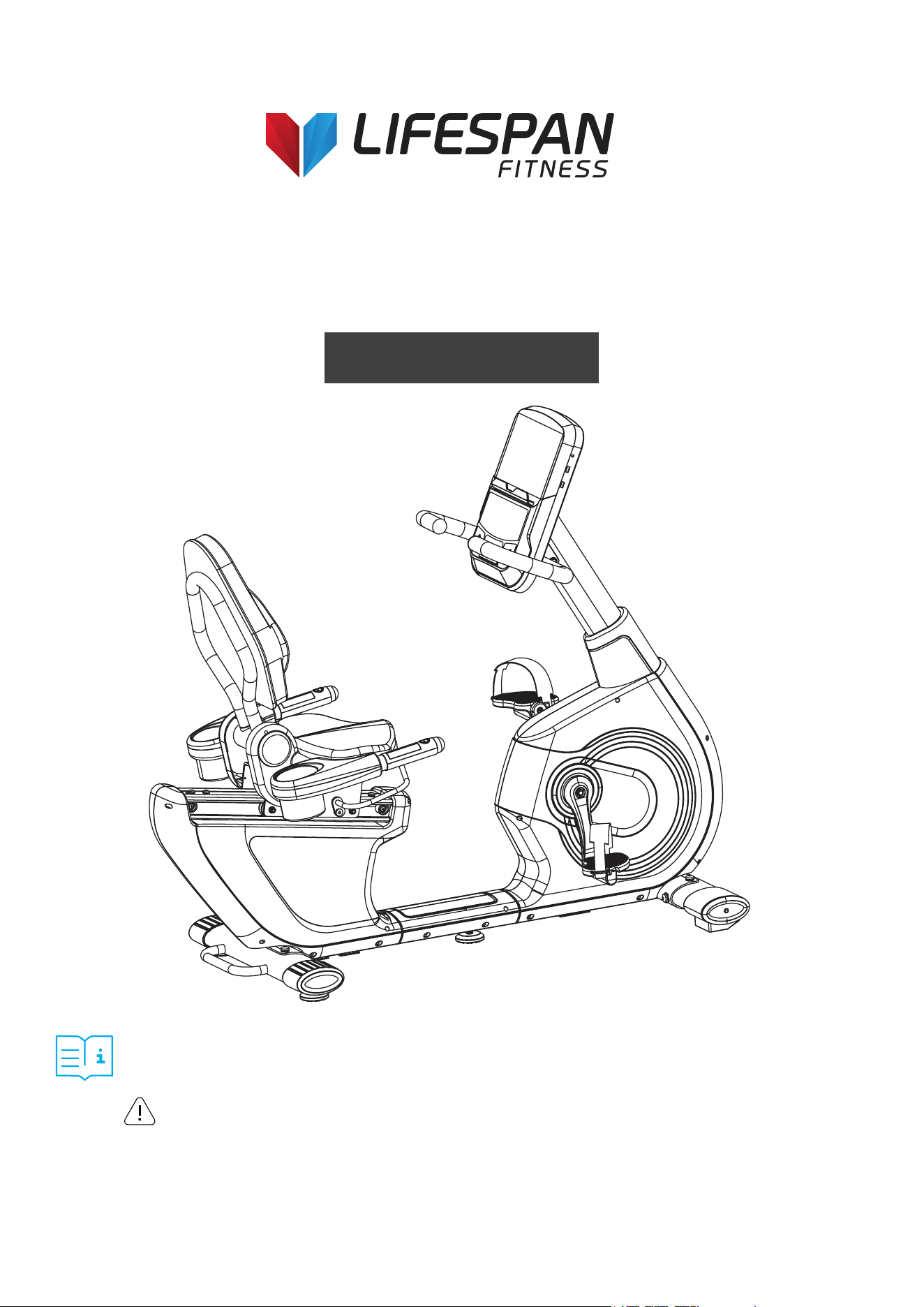
RBX-100
Commercial Recumbent Bike
USER MANUAL

2
TABLE OF
CONTENTS
I. Important Safety Instructions . . . . . . . . . . . . . . . . . . . . . . . . . . . . . . . 03
II. Care Instructions . . . . . . . . . . . . . . . . . . . . . . . . . . . . . . . . . . . . . . . . . . . . . 04
III. Exploded Diagram . . . . . . . . . . . . . . . . . . . . . . . . . . . . . . . . . . . . . . . . . . . . 05
IV. Parts List . . . . . . . . . . . . . . . . . . . . . . . . . . . . . . . . . . . . . . . . . . . . . . . . . . . . . . 06
V . Assembly Instructions . . . . . . . . . . . . . . . . . . . . . . . . . . . . . . . . . . . . . . . 07
VI. Computer Operation . . . . . . . . . . . . . . . . . . . . . . . . . . . . . . . . . . . . . . . . 14
VII. Exercise Guide. . . . . . . . . . . . . . . . . . . . . . . . . . . . . . . . . . . . . . . . . . . . . . . . 22
VIII. Warranty . . . . . . . . . . . . . . . . . . . . . . . . . . . . . . . . . . . . . . . . . . . . . . . . . . . . . . 23
| TABLE OF CONTENTS

3
I. IMPORTANT SAFETY
INSTRUCTIONS
WARNING: Read all instructions before using this machine.
Note the following precaution before assembling and operating the machine.
• Assemble the machine exactly as the descriptions in the instruction manual.
• Check all the bolts, nuts, and other connections before using the machine for the first time to
ensure the machine is in the safe condition.
• Set up the machine in a dry level place and keep it away from moisture and water.
• Place a suitable base (e.g., rubber mat, wooden board etc.) beneath the machine in the
area of assembly to avoid dirt.
• Before beginning the training, remove all objects within a radius of 2 meters from the machine.
• Do not use aggressive cleaning articles to clean the machine. Only use the supplied tools or suitable
tools of your own to assemble the machine or repair any parts of machine. Remove drops of sweat
from the machine immediately after finishing training.
• Your health can be affected by incorrect or excessive training. Consult a doctor before beginning the
training program. He can define the maximum setting (Pulse. Watts. Duration of training etc) to which
you may train yourself and can get precise information during training. This machine is not suitable
for therapeutic purpose.
• Only do training on the machine when it is in correct working way. Use only original spare parts
for any necessary repairs.
• This machine can be used for only one person’s training at a time.
• Wear training clothes and shoes that are suitable for fitness training with the machine. Your
training shoes should be appropriate for the trainer.
• If you have a feeling of dizziness, sickness, or other abnormal symptoms, please stop training
and consult a doctor immediately.
• People such as children and handicapped persons should only use the machine in the presence of
another person who can give aid and advice.
• The power of the machine increases with increasing the speed, and the reverse. The machine is
equipped with adjustable knob that can adjust the resistance.
• Maximum user’s weight is 150kg.
IMPORTANT SAFETY INSTRUCTIONS |

4
II. CARE INSTRUCTIONS
• All nuts and bolts are to be checked and tightened on a regular basis. This includes pedals and other
moving parts. Failure to do so may cause damage to your thread and void your warranty.
• Lubricate moving joints with grease after periods of usage.
• Be careful not to damage plastic or metal parts of the machine with heavy or sharp objects.
• The machine can be kept clean by wiping it down using dry cloth.
| CARE INSTRUCTIONS
5 EXPLODED DIAGRAM |
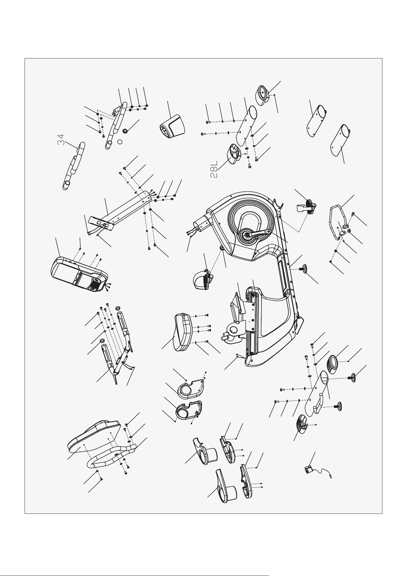
III. EXPLODED DIAGRAM
38
20
12
10
17
12
46
35
13
20
47
12
13
32R
32L
31L
31R
40
11
15
19
9
18
15
27
40
33
11
27
41
40
30L
30R
36
20
5
12
2
12
12
16
20
3
12 16
20
12
12
43
37L
21L
22
21R
33
45
20
14
23
7
6
24
42
42
1
37R
11
15
18
40
28R
8
19
15
11
25
36
4
16
17
20
20
16
16
48
44
39
16
29

6
IV. PARTS LIST
Part No. Description Qty
1
Main frame 1
2
Handlebar post
1
3
Handlebar
1
4
Seat slider
1
5
Handlebar connection
1
6
Adjustable handlebar
1
7
Adjustable connector
1
8
Front stabilizer
1
9
Rear stabilizer
1
10
Back bracket
1
11
Inner hex screw M10x25
8
12
Cross pan screw M14*10
23
13
Cross pan screw M14*10
6
14
Screw M8*10
2
15
Spring washer D10
8
16
Spring washer D8
14
17
Arc washer D8.2*Ф20*2
4
18
Arc washer D10*Ф25*2
4
19
Flat washer D10*D20*2
4
20
Flat washer D8*D19*1.5
20
21L/R
Arc crank
1pr
22
Aluminum railway
1
23
Spacer
1
24
Bolts
1
Part No. Description Qty
25
Handlebar post cover 1
27
Bottom tube end cap
2
28L/R
Front left &right end cap
1pr
29
Cross pan screw M4*10
4
30L/R
Left & right bottle bracket
1pr
31L/R
Left & right bottle base
1pr
32L/R
Left & right seat cover
1pr
33
Adjustable pad
3
34
Foam grip
2
35
Seat
1
36
Arc shaped round end cap
4
37L/R
L&R pedal
1pr
38
Back pad
1
39
Console
1
40
Cross pan screw ST4.2*18
10
41
Adaptor
1
42
Tube for package
2
43
Sensor wire
1
44
Sensor extension wire
1
45
Nylon nut M8
1
46
Handle pulse
2
47
Extension wire 1
2
48
Extension wire 2
2
| PARTS LIST
7ASSEMBLY INSTRUCTIONS |
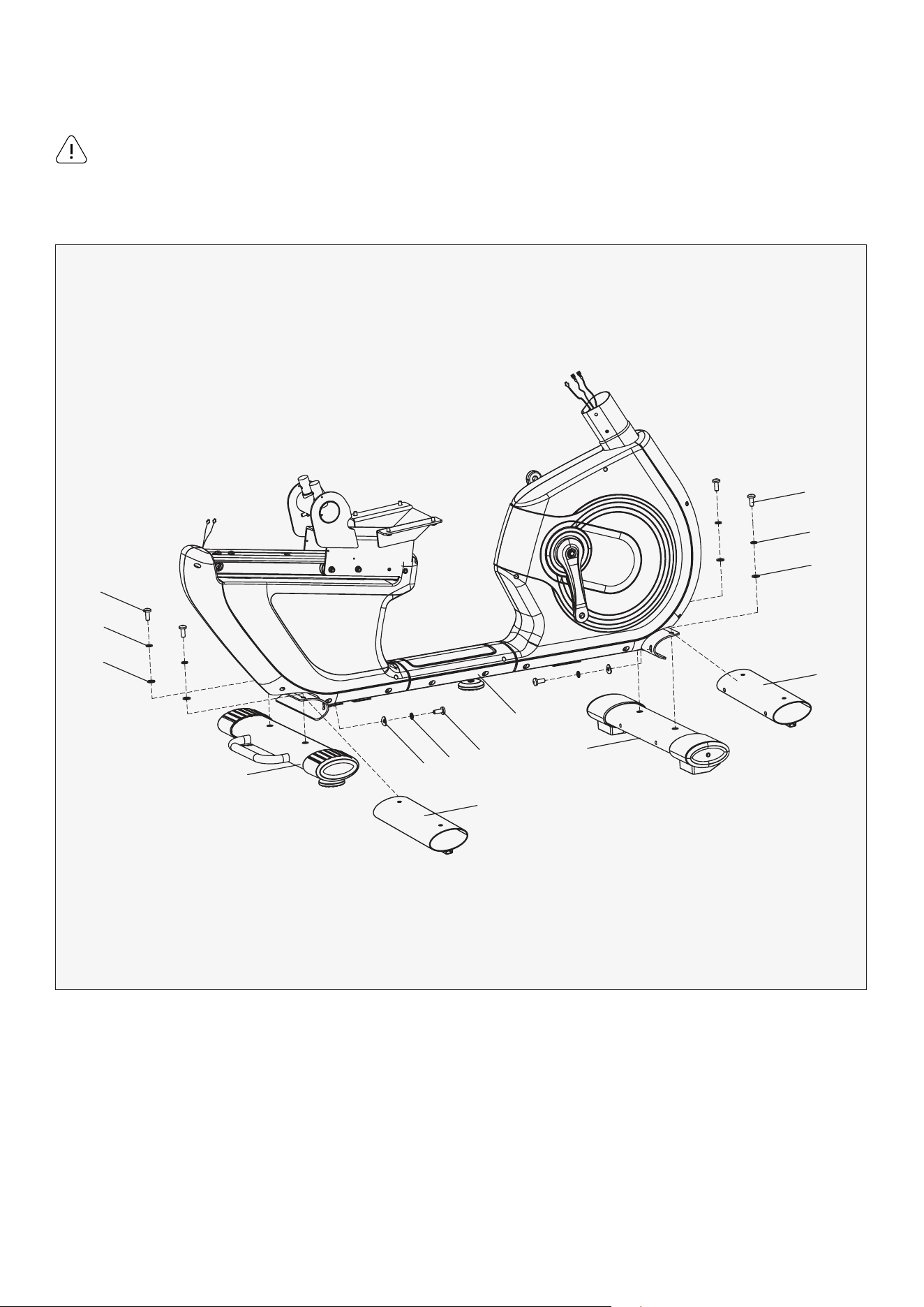
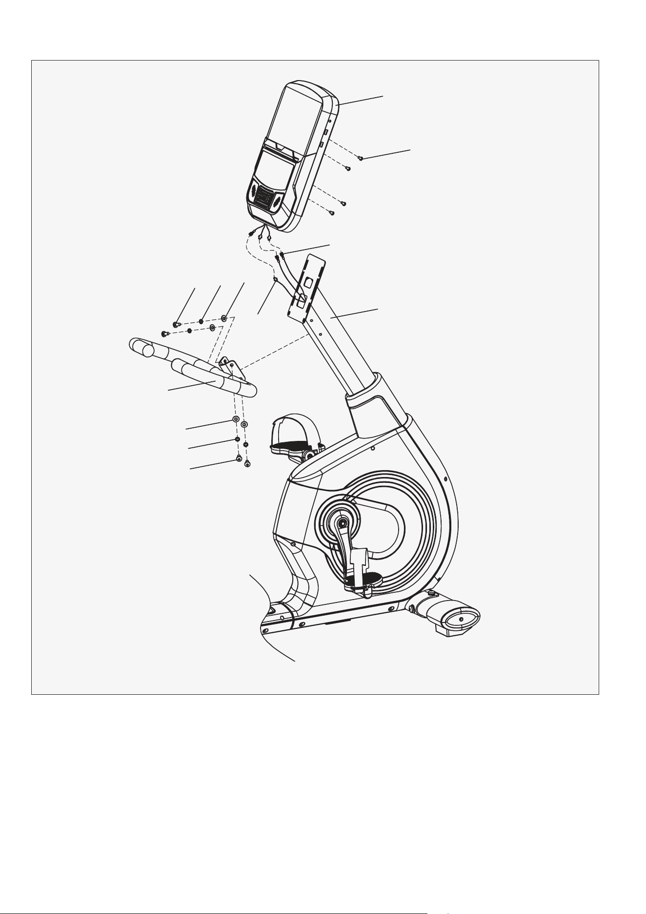
V. ASSEMBLY INSTRUCTIONS
1. First, take off the Tube for package (42), inner hex screw (11), spring washer (15) and flat washer (19)
from main frame (1).
2. Fix the front stabilizer (8) and the rear stabilizer (9) to the main frame (1) with inner hex screw (11)
spring washer (15), flat washer (19) and arc washer (18).
Please follow these assembly instructions step by step to assemble this bike.
Some of the hardware is pre-installed on the parts.
STEP 1
11
15
19
42
8
1
42
9
19
15
11
11
18
15
Attention:
8 | ASSEMBLY INSTRUCTIONS
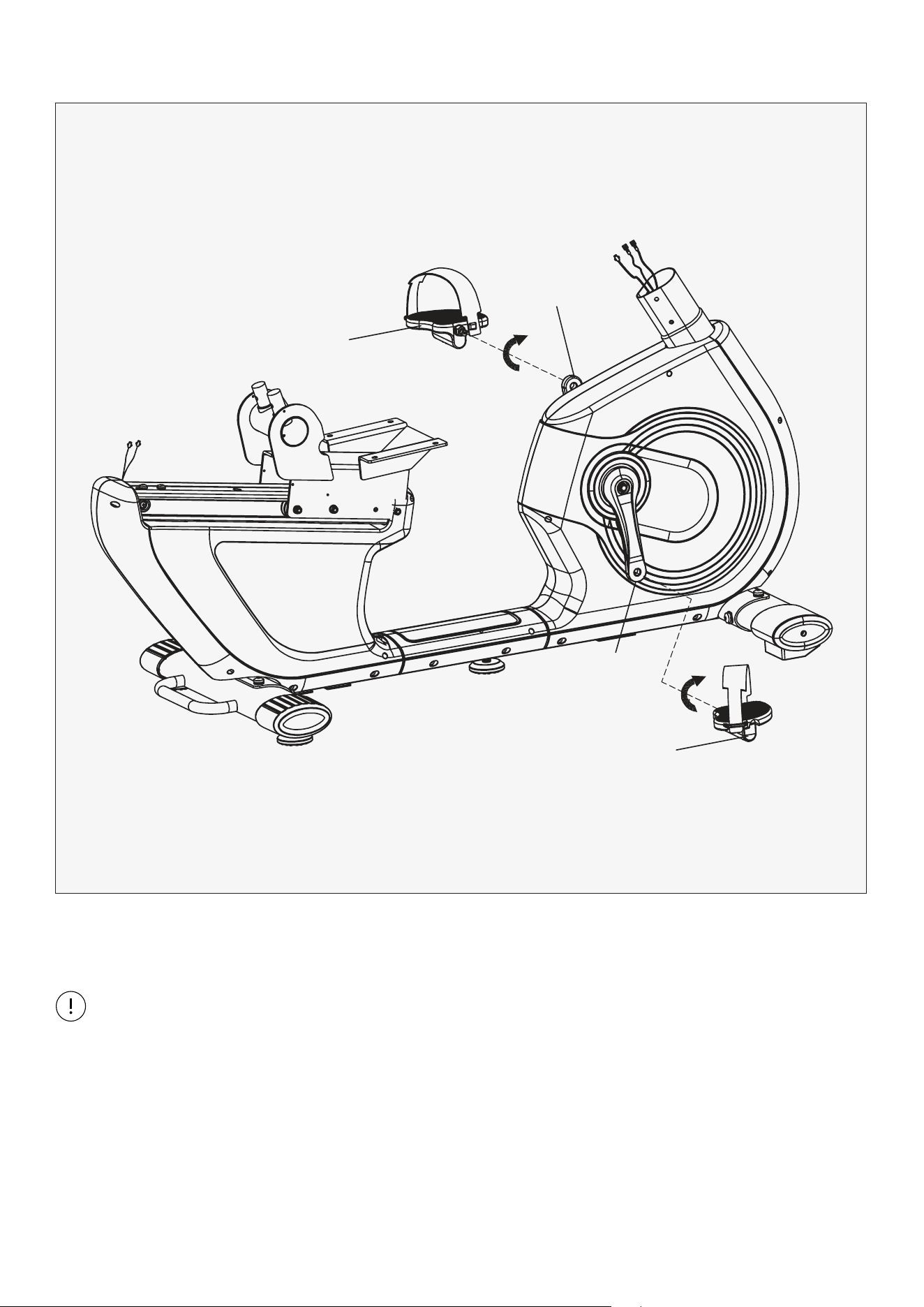
1. Install the Pedal (37L/R) to the Crank (21L/R) respectively.
STEP 2
Note: Secure the Left Pedal (37L) Anticlockwise and the Right Pedal (37R) Clockwise as shown.
Please make sure that the Pedal (37L/R) have been locked tightly before exercise.
37L
37R
21L
21R
9ASSEMBLY INSTRUCTIONS |
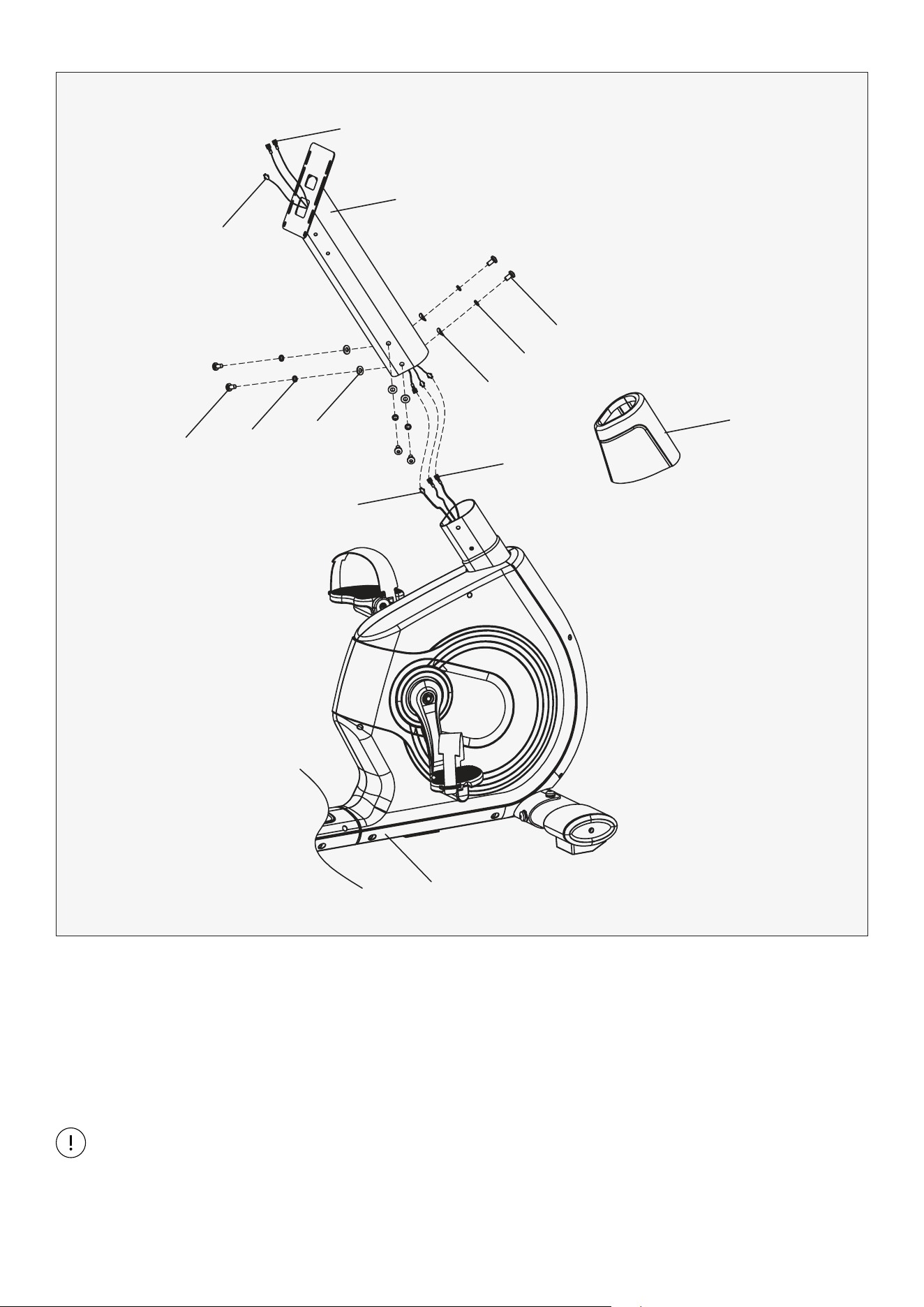
1. First, sleeve the handlebar post cover (25) into handlebar post (2). Then connect extension wire 1 (47)
and extension wire 2 (48), sensor extension wire (44) and sensor wire (43).
2. Lock handlebar post (2) to the post of main frame (1) with inner hex screw (12), spring washer (16),
arc washer (17) and flat washer (20).
STEP 3
Note: When you insert handlebar post (2), be careful not to clamp down on any of the wires.
Finally, insert the handlebar post cover (25).
48
44
2
12
16
17
47
25
20
43
16
12
1
10 | ASSEMBLY INSTRUCTIONS
STEP 4
1. Fix handlebar (3) to the handlebar post (2) with inner hex screw (12), spring washer (16) and flat
washer (20).
2. Connect extension wire 2 (48), sensor extension wire (44) and the wire of console (39). Then lock
the console (39) to handlebar post (2) with 4x cross pan screw (29). The screws are pre-installed
on the back of the display, remove it and reinstall to the post.
39
29
48
12
3
20
16
12
20
44
16
2
11ASSEMBLY INSTRUCTIONS |
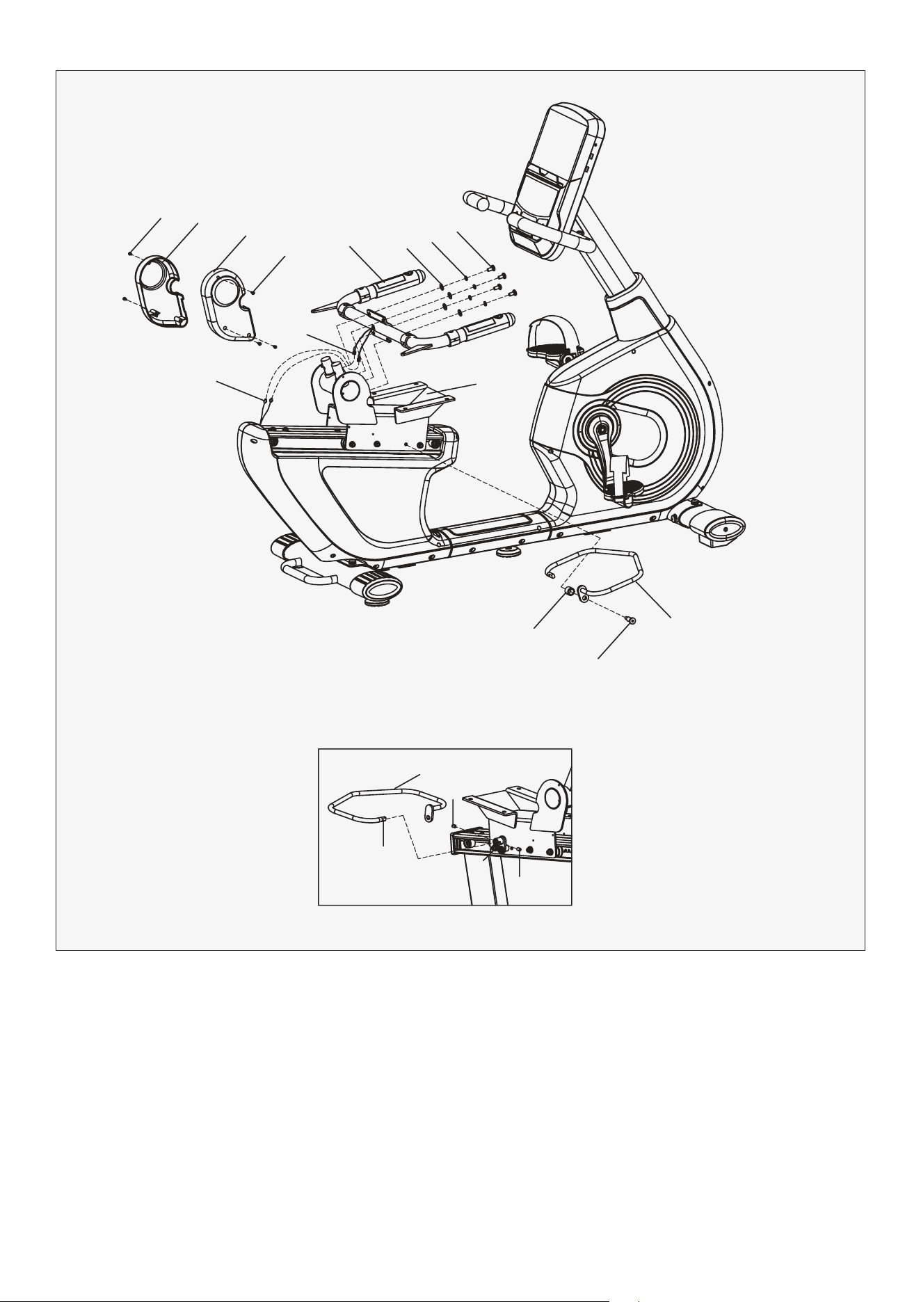
1. Lock left & right seat cover (32L/R) to the seat slider (4) with cross pan screw (13).
2. First, connect handle pulse (46) and extension wire 1 (47). Then fix handlebar connection (5) to
seat slider (4) with inner hex screw (12), spring washer (16) and flat washer (20).
3. Screw off the screw (14) from the adjustable connector (7), then insert the C end of adjustable
handlebar (6) into adjustable connector (7), finally fix it with screw (14).
4. Lock adjustable handlebar (6) to seat slider (4) tightly with spacer (23) and bolt (24).
STEP 5
13
13
5
20
16
12
4
23
24
6
A
C
6
14
14
7
32L
32R
47
12 | ASSEMBLY INSTRUCTIONS
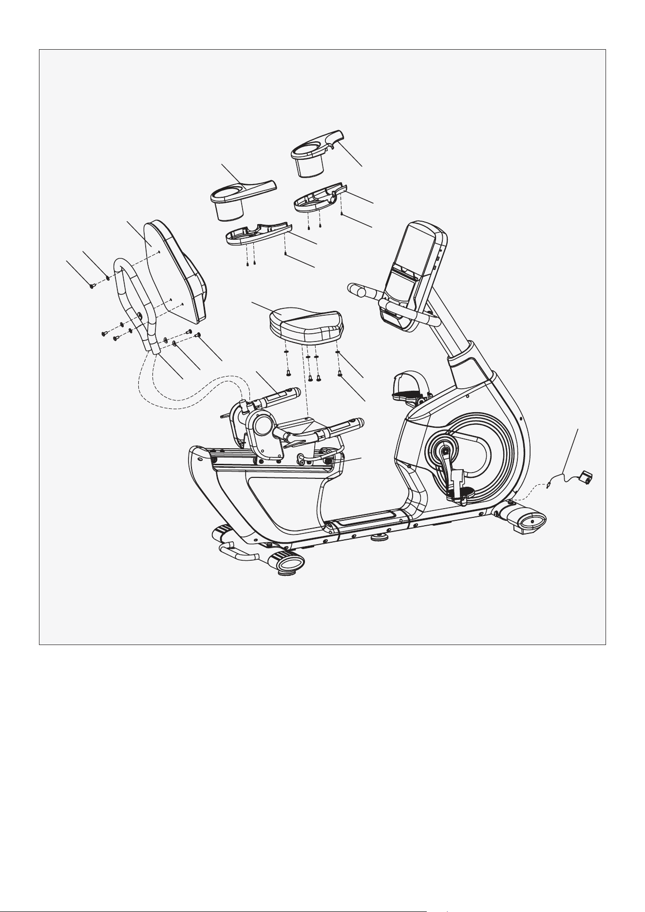
1. Firstly, lock the seat (35) to seat slider (4) tightly with inner hex screw (12) and flat washer (20).
2. Insert back bracket (10) into the connection axle of seat slider (4). Then, lock the back bracket (10)
tightly with inner hex screw (12) and arc washer (17).
3. Lock the back pad (38) to back bracket (10) with inner hex screw (12) and flat washer (20).
4. Lock the Left & right bottle bracket (30L/R) and left & right bottle base (31L/R) to the handlebar
connection (5) with cross pan screw (40) respectively. The screws are pre-installed on the holder.
5. Connect power adapter (41) to the machine located at the front wheel on the bottom.
STEP 6
12
20
38
35
40
40
31R
31L
30L
30R
5
4
20
12
12
17
10
41
13HOW TO GUIDE |
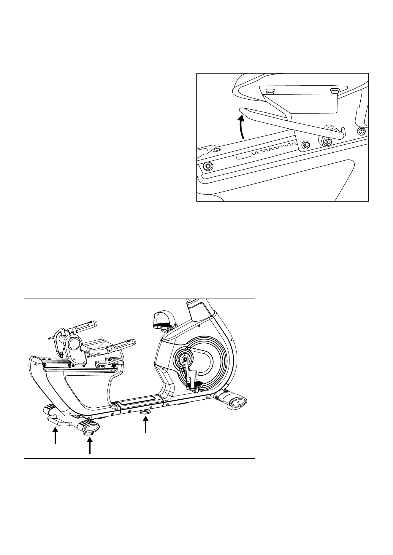
Adjusting Seat Horizontal
Position
Floor Levelers
Under the seat is an Adjustable handlebar (6).
While you are sitting on the equipment with
your feet on the pedals, unlock the seat by
pulling the handle up then move your seat
forward or backward to your desired position,
and release the handle to lock. Check your
seat is clicked into place by moving the
seat forward and backward.
If your ground is uneven, there is three Adjusting pad (part 33) at the back stabilizer feet and
underneath the middle of frame. Turn these pads clockwise or anti-clockwise until the sit firmly
on the ground and the equipment no longer shakes.

14 | COMPUTER OPERATION
VI. COMPUTER OPERATION
DISPLAY FUNCTION
KEY FUNCTION
ITEM DESCRIPTION
TIME
Count up - No preset target, Time will count up from 00:00 to maximum 99:59 with
each increment is 1 minute.
Count down - If training with preset Time, Time will count down from preset to 00:00.
Each preset increment or decrement is 1 minute between 00:00 to 99:00.
SPEED Displays current training speed. Maximum speed is 99.9 KM/H or ML/H.
RPM Displays the Rotation Per Minute. Display range 0~15~999.
DISTANCE
Accumulates total distance from 0.00 up to 99.99 KM or ML. The user may preset target
distance data by using UP/DOWN button.
Each preset increment or decrement is 0.1KM or ML between 0.00 to 99.90.
CALORIES
Accumulates calories consumption during training from 0 to maximum 9999 calories.
(This data is a rough guide for comparison of different exercise sessions which can not
be used in medical treatment.)
PULSE
User may set up target pulse from 0 - 30 to 230; and computer buzzer will beep when
actual heart rate is over the target value during workout.
WATTS Display current workout watts. Display range 0~999.
MANUAL Manual mode workout.
PROGRAM 12 PROGRAM selection.
USER PROGRAM User creates resistance level profile.
H.R.C. Target HR training mode.
WATT PROGRAM WATT constant training mode.
ITEM DESCRIPTION
Up (Encoder)
Increase resistance level. Setting selection.
Down (Encoder) Decrease resistance level. Setting selection.
Mode/Enter Confirm setting or selection.
Reset
Press and hold for 2 seconds, computer will reboot and start from user setting.
Reverse to main menu during preset workout value or stop mode.
Start/Stop
Start or Stop workout.
Recovery
Test heart rate recovery status.
Body fat In stop mode, press it for body fat measurement
15COMPUTER OPERATION |
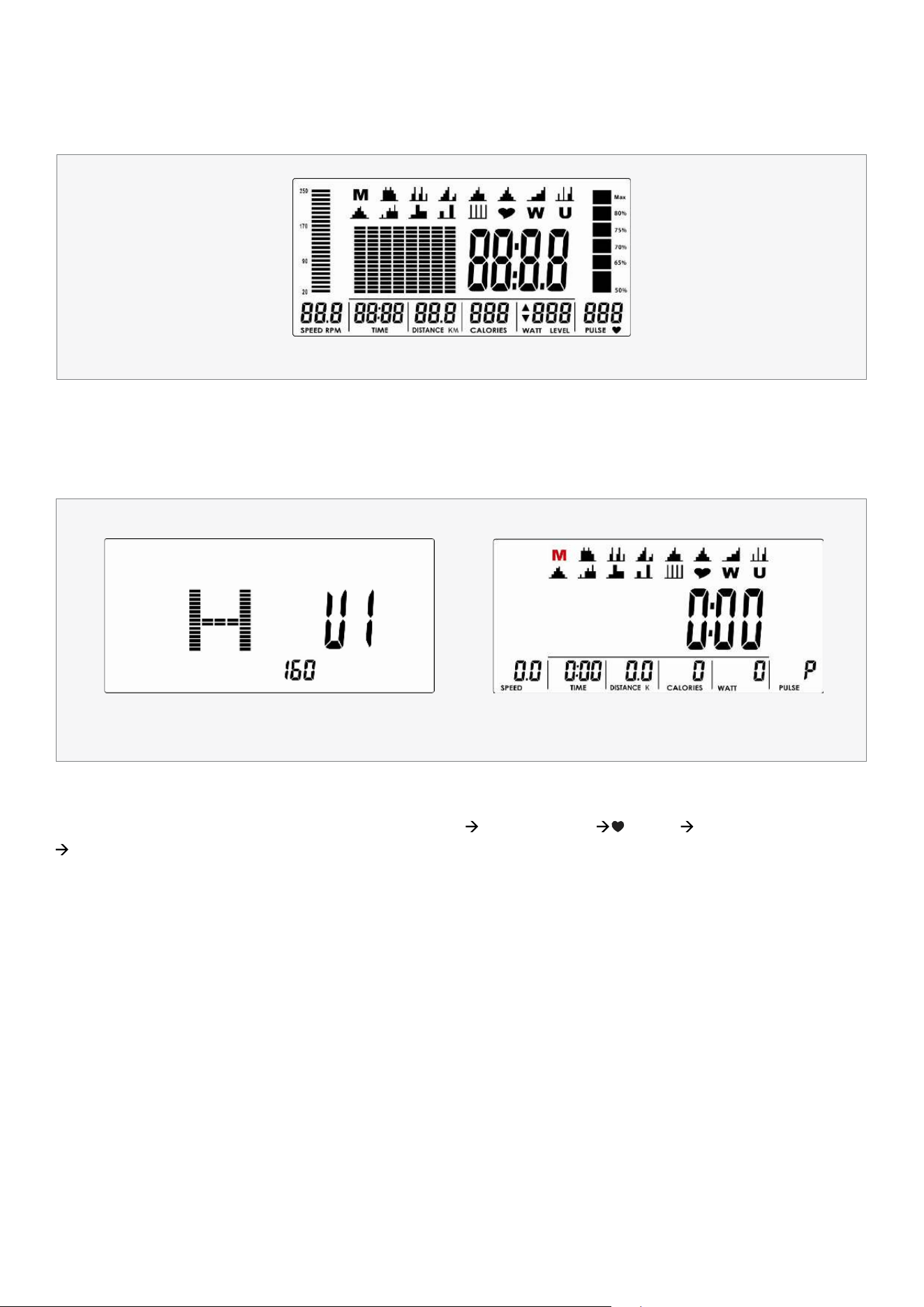
POWER ON
Plug in power supply, computer will power on and display all segments on LCD for 2 seconds (Drawing 1).
Then enter into User data setting. Use UP or DOWN (Encoder) to select U1~U4, then set SEX, AGE,
HEIGHT (Drawing 2), WEIGHT and confirm by pressing MODE/ENTER key. When you have finished
entering user data the console will go back to main menu (Drawing 3).
OPERATION PROCEDURE
Drawing 1
Drawing 2 Drawing 3
WORKOUT SELECTION
Use UP or DOWN (Encoder) to select workout : M(Manual) P(Program 1-12) (H.R.C) W(WATTS)
U(User), press MODE / ENTER to select setting.
16 | COMPUTER OPERATION
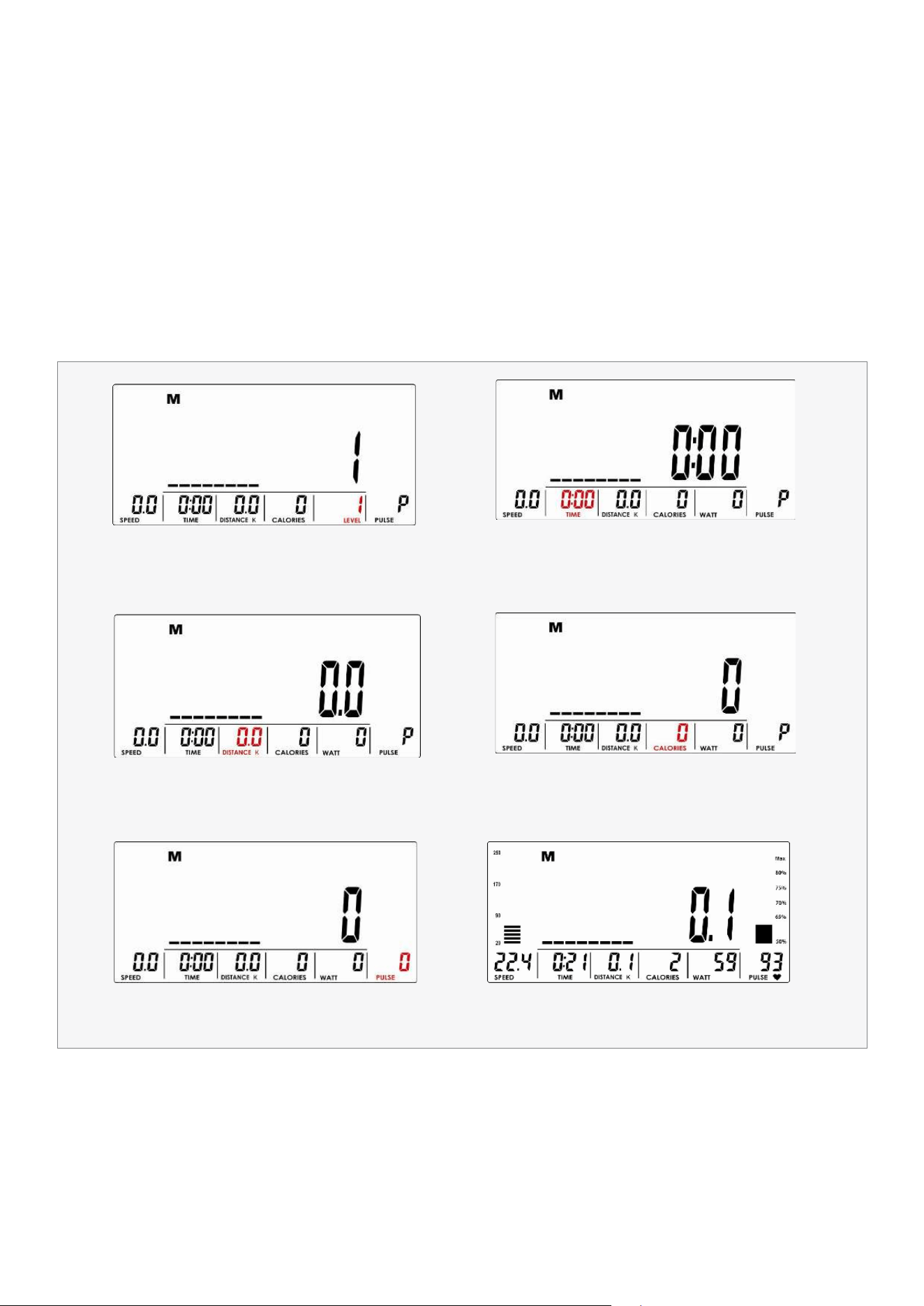
MANUAL MODE
Press START in main menu may start workout in manual mode directly.
1. Use UP or DOWN (Encoder) to select workout program, choose M and press MODE / ENTER to select.
2. Use UP or DOWN (Encoder) to adjust load level (Drawing 4), preset value 1.
3. Use UP or DOWN (Encoder) to set TIME (Drawing 5), DISTANCE (Drawing 6), CALORIES (Drawing 7), PULSE
(Drawing 8) and press MODE / ENTER to confirm.
4. Press START/STOP key to start workout. During workout, user can also adjust load level by using UP or DOWN
(Encoder). Load level display in WATT window, no adjusting for 3s, it will switch to display WATT (Drawing 9).
5. Press START/STOP key to pause workout. Press RESET to reverse to main menu.
Drawing 4
Drawing 6
Drawing 8
Drawing 5
Drawing 7
Drawing 9
17COMPUTER OPERATION |
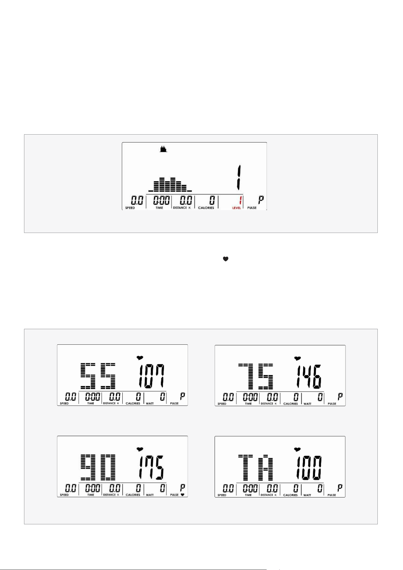
PROGRAM MODE
H.R.C MODE
1. Use UP or DOWN (Encoder) to select workout Program, choose P01 ,P02, P03-P12, and press MODE / ENTER
to select.
2. Use UP or DOWN (Encoder) to adjust load level (Drawing 10), preset value 1.
3. Use UP or DOWN (Encoder) to set TIME.
4. Press START/STOP key to start workout. During workout, user can also adjust load level by using
UP or DOWN (Encoder).
5. Press START/STOP key to pause workout. Press RESET to reverse to main menu.
1. Use UP or DOWN (Encoder) to select workout program, choose (H.R.C) and press MODE / ENTER to select.
2. Use UP or DOWN (Encoder) to select 55% (Drawing 11), 75% (Drawing 12), 90% (Drawing 13) or TAG (TARGET H.R.,
default: 100) (Drawing 14). When select TAG, use UP or DOWN (Encoder) to set value 30~230.
3. Use UP or DOWN (Encoder) to set workout TIME.
4. Press START/STOP key to start or stop workout. Press RESET to reverse to main menu.
Drawing 10
Drawing 11 Drawing 12
Drawing 13 Drawing 14
18 | COMPUTER OPERATION
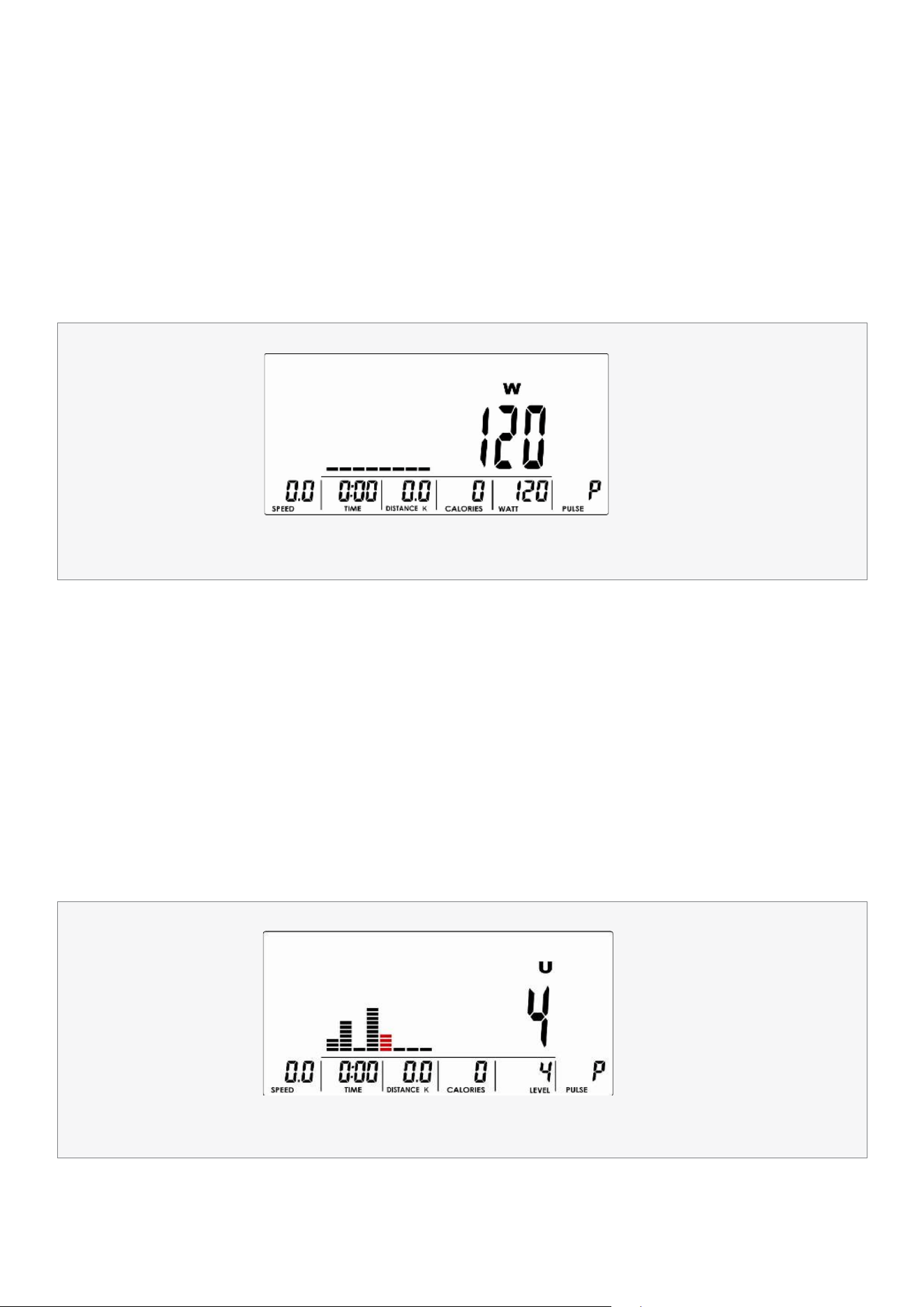
WATT MODE
USER PROGRAM MODE
1. Use UP or DOWN (Encoder) to select workout program, choose W and press MODE / ENTER to select.
2. Use UP or DOWN (Encoder) to set WATT target. (default: 120, Drawing 15).
3. Use UP or DOWN (Encoder) to set TIME.
4. Press START/STOP key to start workout. During workout, system will adjust load level automatically
based on user training status. User can use UP or DOWN (Encoder) to adjust Watt level.
5. Press START/STOP key to pause workout. Press RESET to reverse to main menu.
1. Use UP or DOWN (Encoder) to select workout program, choose U and press MODE / ENTER to get into.
2. Use UP or DOWN (Encoder) to create user profile (Drawing 16). There are total 8 column, user can adjust
each column load level. User can hold MODE / ENTER 2 seconds to quit during setting.
3. Use UP or DOWN (Encoder) to set TIME.
4. Press START/STOP key to start workout. During workout, user can also adjust load level by using
UP or DOWN (Encoder).
5. Press START/STOP key to pause workout. Press RESET to reverse to main menu.
Drawing 15
Drawing 16
19COMPUTER OPERATION |
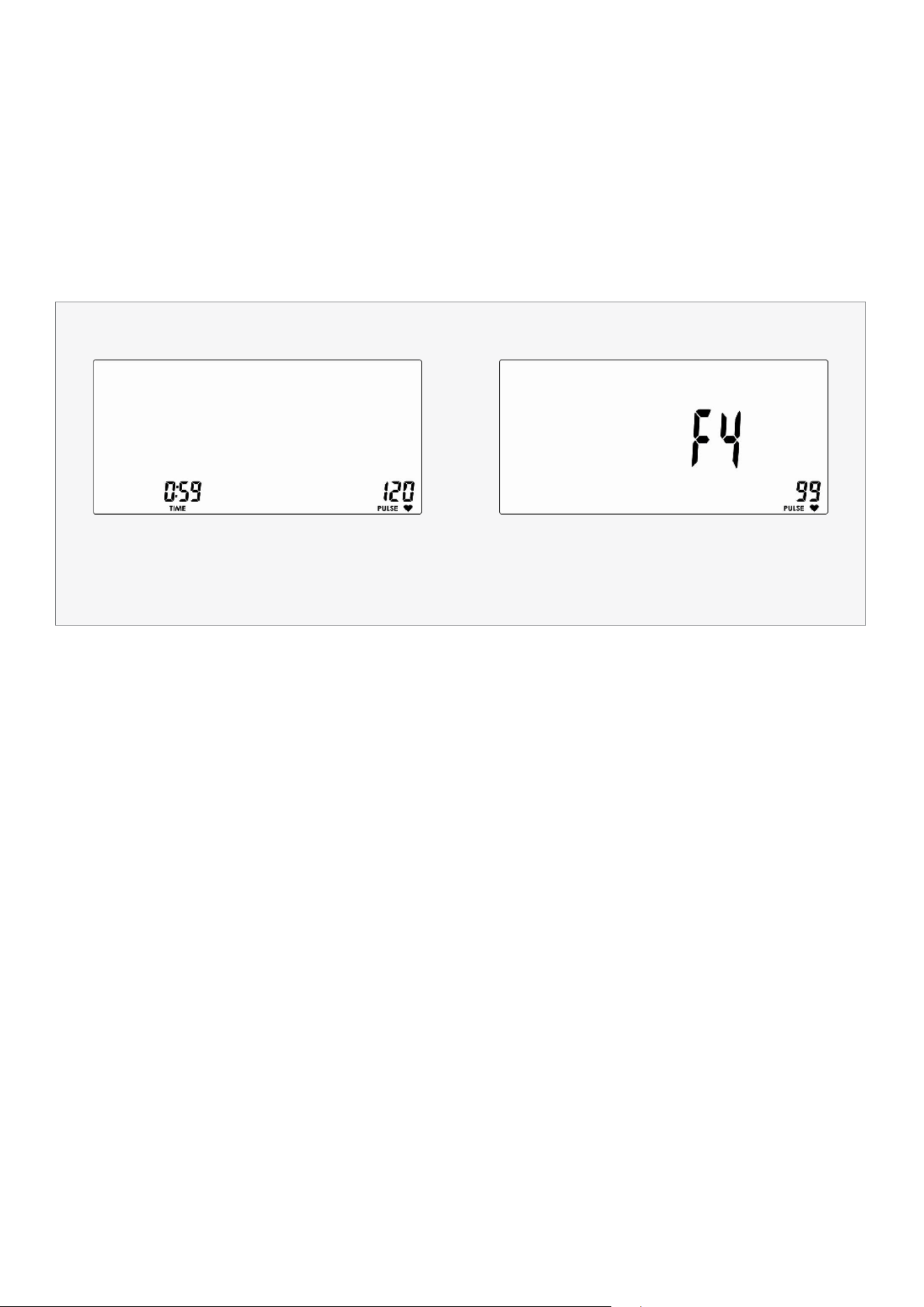
RECOVERY
After exercising for a period, keep holding on hand grips or wearing chest strap and press RECOVERY key. All
function display will stop except "TIME" starts counting down from 00:60 to 00:00 (Drawing 17). Screen will
display your heart rate recovery status with the F1, F2 to F6 (Drawing 18). F1 is the best, F6 is the worst. User may
keep exercising to improve the heart rate recovery status. (Press the RECOVERY key again to return the main
display).
Drawing 17 Drawing 18

20| COMPUTER OPERATION
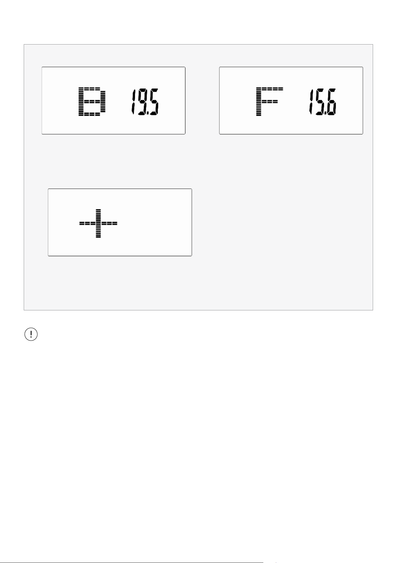
BODY FAT
1. In STOP mode, press the BODY FAT key to start body fat measurement.
2. Console will display UX (Drawing 19) and start measuring (Drawing 20~21).
3. During measuring, users have to hold both hands on the hand grips. When console detect the pulse,
LCD display as (Drawing 22) for 8 seconds until computer finish measuring.
4. LCD will display BMI (Drawing 23), FAT % (Drawing 24) and BODY FAT advice symbol (Drawing 25).
5. Error message:
*The LCD displays "---- " , " ----" – means not hand the grip correctly.
*E-1–There is no heart rate signal input detected.
*E-4–Occurs when FAT% and BMI result is below 5 or exceeds 50.
Drawing 19
Drawing 21
Drawing 20
Drawing 22
21COMPUTER OPERATION |
Drawing 23
Drawing 25
Drawing 24
1. After 4 minutes without pedaling or pulse input, console will enter into power saving mode.
Press any key may wake the console up.
2. When computer act abnormal, please plug out the adaptor and plug in again.
Note:
22| EXERCISE GUIDE
VII. EXERCISE GUIDE
PLEASE NOTE:
Before beginning any exercise program, consult your physician. This is important especially if you are over the
age of 45 or individuals with pre-existing health problems.
The pulse sensors are not medical devices. Various factors, including the user’s movement, may affect the
accuracy of heart rate readings. The pulse sensors are intended only as an exercise aid in determining heart
rate trends in general.
Exercising is great way to control your weight, improving your fitness and reduce the effect of aging and stress.
The key to success is to make exercise a regular and enjoyable part of your everyday life.
The condition of your heart and lungs and how efficient they are in delivering oxygen via your blood to your
muscles is an important factor to your fitness. Your muscles use this oxygen to provide enough energy for daily
activity. This is called aerobic activity. When you are fit, your heart will not have to work so hard. It will pump a lot
fewer times per minute, reducing the wear and tear of your heart.
So as you can see, the fitter you are, the healthier and greater you will feel.
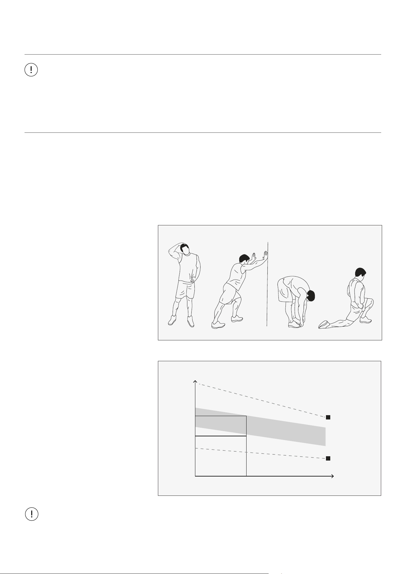
WARM UP
Start each workout with 5 to 10
minutes of stretching and some light
exercises. A proper warm-up increases
your body temperature, heart rate and
circulation in preparation for exercise.
Ease into your exercise.
After warming up, increase the
intensity to your desired exercise
program. Be sure to maintain your
intensity for maximum performance.
Breathe regularly and deeply as you
exercise.
TARGET ZONE
MAXIMUM
85%
70%
COOL DOWN
AGE
HEART RATE
200
180
160
140
120
100
80
20 25 30 35 40 45 50 55 60 65 70 75
WORKOUT GUIDELINES
COOL DOWN
Finish each workout with a light jog
or walk for at least 1 minute. Then
complete 5 to 10 minutes of stretching
to cool down. This will increase the
flexibility of your muscles and will help
prevent post-exercise problems.
This is how your pulse should behave during general fitness exercise. Remember to warm up and cool down
for a few minutes.

23
VII. WARRANTY
AUSTRALIAN CONSUMER LAW
Many of our products come with a guarantee or warranty from the manufacturer. In addition, they come
with guarantees that cannot be excluded under the Australian Consumer Law. You are entitled to a
replacement or refund for a major failure and compensation for any other reasonably foreseeable loss
or damage.
You are entitled to have the goods repaired or replaced if the goods fail to be of acceptable quality and
the failure does not amount to a major failure. Full details of your consumer rights may be found at
www.consumerlaw.gov.au.
Please visit our website to view our full warranty terms and conditions:
http://www.lifespanfitness.com.au/warranty-repairs
WARRANTY AND SUPPORT
Any claim against this warranty must be made through your original place of purchase.
Proof of purchase is required before a warranty claim may be processed.
If you have purchased this product from the Official Lifespan Fitness website, please visit
https://lifespanfitness.com.au/warranty-form
For support outside of warranty, if you wish to purchase replacement parts or request a repair or
service, please visit https://lifespanfitness.com.au/warranty-form and fill in our Repair/Service
Request Form or Parts Purchase Form.
Scan this QR code with your device to go to lifespanfitness.com.au/warranty-form
WARRANTY |

WWW.LIFESPANFITNESS.COM.AU