D. Apply PVC glue to the outside slip surface of the provided slip ring (Fig 14) and insert into the downward
ow end of the AG-2550 in a twisting manner.
E. Check that the sensor body portion is not exceeding 30 degrees of decline from the horizontal. Attach the
remaining (schedule 40) ¾” PVC condensate pipe in a manner that is consistent with recommended industry standards.
2b. Vertical Installation
A. Connect supplied ¾ male threaded straight slip pipe tting (Figure 15) or ¾ male threaded 90 degree slip pipe
tting (Figure 16) to air handler using thread sealant. Use wrench to tighten. Do not over tighten.
B. Make sure the sensor cap of the AG-2550E (Fig 13) has o-ring installed and is properly hand tightened onto
the correct up-facing port. (See Fig 15 or 16)
C. Noting the direction of ow for the 90 degree ow position indicated on the side of the AG2550E, apply PVC
glue to the outside slip surface of the provided slip ring and insert into the inow end of the AG2550E in a
twisting manner.
D. Apply PVC glue to the inside surface of the slip ring(Fig 14) and attach the AG2550E body to the air handler.
E. Check that the AG2550E is perpendicular to the horizontal. Attach the remaining (schedule 40) ¾” PVC
condensate pipe in a manner that is consistent with recommended industry standards.
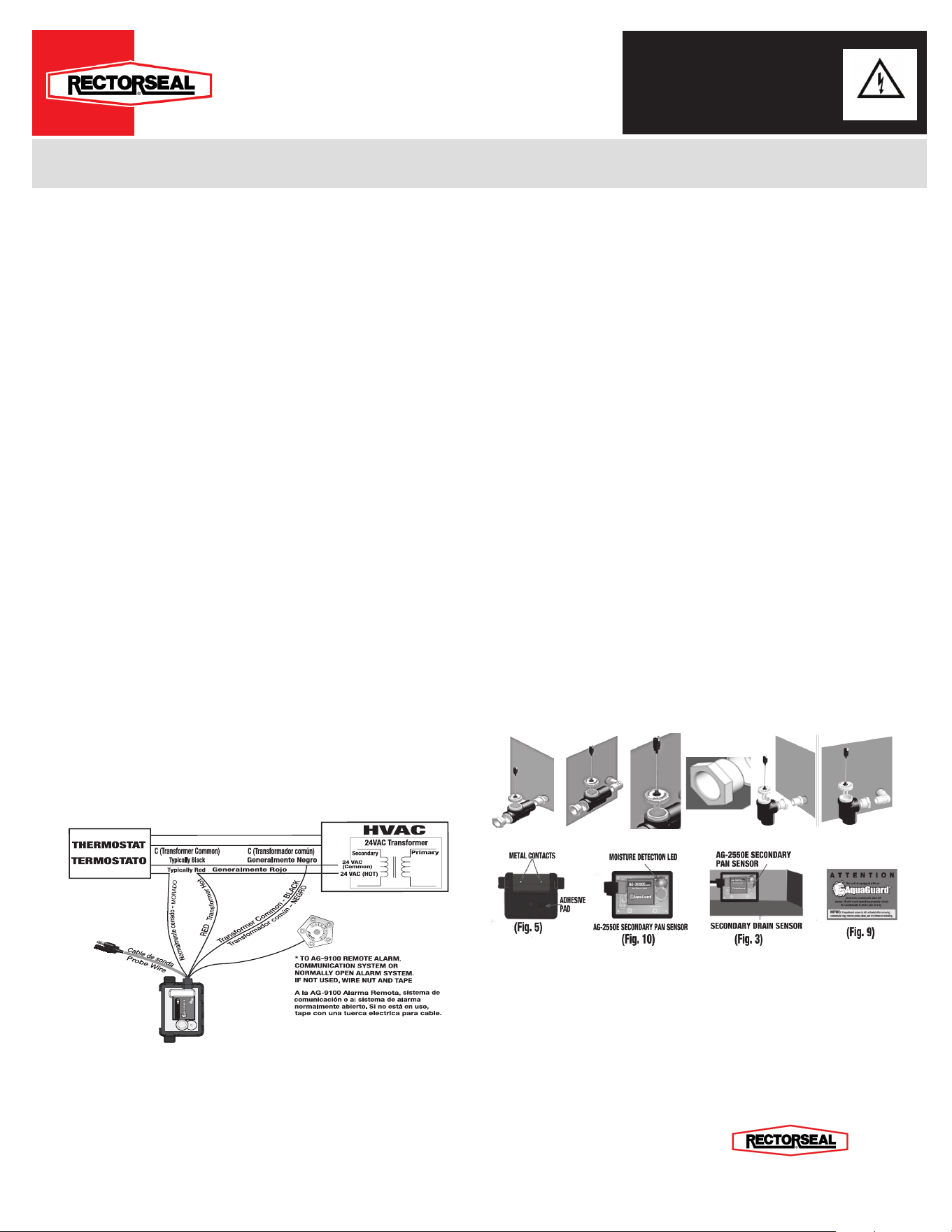
3. Place the ATTENTION sticker on HVAC unit in a clearly visible location (g. 9).
4. Test the HVAC unit by plugging the condensate line and lling the primary drain pan with water. If installed properly,
the HVAC unit will shut down (Time delay up to 60 sec ON/60 sec OFF).
Note: If “Optional Wiring” was chosen, only the compressor will shut-o upon condensate detect. e Air Handler will
continue to run.
Figure 1
N
o
r
m
a
l
l
y
O
p
e
n
W
H
I
T
E
N
o
r
m
a
l
m
e
n
t
e
a
b
i
e
r
t
o
-
B
L
A
N
C
O
AG-3000E
24 VAC,
5.0 Amps Carry
N
o
r
m
a
l
l
y
C
l
o
s
e
d
-
P
U
R
P
L
E
T
r
a
n
s
f
o
r
m
a
d
o
r
c
a
l
i
e
n
t
e
-
R
O
J
O
Work Safe, READ THIS!
ATTENTION: FAILURE TO READ AND COMPLY WITH ALL WARNINGS, CAUTIONS AND INSTRUCTIONS PRIOR TO STARTING INSTALLATION MAY CAUSE PERSONAL INJURY AND/OR PROPERTY DAMAGE AND
VOID WARRANTY.
STOP/READ: is device must be installed in accordance with manufacturer’s instructions. is unit must be in accordance with all applicable local plumbing, drainage and electrical codes.
WARNING: Remove electrical shock hazard – DISCONNECT THE POWER SUPPLY BEFORE INSTALLING AQUAGUARD to avoid electrical shock and/or equipment damage. Do not use on circuits exceeding 24 volts to avoid damage to
switch, shock or re hazard.
CAUTION: In some situations the switch may cause the unit to rapidly cycle on and o as water level rises slowly in pan. Aer a brief period the unit will switch totally o. condensation drain must be serviced if this occurs.
CAUTION: In any installation where property damage and/or personal injury might result from an inoperative switch due to power outages, a back-up system(s) and or alarm should be installed.
NOTICE: e AquaGuard AG-2550E must be only installed by a licensed contractor or under the direct supervision of same. Condensation pan must be properly maintained aer installation and be kept free from foreign objects, rust or other
obstructions that might interfere with the proper operation of the AquaGuard device.Disconnect power to unit at main panel. Disconnect power to the low voltage thermostat circuit.
WIRING THE AG- 2550E:
(To ensure proper performance of product, instructions must be followed.)
1. Ensure the power is disconnected to the HVAC unit at the main electrical panel prior to moving to step 2. For
Breaking “Wall ermostat” Power Wire (see Figure 1)
2. In HVAC Unit locate 24 VAC Power wire going to “Wall ermostat”, (Typically RED). Break/Disconnect 24 VAC
Power wire going to “Wall ermostat”.
A. Connect “RED”, “Input: 24 VAC (Hot)” wire of AG-2550E to 24 VAC (Hot) secondary side of 24 VAC Transformer.
B. Connect “PURPLE”, “Normally Closed” wire of AG-
2550
E to ermostat’s “R” Terminal.
NOTE: “PURPLE” wire must be connected to “THERMOSTAT”. Maximum capacity 24VAC/5Amp.
C. Connect “BLACK”, “Input: 24 VAC (Common)” wire of AG-
2550
E to 24 VAC (COMMON) secondary
side of 24 VAC Transformer or ermostat’s “C” Terminal.
D. “WHITE”, “Normally Open” wire of AG-
2550
E must be connected to AquaGuard, AG-9100 External
Alarm (see Figure 1) or Home Alarm System, or Communicating System, etc..
CAUTION: “WHITE”, “Normally Open” wire maximum capacity, 24VAC/1Amp.
Note: When AG-
2550
E is wired correctly, the HVAC unit will shut-o upon condensate detection.
Note: AG-
2550
E time delay up to 60 sec ON.
Optional Wiring: For Breaking Compressor Wire
3. In HVAC Unit locate “Compressor wire going to “Wall ermostat”, typically (YELLOW). Break/Disconnect
Compressor wire going to “Wall ermostat”.
A. Connect typically “YELLOW” wire, going to “Wall ermostat” to “RED”, “Input: 24 VAC (Hot)” wire of
AG-
2550
E .
B. Connect “PURPLE”, “Normally Closed” wire of AG-
2550
E to Compressor’s typically “YELLOW” wire going
to Compressor.
NOTE: “PURPLE” wire must be connected to COMPRESSOR “YELLOW” Wire. Maximum capacity 24VAC/5Amp.
C. Connect “BLACK”, “Input: 24 VAC (Common)” wire of AG-
2550
E to 24 VAC (COMMON) secondary side
of 24 VAC Transformer or ermostat’s “C” Terminal.
D. “WHITE”, “Normally Open” wire of AG-
2550
E must be connected to AquaGuard, AG-9100 External Alarm
(see Figure 1) or Home Alarm System, or Communicating System, etc..
CAUTION: “WHITE”, “Normally Open” wire maximum capacity, 24VAC/1Amp.
Note: When the AG-
2550
E is wired correctly, (ONLY) the Compressor will shut-o upon condensate detection. Air
Handler will continue to run.
NOTE: AG-
2550
E time delay up to 60 sec ON.
4. Test the AG-
2550
E Secondary Pan Sensor (At start-up check initial amperage load) while the HVAC unit is on and
functioning correctly. See installation of the AG-
2550
E:
HVAC Installation w/ optional external alarm or accessory
Installation of the AG-2550E control box:
(To ensure proper performance of product, instructions must be followed.)
1. Clean desired mounting area with included alcohol pad.
2. Using the double-sided tape provided with the AG-2550E, ax the mounting bracket in the lowest point of the pan
within 25” of the secondary drain port (g. 2) and snap AG-2550E Secondary Pan Sensor into mounting bracket.
A. Note: If not using a secondary drain pan, AG-2550E Secondary Pan Sensor may be mounted to the side of
the HVAC unit using the double-sided tape or mounting bracket. (g.3)
3. Test the AG-2550E control box: Place Control Box in pan, add enough water to the pan to cover contacts for at least
60 seconds. LED will iluminate and HVAC unit will stop running if wired correctly.
4. Place the included ATTENTION sticker on HVAC unit in a clearly visible location (g. 9).
Installation of the AG2550E In-line sensor
1. Couple the probe sensor to the ”Y Cable” using the one-way connector (g. 19)
2a. Horizontal Installation
A. Connect supplied ¾ male threaded straight slip pipe tting (Figure 11) or ¾ male threaded 90 degree slip
pipe tting (Figure 12) to air handler using thread sealant. Use wrench to tighten. Do not over tighten.
B. Make sure the sensor cap of the AG-2550E (Fig 13) has o-ring installed and is properly hand tightened onto
the correct up-facing port. (See Fig 11 or 12)
C. Noting the direction of ow for the horizontal position indicated on the side of the AG-2550E, apply PVC glue
to the end opposite the horizontal arrow and mate to the air handler in a twisting motion, making sure the
clean out port/sensor cap port is le facing the up position.
(Fig 11) (Fig 12)
(Fig 13)
(Fig 14)
(Fig 15)
(Fig 16)
Installation Instructions
Wiring the AquaGuard
®
AG-2550E - Primary Drain Pan Water Sensor
AG-2550E
2601 Spenwick Drive, Houston, TX 77055
(P) 800-231-3345 (F) 800-441-0051 www.rectorseal.com

LIMITED WARRANTIES AND LIMITATION OF LIABILITY
REGISTER YOUR PRODUCT ONLINE: www.rectorseal.com
1 YEAR SWITCH AND SENSOR LIMITED WARRANTY AND LIMITATION OF LIABILITY
The limitations of liability set forth below include body and all component parts as well as the product itself as a whole.
Rectorseal warrants to the original consumer purchaser (“Purchaser) of its AquaGuard switch and sensor products, that they are free from
defects in material or workmanship for a period of one (1) year from the date of purchase. If this product shall prove to be defective within
the one (1) year period from the date of purchase, it shall be repaired or replaced, at Rectorseal ‘s option, subject to the GENERAL TERMS
and CONDITIONS set forth below.
EXCLUSIONS
This warranty does not cover damages resulting from use of components or accessories not approved by Rectorseal.
3, and 10 YEAR SECONDARY DRAIN PAN LIMITED WARRANTY AND LIMITATION OF LIABILITY
This warranty applies only to secondary drain pans installed in the United States and Canada.
Rectorseal warrants to the original consumer purchaser (“Purchaser”) of its AquaGuard secondary drain pan products, that they are free from
defects in material or workmanship for a period of three (3) years for Titan pan models, ten (10) years for Goliath and Goliath Furnace
models, from the date of purchase. If this product shall prove to be defective within the three, five or ten (3, or 10) year period from the date
of purchase, it shall be repaired or replaced, at Rectorseal’s option, subject to the GENERAL TERMS and CONDITIONS set forth below.
This warranty extends only to the original consumer purchaser and is nontransferable.
EXCLUSIONS
This warranty does not cover damages resulting from the use of corrosive material (including, but not limited to: Acetone, MEK and petro-
leum-based products); nor damages resulting from use of components or accessories not approved by Rectorseal.
GENERAL TERMS AND CONDITIONS
To be eligible for the warranty the purchaser must provide Rectorseal with the following:
1. Proof of Purchase (Original Receipt)
2. Installer’s Testimony
3. Original Product
4. Original Work Order
5. Photos of Installation
PURCHASER MUST PAY ALL LABOR AND SHIPPING CHARGES NECESSARY TO REPLACE PRODUCT COVERED BY THIS WAR-
RANTY. This warranty shall not apply to acts of God, nor shall it apply to products which, in the sole judgment of Rectorseal have been subject
to negligence, abuse, accident, tampering, misapplication, alteration; nor due to improper installation, operation or maintenance or storage; nor
moved from its original place of installation; nor to other than normal application, use or service, including but not limited to, operational failures
caused by corrosion, rust or other foreign materials in the system. Requests for service under this warranty shall be made by returning the de-
fective product to the Retail outlet or to Rectorseal as soon as possible after the discovery of any alleged defect. Rectorseal will subsequently
take corrective action as promptly as reasonably possible. No requests for service under this warranty will be accepted if received more than
thirty-one (31) days after the term of the warranty.1hiswarranty sets forth Rectorseal’s sole obligation and purchaser’s exclusive remedy for de-
fective products. For your benet and protection register your product online at www.rectorseal.com within thirty (30) days of installation. This
will initiate the Warranty period and will allow us to contact you, should it become necessary. In the absence of a recorded product registration,
the Warranty period will begin upon product shipment from Rectorseal. In the event that Rectorseal attempts to contact consumers regarding
a recall or other matter, and any damages occur, which could have been avoided by registration by the consumer, Rectorseal shall have no
liability. IN ALL CIRCUMSTANCES, RECTORSEAL’S MAXIMUM LIABILITY SHALL NOT EXCEED THE ACTUAL PURCHASE PRICE
PAID FOR THE PRODUCT ALONE. Warranty claims must be registered with Rectorseal within thirty (30) days of damage or malfunction.
Rectorseal reserves the right to visit the site of the installation or to require documentation of the claim before assuming any responsibility
under the provisions of this Warranty.Consumer agrees to inspect the product at the time of installation for any reasonable discernable defects
and, further, agrees to inspect the product annually. Any damages occurring, which could have been avoided by proper inspection will not be
the responsibility of Rectorseal. RECTORSEAL SHALL NOT BE LIABLE FOR ANY CONSEQUENTIAL, INCIDENTAL, OR CONTINGENT
DAMAGES WHATSOEVER TO THE PURCHASER OR ANY THIRD PARTY.THE FOREGOING WARRANTIES ARE EXCLUSIVE AND IN
LIEU OF ALL EXPRESSED WARRANTIES. IMPLIED WARRANTIES, INCLUDING BUT NOT LIMITED TO THE IMPLIED WARRANTIES OF
MERCHANTABILITY AND FITNESS FOR A PARTICULAR PURPOSE, SHALL NOT EXTEND BEYOND THE DURATION OF THE APPLICA-
BLE EXPRESSED WARRANTIES PROVIDED HEREIN.
Some states do not allow the exclusion of limitation of incidental and consequential damages or limitations on how long an implied
warranty lasts, so the above limitations or exclusions may not apply to you. This warranty gives you specic legal rights and you may also
have other legal rights that vary from state to state.
VENUE: Any purchaser or third party actions brought for any reason hereunder shall be commenced in Houston, TX and no other jurisdiction,
and such action shall be governed by and construed in accordance with the laws of the State of Texas. Any notice herein shall be sent by
certied or registered mail to 2601 Spenwick Drive, Houston, TX USA
24 VAC, 5 amps
RectorSeal® Houston, TX USA www.rectorseal.com US Patent Pending