
19" Electric Mower MEC1218E
Read all safety rules and instructions carefully before operating this tool.
Distributed By Cleva North America 601 Regent Park Court Greenville, SC 29607 (866)-384-8432
Lisez attentivement toutes les consignes de sécurité ainsi que les instructions avant de faire fonctionner cet outil.
Distribué par Cleva North America 601 Regent Park Court Greenville, SC 29607 (866)-384-8432
MNL_MEC1218E_V1
EN p. 2
Operators Manual / Manual de uso
Cortadora de césped eléctrica de 19” MEC1218E
ES p. 29
By Ben Means at 4:43 pm, Dec 06, 2017

2
CONTENTS
SPECIFICATIONS
INTRODUCTION
GENERAL SAFETY RULES
SPECIFIC SAFETY RULES
SYMBOLS
ELECTRICAL
FEATURES
ASSEMBLY
OPERATION
MAINTENANCE
TROUBLESHOOTING
WARRANTY
EXPLODED VIEW / PARTS LIST
NOTES
2
2
3
3-5
5-6
7-8
9-10
11-12
13-16
17-18
19-23
24
25
26-27
28
TABLE OF CONTENTS
SPECIFICATIONS
Electric Mower MEC1218E
Voltage 120V~60Hz
Electricity 12.5 A
Motor Speed 3800 /min
Deck Width 19 inch (483mm)
Cutting Width 18 inch (457mm)
Cutting Height Adjustment 1.4-3.4 inch (35-85mm); 6 levels
Collection Bag Capacity 16 gallon (60liters)
Wheel Size 7 inch Front / 9 inch Rear (170/235mm)
Weight 34 lbs (15.4 kg)
GENERAL SAFETY RULES
3
INTRODUCTION
WARNING
READ ALL INSTRUCTIONS
observe all safety instructions could result in serious injury or death.
lawn mower
enters the area.
than the operator.
slippery surfaces.
This product has many features for making its use more pleasant and enjoyable. Safety,
performance, and dependability have been given top priority in the design of this product making
it easy to maintain and operate.
READ AND UNDERSTAND ALL INSTRUCTIONS.
and/or serious personal injury.
4
GENERAL SAFETY RULES
operating this product.
order.
removing the grass catcher, or unclogging the discharge guard.
children.
immediately. Damaged cords increase the risk of electric shock.
SW, SOW, STW, STOW, SJW, SJOW, SJTW,
or SJTOW.
GENERAL SAFETY RULES
5
SPECIFIC SAFETY RULES
be used for this measure of safety.
from oil or grease.
accessories approved by the manufacturer.
accident.
direction on slopes.
accident. Walk, never run.

SPECIFIC SAFETY RULES
6
before removing the grass catcher or unclogging the chute. The cutting blade continues to rotate
until you are sure the blade has stopped rotating.
accidentally.
create a risk of serious injury to the user, or damage to the product.
authorized service center to avoid risk.
this product. If you loan someone this tool, loan them these instructions also.
7
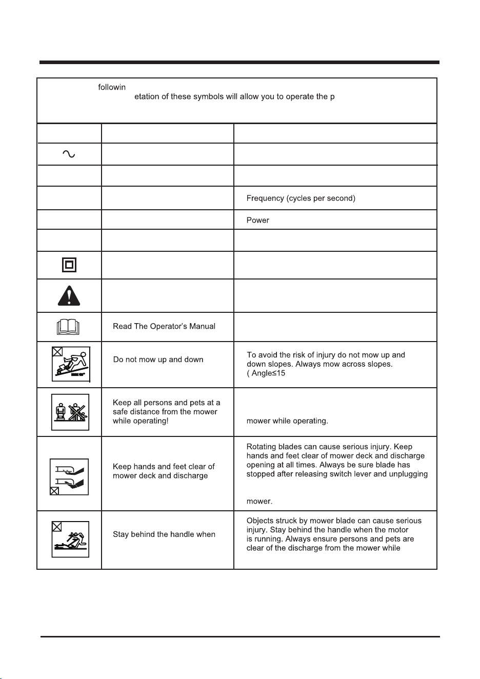
SYMBOLS
Some of the g symbols may be used on this product. Please study them and learn their
meaning. Proper interpr
roduct better and safer.
NOITANALPXE/NOITANGISEDEMANLOBMYS
V
zH
W
s
r
h
Volts
slopes!
the motor is running!
opening at all times!
Safety Alert
Class II Construction
Hours
Watt
Hertz
Alternating Current
You must read the operating instructions carefully.
Precaution that involves your safety.
°
)
To avoid the risk of injury to bystanders keep all
persons and pets at a safe distance from the
operating.
before removing and replacing grass catcher,
cleaning, servicing, transporting or lifting the
Voltage
Double-insulated construction
Time
Type of current
A
tnerruCserepmA
8
SYMBOLS
SERVICE
repair. When servicing, use only identical replacement parts.
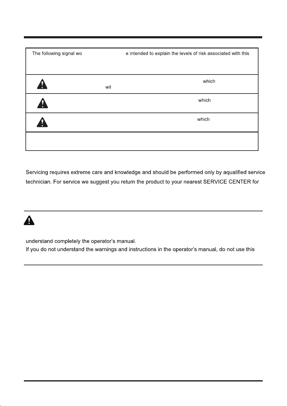
SYMBOL SIGNAL MEANING
DANGER:
Indicates an imminently hazardous situation, , if not avoided,
l result in death or serious injury.
WARNING:
Indicates a potentially hazardous situation, , if not avoided,
could result in death or serious injury.
CAUTION:
Indicates a potentially hazardous situation, , if not avoided, may
result in minor or moderate injury.
CAUTION:
(Without Safety Alert Symbol) Indicates a situation that may result in
property damage.
rds and meanings ar
product.
WARNING
To avoid serious personal injury, do not attempt to use this product until you read thoroughly and
product. Call customer service for assistance. (866) 384-8432
WARNING
9
ELECTRICAL
DOUBLE INSULATION
insulation. Double insulated tools do not need to be grounded.
The double insulated system is intended to protect the user from shock resulting from a break in the
NOTE:
ELECTRICAL CONNECTION
volts, 60 Hz, AC only (normal household current). Do not operate this product on direct current (DC).
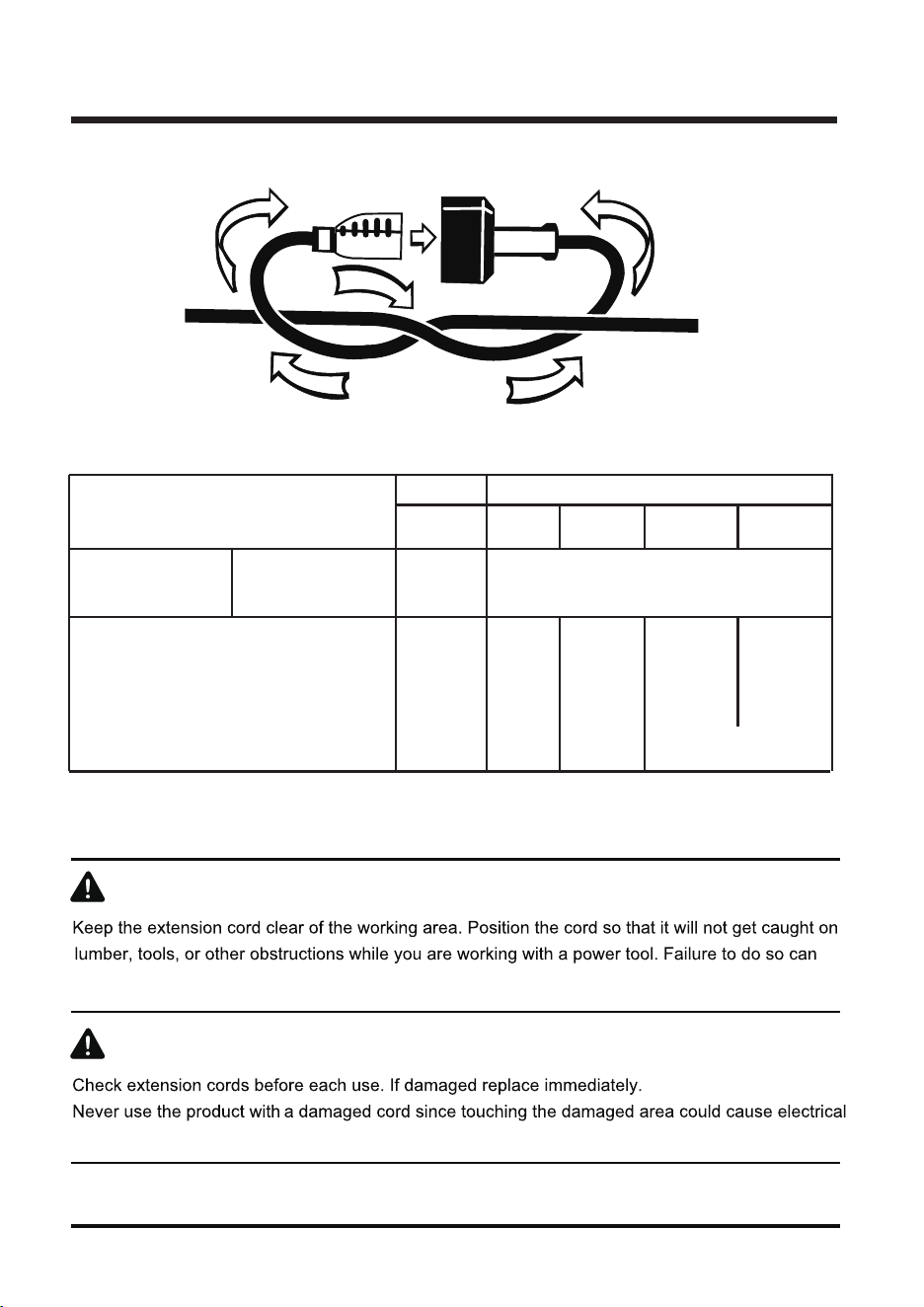
EXTENSION CORDS
10
ELECTRICAL
WARNING
WARNING
result in serious personal injury.
shock resulting in serious injury.
Volts
120V
18
18
16
14
0 - 6
6 - 10
10 - 12
12 - 16
16
16
16
12
16
14
14
14
12
12
25 50 100 150
Total length of cord feet
Not Recommended
AWG
Ampere rating
more than
Ampere rating
not more than
11
FEATURES
Fig. 1
7
14
15
1
2
5
16
6
3
4
8
9
11
10
13
12a
12
NOTE: the above parts and their associated number/letters will be used throughout this manual to
identify parts.
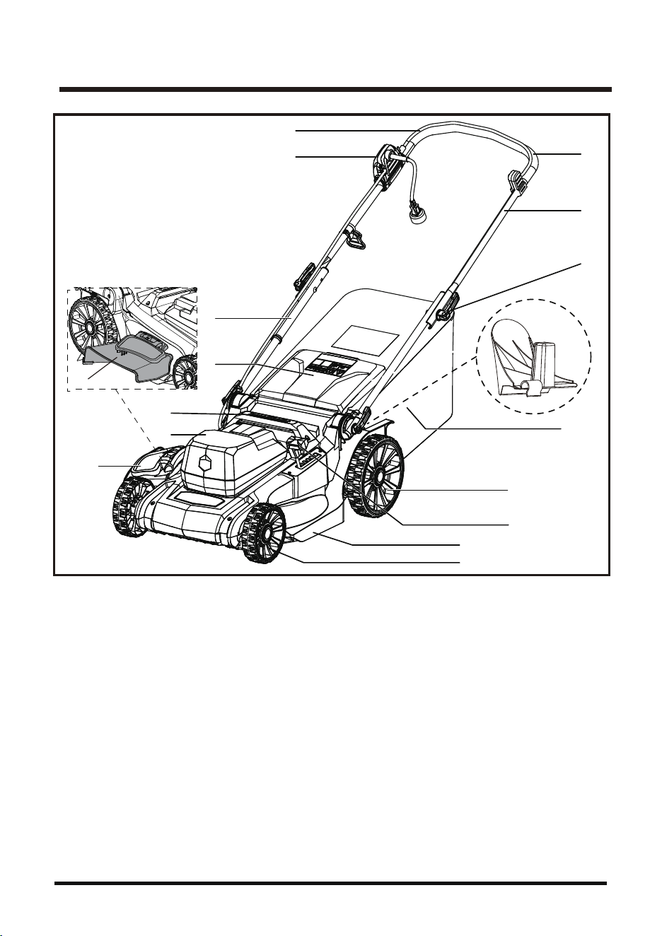
KNOW YOUR LAWN MOWER (See Fig 1)
The safe use of this product requires an understanding of the information on the product and in this
operator’s manual as well as a knowledge of the project you are attempting.
Before use of this product, familiarize yourself with all operating features and safety rules.
1. Start/stop Bale Switch
2. Foam Grip
3. Upper Handle
4. Safety Switch Button
5. Cam locks
6. Collection Bag
7. Mulching Plug
8. Lower Handle
9. Safety Flap
10. Mower Carry Handle
11. Motor Housing
12. Side Discharge Door
12a. Side Discharge Chute
13. Cutting Height
Adjustment Lever
14. Deck
15. Front Wheels
16. Rear Wheels

12
FEATURES
PACKING LIST
Mulching Plug (Comes installed from factory at rear of mower)
Side Discharge Chute
Unpack
This product requires assembly.
■ Carefully remove the product and any accessories from the box. Make sure that all items listed in
the packing list are included. Look under the interior bottom carton flaps for any missing small items.
■ Inspect the product carefully to make sure no breakage or damage occurred during shipping.
■ Do not discard the packing material until you have carefully inspected and satisfactorily operated
the product.
■ If any parts are damaged or missing, please call 866-384-8432.
YOU WILL NEED (ITEMS NOT SUPPLIED)
■ Screwdriver, flat head
■ Suitable personal protective equipment
■ Wrench or socket
■ Pliers
13
ASSEMBLY
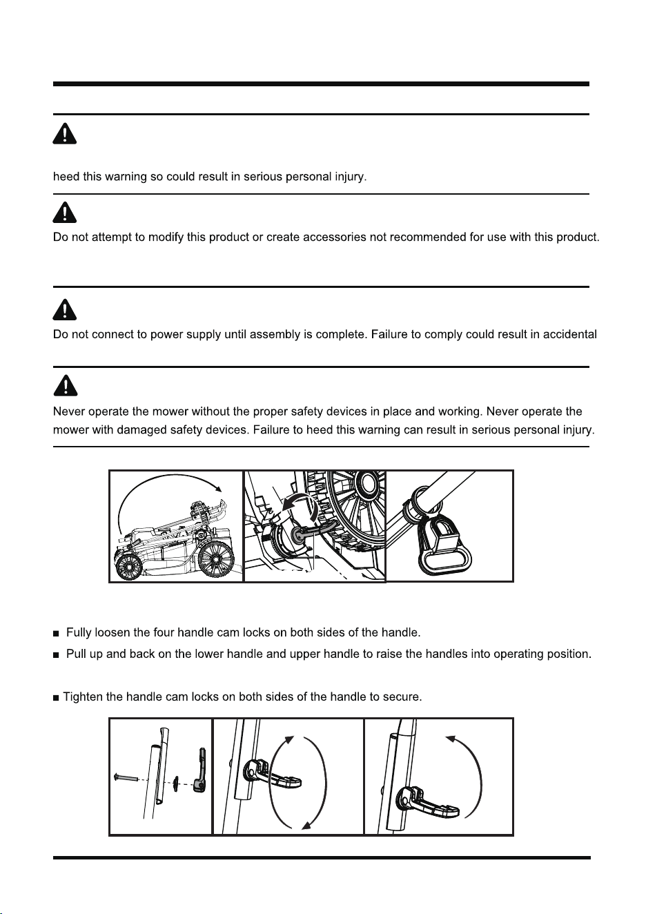
ADJUSTING HANDLE (See Figs. 2-7)
Make certain the handles snap.
WARNING
If any parts are damaged or missing do not operate this product until the parts are replaced. Failure to
WARNING
Any such alteration or modification is misuse and could result in a hazardous condition leading to
possible serious personal injury.
WARNING
starting and possible serious personal injury.
WARNING
Handle Cam Locks
Fig. 2
Fig. 5 Fig. 6 Fig. 7
Fig. 3 Fig. 4
Rod
Holder
ASSEMBLY
14
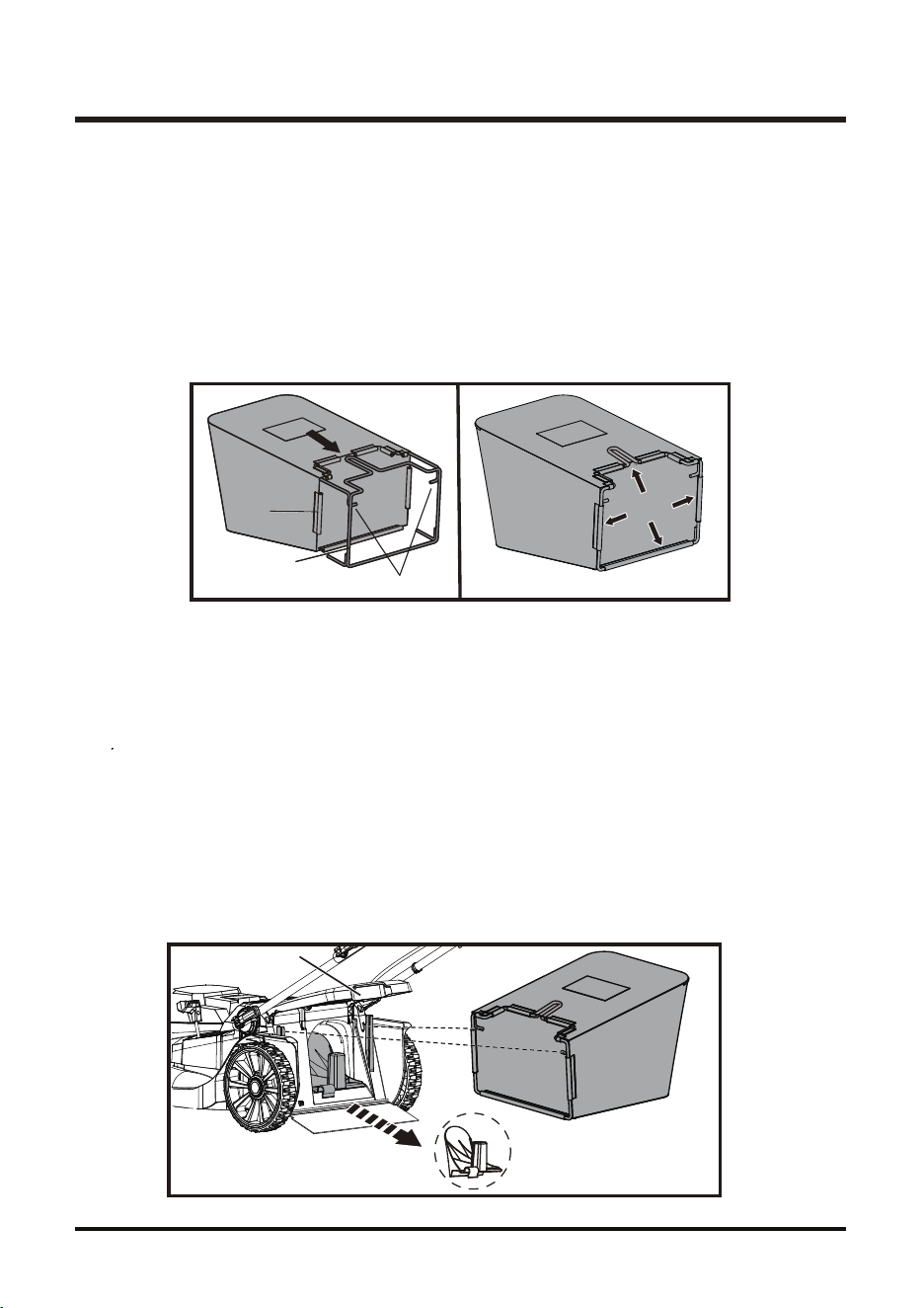
ASSEMBLING THE COLLECTION BAG (See Figs. 8-9)
Your LawnMaster
®
mower comes with a tool-less collection bag.
To assemble:
■ Check the collection bag before assembling to make sure there is no damage.
■ Pull the collection bag over the steel frame as shown.
■ Pry open the soft plastic clamping sleeves with your fingers and insert the steel frame into the
sleeves as shown. Ensure all sleeves are properly clamped with your fingers on the frame.
■ The completely assembled collection bag is shown as below.
INSTALLING THE COLLECTION BAG (See Fig. 10)
NOTE: When using the collection bag, do not install the mulching plug (7). Mulching plug MUST
be removed prior to installing collection bag.
■ Lift the rear safety flap (9) and hold it in position.
■ Lift the collection bag by its handle, hook the rods of collection bag on the mower holder under
rear safety flap.
■ Release the rear safety flap.
■ Make sure both rods are firmly seated on the holder and rear safety flap (9) rests firmly against
the top of the collection bag.
NOTE: Under normal usage, bag material is subject to wear. To
reduce the risk of injury, frequently
inspect the bag assembly and replace if there are any signs of wear or deterioration.
Fig. 8 Fig. 9
Steel Frame
Sleeve
Fig. 10
Mulching plug must be removed
prior to installing collection bag.
Rods
15
ASSEMBLY
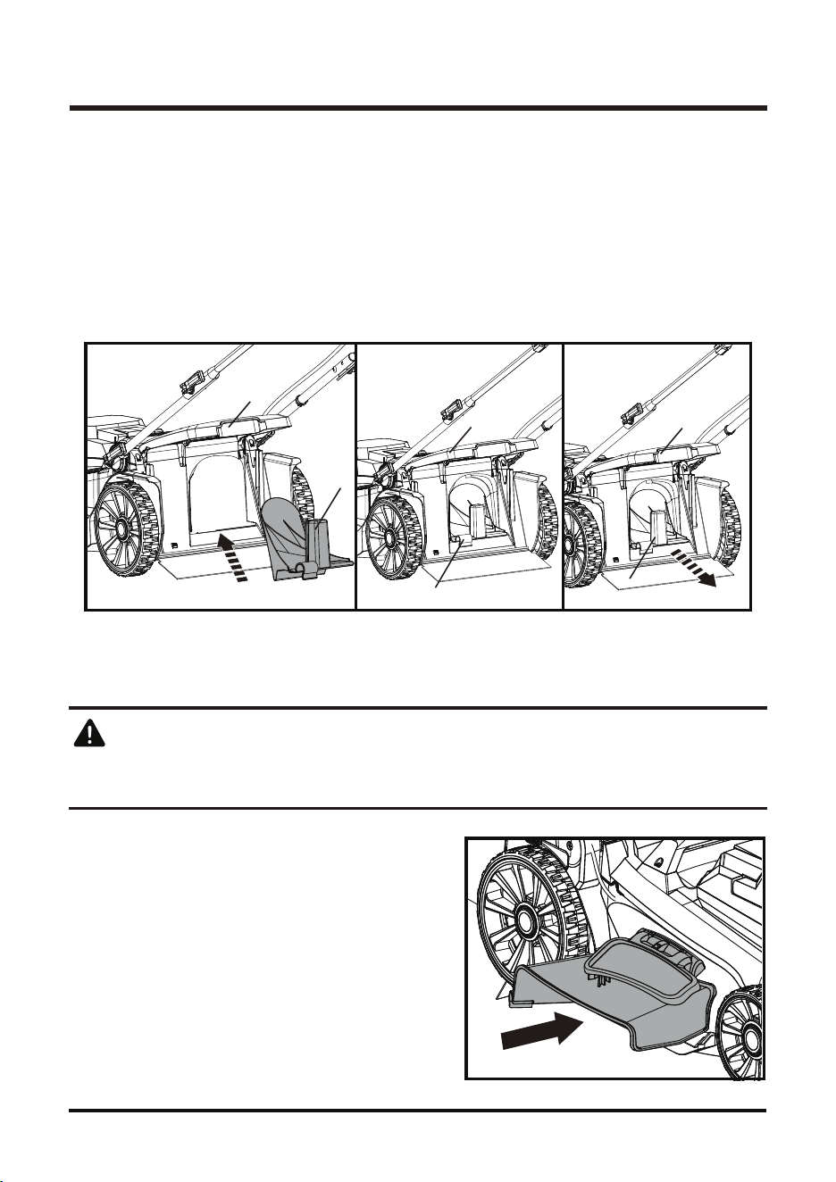
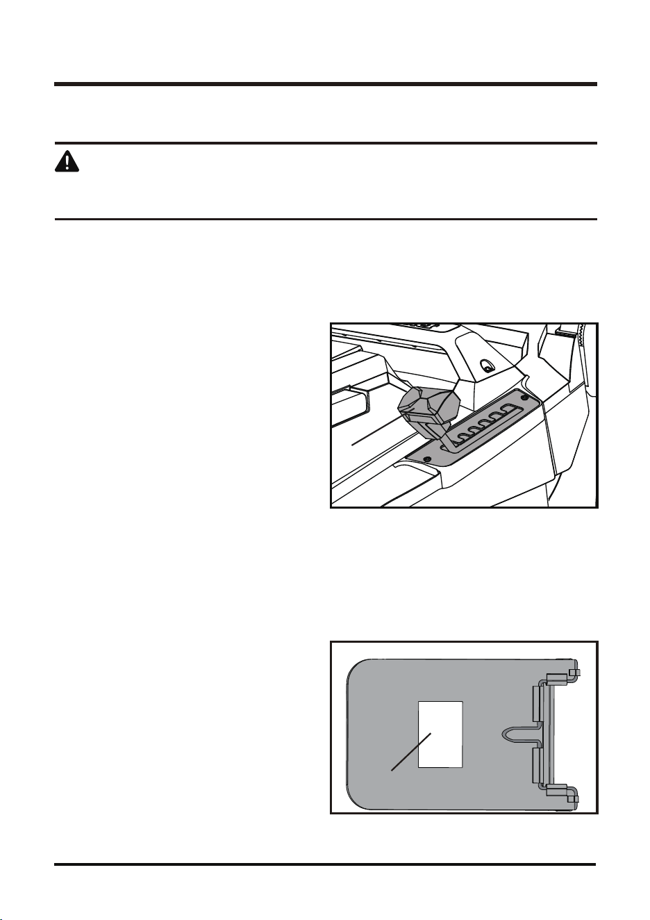
ATTACHING/REMOVING THE MULCHING PLUG (See Figs. 11-13)
Do not at any time make any adjustment to the lawn mower without first stopping the motor and
disconnecting the plug form power source.
The mower is designed to disperse the clippings
back to the lawn. Pull up the side discharge door and
insert the side discharge chute. The side discharge is
optional, if you do not need, you can take it off.
WARNING
NOTE: Mulch plug MUST be removed if collection bag is used during mowing operation.
The mulching plug (7) prevents grass from being collected by blocking the collection chute.
This allows the grass clippings to be deposited back on the lawn during cutting.
■ Lift the safety flap (9) and detach the grass collection bag.
■ Open the safety flap (9), hold it in position and insert the mulching plug into the rear discharge
chute (Fig. 12). Ensure the locking button snaps into place, as picture shown (Fig. 13).
■ Press the locking button to release and remove the mulching plug (Fig. 14).
INSTALLING THE SIDE DISCHARGE CHUTE (See Fig. 14)
Fig. 11 Fig. 12 Fig. 13
7
7
7
9
9
9
Fig.14
16
ASSEMBLY
COLLECTION BAG VIEW WINDOW (See Fig. 16)
■ The collection bag is equipped with a clear view window through which user can observe the filling
condition during the mowing process.
■ Empty the collection bag in time when there is a sign that collection bag is full or nearly full by
observing the view window.
EMPTYING
■ Lift the collection bag by its handle and lift to
remove from mower.
■ Empty grass clippings.
■ Lift the safety flap (9) and reinstall the
collection bag as described earlier in this
manual.
Fig. 15
Fig. 16
View Window
13
SETTING CUTTING HEIGHT
(See Fig. 15)
Do not at any time make any adjustment to the lawn mower without first stopping the motor and
disconnect the plug form power source.
When shipped, the rear wheels on the mower are set to a low-cutting position. Before using the
mower
for the first time, adjust the cutting position to the height best suited for your lawn.
The mower can be set to 6 cutting heights between 1.4” (35mm) and 3.4” (85mm). 6 is the highest setting,
1 is the lowest. Choose the proper cutting height according to the types and conditions of the grass.
To set the cutting height:
■ To raise the cutting height, grasp the cutting
height adjust ment lever, then move it
toward the
back of the mower and engage
the lever in the desired cutting height position
on the mower deck.
■ To lower the cutting height, grasp the cutting
height adjustment lever, then move it
toward the
front of the mower and engage
the lever in the desired cutting height position
on the mower deck.
WARNING
17
APPLICATIONS
OPERATION
fraction of a second is sufficient to inflict serious injury.
WARNING
WARNING
Do not use any attachments or accessories not recommended by the manufacturer of this product.
The use of attachments or accessories not recommended can result in serious personal injury.
WARNING
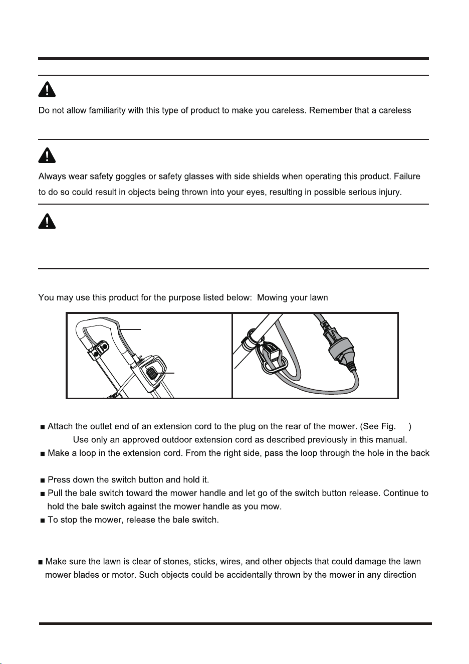
STARTING/STOPPING THE MOWER (See Fig. 17)
NOTE:
of cord retainer and place it around the hook.
NOTE:
A high-pitched noise and sparking may occur as the electric motor decelerates. This is normal.
MOWING TIPS
and cause serious personal injury to the operator and others.
Switch Button
Bale Switch
Fig. 18Fig. 17
18
18
OPERATION
the cord retainer provided.
discharge of the clippings.
clippings.
any other accumulated debris.
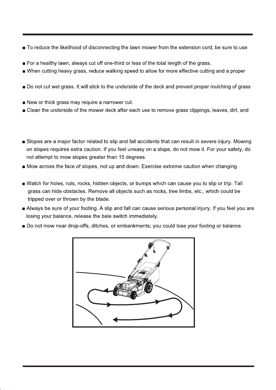
MOWING ON A SLOPE (See Fig. 19)
direction on slopes.
Fig. 19
19
MAINTENANCE
GENERAL MAINTENANCE
various types of commercial solvents and may be damaged by their use. Use clean cloths to remove
dirt, dust, oil, grease, etc.
When servicing, use only identical replacement parts. Use of any other parts may create a hazard
or cause product damage.
WARNING
LUBRICATION
the life of the unit under normal operating conditions. Therefore, no further bearing lubrication is
oil. See Replacing the Cutting Blade for instructions on removing the blade.
Do not use any attachments or accessories not recommended by the manufacturer of this product.
The use of attachments or accessories not recommended can result in serious personal injury.
WARNING
WARNING
ensure
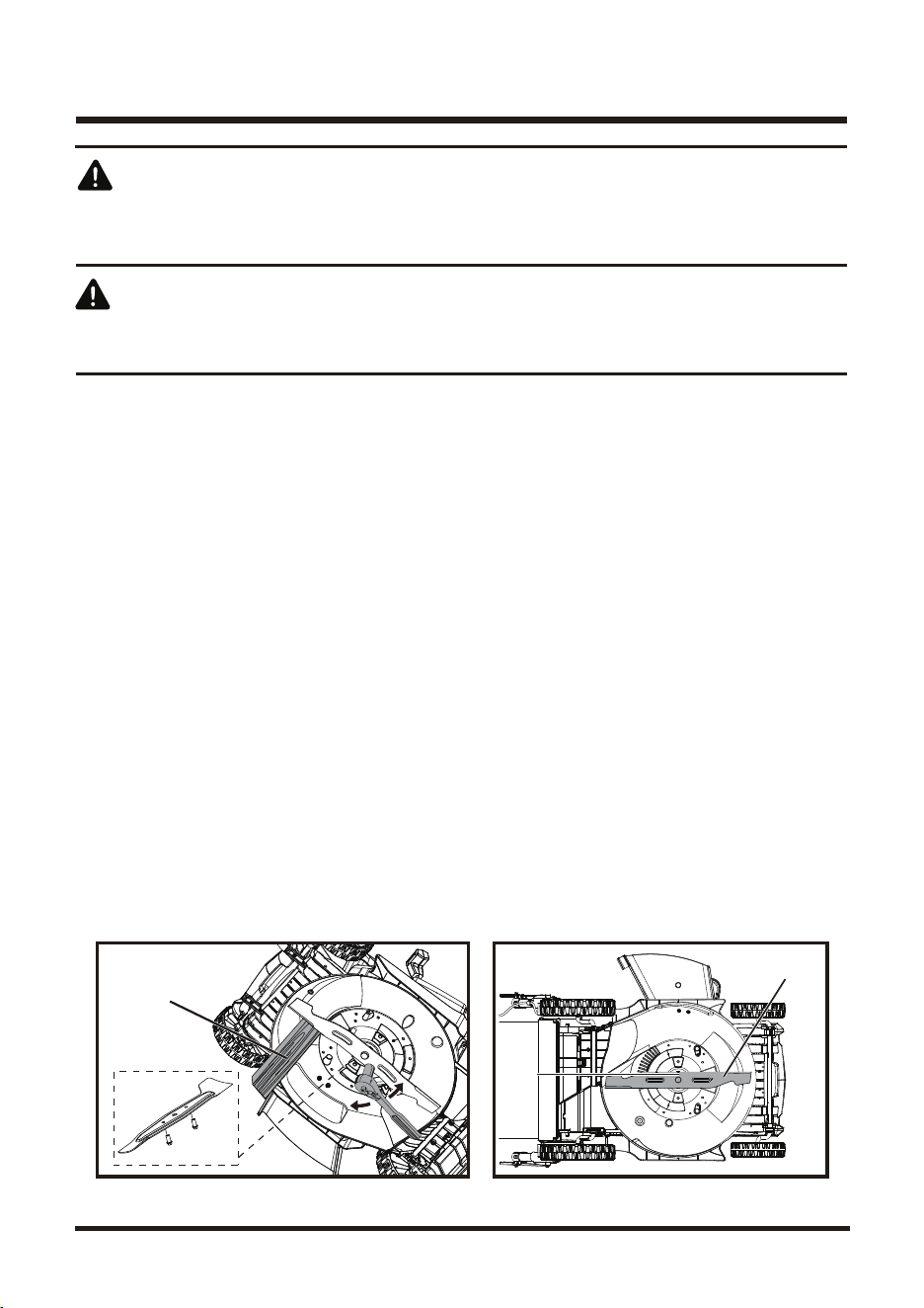
REPLACING THE MOWER BLADE (See Figs. 24-25)
NOTE: Unplug mower from power supply before performing any maintenance!
NOTE: Only use identical replacement blades. LawnMaster
®
mower blade replacement part #RMB1218E.
■ Stop the motor and allow the blade to come to a complete stop.
■ With blade stopped, disconnect the plug from power supply and store the mower in safe location.
■ Remove collection bag from mower if attached.
■ Slowly turn the mower onto its side.
■ Wedge a block of wood between the blade and the mower deck in order to prevent blade from
turning while the blade nut is being removed.
Before performing any maintenance, make sure the motor is stopped and the mower is disconnected
from the power supply. Failure to heed this warning could result in serious personal injury.
WARNING
Before performing any maintenance, make sure the mower is unplugged from the power supply.
Failure to heed this warning could result in serious personal injury.
WARNING
20
MAINTENANCE
25.giF24 .giF
BLADE
WOODEN BLOCK
BOLT
■ Loosen the blade nut using a wrench or socket (not provided).
■ Remove the blade nuts counterclockwise, then remove the blade.
■ Make certain the fan assembly is pushed completely against the motor shaft.
■ Place the new blade on the shaft against the fan assembly. Make sure it is installed with the
curved ends pointing up toward the mower deck and not down toward the ground.
■ Thread the blade nuts on the shaft and finger tighten.
to ensure the bolt is properly tightened.
■ Torque the blade nuts down using a torque wrench (not provided) to 25 N•m (221.5 pound-inches)
NOTE: Make certain all parts are replaced in the exact order in which they were removed.
21
When removing, inspect the blade carefully. If blade is bent or damaged, replace immediately with
a new blade. Failure to replace a bent or damaged blade could cause an accident resulting in
possible serious injury.
WARNING
MAINTENANCE
SHARPENING THE BLADE (See Fig. 26-27)
For best mowing performance, the mower blade must be kept sharp. A dull blade does not cut grass
evenly and overloads the motor. Under normal circumstances, sharpening the blade twice during
the mowing season is usually sufficient. However, if your lawn has sandy soil, more frequent
sharpening may be required.
■ Following the instructions in the Replacing Mower Blade section (p. 25), remove the mower blade.
DO NOT attempt to sharpen the blade while it is attached to the mower.
■ Using a fine-tooth file or sharpening stone, sharpen cutting edges on both ends of the blade,
removing equal amounts of material from both ends.
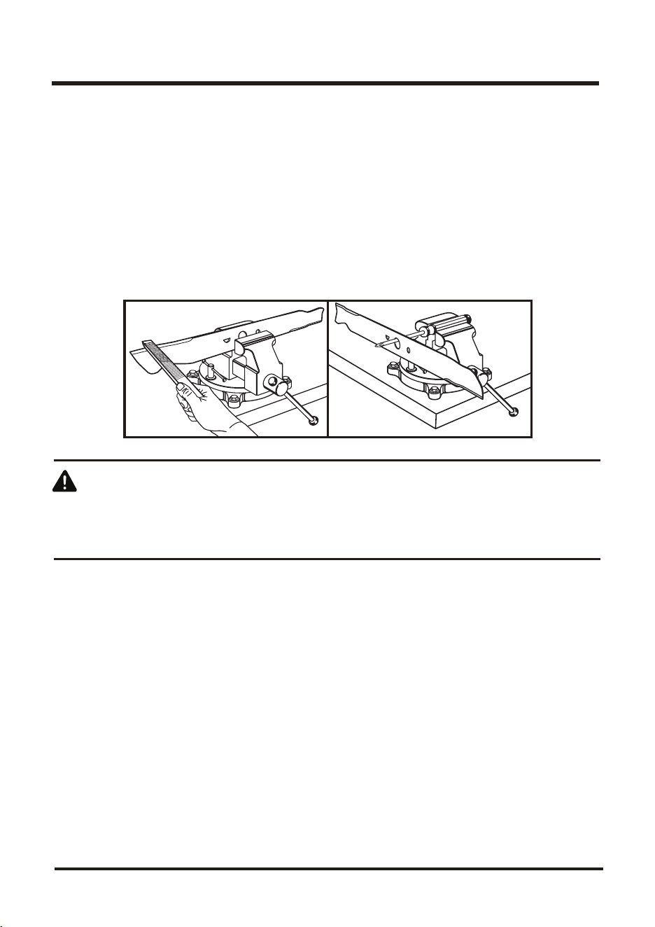
BALANCING THE BLADE (See Fig. 27)
When sharpening, care should be taken to keep the blade balanced. An unbalanced blade will cause
excessive vibration when the mower is running. This vibration will eventually cause damage to the
mower, especially the motor.
To check the blade balance:
■ Clamp a screwdriver horizontally in a vise as shown.
NOTE: If a vise is not available, a straight nail can also be used.
■ Place the center hole of blade on the screwdriver (or nail) shank.
■
If blade is balanced, it will remain in a horizontal position. If either end of the blade drops downward,
sharpen the heavy side until the blade is balanced.
Fig.27 Fig.26
22
MAINTENANCE
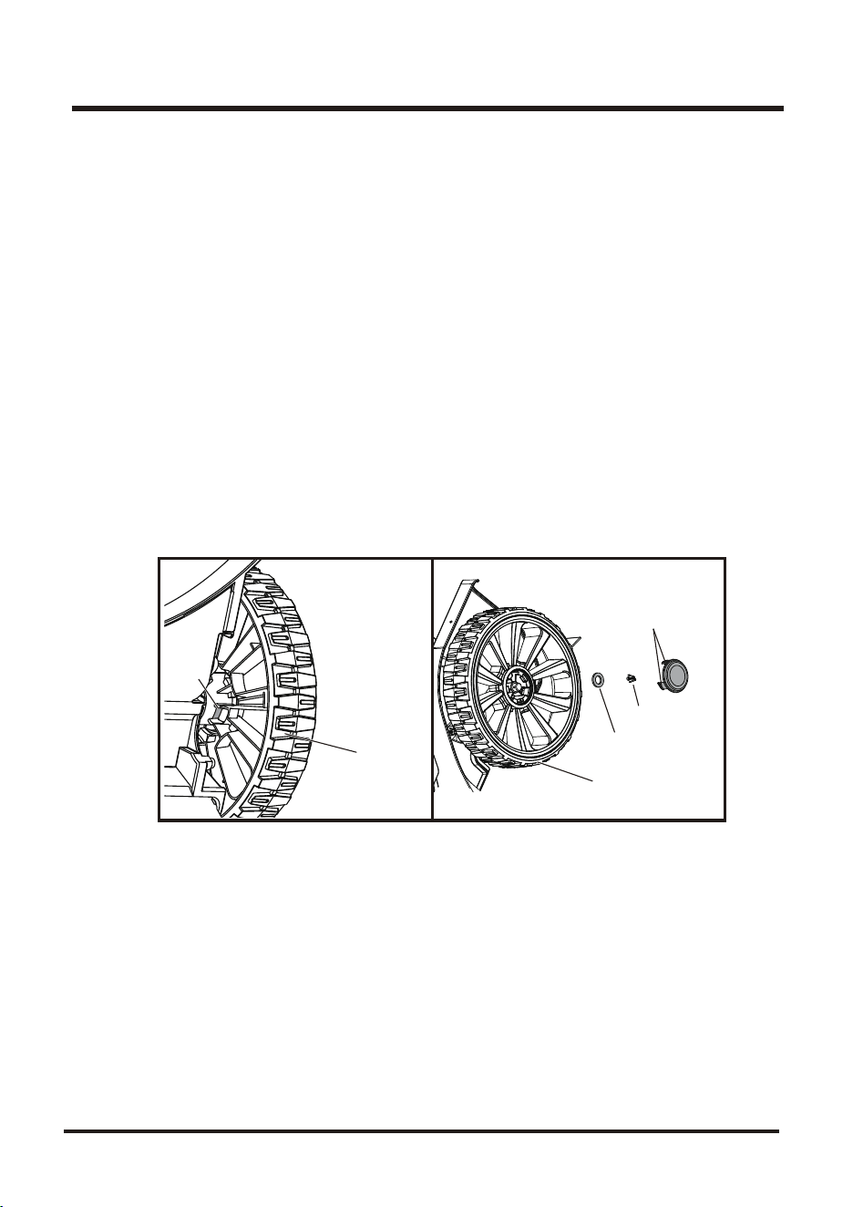
REPLACING WHEELS (See Fig. 28-29)
To replace a wheel:
NOTE: before replacing a rear wheel, set the mower at the highest position.
■ Disconnect the plug form power supply at first before replacing the wheel.
■ Turn the mower upright.
■ Push the inner hubcap tabs from inner side of the wheel, by using a flat head screwdriver or other
adequate tool.
■ When all inner hubcap tabs have been depressed, the hubcap should become free allowing
access to the axle.
■ Remove the cotter pin using a pair of pliers, and slide the washer off the axle.
■ Remove the wheel, replace with a new identical replacement wheel.
■ Reinstall the washer and press cotter pin back into place. Reinstall the inner hubcap. Make sure
all tabs are locked into place.
NOTE: Servicing or replacing requires extreme care, knowledge and skills, and we suggest it be
performed by a qualified service technician. You can return the product to your nearest SERVICE
CENTER for repairing or replacing. When servicing, use only identical replacement parts.
WHEEL
WHEEL
Tab
Tab
Fig. 28 Fig. 29
Cotter Pin
Washer
23
MAINTENANCE
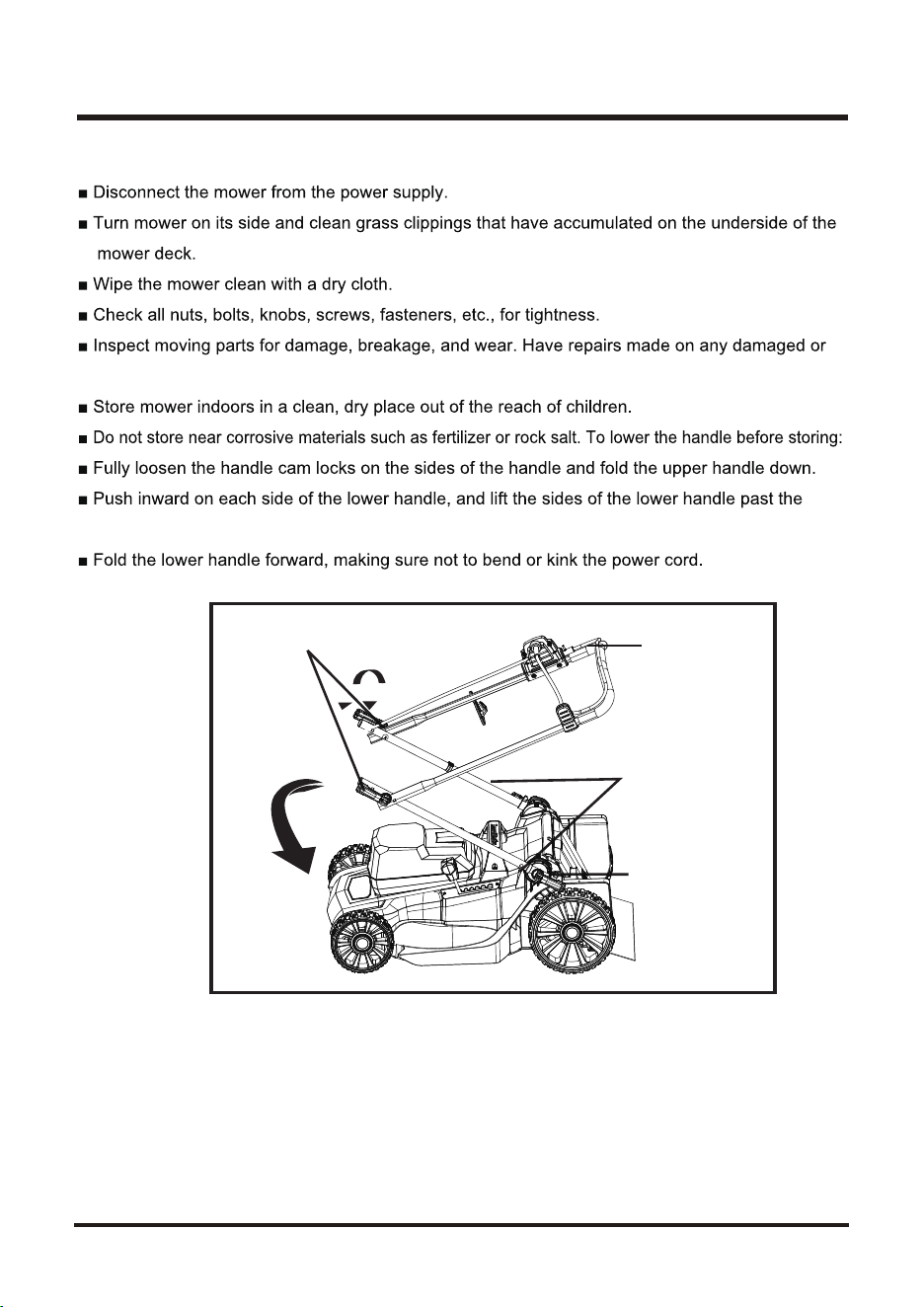
STORING THE MOWER (See Fig. 30)
missing parts.
edges of the handle mounting brackets.
HANDLE CAM LOCKS
UPPER
HANDLE
LOWER HANDLE
ASSEMBLY
Fig. 30
FIXED PLATE
24
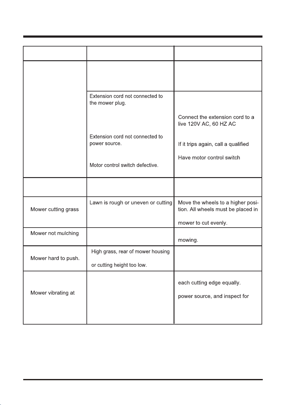
TROUBLESHOOTING
Problem Possible Cause Solution
Carriage bolts not seated properly.
Cam locks not tightened.
Adjust the height of the handle
and make sure the carriage bolts
are seated properly.
Tighten cam locks.
Tripped circuit breaker in the house.
Reconnect the cord and use the
cord retainer to keep the cord
close to the motor/blade control.
receptacle.
Reset house circuit breaker.
electrician.
replaced by an authorized
service center.
height not set properly.
the same cutting height for the
Handle not in position.
Mower fails to start.
circuit breaker in the house
tripped.
unevenly.
Wet grass clippings sticking to the
underside of the deck.
Wait until the grass dries before
properly.
and blade dragging in heavy grass,
Raise cutting height.
Blade is unbalanced.
Bent motor shaft.
Balance the blade by grinding
Stop the motor, disconnect the
damage. Have repaired made by
an authorized service center
before restarting.
higher speed
25
WARRANTY
under normal household use. If product is to be used for commercial, industrial or rental use, a 30
Warranty does not apply to defects due to direct or indirect abuse,
negligence, misuse, accidents, repairs or alterations and lack of maintenance. Please keep your
(866) 384-8432.
1. Any part that has become inoperative due to misuse, commercial use, abuse, neglect, accident,
improper maintenance, or alteration;
4. Routine maintenance items such as lubricants, blade sharpening;
SAVE YOUR RECEIPTS. THIS WARRANTY IS VOID WITHOUT THEM.
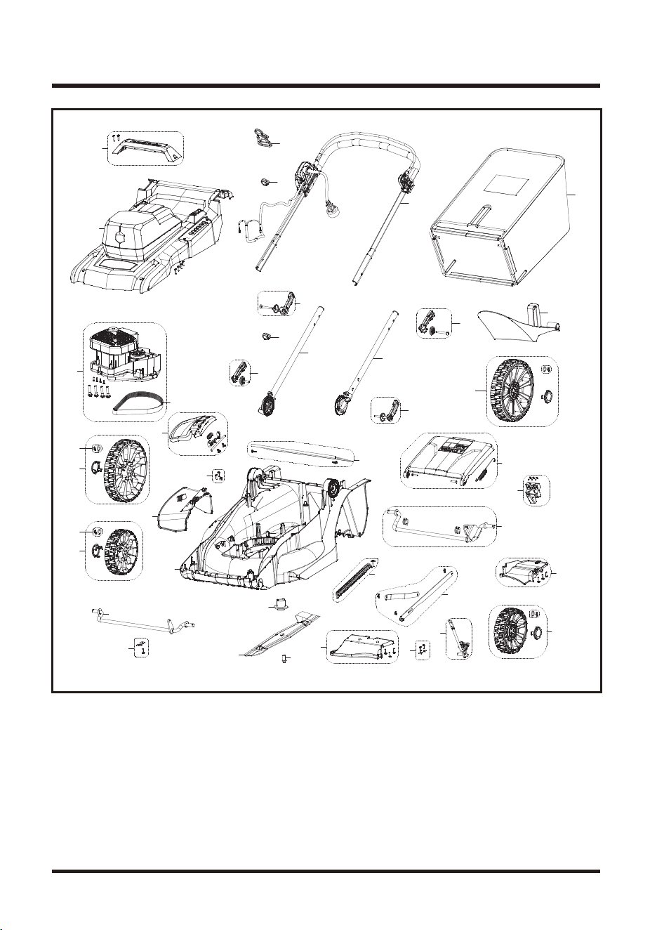
EXPLODED VIEW / PARTS LIST
26

27
EXPLODED VIEW / PARTS LIST
Key Number
1
2
3
3.1
4
5
6
7
7.1
8
9
10
11
12
13
14
15
16
17
18
19
20
21
22
23
24
25
26
27
28
29
30
31
32
33
1
1
1
1
1
1
1
2
4
1
2
1
1
1
1
1
1
1
1
1
1
1
1
1
1
1
2
1
1
2
1
1
2
1
1
111242101
111242102
111242103
111007103
111198110
111008129
111198111
111242104
111242105
111242106
111242107
111198116
111088115
111242108
111242109
111007114
111242110
111198119
111198120
111242112
111198118
111198122
111198124
111242113
111242114
111242115
111242116
111242117
111242118
111242119
111242120
111005128
111001111
111242121
111198130
Motor cover handle assembly
Motor cover assembly
Motor assembly
Drive belt
Side discharge door assembly
Cable clamp assembly
Side discharge chute
Wheel assembly (235mm)
Pin assembly
Deck assembly
Wheel assembly (170mm)
Front axle assembly
Wheel shaft clamp assembly
Locating ring
Blade
Bolt M10*20
Deck bottom protect plate assembly
Axle Bracket
Height adjustment assembly
spring assembly
Connection assembly
Deck cover plate
Rear axle assembly
Height adjustment knob assembly
Safety door assembly
Skin block assembly
Lower cam lock
Right lower handle assembly
Left lower handle assembly
Upper cam lock
Upper handle assembly with switch box
Cord retainer
Cable clips
Collection Bag Assembly
Mulch plug
Part Number
CLMFT6018A MANUAL PARTS LIST
Description Quantity

28
NOTES