1. SAFETY
1.1. GENERAL SAFETY
9 The user shall work in accordance with the instruction handbook.
9 Always lower, centre and use safety tyre holder before attempting to move trolley.
9 It is necessary that the operator can watch the lifting device and the load during all movements.
9 Only use the lifter trolley on firm, level, unobstructed surfaces which are capable of supporting the lifter trolley and wheel.
WARNING! It is not allowed to work under the raised load until it is secured by suitable means. If more than 400N of effort is generated in
lifting, the efforts shall be lowered by an additional person.
WARNING! Make sure there are safe working procedures in place when removing wheel in high wind/ bad weather conditions.
8 DO NOT use wheel removal/lifter trolley on ships.
8 DO NOT use with tandem and duplex wheel and tyre combinations.
8 DO NOT use with tyres that are wider than 12” (304mm).
8 DO NOT use the lifter trolley to lift persons.
8 DO NOT overload the lifter trolley - maximum capacity is 50kg.
8 DO NOT ride on the lifter trolley.
8 DO NOT have direct contact between lifter trolley and with foodstuffs.
8 DO NOT use on tarmacadam. The lifter trolley must only be used on a concrete level surface with no obstructions.
9 WD50QLS is fitted with locking castors, these are for use at the operator’s discretion and when the trolley is left unattended.
9 Replace or repair damaged parts. Use only recommended parts. Unauthorised parts may be dangerous and will invalidate the warranty.
9 Use a qualified person to lubricate and maintain the lifter trolley.
WARNING! Failure to comply with these instructions may result in loss of load, damage to trolley or other property and/or personal
injury.
WARNING! The warnings, cautions and instructions discussed in this manual cannot cover all possible conditions and situations that
may occur. It must be understood that common sense and caution are factors which cannot be built into this product, but must be
applied by the operator.
WARNING! The Lifter trolley is only designed to lift wheels. Lifting other items can seriously danger life and property.
1.2. HANDLING OF LOADS
8 DO NOT lift or lower a load with the lifter trolley until the operator and all other personnel are clear of the load.
8 DO NOT lift a load until it is secured using the safety chain.
8 DO NOT leave a suspended load unattended.
1.3. PROTECTIVE MEASURES
1.3.1. Make sure protective measures are in place, always use protective footwear, and protective gloves.
1.4. LIMITATIONS OF OPERATION IN SEVERE CONDITIONS
1.4.1. Ensure that lifting trolley is not used outdoors in bad weather, and high winds.
WARNING! The operator shall be provided with all necessary information about training and about pumping and translating forces.
1.5. PERMISSIBLE ENVIRONMENTAL CONDITIONS (Temp/Moisture/Vibration)
1.5.1. Use lifter trolley in a Dry, clean and stable environment, not on a uneven, damaged oor.
1.6. WARNING LABELS NEED TO STAY AS ORIGINALLY SUPPLIED
1.6.1. Contact Sealey Service for replacement Warning labels should they get damaged or destroyed.
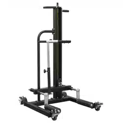
2. INTRODUCTION
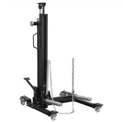
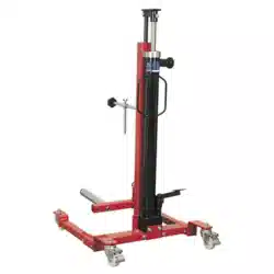
Lifting mechanism reaches height up to 1078mm. Raised using an impact gun reducing time and effort needed to raise the roller arms
to the wheel. Solid steel construction, with friction mounted roller arms. Front and lockable rear castors for easy manoeuvrability and
stability. Supplied with safety bar to prevent wheel from tipping forward.
3. SPECIFICATION
WHEEL REMOVAL/LIFTER TROLLEY 50KG QUICK
LIFT
Thank you for purchasing a Sealey product. Manufactured to a high standard, this product will, if used according to these instructions,
and properly maintained, give you years of trouble free performance.
IMPORTANT: PLEASE READ THESE INSTRUCTIONS CAREFULLY. NOTE THE SAFE OPERATIONAL REQUIREMENTS, WARNINGS & CAUTIONS. USE
THE PRODUCT CORRECTLY AND WITH CARE FOR THE PURPOSE FOR WHICH IT IS INTENDED. FAILURE TO DO SO MAY CAUSE DAMAGE AND/OR
PERSONAL INJURY AND WILL INVALIDATE THE WARRANTY. KEEP THESE INSTRUCTIONS SAFE FOR FUTURE USE.
Refer to
instruction
manual
Wear
protective
gloves
Wear
protective
footwear
Original Language Version
© Jack Sealey Limited
WD50QLS Issue 2 30/01/25
Model No: WD50QLS
Applicable Standards: EN ISO 12100:2010
EN 1494:2000+A1:2008
Maximum Lifting Capacity: 50kg
Maximum Lifting Height: 1078mm
Minimum Lifting Height: 93mm
Nett Weight: 48kg
Roller Length: 240mm
Width Between Rollers: 500mm
Maximum width of tyre 304mm
MODEL NO: WD50QLS
4. ASSEMBLY
Activate the locks on the locking castor wheels so the lifter will not
move during the assembly.
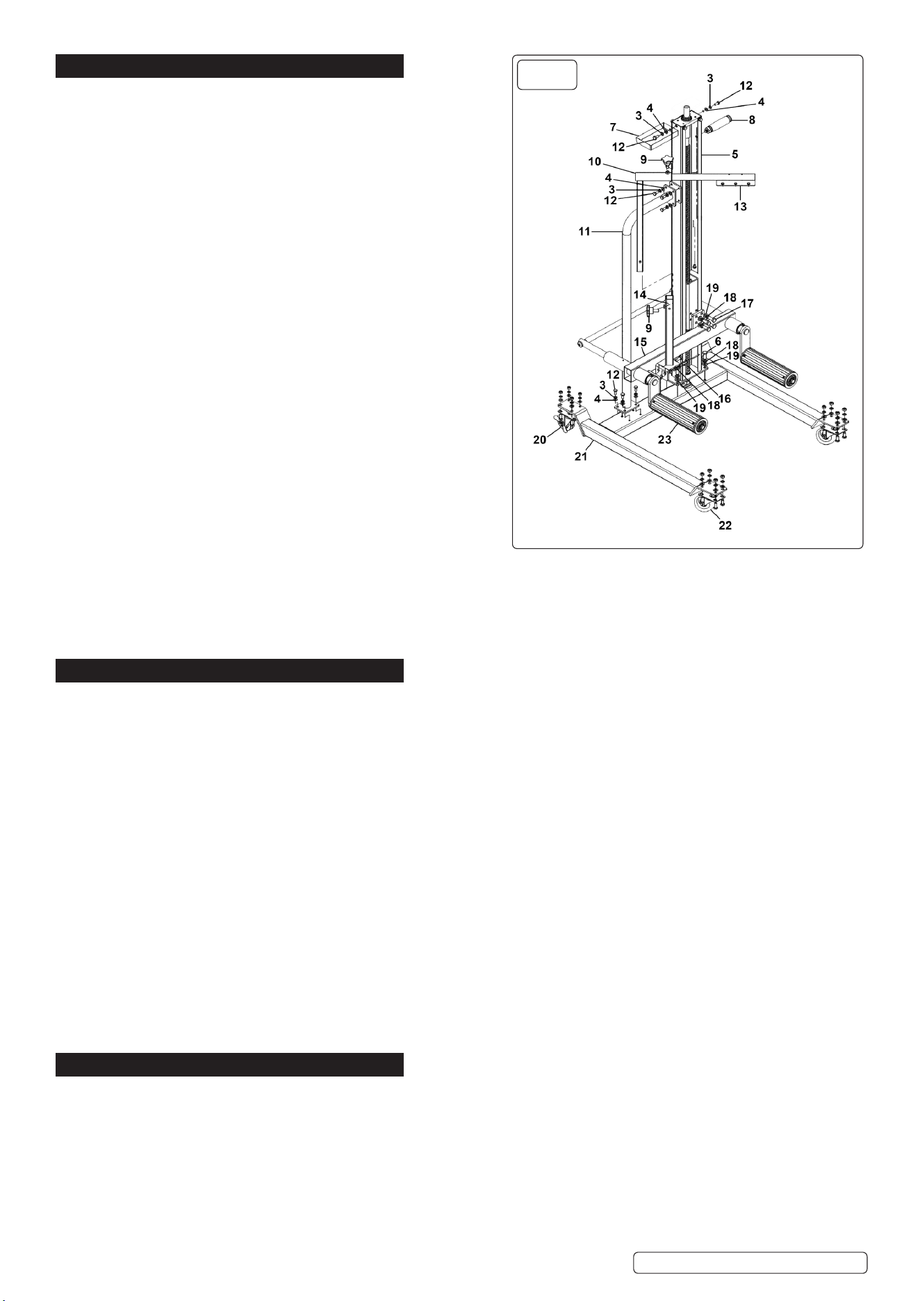
PROCEDURES. NOTE: Numbers in diagrams correspond to the item
numbers on the attached parts diagram.
Use correct fixing components as listed on the parts diagram.
4.1. ASSEMBLING THE CASTOR BASE
4.1.1. Referring to fig.1, take Frame Base (21) and attach the non-locking
Fixed Castor wheels (22) to the front of Frame Base (21).
4.1.2. Attach a Locking castor wheels (w/Brake) (20) to the Frame Base
(21) .
4.1.3. MAIN UPRIGHT ASSEMBLY
4.1.4. The main Upright Assembly (5) can be fixed to the Frame Base (21).
4.1.5. The lifter can be activated directly from the top of the Main Upright
Assembly (5). Do Not tighten up hardware at this time.
4.2. ASSEMBLING THE ROLLER SUPPORT
4.2.1. The Lift Arm Assembly (15) attaches to the lift assembly.
4.2.2. Attach the Roller Assembly (23) to the Lift Arm assembly (15).
4.3. ASSEMBLING THE TYRE HOLDER
4.3.1. Referring to fig.1 attach Socket for Tyre Holder (14) as indicated in
the parts list. Slide Tyre Holder Upright into Socket for tyre Holder
(14). Add the Knob, Plastic (9), to the Knurled to the Socket for Tyre
Holder (14). Add the Knob, Plastic (9) to the Tyre Holder Upright (10).
4.3.2. STEERING HANDLE ASSEMBLY
4.3.3. Referring to fig.1 attach one end of Main Steering Handle (11) to the
Frame Base (21) and the other end to Main Upright Assembly (5).
4.3.4. Attach Tool Tray (7) to Upright Assembly (5).
4.4. ACCESSORIES
4.4.1. Attach the Side Handle (8).
4.4.2. Tighten all hardware up.
4.5. CENTRE OF GRAVITY
4.5.1. The centre of gravity is a theoretical point where the total weight of an object is considered to be concentrated. For a uniform object,
this point lies at its geometrical centre. However, the centre of gravity may not necessarily be at the geometrical centre for irregularly
shaped or unevenly loaded objects, such as a lifter trolley carrying a load.
When transporting or moving the unit, be aware that it maybe unstable due to its conguration and centre of gravity. Ensure it is rmly
held if being carried by a fork lift truck.
5. OPERATION
5.1. PUTTING INTO SERVICE/MANUAL CONTROLS
5.2. LIFTING - Raising and lowering of the lifter is accomplished by engaging the ½” drive tool with the ½” drive socket at the top of the (#5)
main upright assembly. The drive tool can be a ½” air impact gun or ½” rechargeable impact gun.
5.3. Raise the vehicle to the desired work height and ensure the vehicle is secured.
5.4. Make sure the wheel/tyre combination to be removed will clear the vehicle lift and remove the lug nuts.
5.5. Push the lifter in towards the wheel/tyre combination and raise the (#15) lift arm assembly so the lift arms straddle the tyre. It may be
necessary to extend the telescopic portion of the (#15) lift arm assembly so the side wall of the tyre comes in contact with the rear of the
lift arm offset. Raise the (#15) lift arm assembly so its individual lift arm rollers make contact with the tyre.
5.6. SECURING THE WHEEL
5.7. Secure the wheel/tyre combination to the lift arms with the (#13) tyre hold. This can be accomplished by loosening the (#9) knobs on the
(#14) socket for tyre hold and (#10) tyre hold upright. Loosening the knobs will enable the (#10) tyre hold upright to extend to a height
necessary for the (#13) tyre hold to clear the tyre and then extend the (#13) tyre hold so it is positioned and makes contact with the center
of the tyre. Once adjustments are made, tighten the knob on the (#10) tyre hold upright. Now push down on the (#13) tyre hold while
tightening the knob on the (#14) socket for tyre hold.
5.8. Retract the telescopic portion of the (#15) lift arm assembly if it has been extended and slowly pull the lifter away from the wheel drum
making sure the wheel/tyre combination clear the drum and the vehicle lift.
5.9. LOWERING - Fit 1/2” square drive socket into the top of the main upright. Turn anti-clockwise for controlled lowering of the roller
assembly.
5.10. TRANSPORTATION - Before moving a laden trolley ensure that the wheel is centred on the rollers, and the safety tyre holder has been
attached over the wheel. Ensure that the roller assembly is fully lowered before moving a wheel.
5.11. WORK SPACE REQUIRED
9 Always ensure adequate space is present when using the lifter trolley. Ensure clear path to destination.
6. MAINTENANCE
6.1. PREVENTATIVE MAINTENANCE TO BE OBSERVED
Always keep unloaded whilst not in use.
Daily: Check for damage.
Monthly: Oil moving parts.
Check for abnormal wear and tear.
9 Always ensure adequate space around the lifter trolley when conducting maintenance.
WARNING! The need to check the state of the marking and that the marking remain as the initial one.
6.2. NECESSARY SAFETY CHECKS
• Check all metal parts for operation.
• Check castor wheels and brakes.
Original Language Version
© Jack Sealey Limited
WD50QLS Issue 2 30/01/25
25
FIG.1

6.3. ADJUSTMENTS AND MAINTENANCE OPERATIONS TO THE PRODUCT
6.3.1. Before each use, visual inspection shall be made before each use of the lifter trolley checking for cracks, cracked welds and/or
damaged parts, check the tightness of fasteners. Any lifter trolley that appears to be damaged in any way shall be removed from service
immediately.
6.3.2. Lifters shall be maintained and repaired in accordance with the manufacturer’s instructions, such maintenance and repair shall be carried
out by qualified persons.
6.3.3. No modifications shall be carried out which adversely affect the compliance of the jack with this standard.
6.4. TRANSPORT AND HANDLING
6.4.1. During transport to the worksite and whilst in store at the worksite, the equipment should be protected from exposure to any conditions
which may affect its ability to operate safely. In particular, it should be protected from exposure to:
• Water/sea water;
• Temperatures higher than can be comfortably tolerated by the hand.
• Temperatures below freezing point.
• Solvents.
• Corrosive chemicals or fumes.
• Grit, sand and wind-blown dust.
8 DO NOT use if damaged.
6.5. REPAIR
6.5.1. For any repair contact the place of purchase, or call your Sealey Service Centre.
6.6. STORAGE
6.6.1. Store in a dry safe place out of the reach of children.
6.7. SPARES
6.7.1. Refer to the attached spare parts list.
6.8. DECOMMISSIONING/ LIFE TIME OF THE PRODUCT/ DISPOSAL
6.8.1. Through years of normal wear, the unit will eventually become unserviceable. When this happens ensure that it is disposed of in
accordance with local authority regulations.
6.9. ACCIDENT OR BREAKDOWN
6.9.1. In the event of an accident or breakdown stop raising or lowering, move to a safe distance risk assess the problem.
6.9.2. Inspect and either discontinue to use, or if safe to do so continue.
6.10. CLEANING
6.10.1. Keep the lifter trolley in a clean and dry environment. DO NOT store it in, or expose it to, a damp or wet environment.
Original Language Version
© Jack Sealey Limited
WD50QLS Issue 2 30/01/25
Sealey Group, Kempson Way, Suffolk Business Park, Bury St Edmunds, Suffolk. IP32 7AR
01284 757500 sales@sealey.co.uk www.sealey.co.uk
Note: It is our policy to continually improve products and as such we reserve the right to alter data, specifications and component parts without prior notice.
Important: No Liability is accepted for incorrect use of this product.
Warranty: Guarantee is 36 months from purchase date, proof of which is required for any claim.
ENVIRONMENT PROTECTION
Recycle unwanted materials instead of disposing of them as waste. All tools, accessories and packaging should be sorted,
taken to a recycling centre and disposed of in a manner which is compatible with the environment. When the product
becomes completely unserviceable and requires disposal, drain any fluids (if applicable) into approved containers and
dispose of the product and fluids according to local regulations.