1. SAFETY
1.1. GENERAL SAFETY
9 The user shall work in accordance with the instruction handbook.
9 Always lower, centre and use safety chain before attempting to move trolley.
9 It is necessary that the operator can watch the lifting device and the load during all movements.
9 Only use the lifter trolley on firm, level, unobstructed surfaces which are capable of supporting the lifter trolley and wheel.
WARNING! It is not allowed to work under the raised load until it is secured by suitable means.
WARNING! The operator shall be provided with all necessary information about training and about pumping and translating forces.
WARNING! If more than 400N of effort is generated in lifting, the efforts shall be lowered by an additional person.
WARNING! Make sure there are safe working procedures in place when removing wheel in high wind/ bad weather conditions.
8 DO NOT use wheel removal/lifter trolley on sea ships.
8 DO NOT use the lifter trolley to lift persons.
8 DO NOT overload the lifter trolley - maximum capacity is 100kg.
8 DO NOT ride on the lifter trolley.
8 DO NOT have direct contact between lifter trolley and with foodstuffs.
8 DO NOT use on tarmacadam. The lifter trolley must only be used on a concrete surface.
9 WD100S is fitted with locking castors, these are for use at the operator’s discretion and when the trolley is left unattended.
9 Replace or repair damaged parts. Use only recommended parts. Unauthorised parts may be dangerous and will invalidate the warranty.
9 Use a qualified person to lubricate and maintain the lifter trolley. DO NOT use brake fluid to top up hydraulic unit. Use Sealey hydraulic oil
only.
WARNING! Failure to comply with these instructions may result in loss of load, damage to trolley or other property and/or personal injury.
WARNING! The warnings, cautions and instructions discussed in this manual cannot cover all possible conditions and situations that
may occur. It must be understood that common sense and caution are factors which cannot be built into this product, but must be
applied by the operator.
WARNING! The Lifter trolley is only designed to lift wheels. Lifting other items can seriously danger life and property.
1.2. HANDLING OF LOADS
8 DO NOT lift or lower a load with the lifter trolley until the operator and all other personnel are clear of the load.
8 DO NOT lift a load until it is secured using the safety chain.
8 DO NOT leave a suspended load unattended.
1.3. PROTECTIVE MEASURES
1.3.1. Make sure protective measures are in place, always use protective footware, and protective gloves.
1.4. LIMITATIONS OF OPERATION IN SEVERE CONDITIONS
1.4.1. Ensure that lifting trolley is not used outdoors in bad weather, and high winds.
1.5. PERMISSIBLE ENVIRONMENTAL CONDITIONS (Temp/Moisture/Vibration)
1.5.1. Use lifter trolley in a Dry, clean and stable environment, not on a uneven, damaged oor.
1.6. WARNING LABELS
1.6.1. Contact Sealey Service for replacement Warning labels should they get damaged or destroyed.
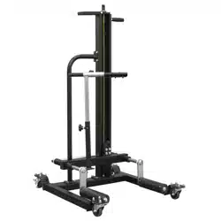
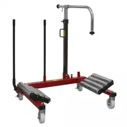
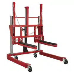
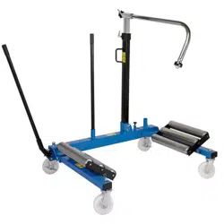
2. INTRODUCTION
Hydraulic mechanism reaches height up to 925mm. Two speed hydraulic unit reduces the time and effort needed to raise arms to
contact point. Solid steel construction, with friction mounted roller arms. Front and rear castors for easy manoeuvrability. For use on
multiple types of wheel, with 280-340mm between rollers. Supplied with safety bar to prevent wheel from tipping forward.
3. SPECIFICATION
WHEEL REMOVAL/LIFTER TROLLEY 100KG WITH
QUICK LIFT
Thank you for purchasing a Sealey product. Manufactured to a high standard, this product will, if used according to these instructions,
and properly maintained, give you years of trouble free performance.
IMPORTANT: PLEASE READ THESE INSTRUCTIONS CAREFULLY. NOTE THE SAFE OPERATIONAL REQUIREMENTS, WARNINGS & CAUTIONS. USE
THE PRODUCT CORRECTLY AND WITH CARE FOR THE PURPOSE FOR WHICH IT IS INTENDED. FAILURE TO DO SO MAY CAUSE DAMAGE AND/OR
PERSONAL INJURY AND WILL INVALIDATE THE WARRANTY. KEEP THESE INSTRUCTIONS SAFE FOR FUTURE USE.
Refer to
instruction
manual
Wear
protective
gloves
Wear
protective
footwear
Original Language Version
© Jack Sealey Limited
WD100S Issue 1 05/12/24
Model No: WD100S
Applicable Standards: EN ISO 12100:2010
EN 1494:2000+A1:2008
Maximum Lifting Capacity: 100kg
Maximum Lifting Height: 925mm
Minimum Lifting Height: 110mm
Nett Weight: 55kg
Roller Length: 270mm
Width Between Rollers: 280-340mm
MODEL NO: WD100S
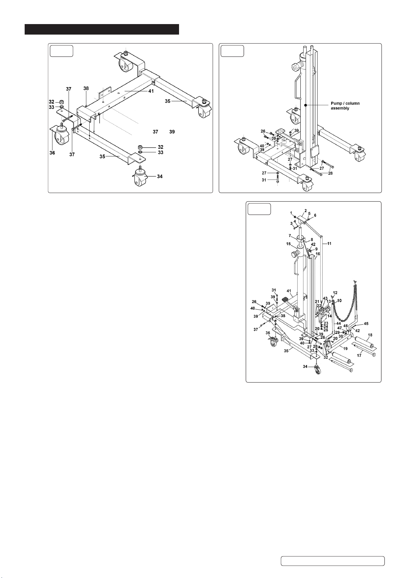
4. ASSEMBLY
FIG.1 FIG.2
NOTE: Numbers in diagrams correspond to the item numbers on the
attached parts diagram.
4.1. ASSEMBLING THE CASTOR BASE
4.1.1. Referring to fig.1, take one wheel beam (35) and attach a non-locking castor
(34) to the short wheel mounting plate using a spring washer M12 Zinc (33)
and Steel Nut M12 Zinc (32).
4.1.2. Attach a Swivel castor (w/Brake) (75x9x32x10) (36) to the long wheel
mounting plate using a locking washer (33) and nut (32). Attach the castors to
the other wheel beam (35).
4.1.3. Take the supporting beam (41) and mount a wheel beam at either end of it
as shown below. Drop the ‘U’ channels at either end of the supporting beam
down over each wheel beam. Align the holes in the wheel beams with the
holes in the supporting beam and insert two Hex Head Bolts M8 x 60mm (37)
at either side. Retain the four bolts by attaching four Steel Nuts M8 Zinc (6).
Assembling the pump/column to the castor base.
4.1.4. The Hydraulic Unit (15) and column unit is fixed to the supporting beam using
three pairs of fixings, two pairs in the horizontal plane and one pair in the
vertical plane.
4.1.5. Referring to fig.2, take the pre-assembled pump and column unit and slide
it onto the Main Upright (16), and up against the vertical plate welded to the
support beam. Align the holes in the pump block with the holes in the vertical
plate. Slide a Spring Washer M10 Zinc (39) onto each Hex Head Set Screw
M10 x 20 zinc (26) and insert the bolts through the plate and screw them
finger tight into the pump block.
4.1.6. Slide a washer onto each Socket Cap Bolt M10 x 110 (28) and insert the bolts
horizontally through the column bracket and all the way through the main
support beam. Secure the bolts finger tight only at this stage using two Spring
Washers M10 Zinc (39) and two Steel Nuts M10 Zinc (25).
4.1.7. Slide a washer onto each Socket Cap Bolts M10 x 65 (31) and insert the bolts vertically from underneath, through the corners of the Main
Upright (16) and all the way through the main support beam. Secure the bolts on the top surface of the beam using two Spring Washers
M10 Zinc (39) and two nuts.
4.1.8. Now progressively tighten all three pairs of fixings checking that the pump/column remains vertical.
4.2. ASSEMBLING THE ROLLER SUPPORT
4.2.1. Referring to fig.3, take the roller support assembly and bolt it to the angled plate at the base of the column using four Socket Cap Bolts M8
x 16mm Black (20).
4.3. ASSEMBLING THE BRIDGE JOINT
4.3.1. Referring to fig.3, take the Bridge Joint (2) and push it onto the end of the hydraulic ram so that channel walls lie either side of the lifting
rod.
4.3.2. Slide the Flat Washer M8 Zinc (4) onto the Hex Bolt M8 x 40 (3) and insert the bolt through the channel and through the lifting rod. Secure
the bolt with a Spring Washer M8 Zinc (5) and Steel Nut M8 Zinc (6). Insert the Adjusting Thread Bolt M6 x 16 (1) into the collar of the
bridge joint and tighten it.
4.4. ASSEMBLING THE GUIDE ROLLER
4.4.1. Referring to fig.3, attach Pulling Rod (11) to Side Block (43) using Flat Washer M10 Zinc, Flat Washer M10 Zinc, and Steel Nut M10 Zinc.
Insert the Guide Roller Pin (13) through the Side Block (43) and guide roller (14). Attach Nylon Plate (22) using Phillips Machine Screws
M5 x 10 Black. Once assembly is complete, slide into Main Upright (16). Attach Bridge Joint (2) to Pulling Rod (11) using Hex Head Bolt
M8 x 40 (3), Flat Washer M8 zinc (4), Spring Washer M8 Zinc (5), and Steel Nut M8 Zinc (6). Attach Lifting Beam (19) to Side Block
assembly (43).
Original Language Version
© Jack Sealey Limited
WD100S Issue 1 05/12/24
6
25
FIG.3
4.5. ATTACHING STOP LEVERS AND CHAIN
4.5.1. Referring to fig.3, Fit the two Stop Levers (44) into the Lifting Beam (19) using
Hex Head Bolts M6 x 35 (45), Flat Washers M6 Zinc (42), Spring Washer M6
Zinc (46), and Steel Nuts M6 Zinc (47). Attach Chain (10), using Wing Bolts
M8 x 12 (12).
4.6. CENTRE OF GRAVITY
4.6.1. The centre of gravity is a theoretical point where the total weight of an object
is considered to be concentrated. For a uniform object, this point lies at its
geometrical centre. However, the centre of gravity may not necessarily be
at the geometrical centre for irregularly shaped or unevenly loaded objects,
such as a lifter trolley carrying a load.
When transporting or moving the unit, be aware that it may unstable due to
its conguration and centre of gravity. Ensure it is rmly held if being carried
by a fork lift truck.
5. OPERATION
5.1. PUTTING INTO SERVICE
5.1.1. Remove the transit plug at the back of the hydraulic unit between the handles
and replace it with the vent valve supplied. See fig.4.
5.1.2. Set the position of the right hand roller to suit the size of wheel to be removed
/ installed (2 positions available). See fig.3.
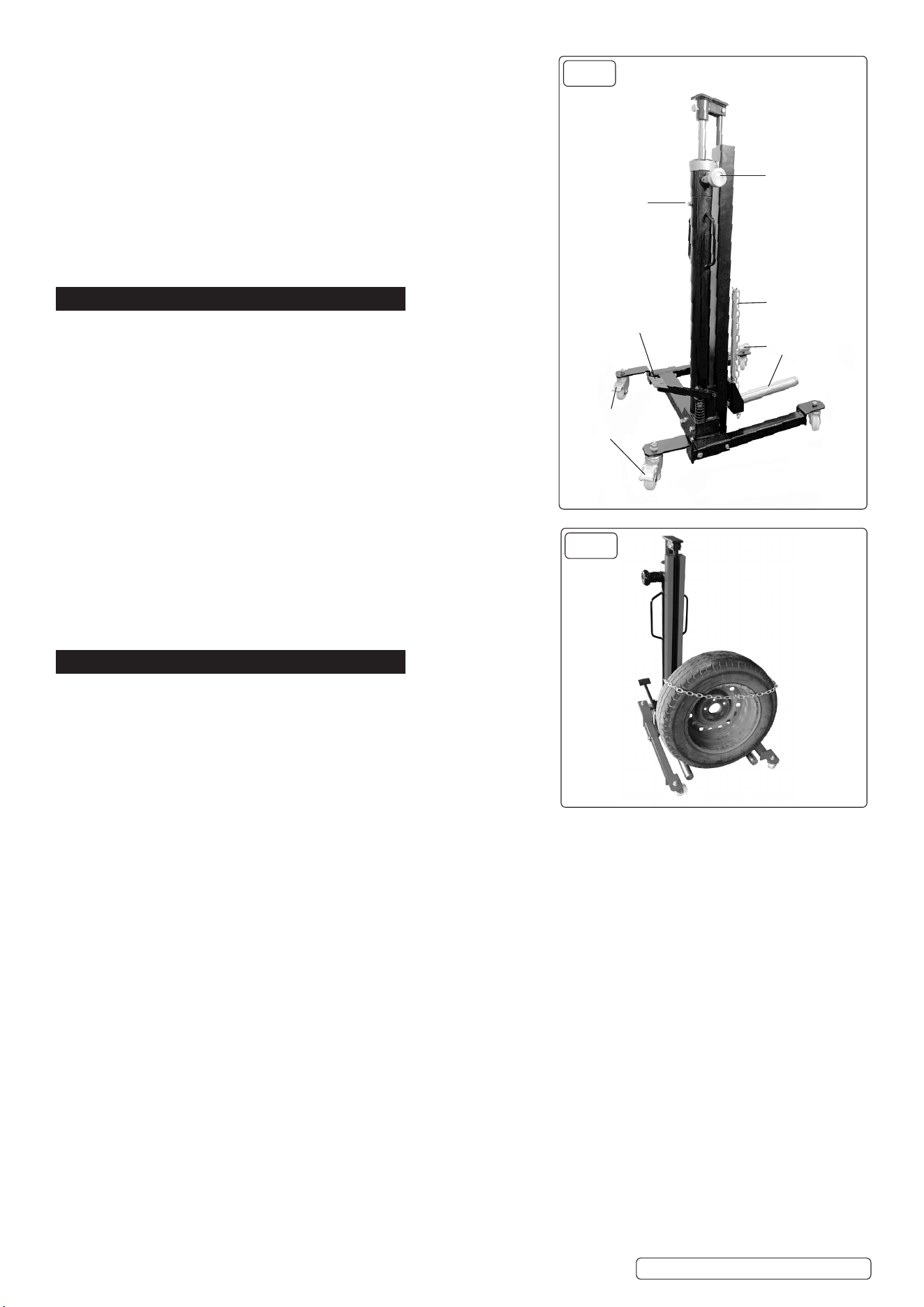
5.2. LIFTING - Raise the roller assembly by pumping the foot pedal up and down
through its full stroke until it reaches the correct height. Centre the trolley
around the wheel, as close in as possible. Attach the safety chain around the
wheel. See fig.5. When the wheel has been released from the vehicle and is
resting on the rollers move the trolley out from the vehicle.
5.3. LOWERING - The release valve is spring loaded shut. The speed of lowering
is dependent on how far you open the valve. Turn the valve anti-clockwise,
against spring load, for controlled lowering of the roller assembly.
5.4. TRANSPORTATION - Before moving a laden trolley ensure that the wheel is
centred on the rollers, and the safety chain has been attached over the wheel.
Ensure that the roller assembly is fully lowered before moving a wheel.
5.5. WORK SPACE REQUIRED
9 Always ensure adequate space is present when using the lifter trolley.
9 Always ensure adequate space around the lifter trolley when conducting
maintenance.
6. MAINTENANCE
6.1. PREVENTATIVE MAINTENANCE TO BE OBSERVED
Daily: Check for damage and oil leaks.
Monthly: Oil moving parts.
Check for abnormal wear and tear.
6.2. NECESSARY SAFETY CHECKS
• Check all metal parts for operation including foot pump and safety chain.
• Check castor wheels and brakes.
• Check operation of hydraulic system.
6.3. ADJUSTMENTS AND MAINTENANCE OPERATIONS TO THE PRODUCT
6.3.1. With roller assembly at lowest point, check hydraulic oil level by removing vent valve. Top up, or allow to drain, as necessary. Replace
vent valve.
6.3.2. Before each use, visual inspection shall be made before each use of the lifter trolley checking for cracks, cracked welds and/or
damaged parts, check the tightness of fasteners. Any lifter trolley that appears to be damaged in any way shall be removed from service
immediately.
6.4. BLEEDING
6.4.1. To maintain peak performance of the lifter trolley, periodically bleed the hydraulic system. Open the release valve by turning it anti-
clockwise, against spring pressure, and hold it open whilst pumping the foot pedal four or five times. Allow release valve to close.
6.4.2. The lifter trolley is finished in rugged powder coating, however it is advisable to keep the finish clean and free from excessive dust and dirt.
6.5. REFILLING HYDRAULIC FLUID/ CHARACTERISTICS
6.5.1. When refilling the hydraulic system, the characteristics of the hydraulic fluid used in the jack and the level of hydraulic fluid as it is given by
the manufacturer shall be observed. Unscrew bleed/fill bolt to add hydraulic fluid to the pump. Fill to level of bleed/fill bolt.
6.5.2. Jacks shall be maintained and repaired in accordance with the manufacturer’s instructions, such maintenance and repair shall be carried
out by qualified persons.
6.5.3. No modifications shall be carried out which adversely affect the compliance of the jack with this standard.
6.6. TRANSPORT AND HANDLING
6.6.1. During transport to the worksite and whilst in store at the worksite, the equipment should be protected from exposure to any conditions
which may affect its ability to operate safely. In particular, it should be protected from exposure to:
• Water/sea water;
• Temperatures higher than can be comfortably tolerated by the hand.
• Temperatures below freezing point.
• Solvents.
• Corrosive chemicals or fumes.
• Grit, sand and wind-blown dust.
8 DO NOT use if damaged.
Original Language Version
© Jack Sealey Limited
WD100S Issue 1 05/12/24
Vent valve
Foot pedal
(pump)
Locking
castors
Rollers
Release
valve
Safety chain
FIG.4
FIG.5
Illustration only

6.7. REPAIR
6.7.1. For any repair contact the place of purchase, or call your Sealey Service Centre.
6.8. STORAGE
6.8.1. Store in a dry safe place out of the reach of children.
6.9. SPARES
6.9.1. Refer to the attached spare parts list.
6.10. DECOMMISSIONING/ LIFE TIME OF THE PRODUCT/ DISPOSAL
6.10.1. Through years of normal wear, the unit will eventually become unserviceable. When this happens ensure that it is disposed of in
accordance with local authority regulations.
6.11. HOW TO DISPOSE OF HYDRAULIC FLUID
• Collect the old hydraulic fluid and store it in a water-proof and leak-proof container. Appropriate storage prevents the fluid from spilling
and contaminating the soil.
• Your waste hydraulic fluid could be reclaimable and recyclable, but you don’t intend to reuse it at home. Instead of disposing of with your
general waste, consider disposing of it at a recycling facility in your region.
6.12. HYDRAULIC FLUID SPILLAGE OF HAZARDOUS SUBSTANCES
6.12.1. Refer to MSDS
WARNING! Possible emissions or leakage of hazardous substances.
6.12.2. One of the best ways to prevent spills is to implement a regular maintenance program.
1. Assessment and Safety Precautions:
Before diving into the clean up process, conducting a thorough assessment of the spill is essential to identify the extent of the
contamination and any potential hazards. We would recommend prioritising safety by wearing appropriate personal protective equipment
(PPE) and establishing a safety perimeter around the spill area.
2. Containment of the Spill:
Immediate containment is crucial to prevent the spread of hydraulic oil and minimise environmental impact.
Use absorbent materials like spill pads, booms, or socks to surround the spill area. These materials effectively contain the oil, preventing it
from spreading further.
3. Absorption and Removal:
Once the spill is contained, the next step is to absorb and remove the hydraulic oil. We would use absorbent pads or pillows specifically
designed for oil spills. These products are highly effective in soaking up the oil, and they can be easily disposed of in accordance with
local regulations.
4. Cleaning Surfaces:
Hydraulic oil spills often leave surfaces slippery and hazardous. Prompt cleaning reduces the risk of slips and falls, promoting a safer
working environment.
5. Disposal of Contaminated Materials:
Proper disposal of contaminated materials is a critical aspect of the clean up process. Contacting local environmental agencies can guide
the proper disposal methods for oil-contaminated materials.
6.13. HYDRAULIC FLUID/ FLAMMABLE SUBSTANCES
6.13.1. Refer to MSDS for safety information.
6.14. ACCIDENT OR BREAKDOWN
6.14.1. In the event of an accident or breakdown contact your Sealey Service Centre.
6.15. CLEANING
6.15.1. Keep the lifter trolley in a clean and dry environment. DO NOT store it in, or expose it to, a damp or wet environment.
7. TROUBLESHOOTING
7.1. Roller assembly does not reach full height - low oil level, check and fill with Sealey Model No. HJO500MLS. Bleed system as described in
6.5.1.
7.2. Pump ineffective - oil level too high, check and drain.
Sealey Group, Kempson Way, Suffolk Business Park, Bury St Edmunds, Suffolk. IP32 7AR
01284 757500 sales@sealey.co.uk www.sealey.co.uk
Note: It is our policy to continually improve products and as such we reserve the right to alter data, specifications and component parts without prior notice.
Important: No Liability is accepted for incorrect use of this product.
Warranty: Guarantee is 12 months from purchase date, proof of which is required for any claim.
ENVIRONMENT PROTECTION
Recycle unwanted materials instead of disposing of them as waste. All tools, accessories and packaging should be sorted,
taken to a recycling centre and disposed of in a manner which is compatible with the environment. When the product
becomes completely unserviceable and requires disposal, drain any fluids (if applicable) into approved containers and
dispose of the product and fluids according to local regulations.
Original Language Version
© Jack Sealey Limited
WD100S Issue 1 05/12/24