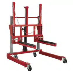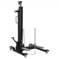
WHEEL REMOVAL TROLLEY 1500KG CAPACITY
MODEL NO: W1200T.V3
Thank you for purchasing a Sealey product. Manufactured to a high standard, this product will, if used according to these
instructions, and properly maintained, give you years of trouble free performance.
I
MPORTANT:
PLEASE READ THESE INSTRUCTIONS CAREFULLY. NOTE THE SAFE OPERATIONAL REQUIREMENTS, WARNINGS & CAUTIONS. USE
THE PRODUCT CORRECTLY AND WITH CARE FOR THE PURPOSE FOR WHICH IT IS INTENDED. FAILURE TO DO SO MAY CAUSE DAMAGE AND/OR
PERSONAL INJURY AND WILL INVALIDATE THE WARRANTY. KEEP THESE INSTRUCTIONS SAFE FOR FUTURE USE.
1. SAFETY
At least two people are required to assemble the trolley.
Ensure that the vehicle to be worked on is safely supported on axle stands.
Ensure that the trolley is in sound condition and good working order before use.
Keep trolley clean for best and safest performance.
Only use the trolley on rm, level, unobstructed surface which is capable of supporting the trolley and wheel.
Ensure there is no risk of pinching in between moving parts.
Ensure work area has adequate lighting.
Keep work area clean and tidy and free from unrelated materials.
Keep children and unauthorised persons away from the work area.
Ensure all non essential personnel keep a safe distance when the trolley is in use.
DO NOT overload the trolley - maximum capacity is 1500kg.
DO NOT allow untrained persons to operate the trolley.
DO NOT allow anyone to ride on the trolley.
DO NOT use on tarmacadam as it may sink under load.
DO NOT drive the unit over edges, rough surfaces etc. when loaded, as the whole unit may overturn.
DO NOT use trolley for purposes other than for which it is designed.
DO NOT operate the trolley when you are tired or under the in uence of alcohol, drugs or intoxicating medication.
DO NOT make any alterations to this device.
Always stand and operate the wheel trolley from behind Upright Tube (4), see g.1. Always move the Wheel Trolley using one
Handle (20) in the socket on the left hand side (as viewed in the g.1 position) and the other Handle (19) in the Socket above
Lowering Pedal (A), see g.2.
Push the wheel as far onto the rollers as possible.
Ensure that the load can not tilt whilst lowering or moving.
Lower the wheel and secure it with the wheel support before transporting.
It is of the greatest importance for safety that the wheel trolley is secured by the locking mechanism on the nearest hole before
manoeuvring the unit. If the lock is not used, the wheel trolley could come apart while carrying the load and the wheel could tip out.
Maintain correct balance and footing when moving trolley and ensure that the oor is not slippery.
Wear suitable clothing to avoid snagging. DO NOT wear loose jewellery and tie back long hair. A full range of personal safety
equipment is available from Sealey.
Replace or repair damaged parts. Use only recommended parts. Unauthorised parts may be dangerous and will invalidate the
warranty.
Use a competent person to lubricate and maintain the trolley. DO NOT use brake uid to top up hydraulic unit. Use approved
hydraulic oil only.
When not in use store trolley, fully lowered, in a safe, dry, childproof area.
WARNING! Failure to comply with these instructions may result in loss of load, damage to trolley or other property and/or personal
injury.
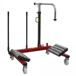
2. INTRODUCTION
Eight adjustable rollers (4 each side) allow for easy turning of large deep tread tyres. Extra large jacking handle and hydraulic foot
pedal allows for one man operation. Safety bar with composite guard goes around wheel to ensure stability during transportation.
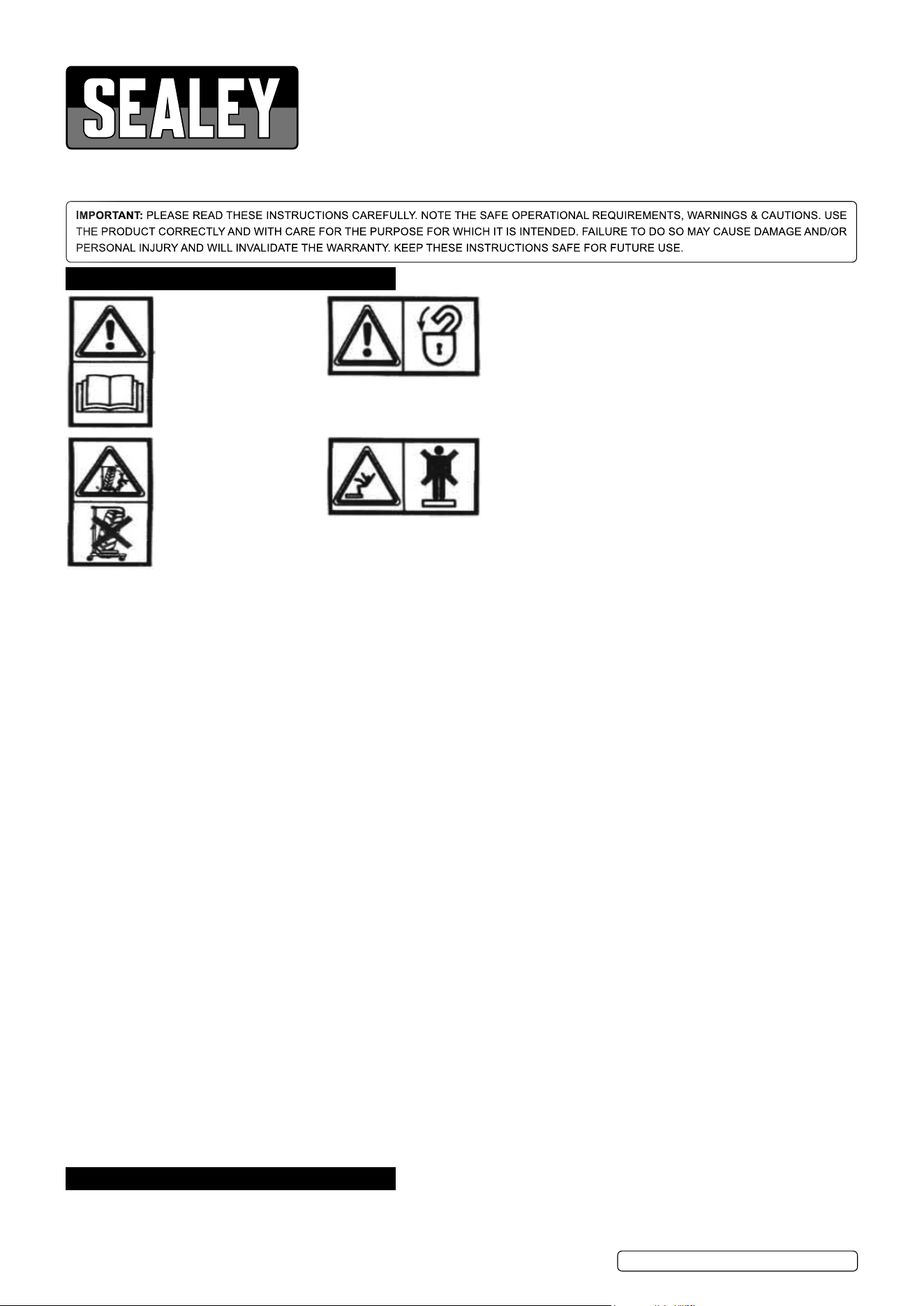
BEFORE OPERATION
Before operating, adjusting
or servicing the machine,
it is important that each
operator carefully reads the
operating instructions.
DURING OPERATION
Always use the locking
mechanism which locks
the lifting rollers in position
before manoeuvring the
loaded wheel changer.
DURING OPERATION
Danger from unsecured
load. The operator must
ensure that wheels to be
carried by the machine are
correctly loaded and
supported in accordance
with the operating
instructions.
DURING OPERATION
Potential slip/fall hazard.
Never stand or ride on the
wheel changer when
working with the machine.
Original Language Version
© Jack Sealey Limited
W1200T.V3 Issue 2 (H,5,F) 16/08/23
Locking mechanism allows rollers to be xed at eight pre-set positions. Mounted on two locking casters and two non-locking for
improved stability and easy manoeuvrability. Ideal for use on agricultural and commercial wheels and tyres.
3. SPECIFICATION
Model No: ..................................................... W1200T.V3
Maximum Lifting Capacity: .................................. 1500kg
Minimum Wheel Ø: ......................................... Ø1000mm
Maximum Wheel Ø: ........................................ Ø2000mm
Roller Length: ...................................................... 490mm
Minimum Lifting Height: ........................................ 0.1mm
Maximum Lifting Height: ...................................... 750mm
Overall Size (W x D x H): ........... 1300 x 1015 x 1500mm
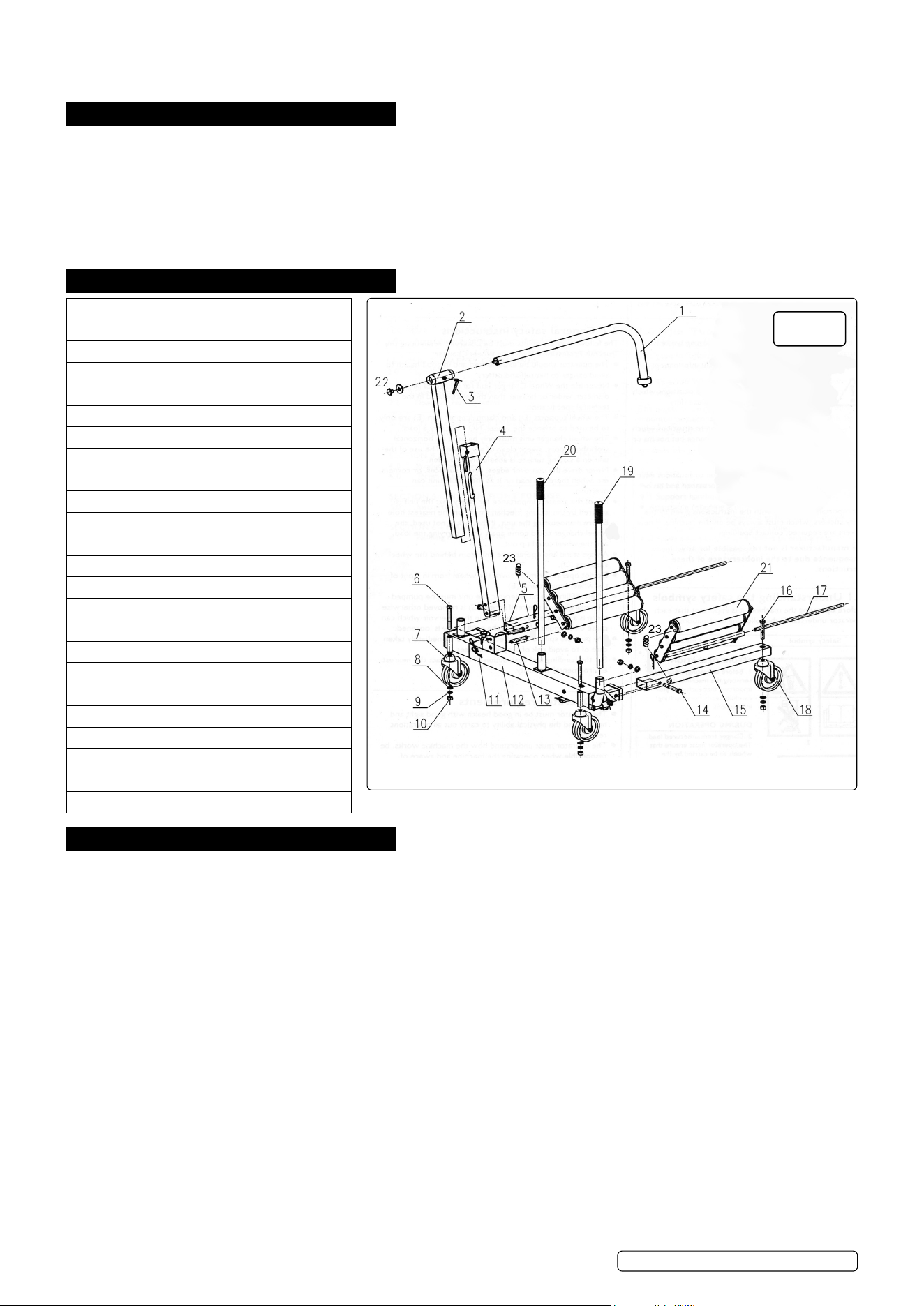
4. ASSEMBLY LIST
5. ASSEMBLY
5.1. Refer to g.1.
5.2. Ensure that at least two people assemble the trolley.
5.3. Fit support frame (left) (5) to frame (12). Use bolt M16 x 110mm (14), at washer 16mm (8), spring washer 16mm (9) and nut M16
(10).
5.4. Fit support tube (right) (15) to frame (12). Use bolt M16 x 110mm (14), at washer 16mm (8), spring washer 16mm (9) and nut M16
(10).
Note: Support frames are not handed. Ensure warning symbols are upwards and visible on trolley.
5.5. Fit braked castors (7) to frame (12). Use bolt M16 x 130mm (6), at washer 16mm (8), spring washer 16mm (9) and nut M16 (10).
5.6. Fit unbraked castors (18) to end of support frame (left) (5) and support frame (right) (15). Use bolt M16 x 100mm (16), at washer
16mm (8), spring washer 16mm (9) and nut M16 (10).
5.7. Fit roller tables (21). Get one person to hold table whilst other inserts mounting bar (17) with R clip hole end going in rst. Secure
with R clips (11).
5.8. Fit roller table tension springs (23). Insert top end of spring into hole on end of roller tables (21) and the other end of the spring into
nut welded onto the inner edges of support frame (right) (15) and support frame (left) (5).
5.9. Fit wheel support (4) to frame (12) with handle to rear. Use pin (13) and R clip (11). Ensure R clips are on outside of frame as
shown in g.1.
5.10. Insert clamp support arm (1) into sliding tube (2), (remove hand wheel and washer (22) rst), tighten clamp (3). Insert into wheel
support (4), tighten clamp on wheel support (4).
5.11. Insert handles (19 and 20) into sockets shown in g.1.
5.12. PURGE HYDRAULIC SYSTEM
5.12.1. Open the release valve by pressing down the lowering pedal (Fig.2 ).
5.12.2. Pump the handle a minimum of twenty full strokes.
5.12.3. Close the release valve by lifting the pedal back to its highest position.
Part Description Quantity
1 Clamp support arm 1
2 Sliding tube 1
3 Adjustment clamp 2
4 Wheel support 1
5 Support frame (left) 1
6 Bolt M16x130mm 2
7 Braked castor 2
8 Flat washer 16mm 6
9 Spring washer 16mm 6
10 Nut M16 6
11 R clip 4
12 Frame 1
13 Pin 2
14 Bolt M16x110mm 2
15 Support frame (right) 1
16 Bolt M16x100mm 2
17 Mounting bar 2
18 Castor 2
19 Handle 1
20 Handle 1
21 Roller table 2
22 Handwheel + washer 1
23 Spring 2
Fig.1
Original Language Version
© Jack Sealey Limited
W1200T.V3 Issue 2 (H,5,F) 16/08/23
6. OPERATION
6.1. USING THE WHEEL CHANGER TO REMOVE A WHEEL Refer to g.2
6.1.1. Position the vehicle on a suitable horizontal oor and apply the brake.
6.1.2. Jack up the axle of the wheel to be changed with a suitable jack, so that it is clear of the oor. Secure with axle stands.
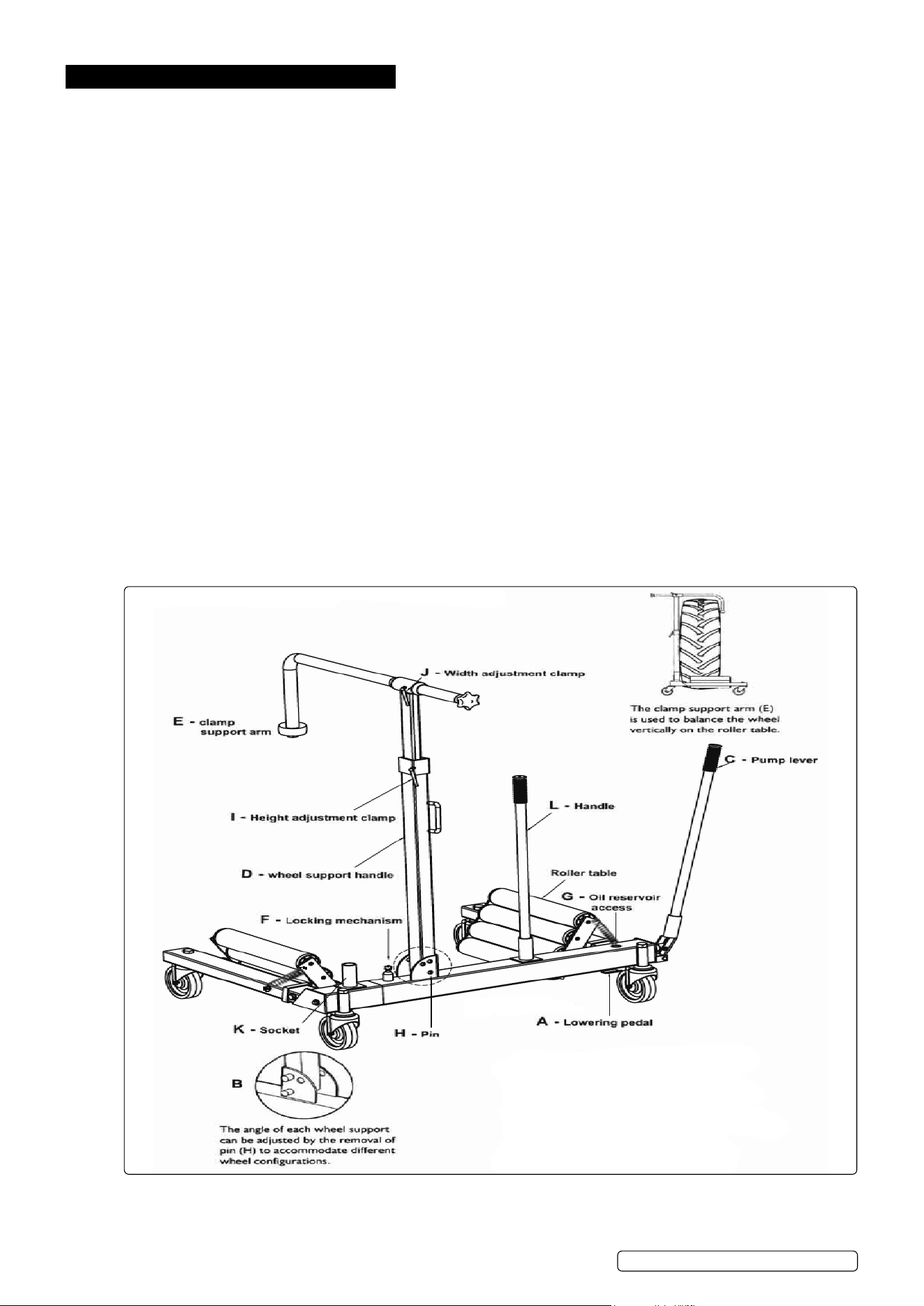
6.1.3. Press down the lowering pedal (A).
6.1.4. Pump the wheel changer apart with the pump lever (C).
6.1.5. Adjust the wheel support (D) so that the clamp support arm (E) is positioned over the wheel to be handled.
6.1.6. Push the wheel changer unit under the wheel so that the roller tables are positioned either side of the wheel and that the wheel sits
up against wheel support (D).
6.1.7. Check that the lowering pedal (A) is in its uppermost position. Pump the unit together until the wheel and the unit cannot glide apart.
6.1.8. Lower the clamp support arm (E) behind the wheel and adjust until the wheel is vertical and can be moved approximately 5cm
sideways. This will allow the wheel to be rotated in the wheel changer when relocating wheel studs. Lock the clamp support arm in
position by tightening adjustment clamps (I and J).
Note: the angle of the wheel supports can be adjusted by the removal of pin (H) to accommodate different wheel congurations,
see g.2.B.
WARNING! Wheel support (D) and clamp support arm (E) are only used to balance the wheel NOT to carry a load!
6.1.9. Lift the wheel by pumping the lever (C). When the wheel is positioned on the unit the wheel changer must be secured in the lifting
position with the locking mechanism (F).
▲ IMPORTANT: Ensure that the locking mechanism (F) is secured through the nearest location hole on the inner member. This
prevents unintentional lowering of the wheel while it is being handled.
6.1.10. With the wheel nuts removed the wheel can now be safely carried away on the wheel changer.
6.1.11. Put pump lever (C) into socket (K). Use with handle (L) to push the wheel changer.
6.2. UNLOADING THE WHEEL CHANGER Refer to g.2.
6.2.1. When the wheel is located on the wheel studs and secured with the wheel nuts or the wheel has been moved to a place for storage,
the wheel can be released.
6.2.2. Loosen clamp support (E) by releasing adjustment clamps (I and J).
6.2.3. Lift and release locking mechanism (F).
6.2.4. Press down the lowering pedal (A). Pump apart the wheel changer with the pump lever (C).
6.2.5. Adjust the wheel support arm (E) so that it does not catch on the top of the wheel before manoeuvring the wheel changer clear of
the wheel.
6.2.6.
Original Language Version
© Jack Sealey Limited
W1200T.V3 Issue 2 (H,5,F) 16/08/23

7. MAINTENANCE
7.1. Daily: Check for damage and uid leaks.
7.2. Every 8 working hours: Check hydraulic oil level. Remove the oil reservoir ller plug, g.2.G, and check the oil level. Top up as
necessary using approved hydraulic oil only. Correct oil level should be at the bottom of the threads of the oil reservoir ller plug
aperture. (Sealey part no.HJO500MLS/HJO5LS).
7.3. Monthly: Lubricate moving parts and check for abnormal wear and tear.
▲ IMPORTANT: NO RESPONSIBILITY IS ACCEPTED FOR INCORRECT USE OF THIS PRODUCT.
Hydraulic products are only repaired by local service agents. We have service/repair agents in all parts of the UK.
DO NOT return the trolley to us. Please telephone us on 01284 757500 to obtain the address and phone number of your local
agent. If the trolley is under guarantee contact your local Sealey dealer.
8. TROUBLESHOOTING
8.1. Roller tables will not extend to their full width - low hydraulic level. Check and ll see section 7.1.
8.2. Pump lever ineffective - hydraulic oil level too high. Check and drain see section 7.1.
Original Language Version
© Jack Sealey Limited
W1200T.V3 Issue 2 (H,5,F) 16/08/23
Sealey Group, Kempson Way, Suffolk Business Park, Bury St Edmunds, Suffolk. IP32 7AR
01284 757500 sales@sealey.co.uk www.sealey.co.uk
ENVIRONMENT PROTECTION
Recycle unwanted materials instead of disposing of them as waste. All tools, accessories and packaging should be sorted,
taken to a recycling centre and disposed of in a manner which is compatible with the environment. When the product
becomes completely unserviceable and requires disposal, drain any fluids (if applicable) into approved containers and
dispose of the product and fluids according to local regulations.
Note: It is our policy to continually improve products and as such we reserve the right to alter data, specifications and component parts without prior notice.
Important: No Liability is accepted for incorrect use of this product.
Warranty: Guarantee is 12 months from purchase date, proof of which is required for any claim.
REGISTER YOUR
PURCHASE HERE