
Intraoral Digital Impression Instrument
Instruction for Use
MODEL:PANDA P4


1. General Information
2. Product Information
3. Product Composition
4. Main Dimension
5. Intended Use and Contraindication
5.1 Intended Use
5.2 Users
5.3 Contraindication
6. Environmental Requirements
7. Working Power Requirements
8. Safety Information
8.1 Prerequisites
8.2 Mechanical Hazards
8.3 Explosion Hazards
8.4 Electrical Safety
8.5 Eye Safety
8.6 Cautions
1
2
4
5
5
5
6
6
7
8
8
8
11
11
12
14
15
CONTENTS

9. Product Hardware Installation Instructions
10. Product Software Description
10.1 Software Operation Configuration Requirements
10.2 Software Basic Information
10.3 Software Installation Method
10.4 Main Software Interface
11. Application Method
11.1 Operating Steps
11.2 Scan Technique
11.3 Calibration
12. Care and Maintenance Methods
13. Service Life
14. Parts List
15. Revision History
16. Legend of Labels and Symbols
17. Other Contents
17.1 Liability of the Manufacturer
17.2 Warranty Description
18. About EMC Descriptions and Risk Warning
19. Customer Support
16
19
19
20
21
21
22
22
22
24
25
28
28
29
29
32
32
32
34
44
1. General Information
The symbols used in this document imply the following:
1
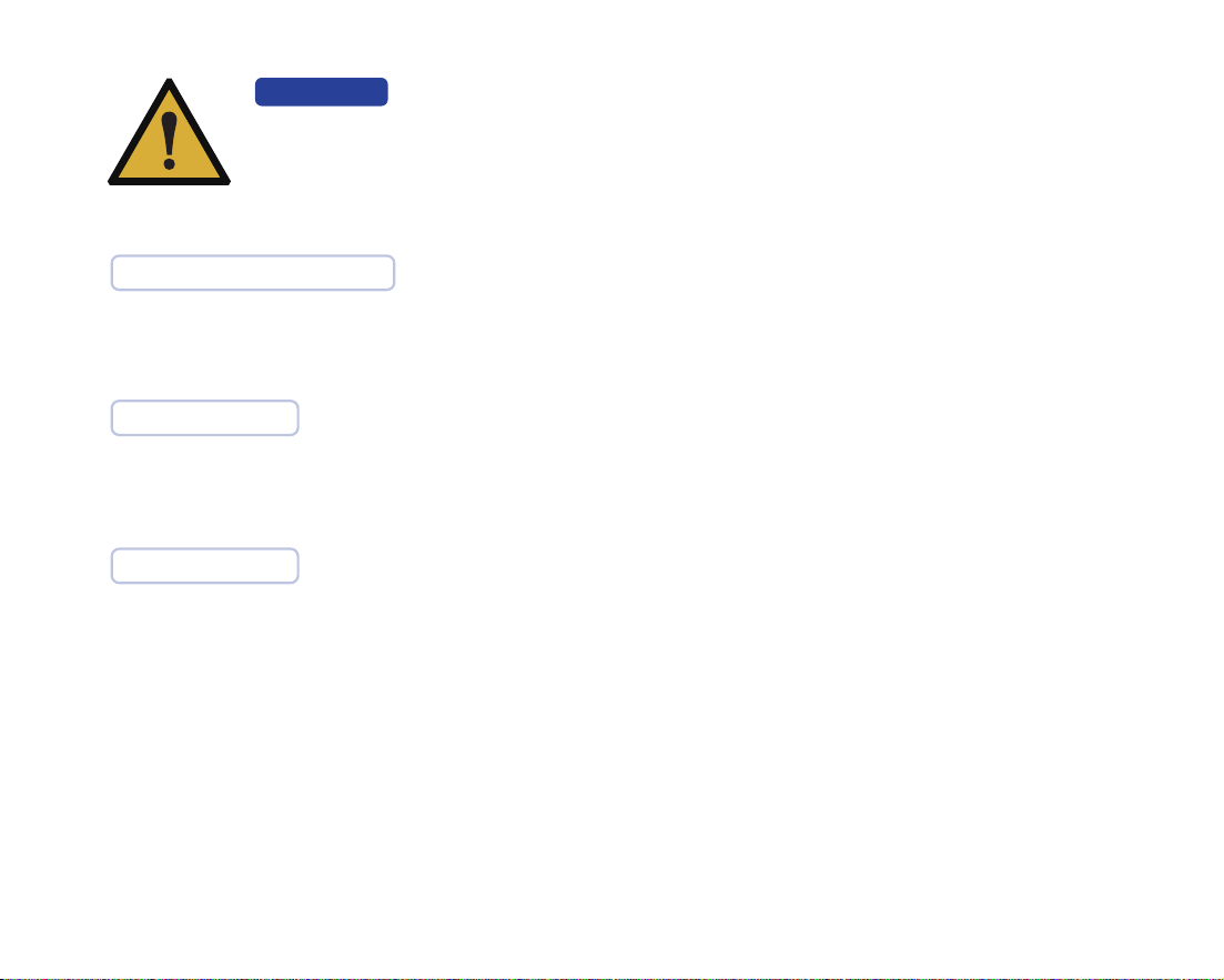
Be sure to observe all warnings!
Please observe all safety information and warnings to prevent personal
injury material damage or damage to your instrument.Safety informa-
tion and warnings are highlighted in this IFU using the words WRNING,
CAUTION.
CAUTION
WARNING
CAUTION
Safety information where hazards such as:loss of data, invalidation of
warranty or service contract, risk of property damage, damage to the
instrument exist if the information is not observed.
Warnings regarding situations where a risk of injury to person exists if
the information is not observed.

2. Product Information
2
Product Name
Model
Manufacturer
Address
Manufacturer
Name
Manufacturer
Contact
Protection against
electric shock
Intraoral Digital Impression Instrument
PANDA P4
Ziyang Freqty Medical Equipment Co.,Ltd.
Floor 2-3, unit 7, building 3, No. 222, West Section 3, outer ring road,
Yanjiang District, Ziyang City, 641300,Sichuan Province,P.R. China
Class II, internal power supply; The calibrator is connected to an independent
power supply (computer) for power supply
Tel: +86-028-26577388 | E-mail : sales@freqty.com , support@freqty.com
Product consultation: sales@freqty.com. After-sales service: support@freqty.com
1
1

3
Applied part
Defibrillation-proof
applied part
Method of sterilization
Suitability for use in an
ox rich environment
Mode of operation
Protection against
harmful ingress of
water or particulate
matter
Type B
No
IPX0
By moist heat such as by autoclave (scanner head)
No
Continuous operation
4
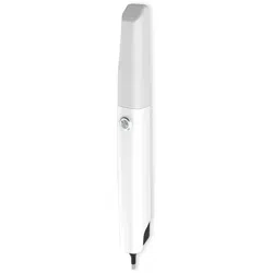
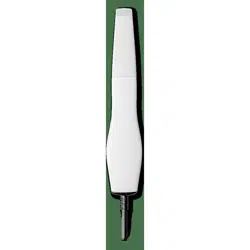
3. Product Composition
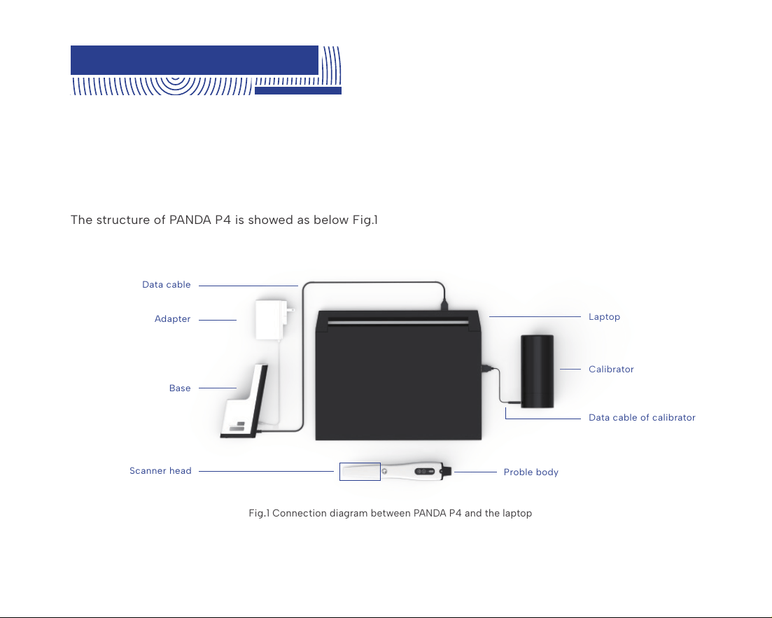
The product is composed of the probe,the adapter, the calibrator, the base and the supporting
software (release version: P4V1) . The probe includes the probe body and scanner head (include
normal scanner head, D scanner head and M scanner head).
The scanner head is applied part.
The structure of PANDA P4 is showed as below Fig.1
Fig
.
1 Connection diagram between PANDA P4 and the laptop
Laptop
Calibrator
Data cable of calibrator
Proble body
Adapter
Data cable
Base
Scanner head
2
The product do not include the laptop.
2

5
Size of scanner head
(length, width and height)
Total size
Normal scanner head: 83*19*14mm,window:18*16mm
D scanner head: 82*20*16mm,window:18*20mm
M scanner head: 88*20*16mm,window:18*18mm
238mm (L) *42mm (W) * 35mm (H)
4. Main Dimension
5. Intended Use and
Contraindication
This product uses the optical scanning method to obtain the three-dimensional shape feature
data of the surfaces of teeth, gums and other tissue. It outputs the three-dimensional digital
impression data which can be used in the CAD / CAM denture design and processing.
5.1 Intended Use

6
WARNING
Unintended use of instrument can results in physical injury to patients,
operators and damage to the product.
The product may be operated only by trained dental professionals and qualified personnel.
5.2 Users
Patients with the following contraindications are not suitable for intraoral digital impressions.
These contraindications include but are not limited to:
1. Patients have oral mucosal disease; patients have mental illness; patients have Parkin-
son's disease; patients have ADHD (Attention Deficit and Hyperactivity Disorder); patients
have epilepsy.
2. If the patient's teeth have very severe black smoke stains that interfere with optical
scanning, the smoke stain area can be sprayed with powder for optical enhancement..When
optically enhanced powder spraying is required, patients suffering from diseases that
cannot accept powder spraying are contraindications, mainly including but not limited to:
allergy or multiple drug allergies, severe respiratory diseases and asthma patients, etc.
3. It should not be used on patients who have or have had photobiological reactions
(including those with excessive sun exposure or porphyria) or who have been treated with
photosensitive drugs (including methoxsalen or chlortetracycline).
5.3 Contraindication

7
6. Environmental Requirements
Temperature
Operating conditions
Operating
Environment
Relative
Humidity
5℃ ~ 30℃
Home healthcare environment and professional healthcare facility environment.
Indoor operation, prevent direct sunlight and strong lights, and keep away from
electromagnetic sources, cold and heat sources, and vibration sources
≤80%
Atmospheric
Pressure
700hPa ~ 1060hPa
Temperature
Transport conditions
Relative
Humidity
-10℃~55℃ ≤93%
Atmospheric
Pressure
700hPa ~ 1060hPa
Temperature
Storage conditions
Atmospheric
Pressure
Storage
Environment
Relative
Humidity
-10℃~55℃
700hPa ~ 1060hPa
Well-ventilated, non-corrosive gas chamber. Prevent moisture, corrosion, avoid
direct sunlight.
≤93%

8. Safety Information
8.1 Prerequisites
Read all instructions carefully including all warnings and cautions. You must comply
with the warnings in the IFU to prevent injury to persons and damage to Intraoral
Digital Impression Instrument(hereinafter referred to as instrument). Proper
functionality and safety can only be guaranteed if the safety precautions in this IFU
and on the instrument are observed.
CAUTION
8
7. Working Power Requirements
The base is powered by a power adapter.
Certified by IEC60601-1:2005+ A1:2012
Model: UES36LCP2-120300SPA
Input: 100-240V~ 50/60Hz, 1.0-0.5A
Output: 12V⎓3A, 36W
The handheld part is powered by an internal lithium battery, which is charged in the base.
Operating voltage: 3.6V
Battery capacity: 3200mAh, continuous operation: 2.5 hours

9
WARNING
No modification of this instrument is allowed.
Modification of the instrument
Approved software only
Install only approved software to prevent interference with the runtime reliability of
the instrument and programs within it.
CAUTION
CAUTION
Please examine the instrument for any mechanical damage on:
All enclosures
All cables
Safety can only be guaranteed if NO DAMAGE on the instrument is observed.
Preventive inspection before use of the instrument
10
In case of instrument failure
WARNING
If at any time the instrument malfunctions, or if you suspect in any way that the
instrument is not working correctly:
Remove the instrument from contact with the patient.
Unplug the probe and make sure it cannot be used before it is checked.
Contact your reseller.
DO NOT attempt to open any covers on the instrument.
Proper training
Before you attempt to use the device with patients.
You should be trained to use the device or have read and understood all sections of
this specification describing correct operation.
CAUTION
You should also be thoroughly familiar with the safe operation of the device as
described in this documentation.

11
8.2 Mechanical Hazards
Dropped or damaged instrument
If the probe body is dropped or bumped it should immediately be calibrated before
further use. If calibration fails, please contact your technical service provider. See
instructions on Calibrating the instrument.
CAUTION
WARNING
If you drop a scanner head on the floor, you MUST dispose of it immediately and
NOT use the same scanner head again for scanning.
There is high risk that the mirror in the scanner head has become dislodged and
can fall out.
8.3 Explosion Hazards
Environment
WARNING
The product is not designed to be used in environments that are potentially
explosive such as in close proximity to flammable liquids or gases or in
oxygen-enriched atmospheres.

12
8.4 Electrical Safety
The power interface
Only be connected to the USB interface of UL/CSA 60950-1 certified computer
equipment.
Please contact the manufacturer when the data cable used for power supply
needs to be replaced. Do not replace it by yourself.
CAUTION
Stress on cables
All externally connected cables must never be subjected to pulling stress.
CAUTION
Electrical shock
WARNING
There is a risk of electrical if you attempt to access the inside of any part of the
instrument. Only authorized and qualified service personnel may access the
inside of any part of the instrument.

13
Do not remove the battery, otherwise the device cannot be used.
CAUTION
Disconnected from mains
WARNING
There is no power ON/OFF switch on the instrument therefore the only reliable
means to disconnect the device from mains is unplug the data cable used for
power supply. Do not position the instrument so that it is difficult to unplug the
data cable.
Internal batter
WARNING
Personnel not authorized by the manufacturer are not allowed to replace the
internal battery. Incorrect replacement could result in HAZARDS (such as device
damage, excessive temperatures, fire, or explosion).
Spilled Liquids
WARNING
Do not bring liquids such as beverages near the instrument.
Do not spill liquids on the instrument.
14
8.5 Eye Safety
Visible laser.
WARNING
Do not look into the visible laser beam in the process of use, and prohibit the
beam of the scan window (laser window) from directly hitting the operator and the
patient's eyes.
The laser wavelengths used by the product are 450nm and 520nm.Both beam divergence angles(Par-
allel) are 9°,beam divergence angle(Perpendicular) are 44° and 49°. The pulse width is 60μs. The
repetition frequency is 15Hz, and the maximum power is less than 0.5mW. The warning label related
laser product has been affixed to the external surface of the product which can be clearly seen. After
use, please place the probe on the probe bracket with the scanning window facing down.
WARNING
The patient should wear goggles before starting scanning.
The requirements for goggles are as follows: protection wavelength 200-540nm, OD4+ (transmit-
tance of 0.01%), visible light transmittance of 60%. Goggles should be kept properly after use, for
example, put them in a glasses case.

15
8.6 Cautions
WARNING
The instrument emits white light from the scanner head during operation. The
instrument complies with EN(IEC)62471(Photobiological safety of lamp and lamp
systems). However, we recommend caution when handling the instrument.
A brief glimpse of the light into eye is not dangerous, but do not gaze at the beam
or view directly at it with optical instruments, and do not aim the beam towards
other people’s eyes.
This product is an optical scanning instrument, during the use of the product must not be vigorously
collision.
Please take good care of the calibrator in the product. Once the calibrator is stained, the performance of
the product will be degraded
This product meets the requirements for electromagnetic compatibility of medical devices in use, but it
is not recommended to use it in environments with strong magnetic fields, strong switches and strong
light sources, otherwise it may affect the performance of the product.
After the product is used at the end of its life, the product should be disposed of in accordance with the
requirements of local laws and regulations, or contacted by the manufacturer for recycling and central-
ized disposal in accordance with local laws and regulations.
9. Product Hardware Installation Instructions
16
This product is a precision optical instrument. Manufacturers and distributors shall not be liable for the
loss of product safety and reliability and performance if the operator do not operate in accordance with
the instructions, or if they do not use the product in a collision and fall due to improper use. After falling,
please check the product function and calibrate the product with a calibrator. If the calibration fails,
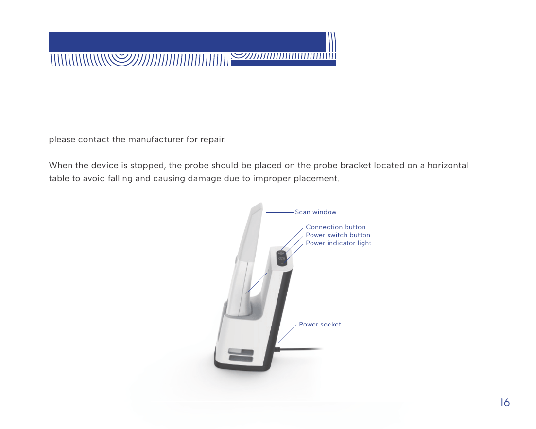
please contact the manufacturer for repair.
When the device is stopped, the probe should be placed on the probe bracket located on a horizontal
table to avoid falling and causing damage due to improper placement.
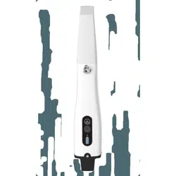
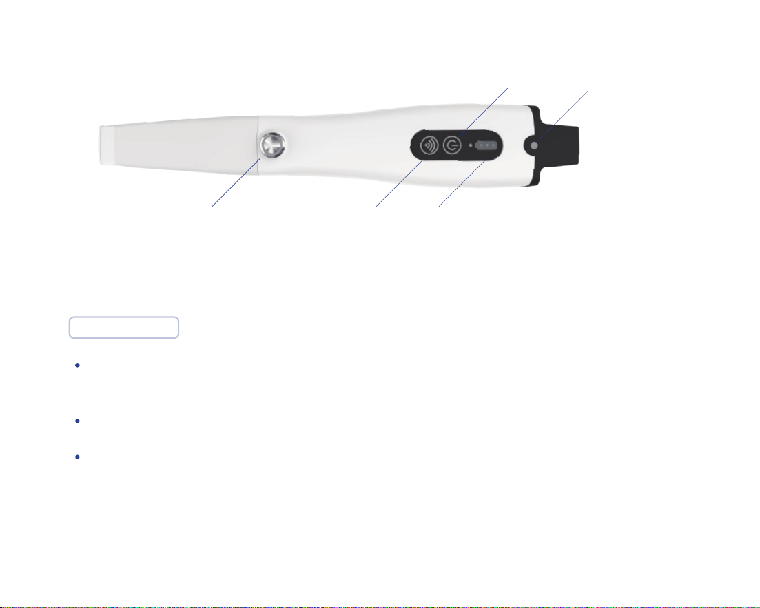
Connection button
Scan window
Power switch button
Power indicator light
Power socket
Connection indicator light
Fig
.
2 Probe in base

17
Plug a power adapter into the base's power jack.
The base connects to the USB3.0 port of the user's computer via USB3.0 of the data cable.
Press the power button on the base to turn on the power, and a green indicator lights up. Long press
will turn off the power, the indicator light off.
Press and hold the power button on the body of the probe, and the white indicator light of the
function button lights up. Long press the power button again to turn off the power. The white
indicator light of the function button will turn off, and the power indicator light will turn off after a
period of delay.
Connection indicators on the probe and base are not on for not connected, blue for being connect-
ed, and green for successful connection. In general, the probe and base of a device have been
pre-connected and paired, and no further connection is required.
Run the scanning software and scan according to the requirements of the scanning operation.
During normal scanning, light is projected from the scanning window.
After scanning, place the probe on the base to prevent accidental fall damage. After the probe is
placed on the base, it will charge the probe, and the probe will automatically turn off the power after
a period of time.
Installation step:
18
Please note:
Function button Connection button Battery indicator light
Power switch button Connection indicator light
Keep the probe and the base within the range of 2m, and there is no obvious hindering object
between the probe and the base, ensuring wireless stable connection and stable transmission.
When the power indicator light on the probe is only one light, please charge in time.
When the instrument is working, the power of the heating element on the scanning head is 0.35w.
Fig
.
3 Plan view of probe

19
10. Product Software Description
10.1 Software Operation Configuration Requirements
This product can only be used by installing software on the computer. The requirement for the recom-
mended configuration of computer hardware is no less than the following configuration:
CPU
GPU
Memory
Hard disk
Display
Intel i7-8700(3.2GHz)and above
NVIDIA GTX1060 (6G) and above
DDR2400 16G and above
Solid state drive SSD 120G and above
Resolution 1920×1080 and above

20
10.2 Software Basic Information
Software Name
Release Version
Software
Security Level
Network security
Data saving
format
Intraoral Digital Impression Instrument Scan Software(PANDA SCANNER)
User access control can choose to use user name and password for identity
authentication. The user type is ordinary user. Ordinary users can use the
instrument normally and view data results. The login interface is shown in the
figure below。
standard STL, PLY format and PTY format defined by our company
P4V1
A
Fig.4 Login interface
Account:
Password:
Login Logout
21
10.3 Software Installation Method
The File name format of installation file in the USB Flash Drive Accompanying is PANDAP4V1 X.X.X
XXX. Full. exe format. The installation steps are as follows:
The installation steps can be found in the Instrument Software Operation Manual.
1. Double-click to open the installation file;
2. Carefully read the license agreement and choose to agree;
3. Click next according to the prompts;
4. The uninstallation is completed, select "Yes" to continue the installation[ If the user has not
installed the company's software, this interface will not appear.] ;
5. Finished.
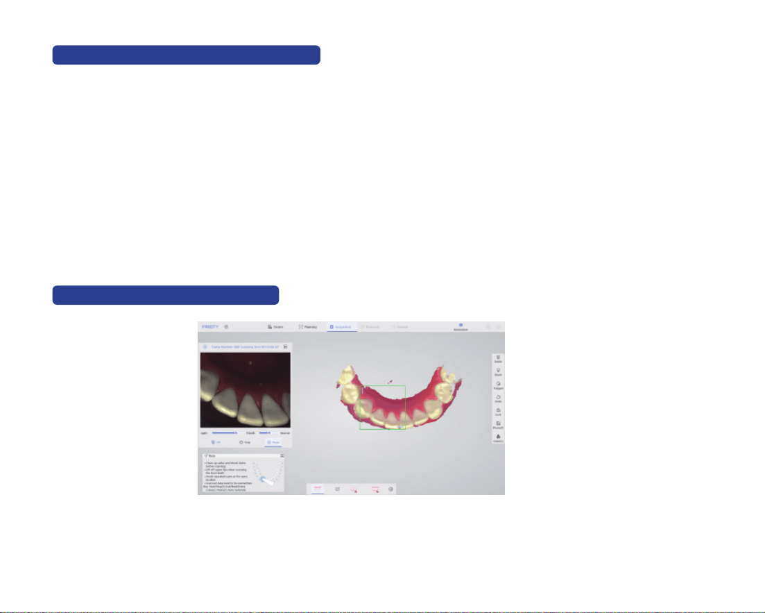
10.4 Main Software Interface
The specific method of use of the software is provided by the company with training materials
and operation manuals.
Fig.5 Main interface

22
11. Application Method
11.1 Operating Steps
Follow the instructions for Product Hardware Installation in Chapter 9.
Open the software and scan after the startup is complete. During the scanning process, the function
button can be used to control the start, pause and end of the scan.
11.2 Scan Technique
Hold the probe body in the same way as a pen while scanning, Due to the limitation of the actual space
in the mouth, it is necessary to ensure that the head window of the probe is as close to the tooth
surface as possible (it is recommended to keep it within 2mm) for scanning, and the operation mode of
suddenly far and suddenly near should be avoided.
In general, a normal probe is used for scanning, which can be used for partial or full scanning opera-
tions. For some special cases (such as insufficient mouth opening, or severe occlusion between teeth),
D probe can be used to supplement the missing area of the distal surface, or the M probe can be used
to supplement the missing area of the mesial surface. Please refer to the following figure to select the
probe.

23
Fig.6 mesial surfac and distal surface schematic diagram
Axial drag of the probe was the main scanning method, and radial drag of the probe was used in the
scanning of the front teeth and occlusion points. Start scanning from the end teeth, first scan the
oeclusal data, then scan part of the buccal and lingual data, and drag from oeclusal to mesial to scan
the next tooth, and follow the same operation to complete the frame scan of the posterior tooth area.
When entering the lingual surface of the anterior tooth area, drag the probe radial direction left and
right to scan the lingual surface and incisal data, and then scan part of the labial surface data after the
lingual surface is completed.

24
11.3 Calibration
According to the usage, it is recommended to use the calibrator to calibrate the product
once a week. The product has not been used for three months, it is recommended to
calibrate before use. When the device is impacted, or the product is moved or vibrated
greatly, or in order to maintain the accuracy of the scanning accuracy, the scanner needs to
be calibrated. Refer to "Operation Manual" for the calibration method.
The calibrator of the product should be properly kept. Once the calibrator is
defaced, the performance of the product will be degraded.
CAUTION

25
12. Care and
Maintenance Methods
Recommended sterilization method:
The product is not expected to have long and frequent oral contact with patients. The scanner
head must be cleaned and sterilized between patients to avoid cross contamination. It is recom-
mended to sterilize the scanner head by means of moist heat steam sterilization (121 °C, 15 min or
134 °C, 6 min).
The scanner head should be replaced when the appearance is damaged or the times of sterilizations is
20. The scanner head can be purchased separately from the seller or manufacturer.
Clean the scanner head with soapy water and a soft brush, then place it under running water
for rinsing.
Wipe the water stain on the surface of the scanner head with medical gauze and wipe it
thoroughly with absolute alcohol. Pay special attention to whether there are stains or water
stains on the head mirror. If there is, use another medical gauze to draw the absolute alcohol
and carefully wipe the head mirror. The sample was allowed to stand for two minutes after
wiping.
WARNING
In order to ensure the normal performance of the product, it is recommended
that the times of repeated sterilization of the scanner head shall not more than
20.

26
Keep the outside of the product clean.
If the reflector of the scanner head is stained, users can dip the degreasing cotton into a small amount
of anhydrous alcohol (99.9%), and then gently wipe the reflective surface, rotating from the center to
the periphery. If the reflector is scratched, it needs to be replaced.
In the course of instrument, software errors and warnings can be self-healed by the software. Serious
problems may require shutting down the software and restarting. General hardware errors can be
restored by turning off the power and then turning the power back on. If something cannot be
recovered, contact the manufacturer or the seller.
Place the scanner head which had been cleaned into 90* 260mm Self-sealing sterilization pouch
(materials: Medical high-temperature dialysis paper and medical CPP/PET complex film) and
seal the sterilization pouch. Then place the packaged scanner head into sterilizing instrument
tray.
Place the sterilizing instrument tray into a small pressure steam sterilizer and set the sterilization
parameters according to the instructions of the small steam sterilizer: temperature 121 ° C, 15
min, or temperature 134 ° C, 6 min.

27
Replacement instrument parts must be obtained from the manufacturer or manufacturer
approved dealer.
The maintenance personnel must take laser protective measures during the inspection process,
such as wearing goggles.
The parts that not supplied by the manufacturer may reduce the accuracy and
safety of the instrument.
CAUTION
WARNING
During the inspection, ensure that there is no person in the direction of laser
irradiation.
Disclaimer: We can provide the necessary information for maintenance instrument to the
users with corresponding maintenance qualifications.
The instrument shall not to be services or maintained in use with a patient.
CAUTION

28
Expected service life: 5 years.
Over period of use, the degradation of the product's main electronic and optical
components may reduce product performance.
CAUTION
Parts Name Quantity
Probe body
Base
Calibrator
Adapter
Protective Casing
Calibrator cable
scanner head
IFU
Qualified label
Warranty card
USB Flash Disk
1
1
1
1
1
1
5
1
1
1
1
13. Service Life
14. Parts List
29
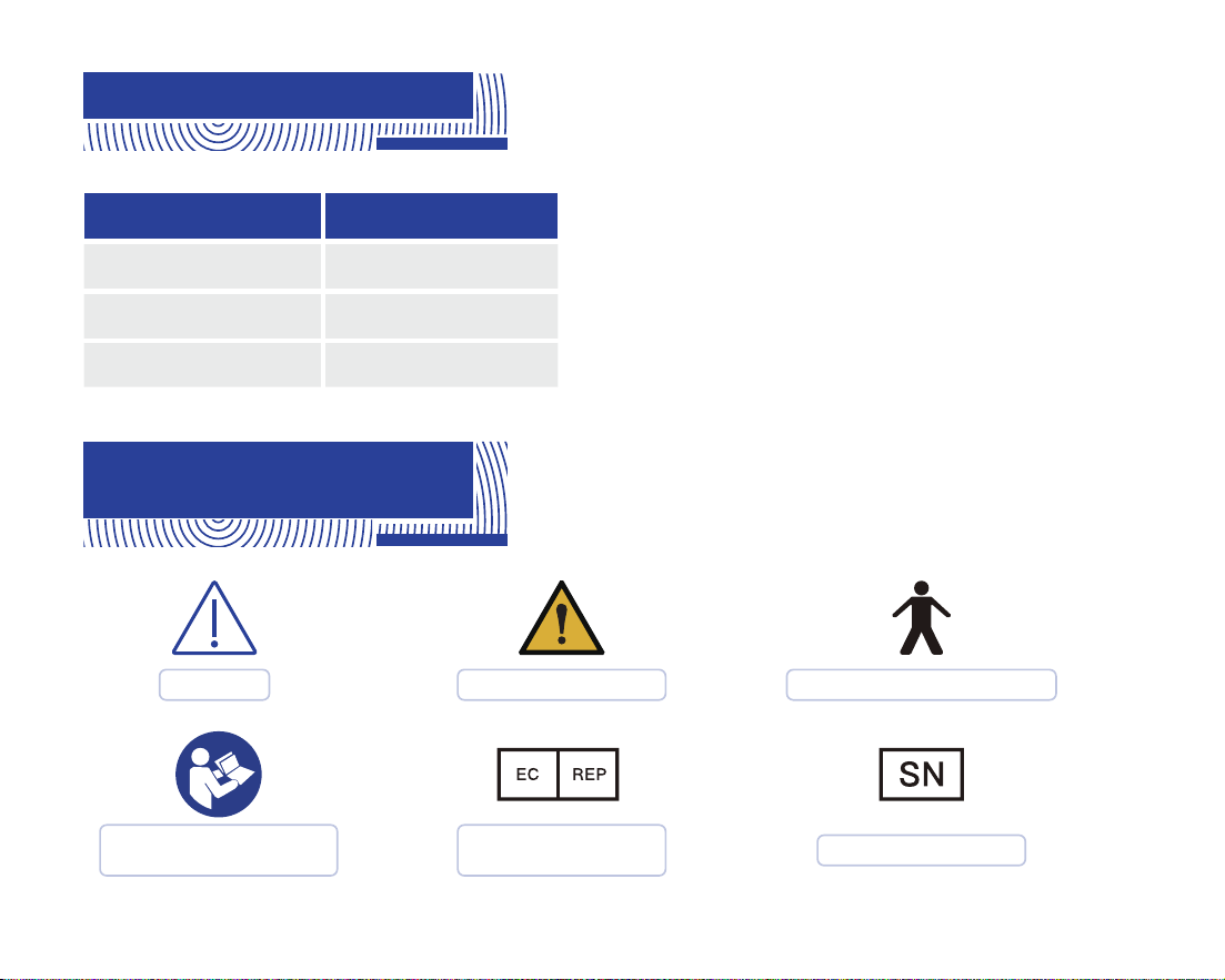
15. Revision History
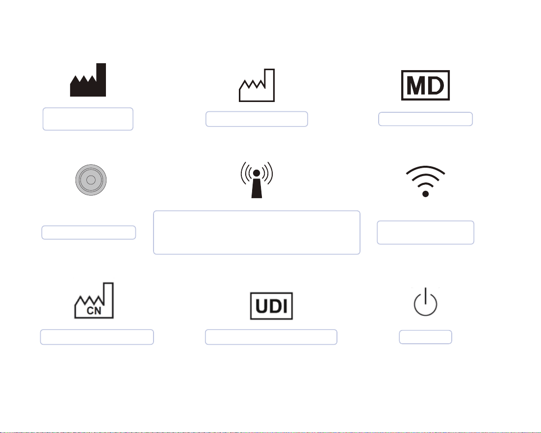
16. Legend of Labels
and Symbols
Edition Date
A.00
A.01
A.02
2023.03.01
2023.12.06
2024.03.07
Caution
EU Authorized
Representative
General Warning Type B Application Part
Refer to instruction
manual/ booklet
Serial Number
30
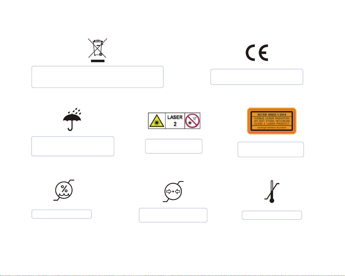
The device should be sent to the special
agencies according to local regulations for
separate collection after its useful life.
CE marking in conformity with
Regulation (EU) 2017/745
Indicates a medical device
that needs to be protected
from moisture.
Laser Categories
and Warnings.
Laser parameters and
standards.
Atmospheric Pressure
Limitation
Temperature Limit
Humidity limitation
31
External markings for devices or components
of devices that contain radiofrequency
transmitters or use radiofrequency electro-
magnetic energy for diagnosis or therapy.
Medical Device
Manufacturer
Information
Date of Manufacture
Country of manufacture Unique device identification
Function button
Stand by
Wireless connection
button

32
17. Other Contents
17.1Liability of the Manufacturer
17.2 Warranty Description
The installation, adjustment, modification, and repair of this product are performed by persons or
organizations approved by the manufacturer or distributor. And the manufacturer must be able to
ensure the safety of the product in accordance with the electrical, environmental, storage, mainte-
nance, and operation requirements of the manual. Responsibility for reliability and performance.
(1) Non-user subjective destruction within the warranty period, product failure caused only by
product quality;
(2) Product failure caused by force majeure (such as earthquake, flood, typhoon, etc.) during the
warranty period.
The warranty period for this product is one year, calculated from the date of sale (according to
the date of sales invoice).
One of the following cases the company provides free maintenance:

33
(1) Failure of the product due to non-subjective damage by the user during the warranty period;
(2) Failure of the product after the warranty period but within the service period.
(1) The product has been used for more than 8 years;
(2) Product failure caused by subjective destruction of users
One of the following cases the company provides paid maintenance:
We no longer provides maintenance in one of the following situations:

34
18. About EMC Descriptions
and Risk Warning
WARNING
Portable RF communications equipment(including peripherals such as antenna
cables and external antennas) should be used no closer than 30 cm(12inches) to
any part of the product including cables specified by the manufacturer. Otherwise,
degradation of the performance of this equipment could result.
This product has passed the electromagnetic compatibility test and meets the requirements of
EN 60601-1-2 Medical electrical equipment–Part 1-2: General requirements for basic safety
and essential performance–Collateral Standard: Electromagnetic disturbances – Requirements
and tests.
The following application requirements shall be strictly observed during use, otherwise it may
cause electromagnetic interference to other devices or reduce the anti-electromagnetic
interference capability of the therapeutic device, or even lose the basic performance.
This product belongs to the Group 1 Class A equipment specified in IEC/CISPR 11, non-perma-
nent installation equipment, non-living support equipment, and belongs to equipment that is
not expected to be directly connected to the public power grid.

35
No. Name Cable length (m)
Whether the
cable is
shielded
Remarks
1
2
1.5
1
No
Yes
DC power supply line
Data cable of base
\
\
3 0.5 YesData cable of calibrator
\
The cable information of this product is as shown in the following table. If there is a fault in the
connection cable, please contact our company for maintenance or replacement. Other-wise it may
cause excessive electromagnetic interference. If there is something wrong with this product, please
contact our company promptly. Do not repair or replace the components yourself, or it may cause
excessive electromagnetic interference.
WARNING
The use of accessories or cables outside of the regulations together with equip-
ment and systems may result in increased emissions or reduced immunity of the
equipment or system..
WARNING
This product should not be used near or stacked with other devices. If it must be
used close to or stacked, it should be observed and verified to work properly
under its configuration.
36
WARNING
This product is intended for industrial and hospital use (CISPR 11 Class A). If used in
a residential environment (CISPR 11 Class B), RF communications may not be
adequately protected.
Free from distortion in an image or error of a displayed. In the test, the communication was normal during
the continuous scanning process, and the image of the tooth model could be obtained normally.
Pass and Fail Criteria
The device is powered on, connected to the test software, set to continuous scan mode, a dental plaster
model is placed on the front end of the probe for continuous scanning.
Test method
Continuous scan mode. After the device is connected to the power test software, for continuous
scanning.
Work mode

37
Issue Solution
No image display in
2D image area
2D image flicker
- Make sure the device's USB interface is properly connected to
the computer's USB 3.0 interface.
- Restart the software and scanning device to check if the
image can be displayed normally.
- Check if the modulator is connected properly.
- Replace the USB port of the device with the computer.
- Connect your computer to the Internet.
Scans are easily
interrupted and not
smooth
-Inappropriate scan brightness. For plaster model scanning,
choose 1/2, for resin model scanning, choose 3, for the intraoral
scanning, choose 4, 5 is suitable for patients with darker teeth
in the mouth.
-During scanning, confirm that A above the image area is blue.
If it is black, use the keyboard A key to switch.
-Standardize scanning methods. Ensure coverage of scanned
data with existing data.
Trouble Shooting

38
Issue Solution
Out-sync of data
between 2D and 3D
Difficulty for scan
relocation
-Confirm whether the computer configuration meets the
requirements (higher than or equal to our recommended
configuration).
-Delays caused by too many scans (single jaw scans should be
completed within 3 minutes).
-Uninstall antivirus software or add scanning software to the
whitelist of antivirus software.
-Check the status of windows update. If the update is in
progress or has failed, please restart the computer after the
update is completed before using the scanning software.
-Ensure that the scanning direction is consistent with the
previous scanning when repositioning
-Avoid long scans.
-Check the status of windows update. If the update is in
progress or has failed, please restart the computer after the
update is completed before using the scanning software.
-Check whether the remaining storage space of drive C is
sufficient.
-Turn off or uninstall anti-virus software.
No 3D data when
scanning
Abnormal interrupt
during scanning
Recalibration

39
This product declarations to meet
Table 1, Table 2, Table 3 of Contents.
The product intended for use in the electromagnetic environment specified below.
The customers or users should ensure that it is used in such an environment.
RF emission
CISPR 11
Group 1
RF emission
CISPR 11
Class A
Harmonic emission
IEC 61000-3-2
voltage fluctuations / flicker emission
IEC 61000-3-3
Complies
Complies
Manufacturer's Declaration - Electromagnetic Emissions
Emission measurement
Conformity
Table 1

40
electrostatic discharge
IEC 61000-4-2
Contact:± 8 kV.
Air:± 2kV, ±4kV, ±8kV, ± 15 kV
3 V/m
80 MHz – 2,7 GHz
80 % AM at 1 kHz
3 V/m
80 MHz – 2,7 GHz
80 % AM at 1 kHz
Contact:± 8 kV.
Air:± 2kV, ±4kV, ±8kV,
± 15 kV.
Radiated RF EM fields
IEC 61000-4-3
Electrical fast transientburst
IEC 61000-4-4
Surge
IEC 61000-4-5
Conducted RF
IEC 61000-4-6
Power frequency magnetic field
(50Hz and 60Hz)IEC 61000-4-8
Power input line voltage dips,
short interruptions and voltage
variations
IEC 61000-4-11
3 Vrms:
0,15 MHz – 80 MHz
6 Vrms:
in ISM and amateur radio
bands between
0,15 MHz and 80 MHz
80 % AM at 1 kHz
3 Vrms:
0,15 MHz – 80 MHz
6 Vrms:
in ISM and amateur radio
bands between
0,15 MHz and 80 MHz
80 % AM at 1 kHz
0% UT
, 0.5 cycle
At 0°, 45°, 90°, 135°, 180°, 225°, 270°
and 315°
0% U
T
, 1 cycle and 70%UT
,25/30
cycles
Single phase:at 0°
0% U
T
, 250/300 cycles
0% U
T
, 0.5 cycle
At 0°, 45°, 90°, 135°, 180°, 225°, 270°
and 315°
0% U
T
, 1 cycle and 70%UT
,25/30
cycles
Single phase:at 0°
0% U
T
, 250/300 cycles
30A/m. 30A/m.
± 2 kV for power supply lines.
± 1 kV line(s) to line(s).
± 2 kV line(s) to earth.
± 1 kV line(s) to line(s).
± 2 kV line(s) to earth.
± 2 kV for power supply
lines
Manufacturer's Declaration - Electromagnetic Immunity
Immunity Test IEC 60601 Test Level Guidelines Compliance Level
Table 2
The product intended for use in the electromagnetic environment specified below.
The customers or users should ensure that it is used in such an environment.

41
Manufacturer’s declaration-electromagnetic immunity
Test specifications for ENCLOSURE PORT IMMUNITY to RF wireless communications equipment
Test
Frequency
(MHz)
Band
a)
(MHz)
Service
a)
Modulation
b)
Maximum
Power
(W)
Distance
(m)
Immunity Test
Level
(V/m)
Compliance Level
(V/m)
Table 3
The PANDA smart is intended for use in the electromagnetic environment specified below.
The customer or the user of the PANDA smart should assure that it is used in such an environment.
385 380-390 TETRA 400
Pulse
modulation
b)
18 Hz
1,8 0,3 27 27
450 430-470
GMRS 460,
FRS 460
FM c)
±5 kHz
deviation
1 kHz sine
2 0,3 28 28
710
745
780
704-787
LTE
Band 13,
17
Pulse
modulation
b)
217 Hz
0,2 0,3 9 9
810
870
930
800-960
GSM
800/900,
TETRA 800,
iDEN 820,
CDMA 850,
LTE Band 5
Pulse
modulation
b)
18Hz
2 0,3 28 28

42
NOTE: If necessary to achieve the IMMUNITY TEST LEVEL, the distance between the transmitting
antenna and the ME EQUIPMENT or ME SYSTEM may be reduced to 1 m. The 1 m test distance is
permitted by IEC 61000-4-3.
a) For some services, only the uplink frequencies are included.
b) The carrier shall be modulated using a 50 % duty cycle square wave signal.
c) As an alternative to FM modulation, 50 % pulse modulation at 18 Hz may be used because while it does not
represent actual modulation, it would be worst case.
Test
Frequency
(MHz)
Band
a)
(MHz)
Service
a)
Modulation
b)
Maximum
Power
(W)
Distance
(m)
Immunity Test
Level
(V/m)
Compliance Level
(V/m)
(For professional
healthcare)
2450
2400-
2570
Bluetooth,
WLAN,
802.11 b/g/n,
RFID 2450,
LTE Band 7
Pulse
modulation
b)
217 Hz
2 0,3 28 28
5240
5500
5785
5100-
5800
WLAN
802.11
a/n
Pulse
modulation
b)
217 Hz
0,2 0,3 9 9
1720
1845
1970
1700-
1990
GSM 1800;
CDMA 1900;
GSM 1900;
DECT;
LTE Band 1, 3,
4, 25; UMTS
Pulse
modulation
b)
217 Hz
2 0,3 28 28

43
Manufacturer Information
Manufacture: Ziyang Freqty Medical Equipment Co., Ltd.
Address: Floor 2-3, unit 7, building 3, No. 222, West Section 3, outer ring
road,Yanjiang District, Ziyang City, 641300,Sichuan Province,P.R. China
Tel: +86-028-26577388
Email: sales@freqty.com
Website: www.panda-scanner.com / www.freqty.com
European Authorized Representative
Company: SUNGO Europe B.V.
Address: Fascinatio Boulevard 522, Unit 1.7, 2909VA Capelle aan den IJssel, The Netherlands
Contact: Yan Zhang(Ms.)
Tel /Fax: +31(0)10 3034500; +31(0)2021 11106
E-mail: ec.rep@sungogroup.com; [email protected]om
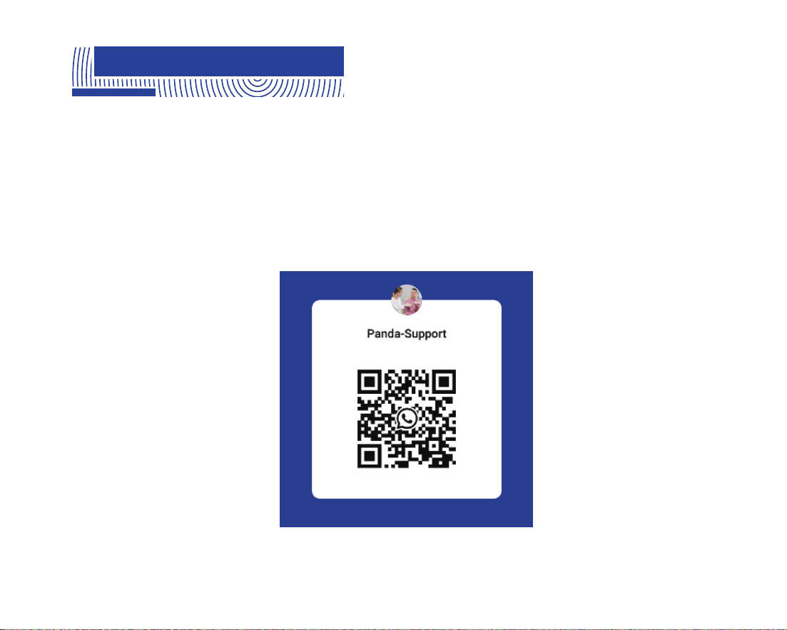
44
Email: support@freqty.com
Toll Free Number (USA): 888-855-2562
WhatsApp (Global): +86 18108286761
19. Customer Support