
PANDA SCANNER
2022 Panda Scanner.All rights reserved.
Room 812,Building 3,Tiandu Tower,No. 211 Changjiang Road,
Suzhou City,Jiangsu Province,China
+86-21-64989018 [email protected]
www.pingtum.com
PRODUCT SPECIFICATION

Create
Maximum Value for
Every User

Caution
Product hardware Installation I nstructions
Product Software Description
Software Operation Configuration Requirements
Software Basic Information
Software Installation Method
Main Software Interface
Care and Maintenance Methods
Transport and Storage Life
Parts List
Graphic Explanation
Other Content
Liability of the Manufacturer
Warranty Description
About EMC Descriptions
& Risk Warning
Product Information
Product Composition
Main Performance
Main Dimension
Specifications
Product Function and lntended Use
Environmental & Working Power
Requirements
01
06
08
10
02
03
12
14
15
16
04
18
Product
Information
Product Name:
Model:
Manufacturer Name:
Manufacturer Address:
Production Address:
Manufacturer contact:
Intraoral Digital lmpression Instrument
PANDA P2
Ziyang Freqty Medical Equipment Co.,Ltd
Zone A, B, C, 4 Floor, Building A, NO.3, Xiandai Road,
Ziyang City, Sichuan Province, China
Zone A, B, C, 4 Floor, Building A, NO.3, Xiandai Road,
Ziyang City, Sichuan Province, China
Tel:+86-21-64989018 E-mail:[email protected]om

Length into the mouth
Depth of field
Total sizet
85mm
15mm
216mm(L)*40mm(W)*36mm(H)
Scanning depth
Scanning accuracy
Repeatability precision
0~15mm
≤15μm
≤10μm
Main Performance
Main Dimension
Specifications
Product
Composition
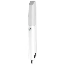
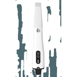
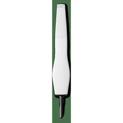
The product is composed of the probe, the power adapter, the calibrator,
the supporting software and the probe bracket. The probe includes the probe body
and P2 probe head assembly.
Scan window
P2 probe head assembly
the probe body
USB data cable

This product uses the optical scanning method
to obtain the three-dimensional shape feature
data of the surfaces of teeth, gums and other
tissue. lt output the three-dimensional digital
impression data which can be used in the
CAD/CAM denture design and processing.
Environmental Requirements
Operating temperature
Storage temperature
Operating humidity
Storage humidity
Atmospheric pressure
Operating Environment
5℃ ~ 40℃
-10℃ ~ 55℃
≤80%
≤93%
760hPa ~ 1060hPa
Indoor operation and avoid
direct to the scanned body
Working Power Requirements
Rate power
Input power
AC 100-240V, 50/60Hz
30VA
Product Function and
Intended Use

This product is a precision optical measur-
ing instrument and must not be impacted
during use. The calibrator in the product
should be properly kept. Once the calibra-
tor is defaced, the performance of the
product will be degraded.
This product meets the requirements for
electromagnetic compatibility of medical
devices in use, but it is not recommended
to use it in environments with strong
magnetic fields, strong switches and strong
light sources, otherwise it may affect the
performance of the product.
This product uses a visible laser light. In the process of
use,please follow “Do not look into the visible laser beam"
requirement, and prohibit the beam of the scan window
(laser window) from directly hitting the operator and the
patient's eyes. The laser wavelength of the product is
450nm and 520nm, the beam divergence angle is 33°, the
pulse width is 25ms, the repetition frequency is 30Hz, and
the maximum power is less than 0.4mW. The related
warning label stickers are delivered to the user along with
the product and are posted by the user on an external
surface of product that can clearly see. After use, please
place the probe on the probe bracket with the scanning
window facing down. The patient should wear goggles
before starting scanning.
The product is not expected to have long and frequent oral contact with patients. lt is recommended to
sterilize the P2 probe head assembly by means of moist heat steam sterilization (121°C, 15min or 134°C,
6min) ; in order to ensure the normal performance of the product, it is recommended that the number of
repeated sterilization of the P2 probe head component is not more than 30 times; the P2 probe head
should be replaced when the appearance of it assembly is damaged or the number of sterilizations is 30
times. The P2 probe head can be purchased by the user by contacting the seller or manufacturer.
Caution
1
Clean the P2 probe head with soapy water and a soft
brush, then place it under running water for rinsing.
2
Wipe the water stain on the surface of the P2 probe
head assembly with medical gauze and wipe it
thoroughly with absolute alcohol. Pay special
attention to whether there are stains or water stains
on the head mirror. lf there is, use another medical
gauze to draw the absolute alcohol and carefully wipe
the head mirror. The sample was allowed to stand for
two minutes after wiping.
3
Place the P2 probe head which had been
cleaned into 90* 260mm Self-sealing steriliza-
tion pouch (materials: Medical high-tempera-
ture dialysis paper and medical CPP/PET
complex film) and seal the sterilization pouch.
Then place the packaged P2 probe head into
sterilizing instrument tray.
4
Place the sterilizing instrument tray into a small
pressure steam sterilizer and set the sterilization
parameters according to the instructions of the
small steam sterilizer: temperature 121°C, 15 min,
or temperature 134 °C, 6 min.
Recommended
sterilization method
This product can only be connected to the USB interface of UL/CSA 60950-1 (or GB4943.1) certified computer equipment.
After the product is used at the end of its life, the product should be disposed of in accordance with the requirements of local laws and regulations,
or contacted by the manufacturer for recycling and centralized disposal in accordance with local laws and regulations.

This product is a precision optical equipment. Manufacturers and distributors shall not be liable for the
loss of product safety and reliability and performance if the operator do not operate in accordance with
the instructions, or if they do not use the product in a collision and fall due to improper use.
When the probe is not scanned, it should be placed on the probe bracket and on the horizontal operat-
ing table as a whole to avoid falling damage caused by improper placement.
The probe is connected to the USB 3.0 port of the user's computer through a cable.
Insert the adapter into the power socket on the product cable, turn on the power switch, and light the
music indicator. Run the scanning software (need to plug the USB Key into the computer) and scan
according to the requirements of the scanning operation. During normal scanning, light is projected
from the scanning window.
After scanning, power should be turned off.
Product hardware
Installation Instructions
Software Basic Information
Software Installation Method
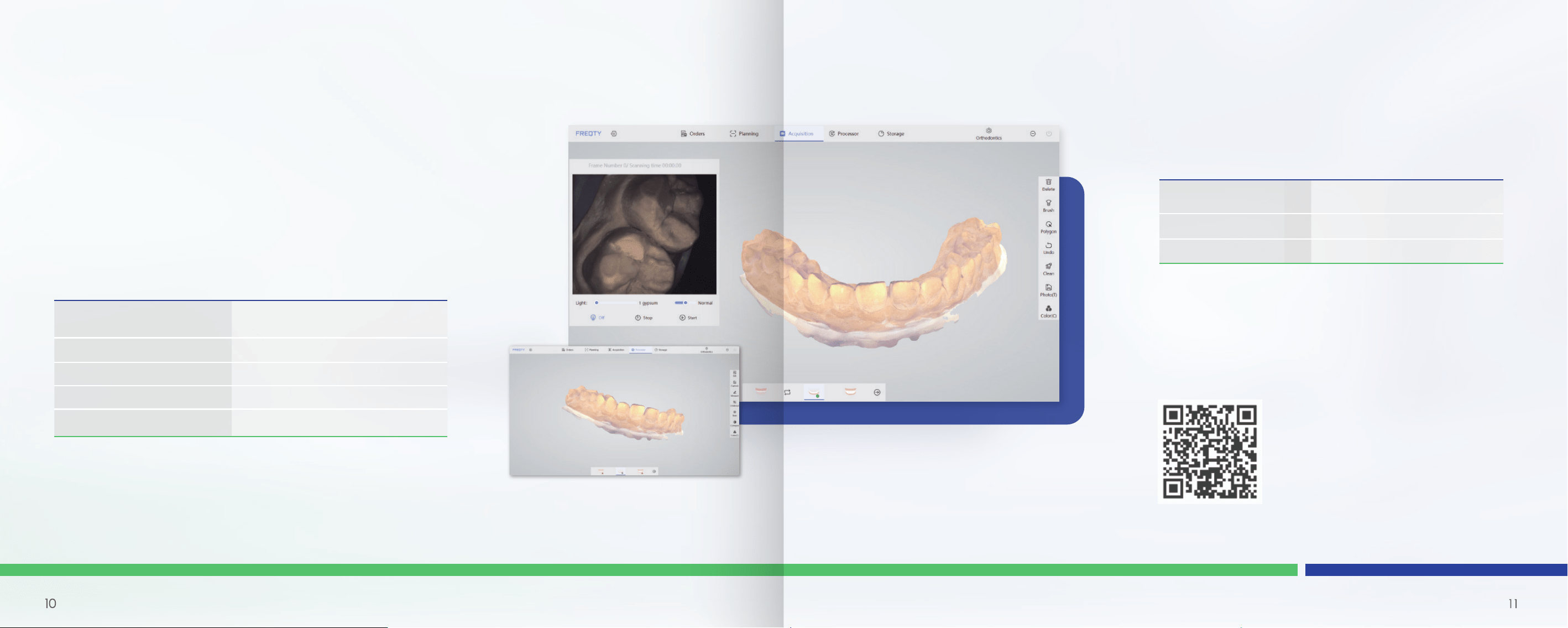
Main Software Interface
Software name
Applicable equipment
Software security level
Intraoral Digital Impression
Instrument Scan Software
PANPA P2
A
Software Operation Configuration
Requirements
CPU
RAM
Hard disk
GPU
Operating system
Intel i7-12700H/
Intel i7-11800H or above
16G/32G
SSD 512G or above
RTX2060/RTX3060 or above
Windows10/11 64bit
The specific method of use of the software is provided by the
company with training materials and operation manuals.
See Intraoral Digital lmpression Instrument (PANDA P2) Software
Operation Manual.
The recommended graphics card is NVIDIA, and the graphics card memory requires more than 6G.
Common unqualified graphics cards are: GTX1650/ GTX1650 Ti/ RTX 3050/ RTX3050Ti
Recommended CPU is Intel, AMD is not supported.
Product Software
Description

When the scan window's reflective glass is soiled, it can be wiped clean with a degreasing cotton with a
small amount of anhydrous alcohol.
ln the course of equipment, software errors and warnings can be self-healed by the software. Serious
problems may require shutting down the software and restarting. General hardware errors can be
restored by turning off the power and then turning the power back on. If something cannot be recovered,
contact the manufacturer or the seller.
The maintenance personnel must take laser protective measures during the inspection process, such as
wearing goggles. During the inspection, ensure that there is no person in the direction of laser irradiation.
Note: Replacement equipment parts must be obtained from the manufacturer or manufacturer approved
dealer, otherwise it may reduce the accuracy and safety of the equipment.
Disclaimer: We can provide the necessary information for maintenance equipment to the users with
corresponding maintenance qualifications.
Care &
Maintenance
Methods
lt is suggested to calibrate the product regularly with the calibrator.
Keep the outside of the product clean.

Transport and Storage Life
TRANSPORT CONDITIONS
STORAGE
LIFESPAN
Transport conditions:
Temperature -10℃~55℃, relative humidity ≤93% and an atmospheric pressure
760hPa~1060hPa, note rain, drop.
Storage:
Should be stored at ambient temperature of -10℃~55℃, relative humidity not exceed
93% and an atmospheric pressure 760hPa~1060hPa, well-ventilated, non-corrosive gas
chamber. Prevent moisture, corrosion, avoid direct sunlight.
Lifespan:
Five years. Over period of use, the degradation of the product's main electronic and
optical components may reduce product performance.
Part Name
Probe body
Probe Bracket
Calibrator
Power Switch
Adapter
Power Cables
USB Cord (for calibrator)
Probe Head Assembly-N
Probe Head Assembly-D
Probe Head Assembly-M
USB Disk
Document Bag
1
1
1
1
1
1
1
3
1
1
1
1
Quantity
PRATS
LIST

Refer to instruction manual/booklet
Serial number
CE marking in conformity with EC directive 93/42/EEC
Type B application part
EU Authorized Representative
The device should be sent to the special agencies
according to local regulations for separate collection
after its useful life.
Indicates a medical device that needs to be protected
from moisture.
Laser Categories and Warnings.
Laser parameters and standards.
Humidity limitation
Atmospheric pressure limitation
Temperature limit
Manufacturer information
Date of manufacture
Graphic
Explanation

Other Content
The installation, adjustment, modification, and repair of this
product are performed by persons or organizations should
be approved by the manufacturer or distributor. And the
manufacturer must ensure the safety of the product in
accordance with the electrical, environmental, storage,
maintenance, and operation requirements of the manual.
Responsibility for reliability and performance.
The warranty period for this product is one year, calculated from the
date of sale (according to the date of sales invoice).
One of the following cases the company provides free maintenance:
(1)Non-user subjective destruction within the warranty period, product failure
caused only by product quality;
(2)Product failure caused by force majeure (such as earthquake, flood,
typhoon, etc.) during the warranty period.
One of the following cases the company provides paid maintenance:
(1)Failure of the product due to non-subjective damage by the user during the
warranty period;
(2)Failure of the product after the warranty period but within the service
period.
We no longer provides maintenance in one of the following situations:
(1) The product has been used for more than six years;
(2) Product failure caused by subjective destruction of users.
Liability of the Manufacturer
Warranty Description

About EMC Descriptions
& Risk Warning
This product belongs to the Group 1 Class B equipment specified in lEC/CISPR 11, non-permanent installa-
tion equipment, non-living support equipment, and belongs to equipment that is expected to be directly
connected to the public power grid.
Description of portable and mobile RF communications equipment that may affect medical electrical
equipment: Portable and mobile RF communications equipment may affect the normal operation of the
high frequency surgical equipment that this product is expected to us. lt should be ensured that the
portable and mobile RF communication equipment and the high-frequency surgical equipment that this
product is expected to use together meet a certain space distance.
The cable information of this product is as shown in the following table. lf there is a fault in the connection
cable, please contact our company for maintenance or replacement. Otherwise it may cause excessive
electromagnetic interference. If there is something wrong with this product, please contact our company
promptly. Do not repair or replace the components yourself, or it may cause excessive electromagnetic
interference.
This product has passed the electromagnetic compatibility test and meets the requirements
of EN 60601-1-2 Medical electrical equipment-Part 1-2: General requirements for basic
safety and essential performance-Collateral Standard: Electromagnetic disturbances -
Requirements and tests.
The following application requirements shall be strictly observed during use, otherwise it may
cause electromagnetic interference to other devices or reduce the anti-electromagentic interfer-
ence capability of the therapeutic device, or even lose the basic performance.
NO.
1
2
3
NAME
Connection cable
DC power supply lines
Power supply line
Cable length(m)
1.9
1.5
1.5
If the shield
Yes
No
No
Remarks
\
\
\
20

Warning: The use of accessories or cables together with equipment and systems outside of the
regulations may result in increased emissions or reduced immunity of the equipment or system.
Warning: This product should not be used near or stacked with other devices. If it must be used close
to or stacked, it should be observed and verified to work properly under its configuration.
Basic Performance: In the continuous scanning process, the communication should be normal and
the image of the scanned object can be acquired normally.
Test Method: The device is powered on, connected to the test software, set to continuous scan mode,
a dental plaster model is placed on the front end of the probe for continuous scanning.
Work Mode: Continuous scan mode. After the device is connected to the power test software, for
continuous scanning.
22

Guidance and Manufacturer’s Declaration - Electromagnetic Immunity
The product intended for use in the electromagnetic environment specified below. The customers or users should
ensure that it is used in such an environment.
Immunity test Electromagnetic environment - guidelines
electrostatic
discharge
IEC 61000-4-2
Electrical fast
transient/burst
IEC 61000-4-4
Surge
IEC 61000-4-5
Power input line
voltage dips,
short interruptions and
voltage variations
IEC 61000-4-11
Power frequency
magnetic field
(50Hz)
IEC 61000-4-8
Note: UT is the ac mains voltage prior to application of the test level.
Floors should be wood,concrete or ceramic tile. lf floors
are covered with synthetic materials. The relative
humidity should be at least 30%
Main power quality should be that of a typical
commercial or hospital environment.
Main power quality should be that of a typical
commercial or hospital environment.
Main power quality should be that of a typical
commercial or hospital environment.
lf the user of this product needs continuous
operation during a power interruption, it is
recommended that the product be powered by an
uninterruptible power supply or battery.
Exception occurs if the work, it is necessary that the
present product away frequency magnetic field or
the magnetic shield is mounted at that location.
Should be measured in the frequency field to meet
the expected installation site below the level of
compliancewith the requirements.
IEC60601 test
level guidenlines
Contact:
±8kV.
Air:
±15kV.
±2kV for power
supply lines.
±1kV for input/
output lines.
±1kV line (s) to line (s)
±2kV line (s) to earth
<5% UT, for 0.5 weeks
(in UT, >95% of sag)
40% UT 5 weeks
(on UT, 60% of sag)
70% UT, 25 weeks
(on UT, 30% sag)
<5% UT, sustained 5S
(on UT, >95% of
temporary drop).
3A/m.
Compliance level
Contact:
±8kV.
Air:
±15kV.
±2kV for power
supply lines.
±1kV for input/
output lines.
±1kV line (s) to line (s)
±2kV line (s) to earth
<5% UT, for 0.5 cycle
(>95% dip in UT)
40% UT, for 5 cycles
(60% of dip in UT)
70% UT, for 25 cycles
(30% dip in UT)
<5% UT, for 5 s
(>95% dip in UT).
3A/m.
Guidance and Manufacturer’s Declaration - Electromagnetic Emissions
The product intended for use in the electromagnetic environment specified below. The custom-
ers or users should ensure that it is used in such an environment.
Emission measurement
Conformity
Electromagnetic environment - guidelines
RF emission
CISPR 11
RF emission
CISPR 11
Harmonic emission
IEC 61000-3-2
voltage fluctuations
/flicker emission
IEC 61000-3-3
Group 1
This product uses RF energy only for its internal
functions. So its radio RF emissions are very low
and not likely to cause any interference in nearby
electronic equipment.
This product is suitable for use in all facilities of
domestic and direct public low-voltage power
supply network for home use.
Class B
Complies
Complies
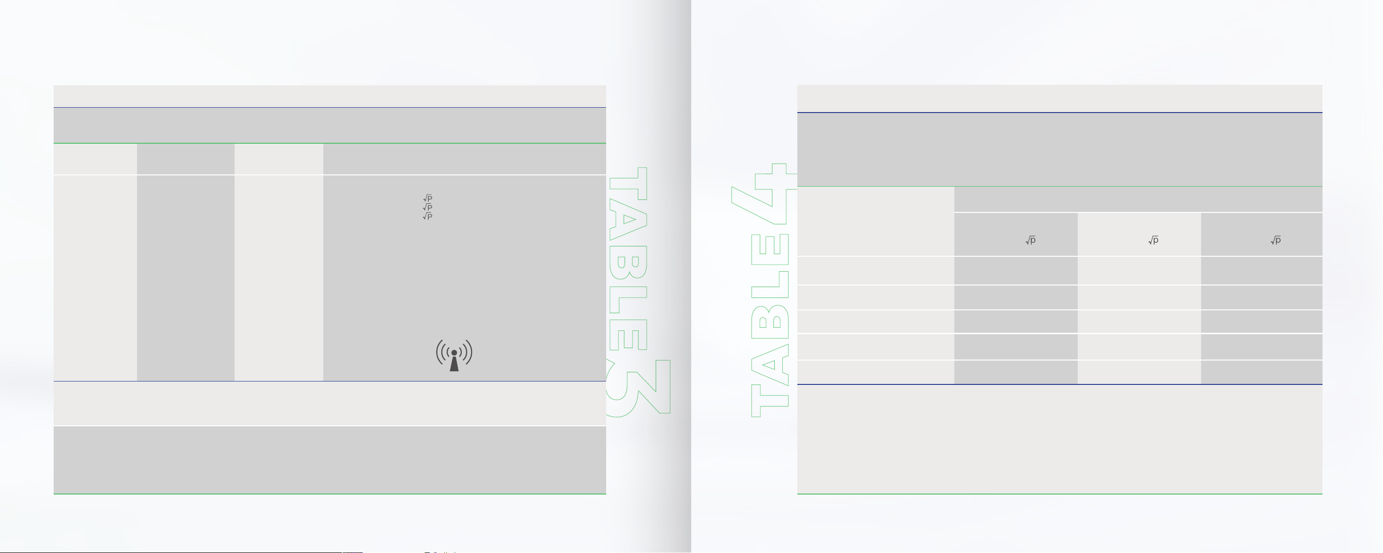
This product declarations to meet Table 1, Table 2, Table 3, Table 4of Contents.
24
26 27
Guidance and Manufacturer’s Declaration - Electromagnetic Immunity
The product intended for use in the electromagnetic environment specified below. The custom-
ers or users should ensure that it is used in such an environment.
Immunity test IEC60601 test level Electromagnetic environment- guidelinesCompliance level
Conducted RF
IEC 61000-4-6
Radiated RF
IEC 61000-4-3
3v(RMS)
150kHz~80MHz
3V/m
80MHz~2.5GHz
3V(RMS)
3V/m
Where P is the maximum output power rating of the transmitter
in watts (W) according to the transmitter manufacture.
‘d’ is the recommended separation distance in meter(m).
Filed strengths from fixed RF transmitters, as determined by an
electromagnetic site survey (notea), and each frequency range
(note b) should be less than the compliance level.
lnterference may occur in the vicinity of equipment marked with
the following symbol:
Recommended separation distance
d=1.2
d=1.2 80MHz~800MHz
d=2.3 800MHz~2.5GHz
Note 1: At 80 MHz and 800 MHz, the higher frequency range applies.
Note 2: These guidelines may not apply in all cases. Electromagnetic propagation is affected by absorption
and reflection from structures, object and people.
Note a: Flied strengths from fixed transmitters, such as base stations for radio (celular/cordless) telephones and land
mobile radios, amateur radio, AM and FM radio broadcast and TV broadcast cannot be predicte theoretically with
transmitter. To assess the electromagnetic environment fixed RF transmitters, electromagnetic site survey should be
considered. lf the measured field strength of the product is higher than the above RF compliance level, the product
should be observed to verify its normal operation.
Note b: Over the frequency range 150KHz~80MHz, field strengths should be less than 3V/m.
Rated maximum
output power of
transmitter W
0.01
0.1
1
10
100
150KHz~80MHz
d=1.2
0.12
0.38
1.2
3.8
12
80MHz~800MHz
d=1.2
0.12
0.38
1.2
3.8
12
800MHz~2.5GHz
d=2.3
0.23
0.73
2.3
7.3
23
Recommendation separation distances between the product and mobile RF communication equipment
This product is intended for use in an electromagnetic environment where radiated RF disturbances are
controlled. The costumer or the user of the product can help prevent electromagnetic interference by
maintaining a minimum distance between the portable or mobile RF communications equipment (transmit-
ters) and the product, according to the maximum output power of the communication equipment.
For transmitter rated at a maximum output power not listed above, the recommended separation distance d in
meters (m) can be estimated using the equation application to the frequency of the transmitter, where P is the
maximum output power rating of the transmitter in watts (W) according to the transmitter manufacturer, V1 is the
conducted RF compliance level and E1 is the RF radiated compliance level.
Note 1: At the 80 MHz and 800 MHz, the separation distance for the higher frequency range applies.
Note 2: These guidelines may not be suitable for all situations. Electromagnetic propagation is affected by the
absorption and reflection from structures, object and people.
Separation distance according to frequency of transmitter m