DEHUMIDIFIER
USER MANUAL (US STANDARD)
Thank you very much for choosing our brand's product.
To ensure your safety, proper, and efficient use of this
product, please read the instructions carefully and keep
them properly.
NINGBO AQUART ENVIRONMENTAL APPLIANCE CO.,LTD.


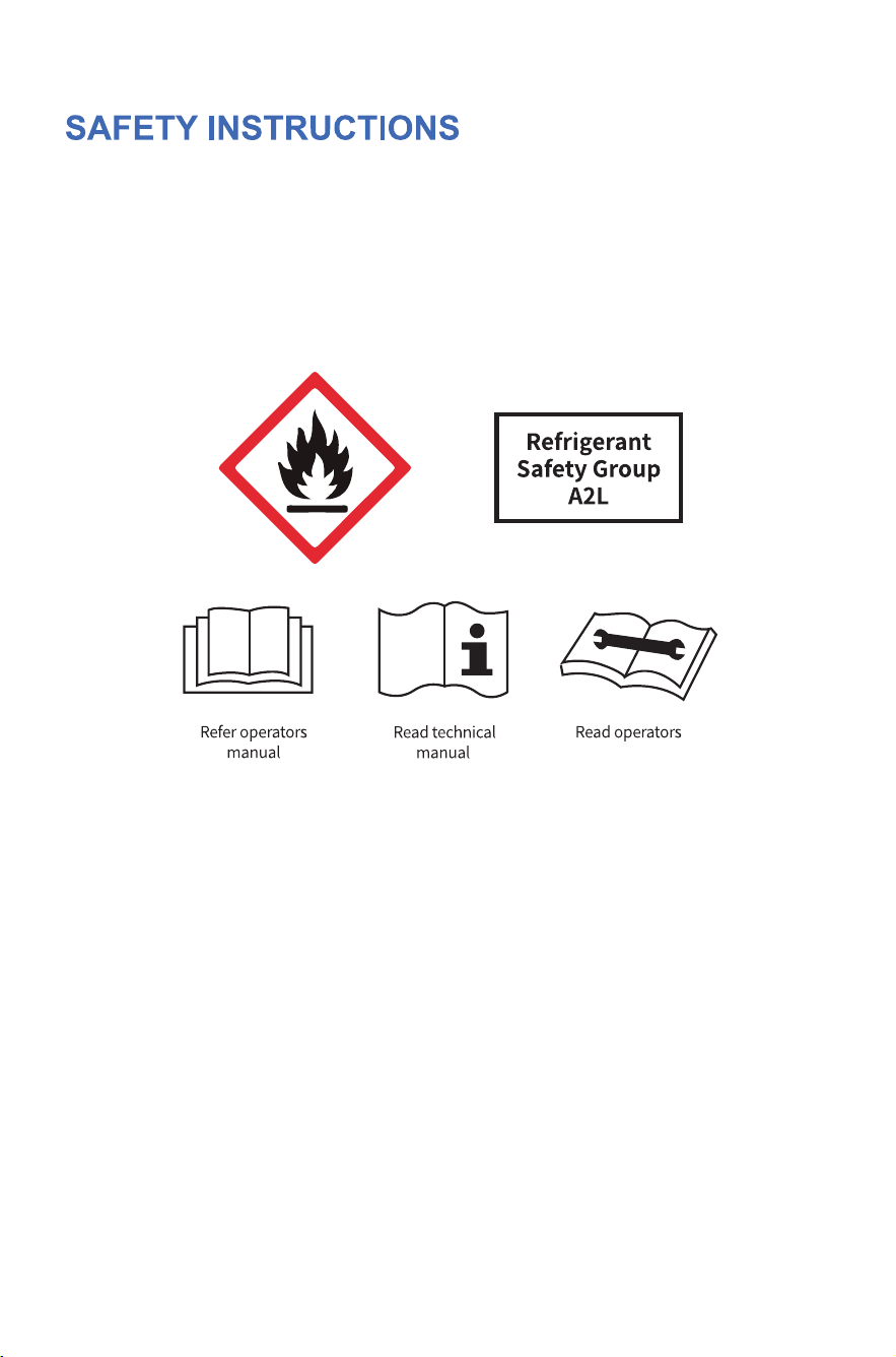
Safety Instructions
Product Structure
Installation Method Of
External Flange
Product Introduction
Control Panel Instructions
Precautions Troubleshooting
Special Reminder
Specifications
Function Description
01
07
09
10
12
14
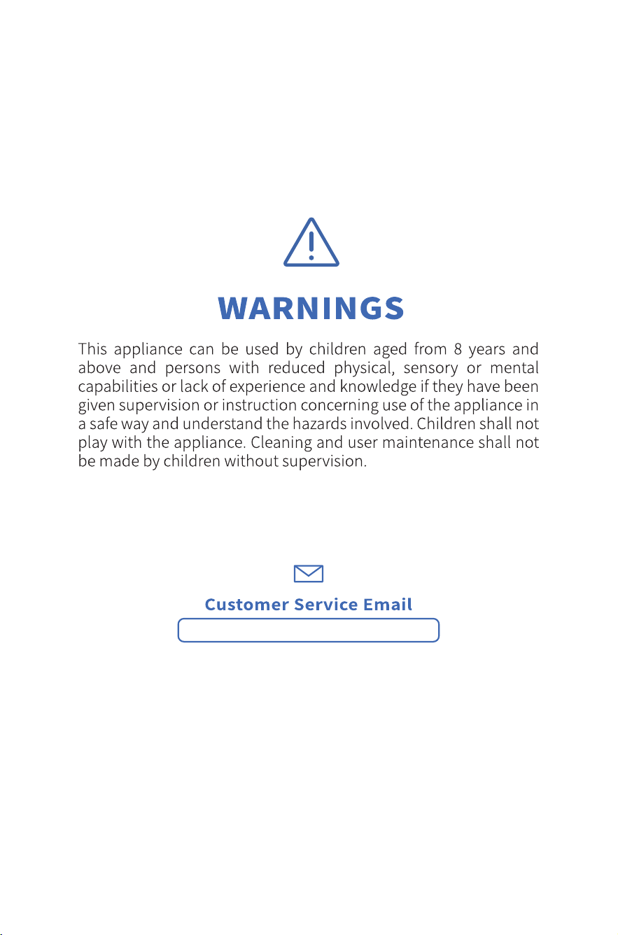
WARNING
Do not use means to accelerate the defrosting process or to clean, other than
those recommended by the manufacturer.
The appliance shall be stored in a room without continuously operating ignition
sources (for example: open flames, an operating gas appliance or an operating
electric heater.
Do not pierce or burn.
Be aware that refrigerants may not contain an odour.
●Qualification of workers
Every working procedure that affects safety means shall only be carried out by
competent persons.
Examples for such working procedures are:
• breaking into the refrigerating circuit;
• opening of sealed components;
• opening of ventilated enclosures.
●Checks to the area
Prior to beginning work on systems containing FLAMMABLE REFRIGERANTS,
safety checks are necessary to ensure that the risk of ignition is minimised.
●Work procedure
Work shall be undertaken under a controlled procedure so as to minimise the
risk of a flammable gas or vapour being present while the work is being
performed.
●General work area
All maintenance staff and others working in the local area shall be instructed on
the nature of work being carried out. Work in confined spaces shall be avoided.
01

02
●Checking for presence of refrigerant
The area shall be checked with an appropriate refrigerant detector prior to and
during work, to ensure the technician is aware of potentially toxic or flammable
atmospheres. Ensure that the leak detection equipment being used is suitable
for use with all applicable refrigerants, i.e. non-sparking, adequately sealed or
intrinsically safe.
●Presence of fire extinguisher
If any hot work is to be conducted on the refrigerating equipment or any associ-
ated parts, appropriate fire extinguishing equipment shall be available to hand.
Have a dry powder or CO2 fire extinguisher adjacent to the charging area.
●No ignition sources
No person carrying out work in relation to a REFRIGERATING SYSTEM which
involves exposing any pipe work shall use any sources of ignition in such a
manner that it may lead to the risk of fire or explosion. All possible ignition
sources, including cigarette smoking, should be kept sufficiently far away from
the site of installation, repairing, removing and disposal, during which refriger-
ant can possibly be released to the surrounding space. Prior to work taking
place, the area around the equipment is to be surveyed to make sure that there
are no flammable hazards or ignition risks. “No Smoking” signs shall be
displayed.
●Ventilated area
Ensure that the area is in the open or that it is adequately ventilated before
breaking into the system or conducting any hot work. A degree of ventilation
shall continue during the period that the work is carried out. The ventilation
should safely disperse any released refrigerant and preferably expel it externally
into the atmosphere.
●Checks to the refrigerating equipment
Where electrical components are being changed, they shall be fit for the purpose
and to the correct specification. At all times the manufacturer’s maintenance
and service guidelines shall be followed. If in doubt, consult the manufacturer’s
technical department for assistance.
The following checks shall be applied to installations using FLAMMABLE REFRIG-
ERANTS:
‒ the actual REFRIGERANT CHARGE is in accordance with the room size within
which the refrigerant containing parts are installed;
‒ the ventilation machinery and outlets are operating adequately and are not
obstructed;
‒ if an indirect refrigerating circuit is being used, the secondary circuit shall be
checked for the presence of refrigerant;
‒ marking to the equipment continues to be visible and legible. Markings and
signs that are illegible shall be corrected;
‒ refrigerating pipe or components are installed in a position where they are
unlikely to be exposed to any substance which may corrode refrigerant contain-
ing components, unless the components are constructed of materials which are
inherently resistant to being corroded or are suitably protected against being so
corroded.

03
●Checks to the refrigerating equipment
Where electrical components are being changed, they shall be fit for the purpose
and to the correct specification. At all times the manufacturer’s maintenance
and service guidelines shall be followed. If in doubt, consult the manufacturer’s
technical department for assistance.
The following checks shall be applied to installations using FLAMMABLE REFRIG-
ERANTS:
‒ the actual REFRIGERANT CHARGE is in accordance with the room size within
which the refrigerant containing parts are installed;
‒ the ventilation machinery and outlets are operating adequately and are not
obstructed;
‒ if an indirect refrigerating circuit is being used, the secondary circuit shall be
checked for the presence of refrigerant;
‒ marking to the equipment continues to be visible and legible. Markings and
signs that are illegible shall be corrected;
‒ refrigerating pipe or components are installed in a position where they are
unlikely to be exposed to any substance which may corrode refrigerant contain-
ing components, unless the components are constructed of materials which are
inherently resistant to being corroded or are suitably protected against being so
corroded.
●Checks to electrical devices
Repair and maintenance to electrical components shall include initial safety
checks and component inspection procedures. If a fault exists that could
compromise safety, then no electrical supply shall be connected to the circuit
until it is satisfactorily dealt with. If the fault cannot be corrected immediately
but it is necessary to continue operation, an adequate temporary solution shall
be used. This shall be reported to the owner of the equipment so all parties are
advised.
Initial safety checks shall include:
• that capacitors are discharged: this shall be done in a safe manner to avoid
possibility of sparking;
• that no live electrical components and wiring are exposed while charging,
recovering or purging the system;
• that there is continuity of earth bonding.
●Repairs to sealed components
Sealed electrical components shall be replaced.
●Repair to intrinsically safe components
Intrinsically safe components must be replaced.
●Cabling
Check that cabling will not be subject to wear, corrosion, excessive pressure,
vibration, sharp edges or any other adverse environmental effects. The check
shall also take into account the effects of aging or continual vibration from
sources such as compressors or fans.
●Detection of flammable refrigerants
Under no circumstances shall potential sources of ignition be used in the
searching for or detection of refrigerant leaks. A halide torch (or any other
detector using a naked flame) shall not be used.
The following leak detection methods are deemed acceptable for all refrigerant
systems.

04
Electronic leak detectors may be used to detect refrigerant leaks but, in the case
of FLAMMABLE REFRIGERANTS, the sensitivity may not be adequate, or may
need re-calibration. (Detection equipment shall be calibrated in a refriger-
ant-free area.) Ensure that the detector is not a potential source of ignition and is
suitable for the refrigerant used. Leak detection equipment shall be set at a
percentage of the LFL of the refrigerant and shall be calibrated to the refrigerant
employed, and the appropriate percentage of gas (25 % maximum) is confirmed.
Leak detection fluids are also suitable for use with most refrigerants but the use
of detergents containing chlorine shall be avoided as the chlorine may react with
the refrigerant and corrode the copper pipe-work.
If a leak is suspected, all naked flames shall be removed/extinguished.
If a leakage of refrigerant is found which requires brazing, all of the refrigerant
shall be recovered from the system, or isolated (by means of shut off valves) in a
part of the system remote from the leak. Removal of refrigerant shall be accord-
ing to Removal and evacuation.
●Removal and evacuation
When breaking into the refrigerant circuit to make repairs ‒ or for any other
purpose ‒
conventional procedures shall be used. However, for flammable refrigerants it is
important
that best practice be followed, since flammability is a consideration. The
following procedure shall be adhered to:
‒ safely remove refrigerant following local and national regulations;
‒ evacuate;
‒ purge the circuit with inert gas ;
‒ evacuate;
‒ continuously flush or purge with inert gas when using flame to open circuit;
and
‒ open the circuit.
The refrigerant charge shall be recovered into the correct recovery cylinders if
venting is
not allowed by local and national codes. For appliances containing flammable
refrigerants,
the system shall be purged with oxygen-free nitrogen to render the appliance
safe for
flammable refrigerants. This process might need to be repeated several times.
Compressed air or oxygen shall not be used for purging refrigerant systems.
For appliances containing flammable refrigerants, refrigerants purging shall be
achieved
by breaking the vacuum in the system with oxygen-free nitrogen and continuing
to fill until
the working pressure is achieved, then venting to atmosphere, and finally
pulling down to a
vacuum. This process shall be repeated until no refrigerant is within the system.
When the final oxygen-free nitrogen charge is used, the system shall be vented
down to atmospheric pressure to enable work to take place. The outlet for the
vacuum pump shall not be close to any potential ignition sources, and ventila-
tion shall be available.

05
●Charging procedures
In addition to conventional charging procedures, the following requirements
shall be followed.
• Ensure that contamination of different refrigerants does not occur when using
charging equipment. Hoses or lines shall be as short as possible to minimise the
amount of refrigerant contained in them.
• Cylinders shall be kept in an appropriate position according to the instructions.
• Ensure that the REFRIGERATING SYSTEM is earthed prior to charging the system
with refrigerant.
• Label the system when charging is complete (if not already).
• Extreme care shall be taken not to overfill the REFRIGERATING SYSTEM.
Prior to recharging the system, it shall be pressure-tested with the appropriate
purging gas. The system shall be leak-tested on completion of charging but prior
to commissioning. A follow up leak test shall be carried out prior to leaving the
site.
●Decommissioning
Before carrying out this procedure, it is essential that the technician is complete-
ly familiar with the equipment and all its detail. It is recommended good practice
that all refrigerants are recovered safely. Prior to the task being carried out, an oil
and refrigerant sample shall be taken in case analysis is required prior to re-use
of recovered refrigerant. It is essential that electrical power is available before
the task is commenced.
a) Become familiar with the equipment and its operation.
b) Isolate system electrically.
c) Before attempting the procedure, ensure that:
• mechanical handling equipment is available, if required, for handling refriger-
ant cylinders;
• all personal protective equipment is available and being used correctly;
• the recovery process is supervised at all times by a competent person;
• recovery equipment and cylinders conform to the appropriate standards.
d) Pump down refrigerant system, if possible.
e) If a vacuum is not possible, make a manifold so that refrigerant can be
removed from various parts of the system.
f) Make sure that cylinder is situated on the scales before recovery takes place.
g) Start the recovery machine and operate in accordance with instructions.
h) Do not overfill cylinders (no more than 80 % volume liquid charge).
i) Do not exceed the maximum working pressure of the cylinder, even temporari-
ly.
j) When the cylinders have been filled correctly and the process completed,
make sure that the cylinders and the equipment are removed from site promptly
and all isolation valves on the equipment are closed off.
k) Recovered refrigerant shall not be charged into another REFRIGERATING
SYSTEM unless it has been cleaned and checked.
●Labelling
Equipment shall be labelled stating that it has been de-commissioned and
emptied of refrigerant. The label shall be dated and signed. For appliances
containing FLAMMABLE REFRIGERANTS, ensure that there are labels on the
equipment stating the equipment contains FLAMMABLE REFRIGERANT.

06
●Recovery
When removing refrigerant from a system, either for servicing or decommission-
ing, it is recommended good practice that all refrigerants are removed safely.
When transferring refrigerant into cylinders, ensure that only appropriate
refrigerant recovery cylinders are employed. Ensure that the correct number of
cylinders for holding the total system charge is available. All cylinders to be used
are designated for the recovered refrigerant and labelled for that refrigerant (i.e.
special cylinders for the recovery of refrigerant). Cylinders shall be complete with
pressure-relief valve and associated shut-off valves in good working order.
Empty recovery cylinders are evacuated and, if possible, cooled before recovery
occurs.
The recovery equipment shall be in good working order with a set of instructions
concerning the equipment that is at hand and shall be suitable for the recovery
of the
flammable refrigerant. If in doubt, the manufacturer should be consulted. In
addition, a set
of calibrated weighing scales shall be available and in good working order. Hoses
shall be
complete with leak-free disconnect couplings and in good condition.
The recovered refrigerant shall be processed according to local legislation in the
correct
recovery cylinder, and the relevant waste transfer note arranged. Do not mix
refrigerants in
recovery units and especially not in cylinders.
If compressors or compressor oils are to be removed, ensure that they have been
evacuated to an acceptable level to make certain that flammable refrigerant
does not
remain within the lubricant. The compressor body shall not be heated by an
open flame or
other ignition sources to accelerate this process. When oil is drained from a
system, it
shall be carried out safely.
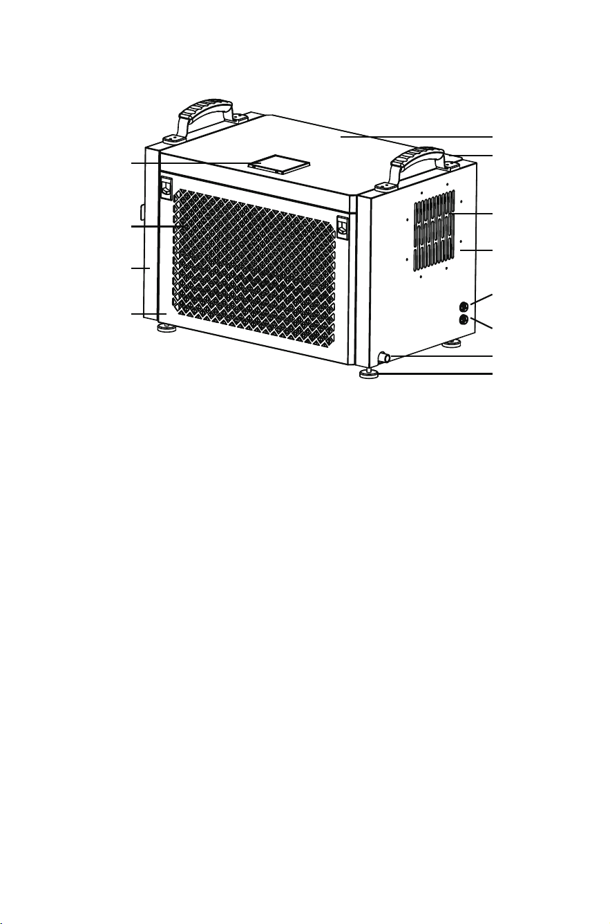
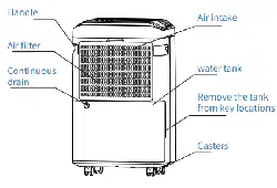
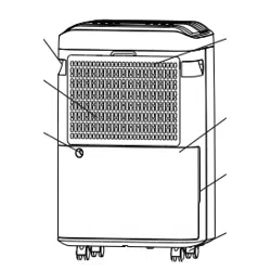
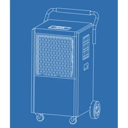
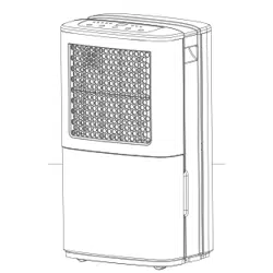
PRODUCT STRUCTURE
INSTALLATION METHOD OF EXTERNAL FLANGE
Control Panel
Air Inlet
Front Shell
Right Side
Panel
Tectum
Handle
Air Outlet
Left Side
Panel
Screen
Interface
Water Full
Interface
Outfall
Holder
1.This machine is equipped with an external flange(an external flange can also
be omitted according to customer's demands). The flange parts are inside the
machine.
The specific operation process is as follows:
Unscrew the screws of the machine's rear shell (Figure 1)(a total of 3 pcs),open
the rear shell(Figure 2), take out the external flange, and fix the rear
shell. At this point, fix the flange joint (Figure 3) on the left plate (a total of 6
pieces).
Reminder
1. After the entire machine is installed, please let it stand
for 2 hours before turning it on for use.
2. The drainage method of this machine adopts direct drainage, or it can be
connected to the drainage pipe for drainage. The height of the drainage pipe
outlet must not exceed the height of the water tank.
07
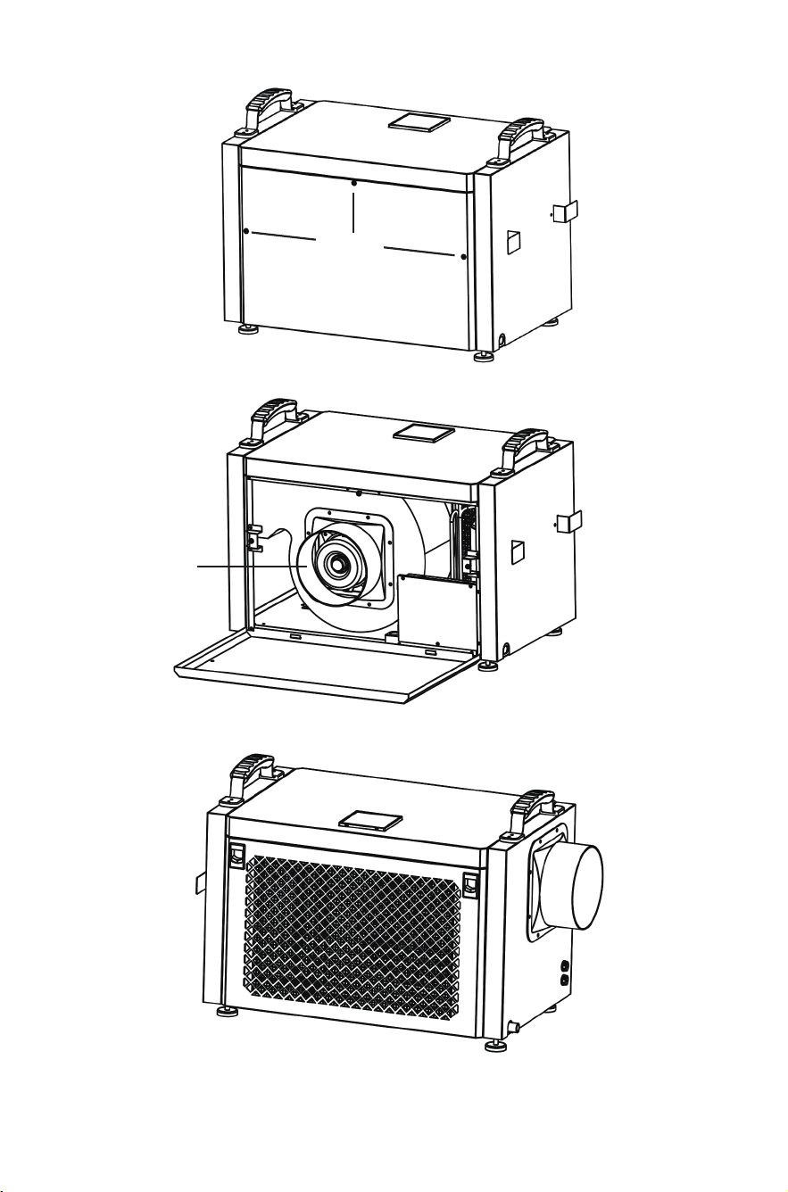
Screw
External
flange
Figure 1
Figure 2
Figure 3
08
PRODUCT INTRODUCTION
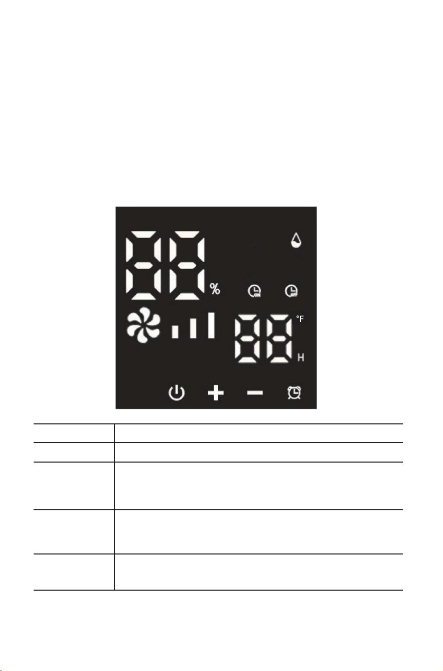
CONTROL PANEL INSTRUCTIONS
The dehumidifier is used to reduce the air humidity in the installed space to
make it suitable for people's living and item storage. Our dehumidifier uses a
branded compressor and micro-computer humidity control. Humidity display is
clear and intuitive. The appearance is beautiful, the performance is superior
and the operation is simple. It is widely used in scientific research, industry,
medical and health, instru-mentation, commodity storage, underground
engineering, computer rooms, data rooms, archives, warehouses, baths, etc., to
prevent instruments, meters, computers, telecommunication materials,
commodities, and materials from moisture, corrosion, and mildew.
KEYPAD
DESCRIPTION
POWER
+
-
MODE
Press once to toggle between on and off.
Adjust different settings in different states.
1.Increase humidity setting value (range RH10%~95%)
2.Increase timer setting value (range 00~24 hours)
Adjust different settings in different states.
1.Decrease humidity setting value (range RH10%~95%)
2.Decrease timer setting value (range 00~24 hours)
Press briefly once to cycle through setting timer and
humidity adjustment functions and exit.
09

FUNCTION DESCRIPTION
1、Humidity Control:
When the set humidity is reached, the fan still operate and compressor stop.
When the humidity exceeds the set level, both the fan and compressor operate.
Notes
●When the humidity setting is at the lowest value, it defaults to continuous
dehu- midification mode.
If the humidity sensor fails, it switches to continuous dehumidification mode.
●If the coil sensor fails, it switches to a fixed timed defrost mode (see Defrost
Method).
●Upon startup, the compressor delays 3 seconds, and upon shutdown, the fan
delays 3 seconds.
●When the humidity drops to the condition where the compressor stops, the
fan operates normally.
●Power outage memory: If the system suddenly encounters a power outage
while working, it automatically stores the current operating state. When
powered on again, the system will automatically enter the previous operating
state and continue opera- tion.
2、Detailed Function Description:
●After the first power connection, press the power button to enter the startup
mode. The humidity defaults to 50%RH, displaying the current humidity and
temperature. The entire machine operates with both the compressor and fan
starting.
●Press the Mode button to enter the timer setting function. Press “+”or “-”to
set the shutdown timer. The timer indicator on the screen will flash.Adjust the
time with “+”or “-”(range 0~24H). If no operation is made within 5 seconds,
the system automatically executes the current timer function setting.
● Press the Mode button again to enter the humidity adjustment function.-
Press “+” or “-”to set the humidity (range 10%-95%-CO). The “CO”mode is a
forced dehumidi- fication mode, regardless of temperature and humidity, with
the fan and compressor continuously operating.
10

4、Timer Switch Instructions:
● In the on state, a shutdown timer can be set. In the off state, a startup timer
can be set. Setting both simultaneously enters a cyclic timer state.
● Timer Startup Setting: In the off state, press the “mode”button. The “timer
on” icon flashes, and the time display area flashes the set time. Adjust the time
with “+” or “-”.The buzzer beeps once for each press. Holding the button for 2
seconds allows continuous adjustment. After 10 seconds without operation,
the machine accepts the setting, and the “timer on”icon flashes (range 0~
24H).
● Timer Shutdown Setting: In the on state, press the “Mode”button. The “timer
off”icon flashes, and the time display area flashes the set time. Adjust the time
with “+”or “-”. The buzzer beeps once for each press. Holding the button for 2
seconds allows continuous adjustment. After 10 seconds without operation, the
machine accepts the setting, and the “timer off”icon flashes (range 0~24H).
3、Defrost Method:
Defrosting Method Description
Automatic Defrost Sensor is normal
Timed Defrost
Conditions:
When the compressor runs
continuously for 30 minutes and
the coil temperature is ≦ 30℉, it
enters defrost mode. During
defrost, the compressor stops and
the fan continues to run.
In defrost mode, the system defrosts for 8 minutes.
After the time is up, it exits defrost mode.
11

PRECAUTIONS TROUBLESHOOTING
Cause Analysis SolutionMalfunction
No power display
Power outage or socket
without power
Fuse on control board
blown
Transformer on control
board damaged
Power display
Entire machine is
defrosting
Inlet/outlet is obstructed
Windows are open
Room temperature is
too low
Uneven ground
Machine not placed
stably
Machine is tilted
Drain pipe/drain outlet
blocked
Check if the power is normal
Power plug not inserted
properly
Insert the power plug into the
socket
Replace the fuse
Replace the transformer
Wait for defrost to finish
Environment humidity
lower than set humidity
Reset as needed
Remove obstruction
Close doors and windows
Do not use
Reposition the machine
Reposition stably
Level the machine
Remove front panel and clean
blockage
Machine won’t
run
Poor dehumi-
dification
Noise
Noise
1.If the dehumidifier malfunctions, immediately cut off the power and check
the following items:
12

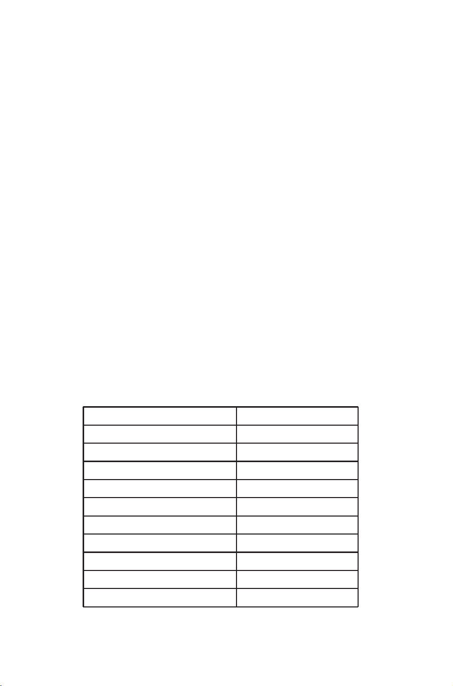
Error Codes
2.If the above checks do not resolve the issue, contact the manufacturer or
dealer directly. Do not disassemble the machine yourself.
3.During operation, the sound of refrigerant circulating is normal. The exhaust
air outlet discharges warm air, causing a 34-37℉ increase in room tempera-
ture, which is normal.
4.When moving, do not tilt the machine more than 45 degrees to prevent
compressor damage.
5.The machine operates at 41-95℉ .
6.When the room temperature is below 50℉ and absolute humidity is very low,
using the dehumidifier may not be necessary.
7. Keep the air inlet and outlet at least 1 meter away from walls or obstructions
to avoid affecting the dehumidification effect.
8.Dust accumulation on the air filter will affect dehumidification and may
cause malfunctions. Clean it regularly, at least once a month. In dusty environ-
ments, clean weekly or even daily. Gently tap the filter or use a vacuum cleaner
to remove dust. For severe dust, rinse with water and dry before reinstalling.
9. If there is a fault code during the operation of the machine, please shut down
and stop running. Immediately report to the after-sales staff for repair
10. Continuous 24-hour operation of the machine will affect its service life. It is
recom- mended to stop the machine for 2 hours after every 10 hours of
operation. If the user has special requirements, the machine must be operated
24 hours a day and must be supervised by dedicated personnel. Otherwise, in
case of accidents, our company will not be held responsible.
Cause Analysis SolutionMalfunction
Coil sensor fault
Switch to timed defrost,
cancel system fault function,
recoverable
Temperature sensor fault
Humidity sensor fault
Replace temperature sensor
Replace humidity sensor
E1
E2
E3
13
SPECIAL REMINDER
SPECIFICATIONS
1.Humidity sensors are precision components that can cause sensor failure
when used in environments with strong corrosive gases and large dust.
2. This machine does not have explosion-proof function and is strictly prohibit-
ed from use in environments with special requirements such as flammable,
explosive gases, dust, chemical products, and biological products.
3. If used in the above environment, causing damage to the machine is not
covered by the warranty.
4. When installing this machine, be sure to take grounding protection measures
to ensure safe use.
5. After running the machine for a period of time, water will be discharged.
Please pay attention to the treatment of drainage.
6.To reduce malfunctions and extend service life, do not use brute force when
operat- ing buttons.
7. The humidity sensor may deviate slightly from the actual humidity due to
its location, environment, and temperature, which is a normal phenomenon.
8.During machine operation, the cooled air will be discharged through the
condenser after drying, and the outlet temperature is higher than the ambient
temperature. It is normal to discharge hot air.
9. The dehumidification capacity is related to the ambient temperature and
humidi- ty. High temperature and humidity result in a large dehumidification
capacity; Under low temperature or low humidity conditions, the dehumidifi-
cation capacity will decrease, which is a normal phenomenon.
Specification Table:
MODEL
Power Supply
Rated Power
Rated Current
Low Side Pressure
High Side Pressure
Refrigerant:
Motor Compressor
Product Size
Net Weight
Applicable Temperature
AP60-2401
AC 115V/60Hz
520W
4.7 A
290psig
650psig
R32/(9.7oz)(275g)
RLA:5.52A ; LRA:27A
25.79*13.78*14.57 in
59.5 lb
41-95℉
14