
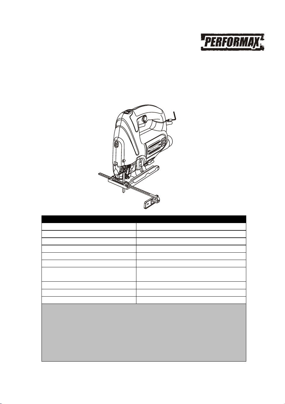
ORBITAL JIGSAW WITH LASER
AND LED WORK LIGHT
241-0992
Owner’s Manual
PRODUCT SPECIFICATIONS
Rating:
120V, 60Hz, AC
Amperes:
6.0 AMP
Variable speed:
800–3,000 SPM (no load)
Stroke length:
3/4"
Blade change system:
Tool free
Blade types:
"T" or "U" shank
Cutting depth @ 90°:
Wood: 3 1/8"
Metal: 5/16"
Orbital settings:
4 (including neutral)
Base plate bevel:
0–45°
Weight:
5.1 lb
Need Assistance?
Call us on our toll free customer support line:
1-866-349-8665
Technical questions
Replacement parts
Parts missing from package

2
Product specifications ………….………………………………………………………………...
1
Table of contents ……………………………………………………………………...………....
2
General safety warnings ……………………………………………………………..………....
3–4
Eye, ear & lung protection ……………………………………………………………………....
3–4
Electrical safety ……………………………………………………………………….………....
4
Power tool safety ……………………………………………………………………...………....
5–6
General safety rules …………………………………………………………………..………....
5
Work area ………………………………………………………………….…………..………....
5
Electrical safety ……………………………………………………………………….………....
5
Personal safety ………………………………………………………………………..………....
5–6
Power tool use and care.……………………………………………………………..………....
6
Service …………………………………………………………………………………………....
6
Specific safety rules …………………………………………………………………..………....
7
Extension cord safety ………………………………………………………….……..………....
8
Symbols ………………………………………………………………………………..………....
9
Know your jigsaw …………………………………………………………….............………....
10
Assembly and operating ……………………………………………………………..………....
11–17
Installing a blade ………………………………………………………………………………....
11
Removing a blade …………………………………………………………………….………....
11
Hex key storage ……………………………………………………………………….………....
11
Installing the edge guide ……………………………………………………………..………....
11–12
Setting the bevel angle ……………………………………………………………….………....
12
Setting the orbital cutting angle ……………………………………………………..……….....
13
Laser / LED worklight ……………………………………………………………………………
13
Variable speed control wheel ……………………………………………………………………
13–14
Trigger switch ………………………………………………………………………………….....
14
Lock-on button ……………………………………………………………………….………......
14
Installing the vacuum adaptor ……………………………………………………………….....
14
Vacuum port switch …………………………………………………………………………......
14–15
Materials you can cut ………………………………………………………………………...….
15
General cutting ………………………………………………………………………………......
15–16
Bevel cutting …………………………………………………………………………………......
16
Plunge cutting ………………………………………………………………………………...….
16
Metal cutting ………………………………………………………………………….………......
17
Maintenance ………………………………………………………………………….……….....
18
Exploded view ………………………………………………………………………………...….
19
Parts list ……………………………………………………………………………….……….....
20–21
Warranty ……………………………………………………………………….……………...….
22
TABLE OF CONTENTS

3
EYE, EAR & LUNG PROTECTION
SAVE THESE INSTRUCTIONS FOR REFERENCE
This instruction manual includes the following:
General Safety Rules
Specific Safety Rules and Symbols
Functional Description
Assembly
Operation
Maintenance
Accessories
WARNING: Before using this tool or any of its accessories, read this
manual and follow all Safety Rules and Operating Instructions. The important
precautions, safeguards and instructions appearing in this manual are not
meant to cover all possible situations. It must be understood that common
sense and caution are factors which cannot be built into the product.
!
!
ALWAYS WEAR EYE PROTECTION THAT CONFORMS WITH CSA
REQUIREMENTS or ANSI SAFETY STANDARD Z87.1
FLYING DEBRIS can cause permanent eye damage. Prescription
eyeglasses ARE NOT a replacement for proper eye protection.
WARNING: Non-compliant eyewear can cause serious injury if
broken during the operation of a power tool.
WARNING: Use hearing protection, particularly during extended
periods of operation of the tool, or if the operation is noisy.
!
SAVE THESE INSTRUCTIONS FOR REFERENCE
GENERAL SAFETY WARNINGS

4
ELECTRICAL SAFETY
WEAR A DUST MASK THAT IS DESIGNED TO BE USED WHEN
OPERATING A POWER TOOL IN A DUSTY ENVIRONMENT.
WARNING: Dust that is created by power sanding, sawing, grinding,
drilling, and other construction activities may contain chemicals that are
known to cause cancer, birth defects, or other genetic abnormalities. These
chemicals include:
Lead from lead-based paints
Crystalline silica from bricks, cement, and other masonry products
Arsenic and chromium from chemically treated lumber
The level of risk from exposure to these chemicals varies, according to how
often this type of work is performed. In order to reduce exposure to these
chemicals, work in a well-ventilated area, and use approved safety
equipment, such as a dust mask that is specifically designed to filter out
microscopic particles.
!
WARNING: To avoid electrical hazards, fire hazards or damage to the
tool, use proper circuit protection.
This tool is wired at the factory for 120 V AC operation. It must be
connected to a 120 V AC, 15 A circuit that is protected by a time-delayed
fuse or circuit breaker. To avoid shock or fire, replace power cord
immediately if it is worn, cut or damaged in any way.
SAVE THESE INSTRUCTIONS FOR REFERENCE
GENERAL SAFETY WARNINGS

5
WARNING: Read all safety warnings
and instructions. Failure to follow the
warnings and instructions may result in
electric shock, fire and/or serious injury.
Save all warnings and instructions for
future reference.
Work area safety
Keep work area clean and well lit. Cluttered
or dark areas invite accidents.
Do not operate power tools in explosive
atmospheres, such as in the presence of
flammable liquids, gases or dust. Power
tools create sparks which may ignite the dust
or fumes.
Keep children and bystanders away while
operating a power tool. Distractions can
cause you to lose control.
Electrical safety
Power tool plugs must match the outlet.
Never modify the plug in any way. Do not
use any adapter plugs with earthed
(grounded) power tools. Unmodified plugs
and matching outlets will reduce risk of
electric shock.
Avoid body contact with earthed or
grounded surfaces such as pipes,
radiators, ranges and refrigerators. There
is an increased risk of electric shock if your
body is earthed or grounded.
Do not expose power tools to rain or wet
conditions. Water entering a power tool will
increase the risk of electric shock.
Do not abuse the cord. Never use the cord
for carrying, pulling or unplugging the
power tool. Keep cord away from heat, oil,
sharp edges or moving parts. Damaged or
entangled cords increase the risk of electric
shock.
When operating a power tool outdoors,
use an extension cord suitable for outdoor
use. Use of a cord suitable for outdoor use
reduces the risk of electric shock.
If operating a power tool in a damp
location is unavoidable, use a residual
current device (RCD) protected supply.
Use of a ground fault circuit interrupter (GFCI)
reduces the risk of electric shock.
Personal safety
Stay alert, watch what you are doing and
use common sense when operating a
power tool. Do not use a power tool while
you are tired or under the influence of
drugs, alcohol or medication. A moment of
inattention while operating power tools may
result in serious personal injury.
Use personal protective equipment.
Always wear eye protection. Protective
equipment such as dust mask, non-skid
safety shoes, hard hat, or hearing protection
used for appropriate conditions will reduce
personal injuries.
Prevent unintentional starting. Ensure the
switch is in the off-position before
connecting to power source and/or battery
pack, picking up or carrying the tool.
Carrying power tools with your finger on the
switch or energizing power tools that have the
switch on invites accidents.
Remove any adjusting key or wrench
before turning the power tool on. A wrench
or a key left attached to a rotating part of the
power tool may result in personal injury.
Do not overreach. Keep proper footing
and balance at all times. This enables better
control of the power tool in unexpected
situations.
Dress properly. Do not wear loose
clothing or jewelry. Keep your hair,
clothing and gloves away from moving
parts. Loose clothes, jewelry or long hair can
be caught in moving parts.
If devices are provided for the connection
of dust extraction and collection facilities,
ensure these are connected and properly
used. Use of dust collection can reduce dust-
related hazards.
!
POWER TOOL SAFETY

6
PERSONAL SAFETY – cont’d
Power tool use and care
Do not force the power tool. Use the
correct power tool for your application.
The correct power tool will do the job better
and safer at the rate for which it was
designed.
Do not use the power tool if the switch
does not turn it on and off. Any power tool
that cannot be controlled with the switch is
dangerous and must be repaired.
Disconnect the plug from the power
source and/or the battery pack from the
power tool before making any
adjustments, changing accessories, or
storing power tools. Such preventive safety
measures reduce the risk of starting the
power tool accidentally.
Store idle power tools out of the reach of
children and do not allow persons
unfamiliar with the power tool or these
instructions to operate the power tool.
Power tools are dangerous in the hands of
untrained users.
Maintain power tools. Check for
misalignment or binding of moving parts,
breakage of parts and any other condition
that may affect the power tool’s operation.
If damaged, have the power tool repaired
before use. Many accidents are caused by
poorly maintained power tools.
Keep cutting tools sharp and clean.
Properly maintained cutting tools with sharp
cutting edges are less likely to bind and are
easier to control.
Use the power tool, accessories and tool
bits etc. in accordance with these
instructions, taking into account the
working conditions and the work to be
performed. Use of the power tool for
operations different from those intended could
result in a hazardous situation.
Hold power tool by insulated gripping
surfaces when performing an operation
where the cutting tool may contact hidden
wiring or its own cord. Contact with a
"live" wire will make exposed metal parts of
the tool "live" and shock the operator.
Use clamps or another practical way to
secure and support the workpiece to a
stable platform. Holding the work by hand or
against your body leaves it unstable and
may lead to loss of control.
Service
Have your power tool serviced by a
qualified repair person using only
identical replacement parts. This will
ensure that the safety of the power tool is
maintained.
POWER TOOL SAFETY

7
WARNING: Know your jigsaw. Do not
plug in the jigsaw until you have read and
understand this Instruction Manual. Learn
the tool’s applications and limitations, as
well as the specific potential hazards
related to this tool. Following this rule will
reduce the risk of electric shock, fire, or
serious injury.
Always wear eye protection.
Any power tool can throw
foreign objects into your eyes
and cause permanent eye
damage. ALWAYS wear safety goggles (not
glasses) that comply with ANSI safety
standard Z87.1. Everyday glasses have only
impact resistant lenses. They ARE NOT
safety glasses.
WARNING: Glasses or goggles not in
compliance with ANSI Z87.1 could cause
serious injury when they break.
Always wear safety goggles, hearing
protection and a dust mask. Use only in well-
ventilated areas. Using personal safety
devices and working in a safe environment
reduces the risk of injury.
Hold the tool by insulated gripping surfaces
when performing an operation where the saw
blade may contact hidden wiring or its own
cord. Contact with a "live" wire will make
exposed metal parts of the tool "live" and
shock the operator.
Always make sure the work surface is free of
nails and other foreign objects. Cutting into a
nail can cause the blade and the tool to jump
and damage the blade.
Never hold the workpiece in one hand and
the tool in the other hand when sawing.
Never place your hands near or below the
cutting surface. Clamping the material and
guiding the tool with both hands is much
safer.
Never lay the workpiece on hard surfaces like
concrete, stone, etc. The protruding blade
may cause the tool to jump.
DANGER: Always remove the plug from
the power source when changing the blade
and when making adjustments.
Use only "U" or "T" shank blades that are
designed specifically for jigsaw use. Never
use a broken blade, as it will not be securely
held in the tool.
After changing a blade, make sure the blade
is securely held in the blade holder. Loose
blades will be violently thrown.
Never touch the blade during or immediately
after use. After use, the blade is too hot to be
touched by bare hands.
Never use dull or damaged blades. Sharp
blades must be handled with care. Damaged
blades can snap during use. Dull blades
require more force to cut the workpiece,
possibly causing the blade to break.
Always use the straight reciprocating action
when cutting metal. Blades will last longer
and will be less likely to break.
SPECIFIC SAFETY RULES
!
!
!

8
WARNING: Keep the extension cord
clear of the working area. Position the cord
so it will not get caught on the workpiece,
tools or any other obstructions while you are
working with the power tool.
Make sure any extension cord used with this
tool is in good condition. When using an
extension cord, be sure to use one of heavy
enough gauge to carry the current the tool will
draw. An undersized cord will cause a drop in
line voltage resulting in loss of power and
overheating.
The table at right shows the correct size to
use according to cord length and nameplate
ampere rating. If in doubt, use the next
heavier gauge. The smaller the gauge
number the heavier the cord.
Be sure your extension cord is properly wired
and in good condition. Always replace a
damaged extension cord or have it repaired
by a qualified electrician before using it.
Protect your extension cord from sharp
objects, excessive heat and damp or wet
areas.
Use a separate electrical circuit for your
power tools. This circuit must not be less
than 14 gauge wire and should be protected
with either a 15 AMP time delayed fuse or
circuit breaker. Before connecting the power
tool to the power source, make sure the
switch is in the OFF position and the power
source is the same as indicated on the
nameplate. Running at lower voltage will
damage the motor.
WARNING: Repair or replace
damaged or worn extension cords
immediately.
Select the appropriate extension cord
gauge and length using the chart below.
When operating a power tool outdoors,
use an outdoor extension cord marked
“W-A” or “W”. These cords are rated for
outdoor use and reduce the risk of electric
shock.
WARNING: Keep the extension cord
clear of the working area. Position the
cord so it will not get caught on the
workpiece, tools or any other obstructions
while you are working with the power tool.
MINIMUM GAUGE (AWG)
EXTENSION CORDS (120V use only)
Amperage
rating
Total length
More
than
Not
more
than
25'
(7.5 m)
50'
(15 m)
100'
(30 m)
150'
(45 m)
0
6
18
16
16
14
6
10
18
16
14
12
10
12
16
16
14
12
12
16
14
12
Not Applicable
!
!
!
EXTENSION CORD SAFETY
9
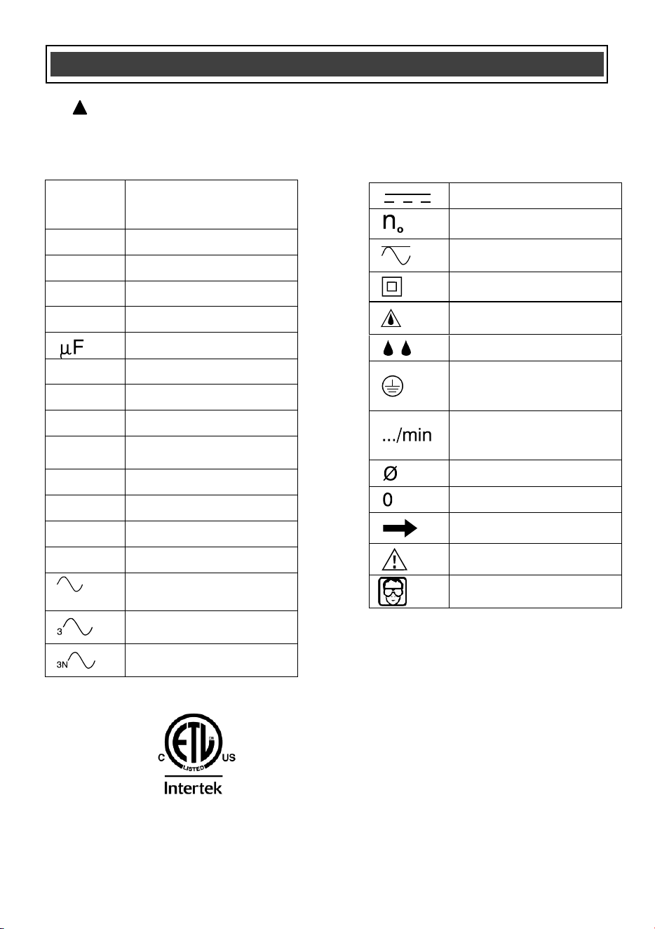
This symbol designates that this tool is
listed with U.S. requirements by
ETL Testing Laboratories, Inc.
Conforms to UL Std. 60745-1 and
60745-2-11.
3042597
JD2902LU
LISTED
V
Volts
A
Amperes
Hz
Hertz
W
Watts
kW
Kilowatts
Microfarads
L
Liters
kg
Kilograms
H
Hours
N/cm
2
Newtons per square
centimeter
Pa
Pascals
OPM
Oscillations per minute
Min
Minutes
S
Seconds
or a.c.
Alternating current
Three-phase alternating
current
Three-phase alternating
current with neutral
Direct current
No load speed
Alternating or direct
current
Class II construction
Splash-proof
construction
Watertight construction
Protective grounding at
grounding terminal,
Class I tools
Revolutions or
reciprocations per
minute
Diameter
Off position
Arrow
Warning symbol
Wear your safety
glasses
WARNING: Some of the following symbols may appear on the jigsaw. Study these
symbols and learn their meaning. Proper interpretation of these symbols will allow for
more efficient and safer operation of this tool.
!
SYMBOLS
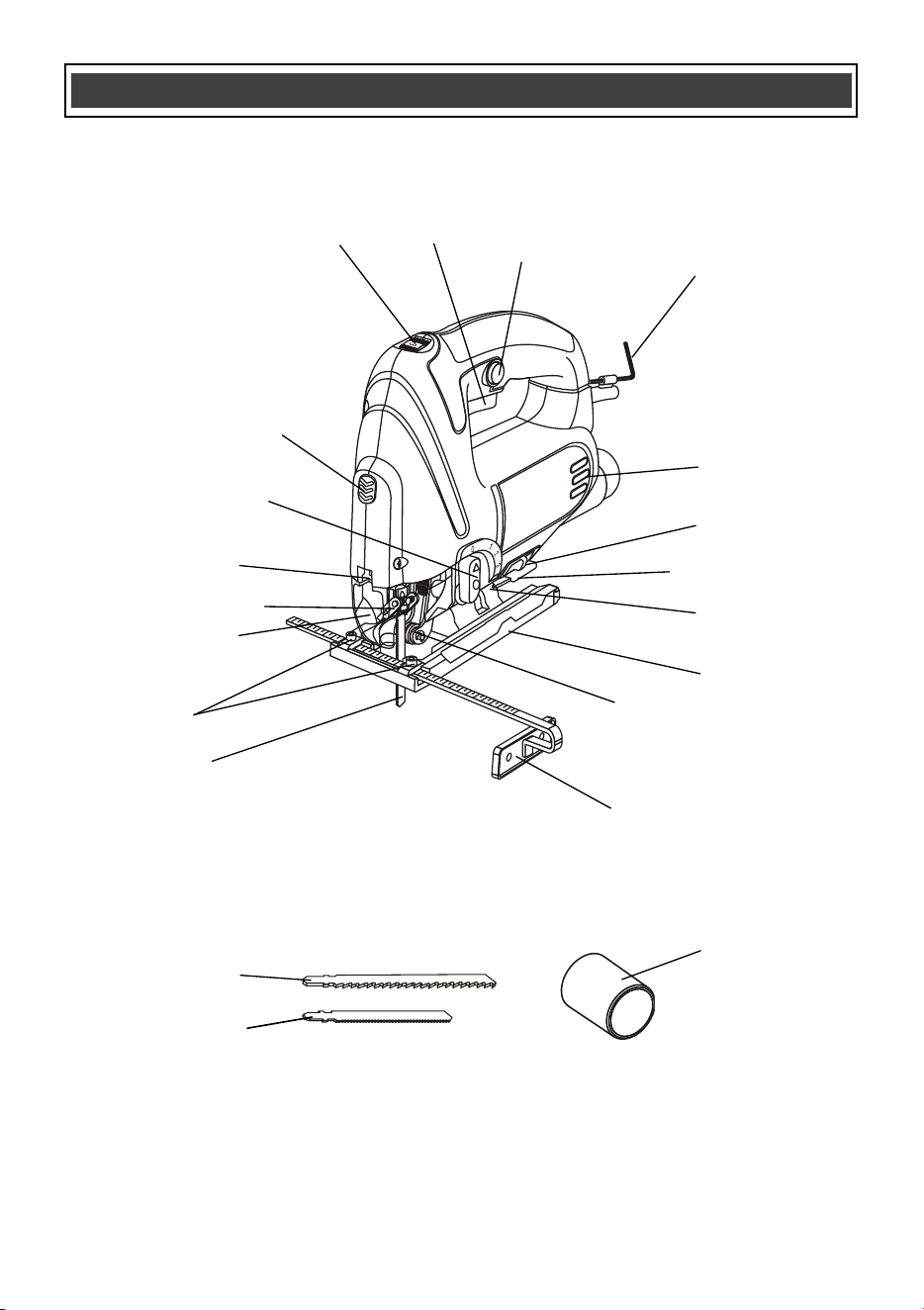
10
KNOW YOUR JIGSAW
Trigger
switch
Lock-on
button
Blade holder
Laser / LED
switch
Blade guide
roller
Chip guard
Tilting sole
plate
Motor vents
Hex key
Orbital action
lever
Bevel angle
scale
Edge guide
Speed control
wheel
Sawdust
deflector switch
Metal cutting
blade
Edge guide
screws
Laser
Bevel angle quick
release lever
Vacuum
adaptor
Wood cutting
blade
Metal cutting
blade
11
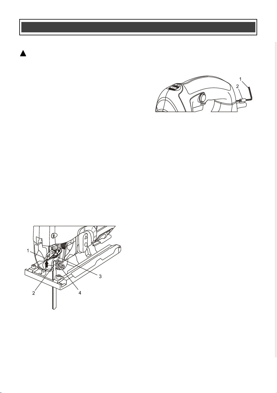
INSTALLING A BLADE
WARNING: Always remove the plug
from the power source before installing or
removing a blade or adjusting the jigsaw
in any way.
1. To install a blade in the jigsaw, push
upward on the blade locking lever (1)
(Fig. 1).
2. Insert the appropriate blade (2) into the
blade slot (3) as far as it will go.
NOTE: Make sure the rear edge of the blade
is nested in the blade guide roller (4).
3. Release the blade-locking lever.
NOTE: The blade will automatically be locked
into the blade holder. Pull outward on the
blade to ensure it is properly locked into the
blade holder.
REMOVING A BLADE
To remove a blade, simply push upward on
the blade locking lever and remove the blade
from the blade holder.
HEX KEY STORAGE
The 1/8" (3 mm) hex key (1) for adjusting the
edge guide is stored in power cord holder (2)
at the rear of the jigsaw (Fig. 2).
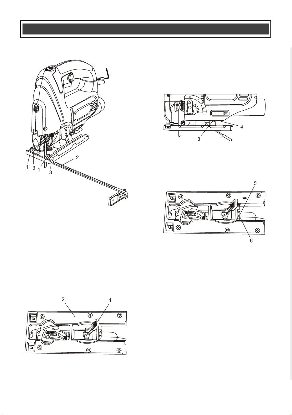
INSTALLING THE EDGE GUIDE
This jigsaw is equipped with an edge guide
that will assist in cutting narrow edges from a
workpiece.
1. Loosen the two edge guide mounting
screws (1) (Fig. 3).
2. Insert the edge guide (2) into the edge
guide mounting slots (3) in the sole
plate.
3. Set the edge guide at the desired
distance from the blade and lock it into
place by tightening the edge guide
mounting screws.
NOTE: Tighten the screws using the 1/8"
(3 mm) hex key supplied.
4. Make a test cut on a scrap workpiece to
ensure the edge guide is set correctly.
5. Adjust the edge guide as required.
ASSEMBLY AND OPERATION
!
Fig. 1
Fig. 2
12
INSTALLING THE EDGE GUIDE – cont’d
SETTING THE BEVEL CUTTING ANGLE
Bevel cutting angles may be adjusted from 0°
to 45° either left or right. To adjust the bevel
angle:
1. Lift the bevel angle quick release lever
(1) out of the sole plate (2) until the sole
plate can be rotated (Fig. 4).
2. Bevel angles (3) are marked on a scale
located on the side of the base (Fig. 5).
3. Slide the base toward the front of the
jigsaw and align the bevel angle with the
edge of the base (4).
4. Slide the base backward to engage the
bevel angle slot (5) with the indexing pin
(6) (Fig. 6)
NOTES:
a) Use a protractor to check the bevel angle
between the blade and the base.
b) To set the bevel angle at intermediate
angles, do not slide the base backward.
5. Once the desired bevel angle is
obtained, lock the base by pressing the
quick release lever into the sole plate.
NOTE: If the quick release lever fails to
firmly lock the base in the desired
position, release the lever, rotate it 1/2
turn clockwise and lock the base again.
6. Make a test cut in a scrap workpiece and
measure the bevel angle. Adjust the
bevel angle if necessary.
ASSEMBLY AND OPERATION
Fig. 3
Fig. 4
Fig. 5
Fig. 6
13
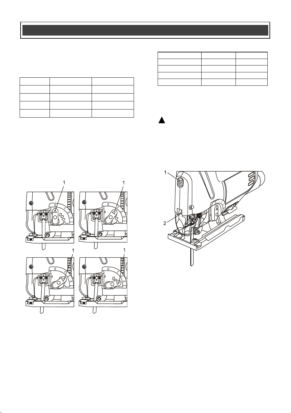
SETTING THE ORBITAL CUTTING ANGLE
The variable orbital cutting action allows you
to select one of four different blade angles.
To set the orbital cutting angle, rotate the
orbital cutting lever forward or backward to
the desired setting number (1) (Fig. 7).
NOTE: The orbital setting button will "click" at
each of the four positions. Slide the orbital
button slightly forward or backward until it
locks into place.
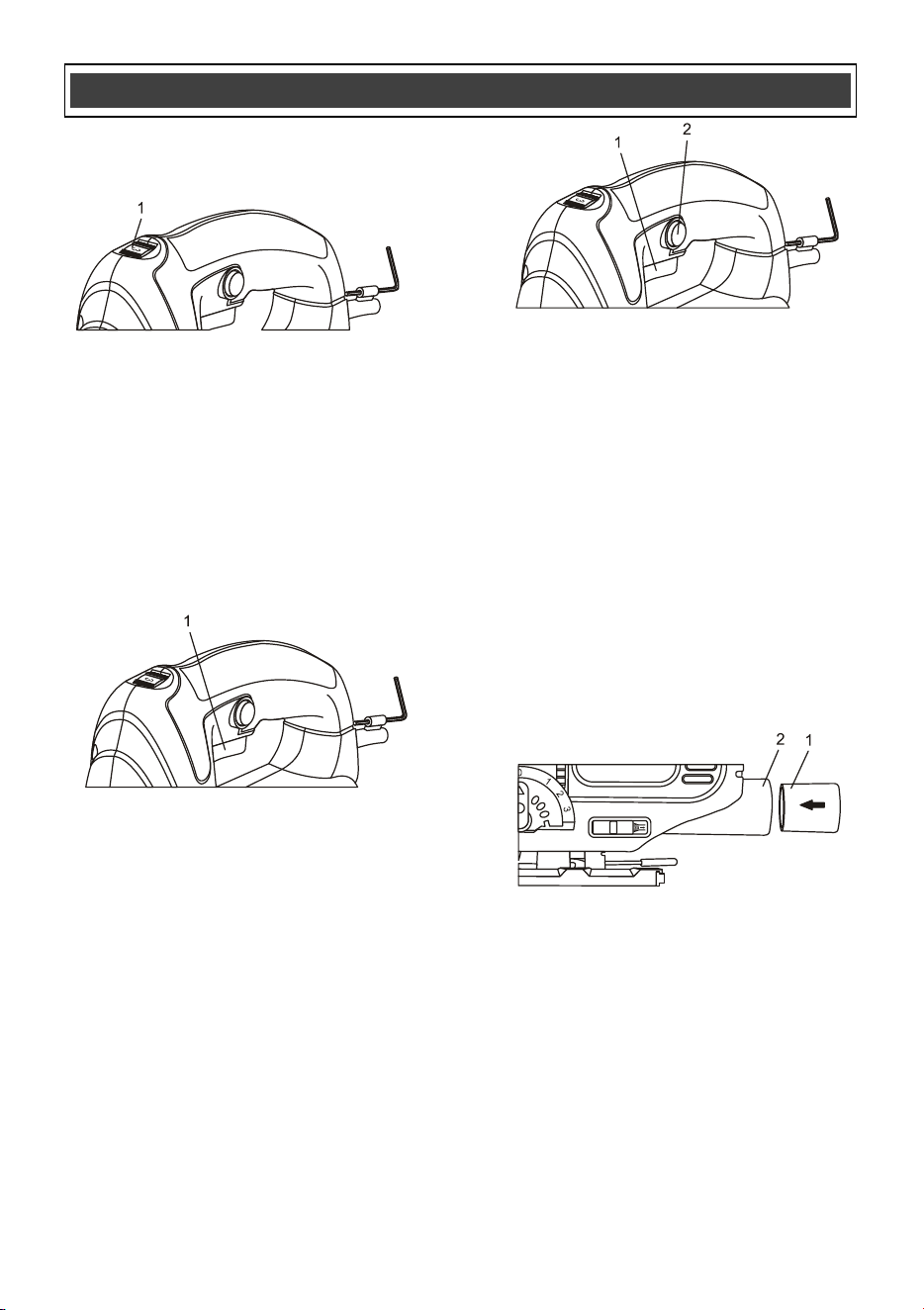
LASER / LED WORKLIGHT SWITCH
The laser / LED worklight switch (1) is located
in the front of the saw housing (Fig. 8). This 4
position switch turns the laser and LED
worklight (2) ON and OFF. The following
chart indicates the status of each component.
Press switch
LED light
Laser
Once
ON
OFF
Twice
OFF
ON
Three times
ON
ON
Four times
OFF
OFF
To turn either the laser or LED worklight ON
or OFF, press the switch the number of times
indicated in the above chart.
DANGER: Never point the laser at
anyone or look directly into the laser beam.
The laser beam can cause blindness.
The laser beam will throw a marker beam on
the workpiece to help you guide the jigsaw
through the desired cutting pattern
VARIABLE SPEED CONTROL WHEEL
Set the jigsaw speed by rotating the variable
speed control wheel (1) to the appropriate
speed (Fig. 9). Rotating the variable speed
control wheel toward the rear of the jigsaw
will result in slower speeds. Position the
speed control dial at "1" for the slowest
speed, "3" for medium speed and at "6" for
the highest speed.
ASSEMBLY AND OPERATION
Position
Angle
Material
0
Neutral
Metal
1
Small
Hard wood
2
Large
Soft wood
3
Full
Styrofoam
Fig. 7
Fig. 8
!
14
VARIABLE SPEED CONTROL WHEEL – cont’d
TRIGGER SWITCH
The trigger switch turns the jigsaw ON and
OFF.
1. To turn the jigsaw ON, squeeze the
trigger switch (1) (Fig. 10).
2. To turn the jigsaw OFF, release the
trigger switch.
LOCK-ON BUTTON
Your jigsaw is equipped with a lock-on
feature, which is convenient when continuous
cutting for extended periods of time is
required (Fig. 11). To lock the switch ON,
depress the trigger switch (1), push in and
hold the lock-on button (2) located at the left
side of the handle, then release the trigger.
Release the lock-on button and your jigsaw
will continue running. To turn the jigsaw OFF,
depress and release the trigger switch to
release lock.
INSTALLING THE VACUUM ADAPTOR
To reduce the amount of loose sawdust
produced while cutting, a workshop vacuum
can be attached to the jigsaw by using the
vacuum adapter supplied with the jigsaw.
To install the vacuum adapter (1), insert the
adapter into the vacuum port (2) in the rear of
the jigsaw housing (Fig. 12).
NOTES:
a) The vacuum adapter is slightly tapered. If
the adapter is too large to be inserted into the
vacuum port, insert the opposite end of the
adaptor into the vacuum port.
a) Twist the adapter slightly as it is pressed
into the vacuum port to ensure it is fully
inserted.
VACUUM PORT SWITCH
During normal use without the vacuum
adaptor installed, the vacuum port switch (1)
must be slid toward the front of the tool
(Fig. 13). This will allow the internal motor fan
to continuously blow the sawdust away from
the cutting mark. When the vacuum adaptor
is installed, the vacuum port switch must be
slid toward the rear of the tool. This positions
the internal baffle to divert the sawdust
through the vacuum port so it can be
evacuated by the workshop vacuum.
Fig. 9
Fig. 9
ASSEMBLY AND OPERATION
Fig. 10
Fig. 11
Fig. 12
Fig. 13

15
VACUUM PORT SWITCH – cont’d
MATERIALS YOU CAN CUT
This jigsaw is a versatile tool that allows you
to cut many different types of materials. Some
of these materials include:
Wood products such as lumber,
hardwood, plywood, composite board,
and panelling
Drywall
Styrofoam
Fibre board and plastic
Metals such as pipe, steel rods, sheet
steel, aluminum, brass, and copper.
NOTE: There are many different types of
blades available. Generally, there are metal
cutting blades (fine teeth) and wood cutting
blades (coarse teeth). Use the correct blade
for your application. The packaging on the
blade will indicate the type of materials each
blade is designed to cut.
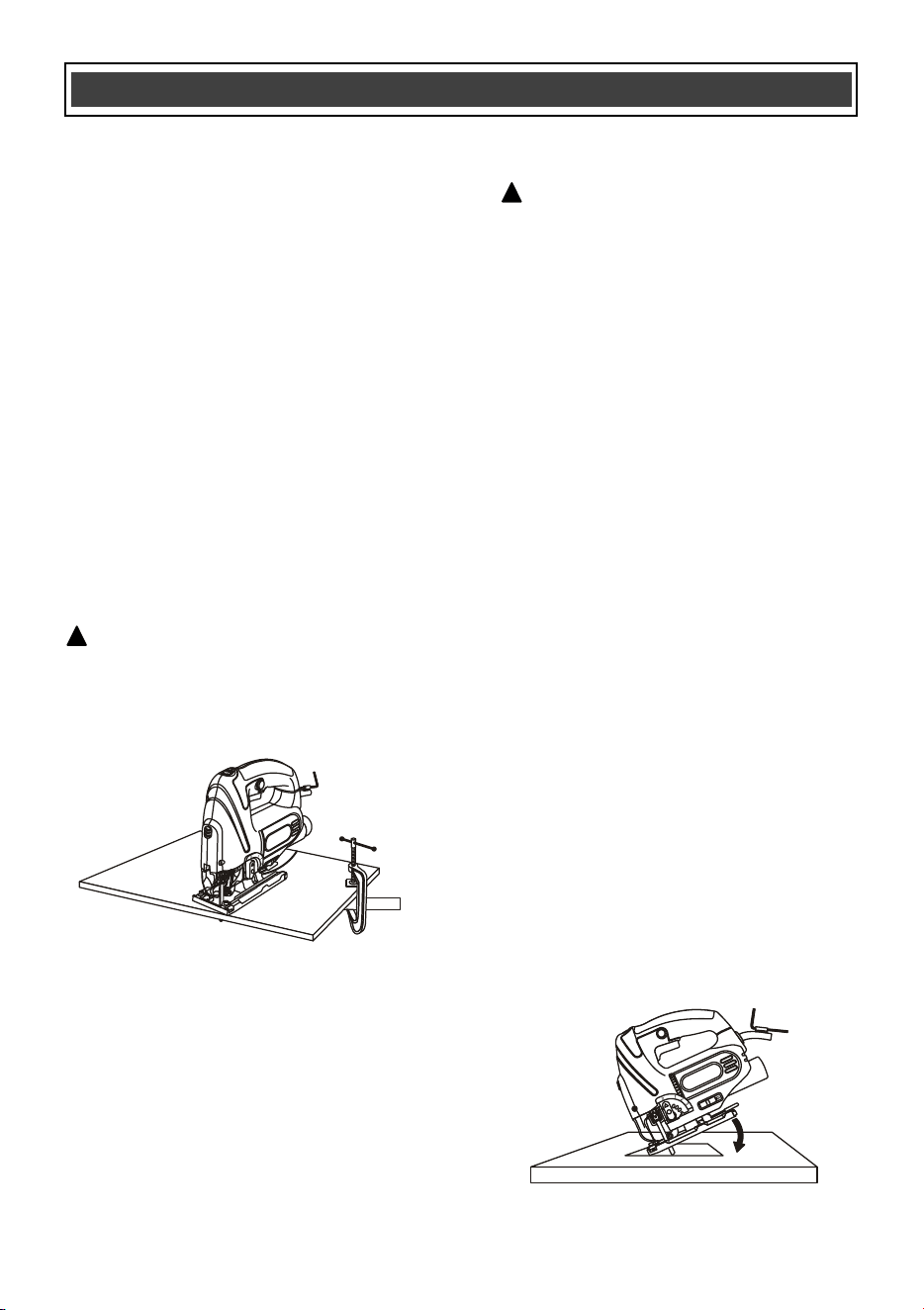
GENERAL CUTTING
1. Clearly mark the workpiece to locate the
position of the cut.
2. Hold smaller workpieces with a vise.
Clamp larger workpieces to a workbench
or table.
DANGER: Any workpiece that is not
adequately clamped in place may come
loose and cause serious injury. Never hold
the workpiece with your hand.
WARNING: Keep your hands and
fingers away from between the motor
housing and the blade holder. Do not
reach underneath the workpiece while the
jigsaw is running.
ASSEMBLY AND OPERATION
Fig. 13
!
WARNING
For safety reasons, the operator must
read the sections of this Owner’s
Manual entitled "GENERAL SAFETY
WARNINGS", "POWER TOOL
SAFETY", "SPECIFIC SAFETY
RULES", "EXTENSION CORD
SAFETY" and "SYMBOLS" before
using this jigsaw.
Verify the following every time the
jigsaw is used:
1. The blade is sharp and in good
condition.
2. The blade is firmly clamped into
the blade holder.
3. The workpiece is properly
secured.
4. Safety glasses and hearing
protection are being worn.
Failure to observe these safety rules
will significantly increase the risk of
injury.
!
!
16
GENERAL CUTTING – cont’d
3. Rest the front of the jigsaw base on the
workpiece and align cutting edge of the
blade with the cutting line on your
workpiece (Fig. 14). Make sure the
power cord is out of your way and not in
the path the blade will follow.
4. While firmly gripping the jigsaw, and with
the blade NOT in contact with the
surface to be cut, start the jigsaw by
squeezing the trigger switch.
5. Once the jigsaw has reached the desired
speed, gradually bring the moving blade
into contact with the workpiece at the
appropriate location.
NOTE: Apply enough downward pressure to
keep the jigsaw steady and only enough
forward pressure to keep the blade cutting
freely.
CAUTION: Do not force the jigsaw.
Use only enough force to keep the blade
cutting. Excessive pressure on the blade
will cause it to bend and twist, which may
result in breaking the blade.
BEVEL CUTTING
Bevel cutting angles may be adjusted from 0°
to 45° either left or right. To adjust the bevel
angle, refer to Fig. 4, 5 & 6.
Once the cutting angle has been verified,
proceed with the cutting activity as outlined in
"GENERAL CUTTING" above.
PLUNGE CUTTING
WARNING: To avoid loss of control,
broken blades or damage to the
workpiece, always use extreme caution
when making plunge cuts. It is not
recommended to plunge cut any material
other than wood. Wherever possible, drill
a pilot hole 3/8" (9.5 mm) or larger in the
area to be cut out and start cutting with
the blade in the pilot hole. This will avoid
the need to plunge cut.
NOTE: Use only blades with 7 teeth per
inch for plunge cutting.
1. To plunge cut an inside hole, clearly
mark the cutting line on the workpiece.
2. Set the bevel angle at 0°, and then lock
the base plate.
3. Tilt the jigsaw forward so it rests on the
front edge of the base plate and in a
position where the blade will NOT touch
the workpiece when the switch is turned
ON (Fig. 15).
NOTE: Make sure the saw blade is inside the
area to be cut.
4. Start the jigsaw and slowly lower the
blade onto the workpiece while making
sure the front of the saw base remains in
contact with the workpiece. Allow the
blade to slowly cut through the wood.
5. Continue lowering the blade into the
workpiece until the jigsaw base rests flat
on the workpiece. Continue sawing
toward the cutting line and complete the
cut as required.
ASSEMBLY AND OPERATION
!
Fig. 14
Fig. 15
!
Fig. 15

17
METAL CUTTING
Many types of metal can be cut with your
jigsaw. When cutting any kind of material, be
careful not to twist or bend the blades. Do not
force the blade. If the blade chatters or
vibrates excessively, use a finer toothed
blade. If the blade heats excessively, reduce
the speed of cutting. If the blade teeth
become clogged when cutting soft metals,
such as aluminum, use a coarser blade with
fewer teeth per inch. Use kerosene when
cutting soft metals and oil when cutting steel
to keep the blade cool and to extend the
blade life. Clamp all work firmly and saw as
close as possible to the clamping point to
eliminate any vibration of the work being cut.
When cutting conduit, pipe or angle iron,
clamp the workpiece in a vise if possible and
saw close to the vise. To cut thin sheet
materials, "sandwich" the material between
hardboard or plywood and clamp the layers to
eliminate material vibration and tearing. By
doing this, the material will be cut smoothly.
Lay out your pattern or cutting lines on top of
the "sandwich".
ASSEMBLY AND OPERATION

18
GENERAL
WARNING: When servicing this tool,
use only identical replacement parts. The
use of any other part may create a hazard
or cause product damage.
DO NOT use solvents when cleaning plastic
parts. Plastics are susceptible to damage
from various types of commercial solvents
and may be damaged by their use. Use a
clean cloth to remove dirt, dust, oil, grease
etc.
WARNING: Do not allow brake fluids,
gasoline, petroleum-based products,
penetrating oils, etc. to come into contact
with plastic parts. They contain chemicals
that can damage, weaken or destroy
plastic.
DO NOT abuse power tools. Abusive
practices can damage the tool and the
workpiece.
WARNING: DO NOT attempt to
modify tools or create accessories. Any
such alteration or modification is misuse
and could result in a hazardous condition
leading to possible serious injury. It will
also void the warranty.
It has been found that electric tools are
subjected to accelerated wear and possible
premature failure when they are used on
fiberglass boats and sports cars, wallboard,
spackling compounds or plaster. The chips
and grindings from these materials are highly
abrasive to electric tool parts such as
bearings, brushes, commutators, etc.
Consequently, it is not recommended that this
tool be used for extended work on any
fiberglass material, wallboard, spackling
compounds or plaster. During any use on
these materials it is extremely important that
the tool is cleaned frequently by blowing the
accumulated debris out with an air jet.
WARNING: Always wear safety
goggles or safety glasses with side
shields during all cutting operations. It is
critical that you wear safety goggles or
safety glasses with side shields and a
dust mask while blowing dust out of the
jigsaw with an air jet. Failure to take these
safety precautions could result in
permanent eye or lung damage.
LUBRICATION
All of the bearings in this tool are lubricated
with a sufficient amount of high-grade
lubricant for the life of the unit under normal
conditions. Therefore, no further lubrication is
required.
MAINTENANCE
!
!
!
!
!
19
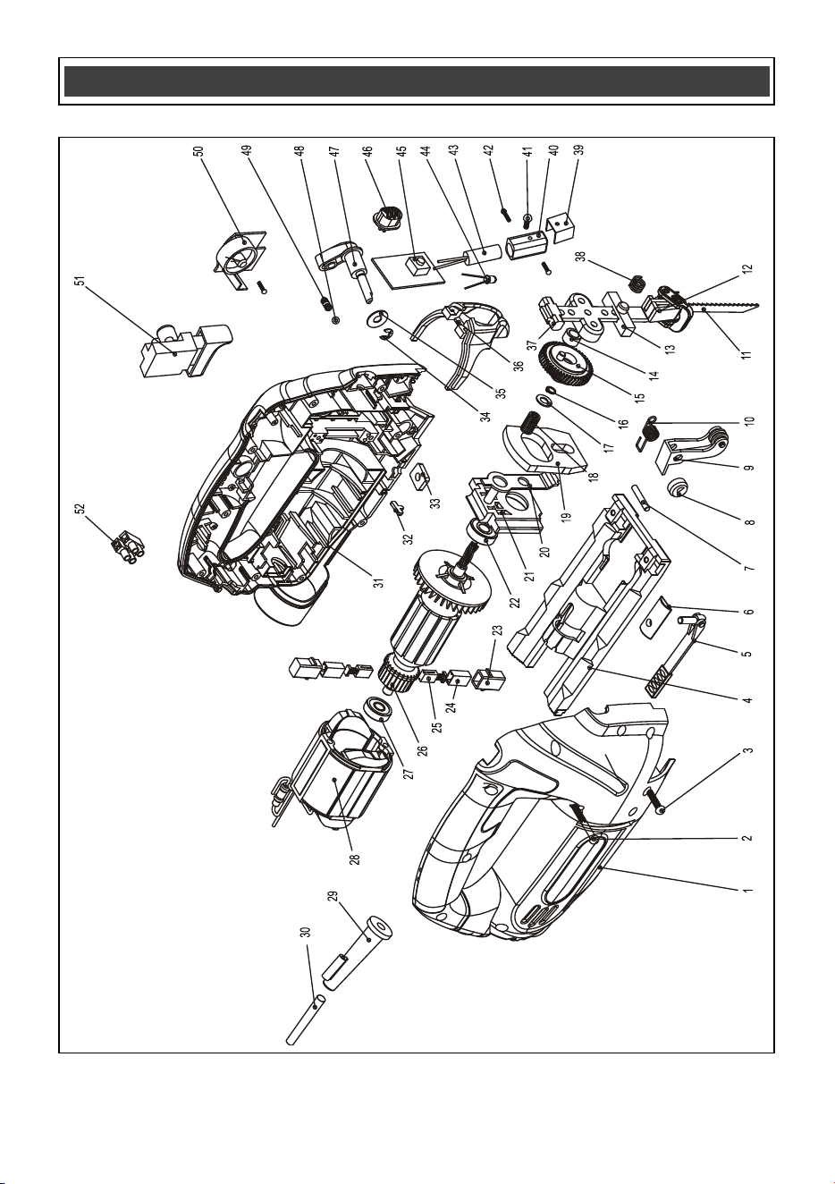
EXPLODED VIEW

20
WARNING: When servicing, use only original equipment replacement parts. The use of any other
parts may create a safety hazard or cause damage to the jigsaw.
Any attempt to repair or replace electrical parts on this jigsaw may create a safety hazard unless
repairs are performed by a qualified technician. For more information, call the Toll-free Helpline, at 1-
866-349-8665.
Always order by PART NUMBER, not by key number.
Key #
Part #
Part Name
Quantity
1
3011100061
Right enclosure
1
2
4030010124
Tapping screw 3.9 X 39
2
3
4030010106
Tapping screw 3.9 X 19
10
4
1150020001
Foot plate
1
5
2040140041
Quick release wrench
1
6
2030030008
Fixing plate
1
7
4110030001
Pin
1
8
2010130017
Eccentric wheel
1
9
1170020003
Roller support
1
10
2050050001
Torsion-spring
1
11
6060010006
Blade
1
12
1150010003
Quick release plunger assembly
1
13
2010150002
Front bearing
1
14
2010210008
Roller
1
15
1170060014
Big Gear
1
16
4100020004
Fixing ring
1
17
2030020011
Washer
1
18
4010020012
Needle roller bearing
1
19
2010130012
Balance Block
1
20
2030030039
Pendulum bar
1
21
1170050003
Bearing holder
1
22
4010010039
Bearing 629
1
23
3150060002
Brush holder
2
24
2030070004
Brush holder support
2
25
1230010001
Carbon brush
2
!
PARTS LIST

21
Key #
Part #
Part Name
Quantity
26
1010100057
Rotor
1
27
4010010034
Bearing 607
1
28
1020100055
Stator
1
29
3140010077
Cord sleeve
1
30
1190010040
Cord & plug
1
31
3011100061
Left enclosure
1
32
2030030219
Connecting plate
1
33
4060020013
Nut
1
34
4100050002
Fixing ring
1
35
2030020012
Washer
1
36
2050080157
Finger guard
1
37
2010150003
Back bearing
1
38
2050060001
Spring
1
39
2030130036
Laser holder
1
40
3160060008
Cover
1
41
3110020041
Screw M3 X 5
1
42
4030010034
Tapping screw 2.9 X 16
2
43
1220030007
Laser head
1
44
1220030007
LED
1
45
1130030032
PCB for laser
1
46
3120010051
Laser head button
1
47
1180050048
Pendulum switch knob
1
48
4080060001
Metal ball
1
49
2050060080
Spring
1
50
1130010173
PCB
1
51
1061090050
Switch
1
52
1250010002
Terminal block
2
PARTS LIST

22
Rev 1.9 27/10/2016
PERFORMAX
®
6 AMP JIGSAW WARRANTY
30-DAY MONEY BACK GUARANTEE:
This PERFORMAX
®
brand power tool carries our 30-Day Money Back
Guarantee. If you are not completely satisfied with your PERFORMAX
®
brand
power tool for any reason within thirty (30) days from the date of purchase, return
the tool with your original receipt to any MENARDS
®
retail store, and we will
provide you a refund – no questions asked.
2-YEAR LIMITED WARRANTY:
This PERFORMAX
®
brand power tool carries a 2-Year Limited Warranty to the
original purchaser. If, during normal use, this PERFORMAX
®
power tool breaks
or fails due to a defect in material or workmanship within two (2) years from the
date of original purchase, simply bring this tool with the original sales receipt
back to your nearest MENARDS® retail store. At its discretion, PERFORMAX
®
agrees to have the tool or any defective part(s) repaired or replaced with the
same or similar PERFORMAX
®
product or part free of charge, within the stated
warranty period, when returned by the original purchaser with original sales
receipt. Not withstanding the foregoing, this limited warranty does not cover any
damage that has resulted from abuse or misuse of the Merchandise. This
warranty: (1) excludes expendable parts including but not limited to blades,
brushes, belts, bits, light bulbs, and/or batteries; (2) shall be void if this tool is
used for commercial and/or rental purposes; and (3) does not cover any losses,
injuries to persons/property or costs. This warranty does give you specific legal
rights and you may have other rights, which vary from state to state. Be careful,
tools are dangerous if improperly used or maintained. Seller’s employees are
not qualified to advise you on the use of this Merchandise. Any oral
representation(s) made will not be binding on seller or its employees. The rights
under this limited warranty are to the original purchaser of the Merchandise and
may not be transferred to any subsequent owner. This limited warranty is in lieu
of all warranties, expressed or implied including warranties or merchantability
and fitness for a particular purpose. Seller shall not be liable for any special,
incidental, or consequential damages. The sole exclusive remedy against the
seller will be for the replacement of any defects as provided herein, as long as
the seller is willing or able to replace this product or is willing to refund the
purchase price as provided above. For insurance purposes, seller is not allowed
to demonstrate any of these power tools for you.
For questions / comments, technical assistance or repair parts –
Please Call Toll Free at: 1-866-349-8665 (M-F 8am – 6pm)
SAVE YOUR RECEIPTS. THIS WARRANTY IS VOID WITHOUT THEM.
Distributed by: Menard, Inc., Eau Claire, WI 54703