
SCREW TORQUE SPECIFICATIONS
FIG. PART NO. WHERE USED
SEAT TORQUE
kgf-cm lb-in
21
06-82-0243
Screw M2 x 0.89 PH Torx T6 3+/-0.5 2.6+/-4
34
06-82-6351 Screw M3 x 1.06 mm
8.5+/-1 7.4+/-1
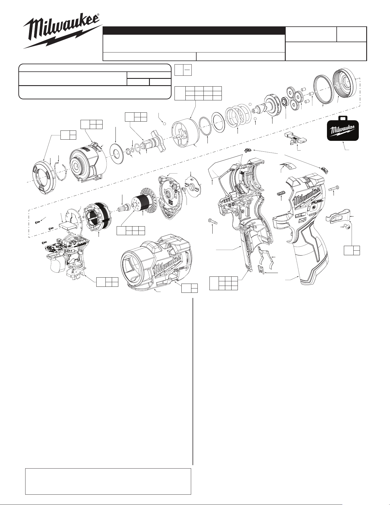
EXAMPLE:
Component Parts (Small #) Are Included When
Ordering The Assembly (Large #).
0
00
FIG. 51, 52 NOTES:
Adhesive labels and nameplates must be put on a clean and dry
surface. Use a clean, lint-free cloth to wipe the area with isopropyl
alcohol. Let the surface dry before you apply the label or name plate.
FIG. PART NO. DESCRIPTION OF PART NO. REQ.
1 --------------- Shadowless Worklight Wire Harness (1)
2 --------------- Shadowless Retaining Ring (1)
3 --------------- Gearcase (1)
4 45-88-2554 Gearcase Washer (1)
5 --------------- Friction Ring (1)
6 --------------- Rubber O-Ring 7.4 mm O.D. (1)
7 --------------- Rubber O-Ring 13.5 mm O.D. (1)
8 --------------- 3/8" Anvil (1)
9 02-02-0098 Ball Bearing Steel 7.0 mm Dia. (2)
10 --------------- Hammer (1)
11 --------------- Ball Bearing Ring GCr15 (1)
12 --------------- Hammer Washer (1)
13 --------------- Hammer Spring (1)
14 02-02-1100 Ball Bearing GCr15 4.0 mm Dia (2)
15 --------------- Camshaft (1)
16 --------------- Ball Bearing MR148-2RS 14 mm O.D. (1)
17 --------------- Planet Gear (3)
18 --------------- Planet Pin (3)
19 --------------- Rubber Gearbox Sleeve (1)
20 --------------- Ring Gear (1)
21 06-82-0243 PT Screw M2 x 0.89 Torx T6 (3)
22 --------------- Foam Pad for PCB Assembly (1)
23 --------------- PCB Assembly (1)
24 --------------- Motor Field 12V-DC Bl40 (1)
25 --------------- Motor Pinion (1)
26 --------------- Injection Rotor (1)
FIG. PART NO. DESCRIPTION OF PART NO. REQ.
27 --------------- Back Cap w/ Bearing (1)
28 --------------- Retaining Ring 6.5 mm O.D. (1)
29 44-66-0120 Logo Plate (1)
30 45-24-0036 Forward and Reverse Shuttle (1)
31 --------------- Right Housing Half - Cover (1)
32 --------------- Left Housing Half - Support (1)
33 45-24-0037 Mode Select Lens (2)
34 06-82-6351 Screw M3 x 1.06 mm (9)
35 42-70-0058 Housing Connector (1)
36 42-70-0480 Spring Clip (1)
37 --------------- Belt Clip (1)
38 --------------- Screw M6-32 (1)
39 44-06-0052 Fuel Gauge Lens (1)
40 42-38-0058 Rubber Boot (1)
50 12-20-2017 Service Nameplate (1)
52 10-22-2966 Gauge Label (1)
100 14-20-0390 Shadowless Assembly (1)
101 14-29-0195 Gearcase Assembly (1)
102 42-06-0050 Anvil Assembly (1)
103 14-20-0391 Mechanism Assembly (1)
104 14-20-0392 Electronics Assembly (1)
105 14-20-0393 Rotor Assembly (1)
106 31-44-0200 Handle Assembly (1)
111 42-70-0044 Belt Clip Assembly (1)
112 42-55-3400 Contractor Bag (1)
120 42-38-0059 Rubber Boot Assembly (1)
102
5 6
7 8
105
25 26 27
28 29
111
37
38
120
40
10 11 12 13
14 15 16 17
18 19 20
103
100
1
2
101
1 2
3
104
21 22
23 24
106
21 32 33
34 35 36
39 50 52
40
28
25
52
112
3
26
24
34
(x4)
29
22
23
38
37
33
(x2)
27
30
21
(x3)
6
11
10
8
7
5
12
13
14
(x2)
15
16
17
(x3)
18
(x3)
19
20
4
2
1
9
34
(x5)
31
50
39
32
36
35
MILWAUKEE TOOL
l
www.milwaukeetool.com
13135 W. LISBON RD., BROOKFIELD, WI 53005
Drwg. 1
SERVICE PARTS LIST
BULLETIN NO.
PN0007936
SPECIFY CATALOG NO. AND SERIAL NO. WHEN ORDERING PARTS
REVISED BULLETIN
DATE
July 2025
M12 FUEL™ 3/8" Subcompact Impact Wrench
w/ Friction Ring
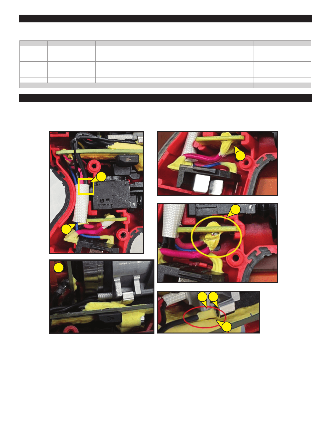
WIRING INSTRUCTION
See Page 2
CATALOG NO. 3049-20 SERIAL NO. R46A
A
B
C
D
E
G
FF
The bottom position of the sliding tube must be level with the HIT board (A). The trigger wire must be below the sliding tube (B).
Make sure the glue fully covers the wires (C) and is not damaged (D). The wires must be fully connected (E) without gaps (F) or separation (G).
All components must be tight and aligned correctly to prevent interference when the housing cover is installed.
WIRING AND ELECTRONICS ASSEMBLY INSTRUCTIONS
FIG. PART DESCRIPTION INSTRUCTIONS AMOUNT
8 Anvil Put grease on the body of the anvil 0.4 g
10 Hammer Put grease on the hammer 0.9 g
12 Hammer Washer Put grease on the hammer washer 0.1 g
15 Camshaft
Put grease on the camshaft groove 0.6 g
Put grease on the camshaft hole 1.2 g
18 Planet Pin Put grease on the planet pin 0.1 g
20 Ring Gear Put grease on the thread, bottom face, and inner diameter of the ring gear 0.8 g
TOTAL AMOUNT OF GREASE: 4.5 g
Use Type 'J' Grease, No. 49-08-4220.
When servicing, remove 90-95% of the existing grease before applying the Type ‘J’ grease. The original grease could be similar in color but it is NOT
compatible with Type ‘J’ grease. The total amount of grease should not be more than 4.5 g.
LUBRICATION INSTRUCTIONS