heating.danfoss.com/new-solutions/ectemp-smart
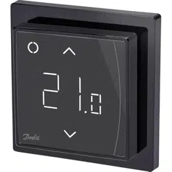
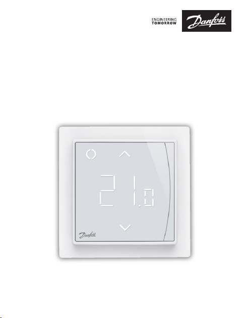
Danfoss ECtemp™ Smart
Intelligent Electronic Timer Thermostat
with Wi-Fi connectivity and App control
Installation Guide

Danfoss ECtemp™ Smart
Installation Guide2
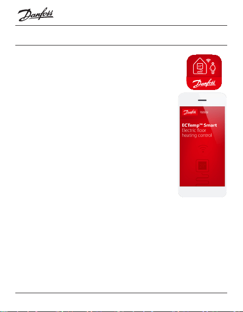
1 Introduction
ECtemp™ Smart is an electronic programmable timer
thermostat used for controlling electrical oor heating
elements. The thermostat is designed for xed installation
only and can be used for both direct heating of the entire
room and for comfort heating of the oor. Among others,
the thermostat has the following features:
1 Introduction . . . . . . . . . . . . . . . . . . . 2
2 Technical Specications . . . . . . . . . . . . 4
3 Safety Instructions . . . . . . . . . . . . . . . 6
4 Mounting Instructions . . . . . . . . . . . . . 8
5 Display Symbols. . . . . . . . . . . . . . . . 12
6 Conguring. . . . . . . . . . . . . . . . . . . 18
7 Settings . . . . . . . . . . . . . . . . . . . . . 19
8 Warranty. . . . . . . . . . . . . . . . . . . . . 22
9 Radio Equipment Directive . . . . . . . . 25
10 Disposal Instruction . . . . . . . . . . . . . 26
Table of Contents

Danfoss ECtemp™ Smart
3Installation Guide
• A touchscreen display with light.
• An easy-to-follow menu-driven programming and
operation.
• An installation wizard with room/oor type-specic
setup (requires an app).
• Support for multiple frame systems.
• Compatible with several 3rd party NTC sensors.
• Thermostat settings can be specied before instal-
lation and imported to the thermostat using a
web-generated code, or copied from a thermostat in
a similar installation.
• Smart access to thermostat settings after installa-
tion by using a web code interface, for easy setup or
remote troubleshooting.
Regarding Connectivity:
• 10 smart devices (like Smartphone or Tablet) can be
connected to 1 thermostat.
• 2 smart devices can be in contact with the thermo-
stat at the same time.
ECtemp™ SMART REQUIRES WORKING WI-FI
TO FUNCTION

Danfoss ECtemp™ Smart
Installation Guide4
More information on this product can also be found at:
http://heating.danfoss.com/new-solutions/ectemp-smart
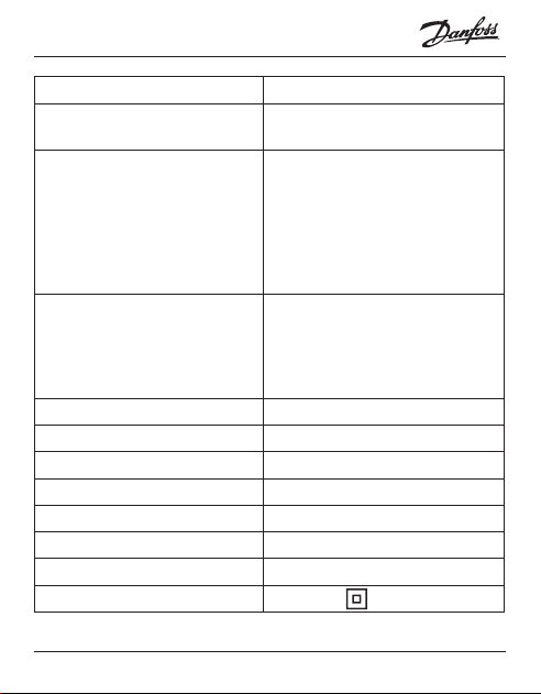
2 Technical Specications
Operation voltage 220-240 V~, 50/60 Hz
Standby power consumption Max. 0,40 W
Relay:
Resistive load
Inductive load
Max. 16 A / 3680 W @ 230 V
Max. 1 A cos φ= 0,3
Transmission Frequency 2,4 - 2,483.5 GHz
Transmission Power < 20 dBm
Sensing units NTC 6,8 kOhm at 25°C
NTC 10 kOhm at 25°C
NTC 12 kOhm at 25°C
NTC 15 kOhm at 25°C (Default)
NTC 33 kOhm at 25°C
NTC 47 kOhm at 25°C
Sensing values:
(Default NTC 15 K)
0°C
20°C
50°C
42 kOhm
18 kOhm
6 kOhm
Control PWM (Pulse Wide Modulation)
Danfoss ECtemp™ Smart
5Installation Guide
Ambient temperature 0 ° to +30 °C
Frost protection
temperature
5 °C to +9 °C (default 5 °C)
Temperature range Room temperature: 5-35 °C.
Floor temperature: 5-45 °C.
Max. oor: 20-35 °C (if unrecov-
erable seal is broken then up to
45 °C). Min. oor: 10-35 °C, only
with combination of room and
oor sensor.
Sensor failure monitoring The thermostat has a built-in
monitoring circuit, which will
switch o the heating if the
sensor is disconnected or short-
circuited
Cable specication max. 1x4 mm
2
Ball pressure test temperature 75 °C
Pollution degree 2 (domestic use)
Controller type 1C
Software class A
Storage temperature -20 °C to +65 °C
IP class 21
Protection class Class II -
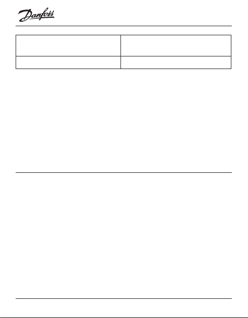
Danfoss ECtemp™ Smart
Installation Guide6
Dimensions 85 x 85 x 20-24 mm
(in-wall depth: 22 mm)
Weight 127 g
Electrical safety and Electro-Magnetic Compatibility for
this product is covered by the compliance with the EN/IEC
Standard “Automatic electrical controls for household and
similar use”:
• EN/IEC 60730-1 (general)
• EN/IEC 60730-2-9 (thermostat)
3 Safety Instructions
Make sure the mains supply to the thermostat is turned
o before installation.
Important: When the thermostat is used to control a
oor heating element in connection with a wooden oor
or similar material, always use a oor sensor and never set
the maximum oor temperature to more than 35 °C.

Danfoss ECtemp™ Smart
7Installation Guide
Please also note the following:
• The installation of the thermostat must be done by an
authorized and qualied installer according to local
regulations.
• The thermostat must be connected to a power supply
via an all-pole disconnection switch.
• Always connect the thermostat to continuous power
supply.
• Do not expose the thermostat to moisture, water,
dust, and excessive heat.
• This thermostat can be used by children aged from 8
years and above and persons with reduced physical,
sensory or mental capabilities or lack of experience
and knowledge, if they have been given supervision
or instruction concerning use of the appliance in a
safe way and understand the hazards involved, by a
person responsible for their safety.
• Children should be supervised to ensure that they do
not play with the thermostat.
• Cleaning and user maintenance shall not be made by
children without supervision.
Danfoss ECtemp™ Smart
Installation Guide8
4 Mounting Instructions
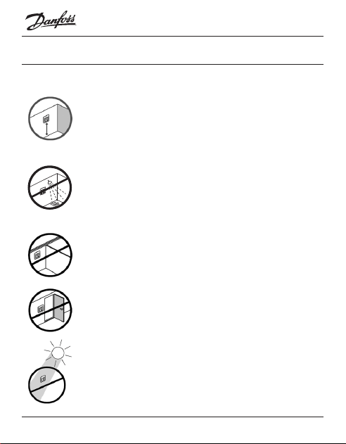
Please observe the following placement guidelines:
Place the thermostat at a suitable height on the wall
(typically 80-170 cm.).
The thermostat should not be placed in wet rooms.
Thermostat must be placed outside zone 2. Place it
in an adjacent room and use oor sensor only.
Always place the thermostat according to local
regulation on IP classes.
Do not place the thermostat on the inner side of a
poorly insulated exterior wall.
Always install the thermostat at least 50 cm from
windows and doors, due to draft, when using regu-
lation in: oor and room mode or room alone mode.
Do not place the thermostat in a way that it will be
exposed to direct sunlight.
Danfoss ECtemp™ Smart
9Installation Guide
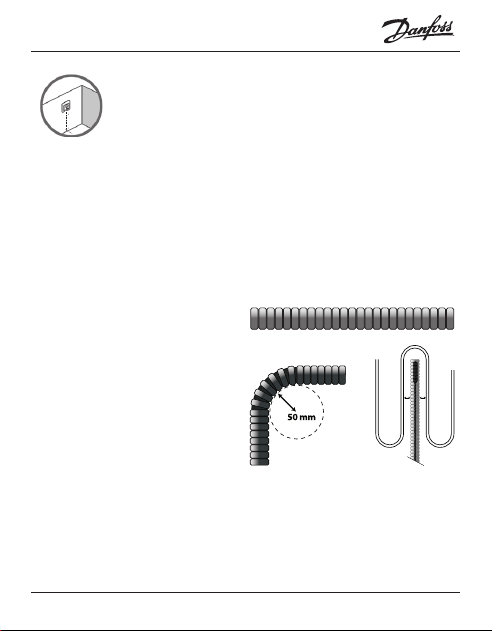
Note: A oor sensor is recommended in all oor
heating applications and mandatory to thin mats
under wooden oors to reduce the risk of
overheating the oor.
• Place the oor sensor in a protecting plastic conduit
in the oor construction in an appropriate place,
where the oor is not exposed to sunlight or draft
from door openings.
• Equally distant and >2 cm from the heating cables
on both sides.
• The conduit should
be ush with the oor
surface, countersink
the conduit if neces-
sary and possible.
• Route the conduit to
the connection box.
• The bending radius of the conduit must be min 50
mm.
1 2
≥
Danfoss ECtemp™ Smart
Installation Guide10
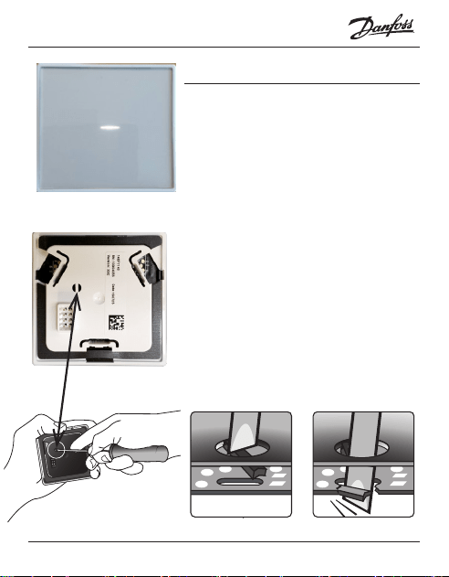
Follow the steps below to mount the thermostat:
1. Unpack thermostat
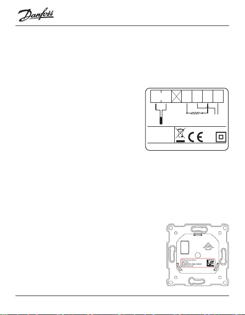
2. Connect the thermostat according to the connection
diagram.
The screen of the heating
cable must be connected to
the earth conductor of the
power supply cable by using
a separate connector.
Note: Always install the oor sensor in a conduit in
the oor.
3. Fasten the thermostat rmly to a ush mounted wall
box or an exterior wall box by driving the screws
through the holes in each side of the thermostat.
4. Add the frame before assembling
of top part to the snap locks/bot-
tom part.
5. Click the front part module in
place. Pay attention, in relation to
IP21
T30
Mains
220-240V~
50-60 Hz
Maximum
Load 16 (1) A
Sensor
NTC
Danfoss A/S
Nordborgvej 81
6430 Nordborg
Denmark
NLL
L
O
A
D
N
L
O
A
D
Standby maximum 0.4 Watt
Danfoss ECtemp™ Smart
11Installation Guide
the female header, in not to bending the connectors.
Press carefully until the frame is xed against the
rubber gasket.
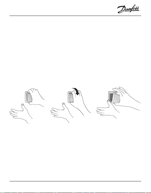
When mounting and reassembling the thermostat.
Important: Do NOT press in the center of the display screen.
Press your ngers under the side of the front part and pull
toward you until it releases from the snap lock:
To ensure that the batteries are fully charged, the ther-
mostat shall be connected to main supply for minimum
15 hours. The current time and day is kept for 24 hours if
mains supply is o.
All other settings are stored permanently.
Danfoss ECtemp™ Smart
Installation Guide12
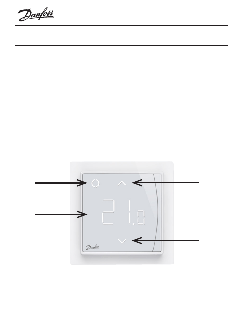
5 Display Symbols
Top part main functionalities are to support user interface
through display and hold all the controller logic.
Display main functionalities are to show the current status
of the Thermostat and recognize the user actions from the
buttons. Display consists of dierent buttons, numbers
and symbols.
1
4
2
3
Danfoss ECtemp™ Smart
13Installation Guide
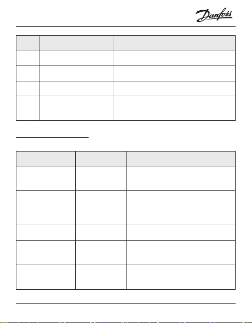
Nr. Type Description
1 Button/Symbol Control button
2 Button/Symbol Arrow Up button
3 Button/Symbol Arrow Down button
4 Symbol 3 digit 7 segment numbers with
comma separator
Symbol indications
Indication Mode/State Description
Blue - blinking Access Point
Mode
Thermostat ready for set-up
Blue Access Point
Mode
Smart phone connected
directly to thermostat for
set-up
Red - blinking Fault state Displays Error code
Red - slow
pulsing
Active Mode Indicating heating the oor
(Relay on)
Green -
constant
Active Mode Thermostat active and con-
nected to WiFi(Relay o)
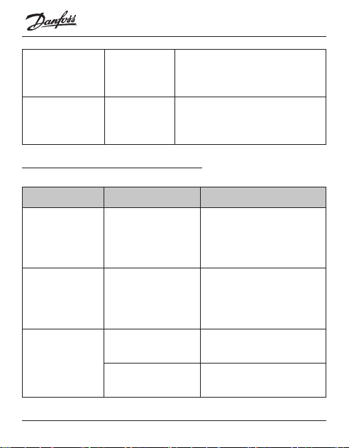
Danfoss ECtemp™ Smart
Installation Guide14
Green –
blinking
Active Mode
& Access
Point Mode
Thermostat waiting for conr-
mation of action
Arrows –
blinking rapidly
when touched
Active Mode Safety lock is on
Interaction directly on thermostat
Function Button Description
Turn thermo-
stat on
1. Touch any
button
2. Touch control
button (1)
Thermostat switch on
and display temperature
Turn thermo-
stat o
1. Touch any
button
2. Touch and hold
control button (1)
Thermostat display will
turn on
Thermostat count down
and switch o
Adjust set-
point
Up (2) Increases active mode/
temporary set point
Down (3) Decreases active mode/
temporary set point
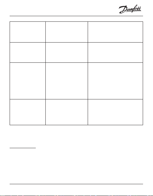
Danfoss ECtemp™ Smart
15Installation Guide
Frost protec-
tion
Touch and hold
Control (1) for
1 sec.
Deactivate frost protec-
tion
Safety lock Touch and hold
Up (2) + Down (3)
for 3 sec.
Activate/Deactivate
safety lock
Factory restore Touch and hold
Control (1) + Up
(2) for 5 sec.
After that touch
Control (1) again
to conrm
Activates factory restore
state
Away mode Touch and hold
Control (1) for 1
sec. to deactivate
Away mode
Activate/Deactivate
Away/Vacation mode
Error codes
When the error occurs and is resolved the thermostat, in
some cases, will require a restart to start heating again.
Danfoss ECtemp™ Smart
Installation Guide16
Error
type
Nr. Description Solu-
tion
Need restart
Floor
Sensor
discon-
nected
E1 Connection
to sensor is
lost
Contact
service
The thermostat
requires a restart
to operate again.
Floor
Sensor
short-
circuited
E2 Sensor
short-
circuited
Contact
service
The thermostat
requires a restart
to operate again.
Ther-
mostat
over-
heated
E3 Thermostat
is over-
heated,
heating is
turned o
Wait
until
ther-
mostat
cools
down
The thermostat
requires no
restart, but will
start heat-
ing when the
temperature is
lowered
Unrecov-
erable
error
E4 Room
temperature
sensor value
too high or
too low
Contact
service
The thermostat
requires a restart
to operate again.
Danfoss ECtemp™ Smart
17Installation Guide
Communication Error Codes
Communication
error
Nr. Description
Wrong SSID or
password
C1 STA trying to connect to the AP
No IP address C2 STA - connection acquired, no IP
yet, waiting for conguration data.
No internet con-
nection
C3 STA connected and has an IP from
DHCP server.
Danfoss ECtemp™ Smart
Installation Guide18
6 Conguring
Download App
Download the Danfoss Smart™ App from App
Store or Google Play or http://heating.danfoss.com/
new-solutions/ectemp-smart.
Find WiFi name and password for the WiFi
network, that you would like to connect your
thermostat to. If in doubt contact network
administrator or internet service provider.
Identify your oor sensor type ( in kOhm).
Identify your installed heating output (in W),
from label on the heating element.
Power on the thermostat, and it will show “-“
in the display. Then it is ready to be congured using your
iPhone and Android device.
Open the Danfoss Smart™ App and follow the instructions
and set-up ow in the App.
Danfoss ECtemp™ Smart indication
The Danfoss ECtemp™ Smart shows “–” indicating that power
is ON, but still need to be congured.
Danfoss ECtemp™ Smart
19Installation Guide
7 Settings
IMPORTANT DURING SET-UP
Select whether only a oor sensor
or a combination of room and oor
sensor should be used.
A “room only” option is also avail-
able, but requires that you have to
break the small plastic seal on the
back of the display module, e.g. us-
ing a screwdriver; it will be possible
to set the maximum oor tempera-
ture up to 45°. Furthermore, it will be
possible to use only a room sensor.
However, this option is not recom-
mendable due to an increased risk
of overheating the oor.
Danfoss ECtemp™ Smart
Installation Guide20
IMPORTANT: When the thermostat is used to control a
oor heating element in connection with a wooden oor
or similar material, always use a oor sensor and never set
the maximum oor temperature to more than 35°C.
Note: Please contact the oor supplier before changing
the maximum oor temperature and be aware of the
following:
• The oor temperature is measured there, where the
sensor is placed.
• The temperature of the bottom of a wooden oor
can be up to 10˚C higher than the top.
• Floor manufactures often specify the max. tempera-
ture on the top surface of the oor.
Danfoss ECtemp™ Smart
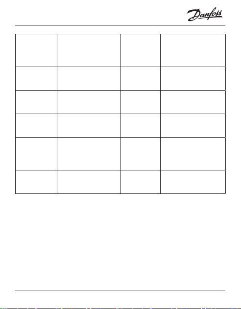
21Installation Guide
Thermal
resistance
[m
2
K/ W]
Examples of
ooring
Details
kg/m
3
Approximate
setting for 25°C
oor temperature
0,05 8 mm HDF based
laminate
> 800 28°C
0,10 14 mm beech
parquet
650 – 800 31°C
0,13 22 mm solid oak
plank
> 800 32°C
< 0,17 Max. carpet thick-
ness suitable for
oor heating
acc. to EN
1307
34°C
0,18 22 mm solid r
planks
450 – 650 35°C

Danfoss ECtemp™ Smart
Installation Guide22
8 Warranty
A 5-year product warranty is valid for:
• thermostats: ECtemp Smart.
Should you, against all expectations, experience a problem
with your Danfoss product, you will nd that Danfoss oers
Danfoss warranty valid from the date of purchase on the fol-
lowing conditions: During the warranty period Danfoss shall
oer a new comparable product or repair the product if the
product is found to be faulty by reason of defective design,
materials or workmanship. The repair or replacement.
The decision to either repair or replace will be solely at the
discretion of Danfoss. Danfoss shall not be liable for any
consequential or incidental damages including, but not
limited to, damages to property or extra utility expenses. No
extension of the warranty period following repairs under-
taken is granted.
The warranty shall be valid only if the WARRANTY CERTIFI-
CATE is completed correctly and in accordance with the
instructions, the fault is submitted to the installer or the seller
without undue delay and proof of purchase is provided.
Please note that the WARRANTY CERTIFICATE must be lled
in, stamped and signed by the authorized installer perform-
Danfoss ECtemp™ Smart
23Installation Guide
ing the installation (Installation date must be indicated). After
the installation is performed, store and keep the WARRANTY
CERTIFICATE and purchase documents (invoice, receipt or
similar) during the whole warranty period.
Danfoss warranty shall not cover any damage caused by
incorrect conditions of use, incorrect installation or if installa-
tion has been carried out by non-authorized electricians. All
work will be invoiced in full if Danfoss is required to inspect
or repair faults that have arisen as a result of any of the above.
The Danfoss warranty shall not extend to products which
have not been paid in full. Danfoss will, at all times, provide a
rapid and eective response to all com-
plaints and inquiries from our customers.
The warranty explicitly excludes all claims
exceeding the above conditions.
For full warranty text please use QR code
Danfoss ECtemp™ Smart
Installation Guide24
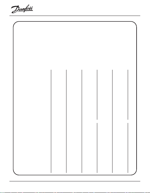
WARRANTY CERTIFICATE
The Danfoss warranty is granted to:
Address Stamp
Purchase date
Serial number of the
product
Product Art. No.
*Connected output [W]
Installation Date
& Signature
Connection Date
& Signature
*Not mandatory

Danfoss ECtemp™ Smart
25Installation Guide
9 Radio Equipment Directive
SIMPLIFIED EU DECLARATION OF CONFORMITY
Hereby, Danfoss A/S declares that the radio
equipment type ECtemp™ Smart is in compliance with
Directive 2014/53/EU
The full text of the EU declaration of conformity is
available at the following internet address:
https://assets.danfoss.com/approvals/latest/238288/
ID365935501519-0501.pdf

Danfoss ECtemp™ Smart
Installation Guide26
10 Disposal Instruction
This symbol on the product indicates that it may not be
disposed of as household waste.
It must be handed over to the applicable take-back
scheme for the recycling of electrical and electronic
equipment.
• Dispose of the product through channels provided for
this purpose.
• Comply with all local and currently applicable laws and
regulations.

Danfoss ECtemp™ Smart
27Installation Guide
Danfoss ECtemp™ Smart
Produced by Danfoss © 04/20248096305 & AN210086473616en-020204
Danfoss A/S
Nordborgvej 81
6430 Nordborg, Syddanmark
Denmark
8096305
8096305