1F80-3611F80-361
1F80-3611F80-361
1F80-361
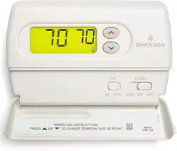
Programmable Electronic Digital Thermostat
INSTALLATION ANDINSTALLATION AND
INSTALLATION ANDINSTALLATION AND
INSTALLATION AND
OPERATION INSTRUCTIONSOPERATION INSTRUCTIONS
OPERATION INSTRUCTIONSOPERATION INSTRUCTIONS
OPERATION INSTRUCTIONS
FAILURE TO READ AND FOLLOW ALL INSTRUCTIONS CAREFULLYFAILURE TO READ AND FOLLOW ALL INSTRUCTIONS CAREFULLY
FAILURE TO READ AND FOLLOW ALL INSTRUCTIONS CAREFULLYFAILURE TO READ AND FOLLOW ALL INSTRUCTIONS CAREFULLY
FAILURE TO READ AND FOLLOW ALL INSTRUCTIONS CAREFULLY
BEFORE INSTALLING OR OPERATING THIS CONTROL COULD CAUSEBEFORE INSTALLING OR OPERATING THIS CONTROL COULD CAUSE
BEFORE INSTALLING OR OPERATING THIS CONTROL COULD CAUSEBEFORE INSTALLING OR OPERATING THIS CONTROL COULD CAUSE
BEFORE INSTALLING OR OPERATING THIS CONTROL COULD CAUSE
PERSONAL INJURY AND/OR PROPERTY DAMAGE.PERSONAL INJURY AND/OR PROPERTY DAMAGE.
PERSONAL INJURY AND/OR PROPERTY DAMAGE.PERSONAL INJURY AND/OR PROPERTY DAMAGE.
PERSONAL INJURY AND/OR PROPERTY DAMAGE.
DESCRIPTIONDESCRIPTION
DESCRIPTIONDESCRIPTION
DESCRIPTION
• Temperature override until next program period
• Manual program override (HOLD temperature)
• Temporary HOLD
• °F/°C convertibility
• Temperature range 45° to 90°F
• RC, RH, C, W, Y, G , O and B terminals
• Optional C terminal (Dual Power option)
• B and O terminals for single stage heat pumps (no auxiliary
heat) or damper operation
• Program storage in case of power loss
• 2 “AA” alkaline batteries included
OperOper
OperOper
Oper
aa
aa
a
tortor
tortor
tor
::
::
:
Sa Sa
Sa Sa
Sa
vv
vv
v
e these instre these instr
e these instre these instr
e these instr
uctions fuctions f
uctions fuctions f
uctions f
or futuror futur
or futuror futur
or futur
e use!e use!
e use!e use!
e use!
Your new White-Rodgers 5-Day/1-Day/1-Day Digital Thermo-
stat uses the technology of a solid-state microcomputer to
provide precise time/temperature control. This thermostat offers
you the flexibility to design heating and cooling programs that fit
your needs.
Features:Features:
Features:Features:
Features:
• Separate 5-day (weekday), 1-day (Sat) and 1-day (Sun) pro-
gramming with four separate time/temperature periods per day
• Simultaneous heat and cool program storage
• Preprogrammed temperature control
• Backlit display
• LCD continuously displays setpoint, and alternately dis-
plays time and room temperature
PRECAUTIONSPRECAUTIONS
PRECAUTIONSPRECAUTIONS
PRECAUTIONS
This thermostat is intended for use with a low voltage system; do
not use this thermostat with a line voltage system. If in doubt
about whether your wiring is millivolt, line, or low voltage, have
it inspected by a qualified heating and air conditioning contractor
or electrician.
Do not exceed the specification ratings.
All wiring must conform to local and national electrical codes and
ordinances.
This control is a precision instrument, and should be handled
carefully. Rough handling or distorting components could cause
the control to malfunction.
To prevent electrical shock and/or equipment damage,To prevent electrical shock and/or equipment damage,
To prevent electrical shock and/or equipment damage,To prevent electrical shock and/or equipment damage,
To prevent electrical shock and/or equipment damage,
disconnect electric power to system at main fuse ordisconnect electric power to system at main fuse or
disconnect electric power to system at main fuse ordisconnect electric power to system at main fuse or
disconnect electric power to system at main fuse or
circuit breaker box until installation is complete.circuit breaker box until installation is complete.
circuit breaker box until installation is complete.circuit breaker box until installation is complete.
circuit breaker box until installation is complete.
Do not use on circuits exceeding specified voltage.Do not use on circuits exceeding specified voltage.
Do not use on circuits exceeding specified voltage.Do not use on circuits exceeding specified voltage.
Do not use on circuits exceeding specified voltage.
Higher voltage will damage control and could causeHigher voltage will damage control and could cause
Higher voltage will damage control and could causeHigher voltage will damage control and could cause
Higher voltage will damage control and could cause
shock or fire hazard.shock or fire hazard.
shock or fire hazard.shock or fire hazard.
shock or fire hazard.
Do not short out terminals on gas valve or primary controlDo not short out terminals on gas valve or primary control
Do not short out terminals on gas valve or primary controlDo not short out terminals on gas valve or primary control
Do not short out terminals on gas valve or primary control
to test. Short or incorrect wiring will damage thermostatto test. Short or incorrect wiring will damage thermostat
to test. Short or incorrect wiring will damage thermostatto test. Short or incorrect wiring will damage thermostat
to test. Short or incorrect wiring will damage thermostat
and could cause personal injury and/or property dam-and could cause personal injury and/or property dam-
and could cause personal injury and/or property dam-and could cause personal injury and/or property dam-
and could cause personal injury and/or property dam-
age.age.
age.age.
age.
Thermostat installation and all components of the sys-Thermostat installation and all components of the sys-
Thermostat installation and all components of the sys-Thermostat installation and all components of the sys-
Thermostat installation and all components of the sys-
tem shall conform to Class II circuits per the NEC code.tem shall conform to Class II circuits per the NEC code.
tem shall conform to Class II circuits per the NEC code.tem shall conform to Class II circuits per the NEC code.
tem shall conform to Class II circuits per the NEC code.
SPECIFICATIONSSPECIFICATIONS
SPECIFICATIONSSPECIFICATIONS
SPECIFICATIONS
ELECTRICAL DATAELECTRICAL DATA
ELECTRICAL DATAELECTRICAL DATA
ELECTRICAL DATA
Electrical Rating:Electrical Rating:
Electrical Rating:Electrical Rating:
Electrical Rating:
8 to 30 VAC 50/60 Hz. or D.C.
0.05 to 1.0 Amps (Load per terminal)
1.5 Amps Maximum Total Load1.5 Amps Maximum Total Load
1.5 Amps Maximum Total Load1.5 Amps Maximum Total Load
1.5 Amps Maximum Total Load (All terminals combined)
THERMAL DATATHERMAL DATA
THERMAL DATATHERMAL DATA
THERMAL DATA
Setpoint Temperature Range:Setpoint Temperature Range:
Setpoint Temperature Range:Setpoint Temperature Range:
Setpoint Temperature Range:
45°F to 90°F (7°C to 32°C)
Operating Ambient Temperature Range:Operating Ambient Temperature Range:
Operating Ambient Temperature Range:Operating Ambient Temperature Range:
Operating Ambient Temperature Range:
32°F to 105°F
Operating Humidity Range:Operating Humidity Range:
Operating Humidity Range:Operating Humidity Range:
Operating Humidity Range:
0 to 90% RH (non-condensing)
Shipping Temperature Range:Shipping Temperature Range:
Shipping Temperature Range:Shipping Temperature Range:
Shipping Temperature Range:
-4°F to 149°F
APPLICATIONSAPPLICATIONS
APPLICATIONSAPPLICATIONS
APPLICATIONS
For use with:
• Standard heat/cool or heat only systems
• Electric heat systems
• Gas or oil fired systems
• Gas systems with intermittent ignition devices (I.I.D.)
and/or vent dampers
• Hydronic (hot water or steam) systems
• Single-stage heat pump systems (no auxiliary heat)
• Millivolt systems
DO NOT USE WITH:DO NOT USE WITH:
DO NOT USE WITH:DO NOT USE WITH:
DO NOT USE WITH:
• Multi-stage systems
• Systems exceeding 30 VAC and 1.5 amps
• 3-wire zoned hydronic heating systems
PART NO. 37-6621CPART NO. 37-6621C
PART NO. 37-6621CPART NO. 37-6621C
PART NO. 37-6621C
Replaces 37-6621B
0745
White-Rodgers is a division
of Emerson Electric Co.
www.white-rodgers.com
WARNING
!
CAUTION
!
2
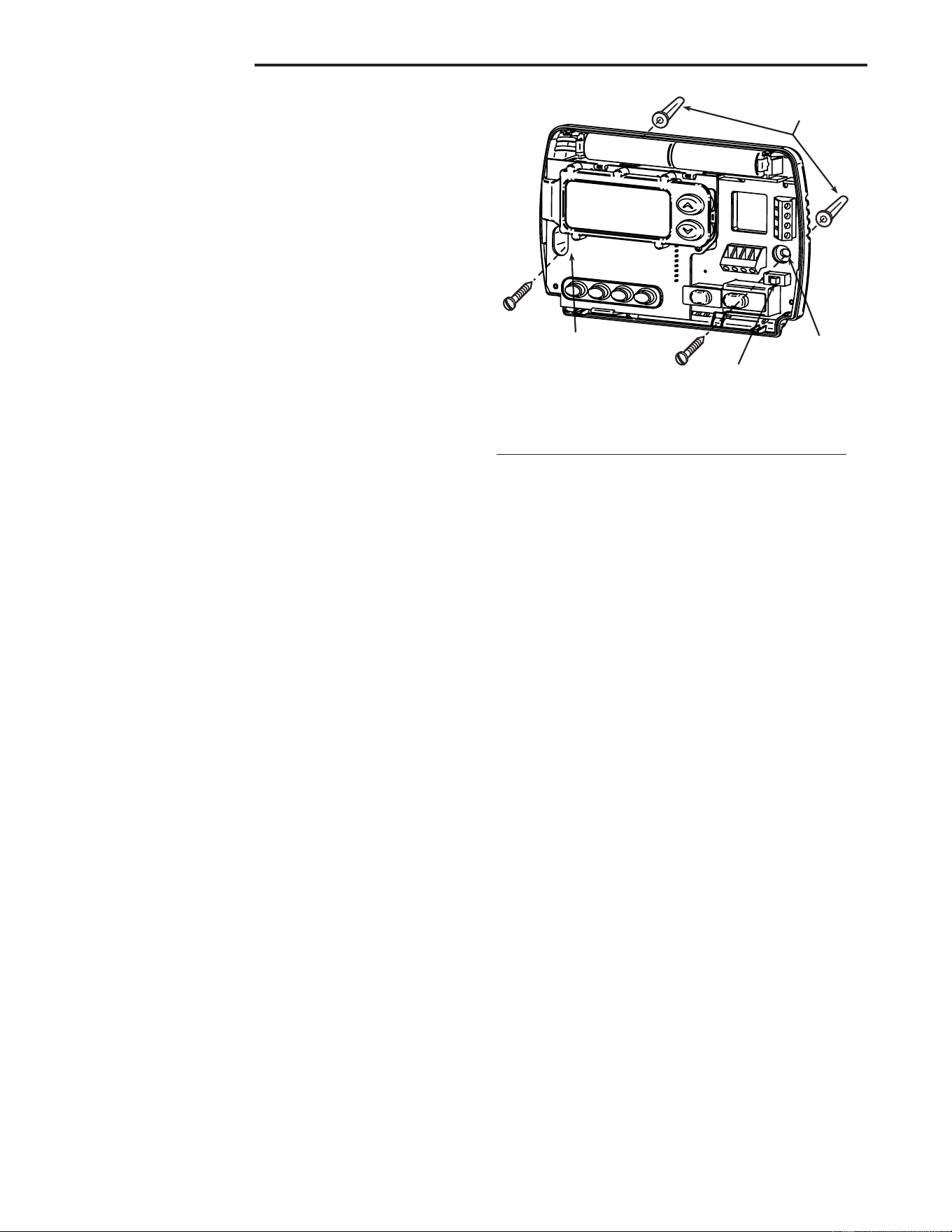
Mounting
holes
Mounting
holes
Electric/Gas
switch
Screw anchors
INSTALLATIONINSTALLATION
INSTALLATIONINSTALLATION
INSTALLATION
REMOVE OLD THERMOSTATREMOVE OLD THERMOSTAT
REMOVE OLD THERMOSTATREMOVE OLD THERMOSTAT
REMOVE OLD THERMOSTAT
1. Shut off electricity at the main fuse box until installation is
complete. Ensure that electrical power is disconnected.
2. Remove the front cover of the old thermostat.
With wiresWith wires
With wiresWith wires
With wires
still attached, still attached,
still attached, still attached,
still attached, remove wall plate from the wall. If the old
thermostat has a wall mounting plate, remove the thermo-
stat and the wall mounting plate as an assembly.
3.
Identify each wire attached to the old thermostat usingIdentify each wire attached to the old thermostat using
Identify each wire attached to the old thermostat usingIdentify each wire attached to the old thermostat using
Identify each wire attached to the old thermostat using
the labels enclosed with the new thermostat.the labels enclosed with the new thermostat.
the labels enclosed with the new thermostat.the labels enclosed with the new thermostat.
the labels enclosed with the new thermostat.
4. Disconnect the wires from old thermostat one at a time.
DODO
DODO
DO
NOT LET WIRES FALL BACK INTO THE WALL.NOT LET WIRES FALL BACK INTO THE WALL.
NOT LET WIRES FALL BACK INTO THE WALL.NOT LET WIRES FALL BACK INTO THE WALL.
NOT LET WIRES FALL BACK INTO THE WALL.
5. Install new thermostat using the following procedures.
ATTENTION!ATTENTION!
ATTENTION!ATTENTION!
ATTENTION!
This product does not contain mercury. However, this product
may replace a unit which contains mercury.
Do not open mercury cells. If a cell becomes damaged, do not
touch any spilled mercury. Wearing nonabsorbent gloves, take
up the spilled mercury with sand or other absorbent material and
place into a container which can be sealed. If a cell becomes
damaged, the unit should be discarded.
Mercury must not be discarded in household trash. When the
unit this product is replacing is to be discarded, place in a
suitable container and return to White-Rodgers at 2895 Harrison
Street, Batesville, AR 72501 for proper disposal.
ELECTRIC HEAT OR SINGLE-STAGEELECTRIC HEAT OR SINGLE-STAGE
ELECTRIC HEAT OR SINGLE-STAGEELECTRIC HEAT OR SINGLE-STAGE
ELECTRIC HEAT OR SINGLE-STAGE
HEAT PUMP SYSTEMSHEAT PUMP SYSTEMS
HEAT PUMP SYSTEMSHEAT PUMP SYSTEMS
HEAT PUMP SYSTEMS
This thermostat is configured from the factory to operate a heat/
cool, fossil fuel (gas, oil, etc.), forced air system. It is configured
correctly for any system that DOES NOT require the thermostat
to energize the fan on a call for heat. If your system is an electric
heat or heat-pump system that REQUIRES the thermostat to
turn on the fan on a call for heat, locate the
ELECTRIC/GASELECTRIC/GAS
ELECTRIC/GASELECTRIC/GAS
ELECTRIC/GAS
switch switch
switch switch
switch on the back of the thermostat (see fig. 1) and switch it to
the
ELECTRIC ELECTRIC
ELECTRIC ELECTRIC
ELECTRIC position. This will allow the thermostat to
energize the fan immediately on a call for heat. If you are unsure
if the heating/cooling system requires the thermostat to control
the fan, contact a qualified heating and air conditioning service
person.
ATTACH THERMOSTAT BASE TO WALLATTACH THERMOSTAT BASE TO WALL
ATTACH THERMOSTAT BASE TO WALLATTACH THERMOSTAT BASE TO WALL
ATTACH THERMOSTAT BASE TO WALL
1. Remove the packing material from the thermostat. Gently
pull the cover straight off the base. Forcing or prying on the
thermostat will cause damage to the unit. If necessary, move
the electric heat switch (see
ELECTRIC HEAT SYSTEMSELECTRIC HEAT SYSTEMS
ELECTRIC HEAT SYSTEMSELECTRIC HEAT SYSTEMS
ELECTRIC HEAT SYSTEMS,
above).
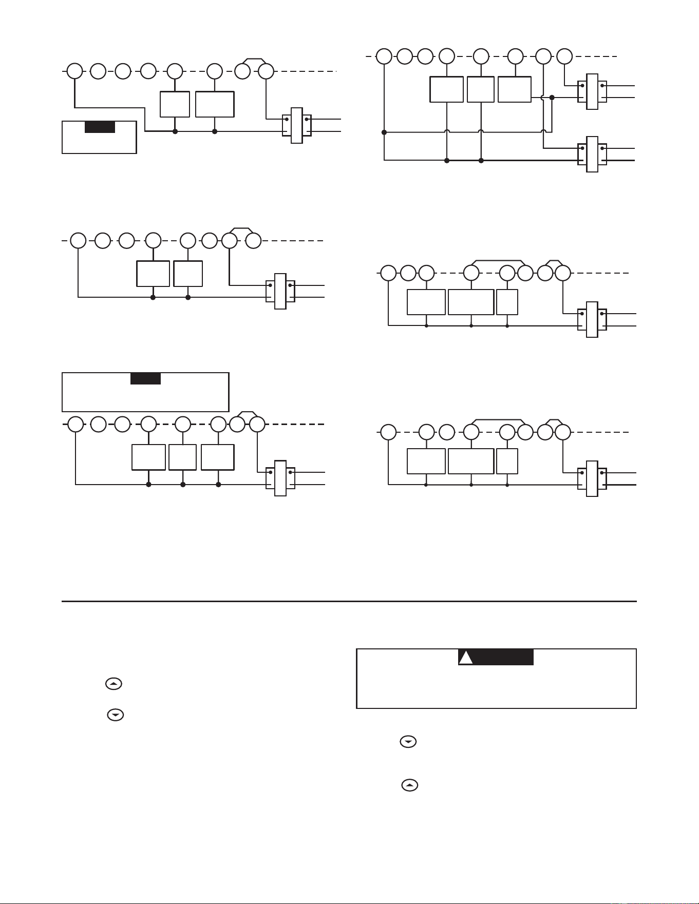
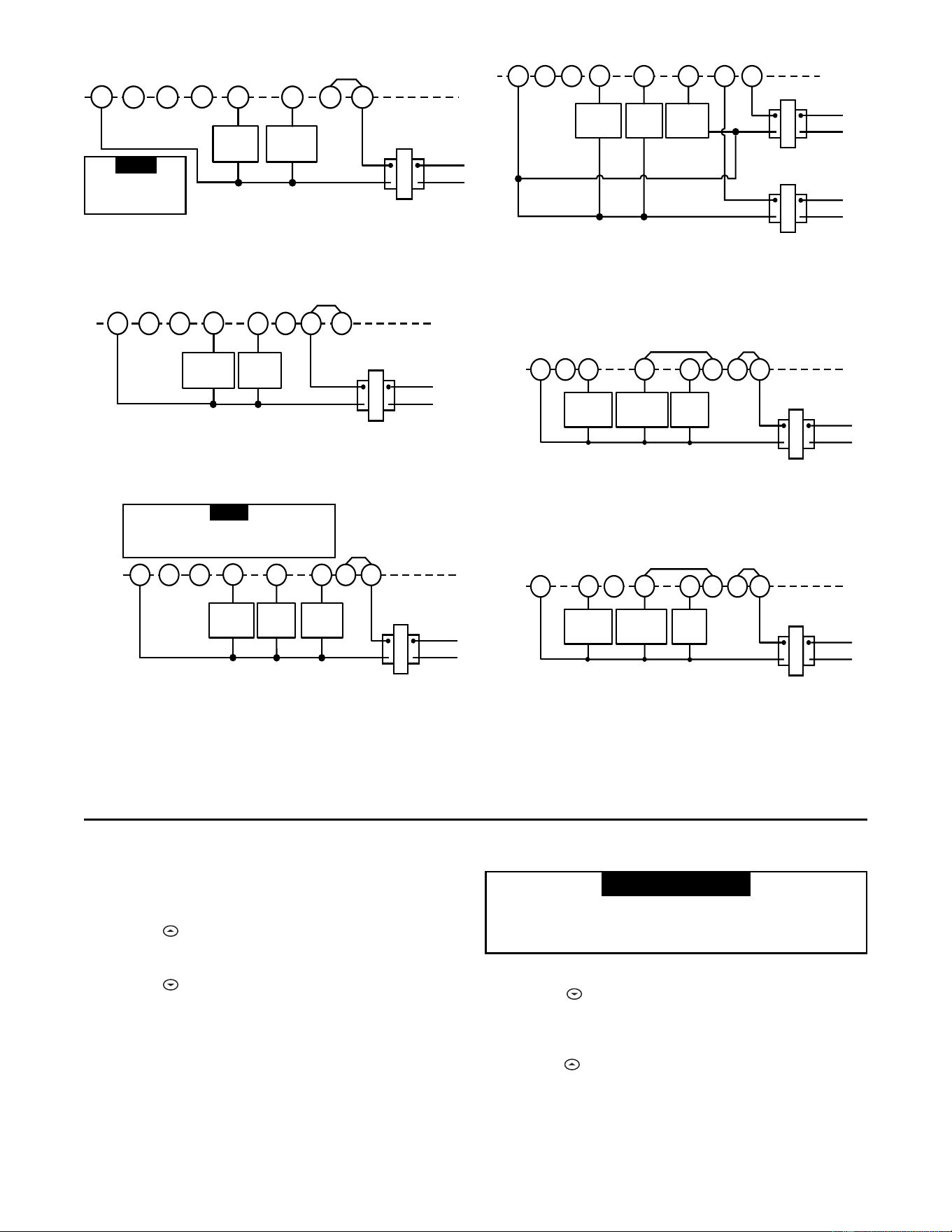
2. Connect wires beneath terminal screws on base using
appropriate wiring schematic (see figs. 2 through 7).
3. Place base over hole in wall and mark mounting hole
locations on wall using base as a template.
4. Move base out of the way. Drill mounting holes.
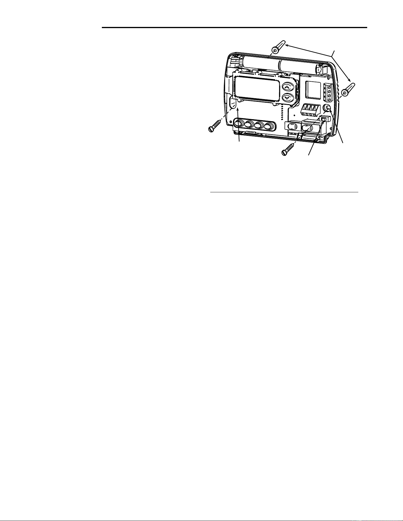
5. Fasten base loosely to wall, as shown in fig. 1, using two
mounting screws. Place a level against bottom of base,
adjust until level, and then tighten screws. (Leveling is for
appearance only and will not affect thermostat operation.) If
you are using existing mounting holes, or if holes drilled are
too large and do not allow you to tighten base snugly, use
plastic screw anchors to secure subbase.
6. Push excess wire into wall and plug hole with a fire-resistant
material (such as fiberglass insulation) to prevent drafts
from affecting thermostat operation.
BATTERY LOCATIONBATTERY LOCATION
BATTERY LOCATIONBATTERY LOCATION
BATTERY LOCATION
2 "AA" alkaline batteries are included in the thermostat at the
factory with a battery tag to prevent power drainage.
You mustYou must
You mustYou must
You must
remove the battery tag to engage the batteriesremove the battery tag to engage the batteries
remove the battery tag to engage the batteriesremove the battery tag to engage the batteries
remove the battery tag to engage the batteries.
If
“BATT”“BATT”
“BATT”“BATT”
“BATT” is displayed, the batteries are low and should be
replaced. For best results, replace all batteries with new pre-
mium brand alkaline batteries such as Duracell
®
or Energizer
®
.
To replace batteries, install the batteries along the top of the
base (see Fig. 1). The batteries must be installed with the
positive (+) end to the left.
HYDRONIC (HOT WATER OR STEAM)HYDRONIC (HOT WATER OR STEAM)
HYDRONIC (HOT WATER OR STEAM)HYDRONIC (HOT WATER OR STEAM)
HYDRONIC (HOT WATER OR STEAM)
HEATING SYSTEMSHEATING SYSTEMS
HEATING SYSTEMSHEATING SYSTEMS
HEATING SYSTEMS
This thermostat is set to operate properly with a forced-air
heating system. If you have a hydronic heating system (a
system that heats with hot water or steam), you must set the
thermostat to operate properly with your system. Change the
second option in the configuration menu to SL (see CONFIGU-
RATION MENU, page 4).
CHECK THERMOSTAT OPERATIONCHECK THERMOSTAT OPERATION
CHECK THERMOSTAT OPERATIONCHECK THERMOSTAT OPERATION
CHECK THERMOSTAT OPERATION
If at any time during testing your system does not operate
properly, contact a qualified service person.
Turn on power to the system.
Fan OperationFan Operation
Fan OperationFan Operation
Fan Operation
If your system
does notdoes not
does notdoes not
does not have a
GG
GG
G terminal connection, skip to
Heating SystemHeating System
Heating SystemHeating System
Heating System.
1. Move FAN switch to ON position. The blower should begin
to operate.
2. Move FAN switch to
AUTO AUTO
AUTO AUTO
AUTO position. The blower should
stop immediately.
Figure 1. Thermostat BaseFigure 1. Thermostat Base
Figure 1. Thermostat BaseFigure 1. Thermostat Base
Figure 1. Thermostat Base
3
RH
24 VAC
120 VAC
Hot
Neutral
THERMOSTAT
SYSTEM
G W
Figure 2. Typical wiring diagram for
heat only, 3-wire, single transformer systems
TRANSFORMER
Heating
System
Fan
Relay
YC
‡
RC
JUMPER
WIRE
OB
For 2-wire Heat only,
attach to RH and W
NOTE
RH
Y
24 VAC
120 VAC
Hot
Neutral
TRANSFORMER
THERMOSTAT
SYSTEM
G W
Figure 3. Typical wiring diagram for
cool only, 3-wire, single transformer systems
Cooling
System
Fan
Relay
RCOB
C
‡
JUMPER
WIRE
RH
Y
24 VAC
120 VAC
Hot
Neutral
THERMOSTAT
SYSTEM
G W
Figure 4. Typical wiring diagram for
heat/cool, 4-wire, single transformer systems
TRANSFORMER
Heating
System
Fan
Relay
Cooling
System
RC
JUMPER
WIRE
OC
‡
B
RED jumper wire (provided with thermostat) must be
connected between thermostat RH and RC terminals
for proper thermostat operation with this system.
NOTE
RH
Y
24 VAC
120 VAC
Hot
Neutral
THERMOSTAT
SYSTEM
G W
Figure 5. Typical wiring diagram for
heat/cool, 5-wire, two-transformer systems
HEATING
TRANSFORMER
Heating
System
Fan
Relay
Cooling
System
RC
24 VAC
120 VAC
Hot
Neutral
COOLING TRANSFORMER
OBC
‡
RH
Y
24 VAC
120 VAC
Hot
Neutral
THERMOSTAT
SYSTEM
G W
Figure 6. Typical wiring diagram for heat pump
with reversing valve energized in COOL
TRANSFORMER
Reversing
Valve*
RCOBC
‡
JUMPER
WIRE
Compressor
Contactor
JUMPER
WIRE
* Reversing valve is energized when the
system switch is in the COOL position
Fan
Relay
RH
Y
24 VAC
120 VAC
Hot
Neutral
THERMOSTAT
SYSTEM
G W
Figure 7. Typical wiring diagram for heat pump
with reversing valve energized in HEAT
TRANSFORMER
Reversing
Valve*
RCO
B
C
‡
JUMPER
WIRE
Compressor
Contactor
JUMPER
WIRE
* Reversing valve is energized when the
system switch is in the HEAT position
Fan
Relay
‡
The 24 Volt neutral connection to terminal C on the thermostat is not required if the batteries are replaced once a year
with fresh premium brand alkaline batteries.
Heating SystemHeating System
Heating SystemHeating System
Heating System
1. Move SYSTEM switch to
HEATHEAT
HEATHEAT
HEAT position. If the heating
system has a standing pilot, be sure to light it.
2. Press to adjust thermostat setting above room tempera-
ture. The heating system should begin to operate.
3. Press
to adjust temperature setting below room tem-
perature. The heating system should stop operating.
To prevent compressor and/or property damage, if theTo prevent compressor and/or property damage, if the
To prevent compressor and/or property damage, if theTo prevent compressor and/or property damage, if the
To prevent compressor and/or property damage, if the
outdoor temperature is below 50°F, DO NOT operateoutdoor temperature is below 50°F, DO NOT operate
outdoor temperature is below 50°F, DO NOT operateoutdoor temperature is below 50°F, DO NOT operate
outdoor temperature is below 50°F, DO NOT operate
the cooling system.the cooling system.
the cooling system.the cooling system.
the cooling system.
1. Move SYSTEM switch to
COOLCOOL
COOLCOOL
COOL position.
2. Press
to adjust thermostat setting below room tempera-
ture. The blower should come on immediately on high
speed, followed by cold air circulation
3. Press to adjust temperature setting above room tem-
perature. The cooling system should stop operating.
Cooling SystemCooling System
Cooling SystemCooling System
Cooling System
▲
CAUTION
!
4
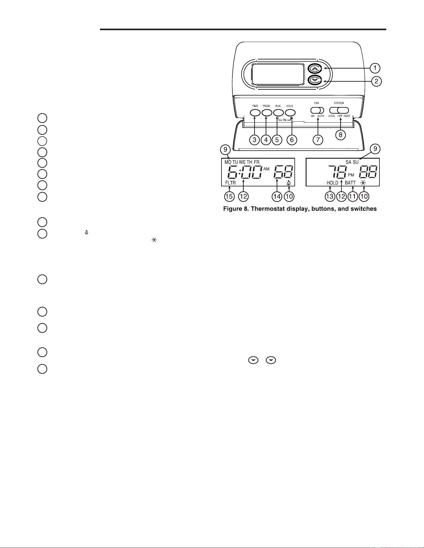
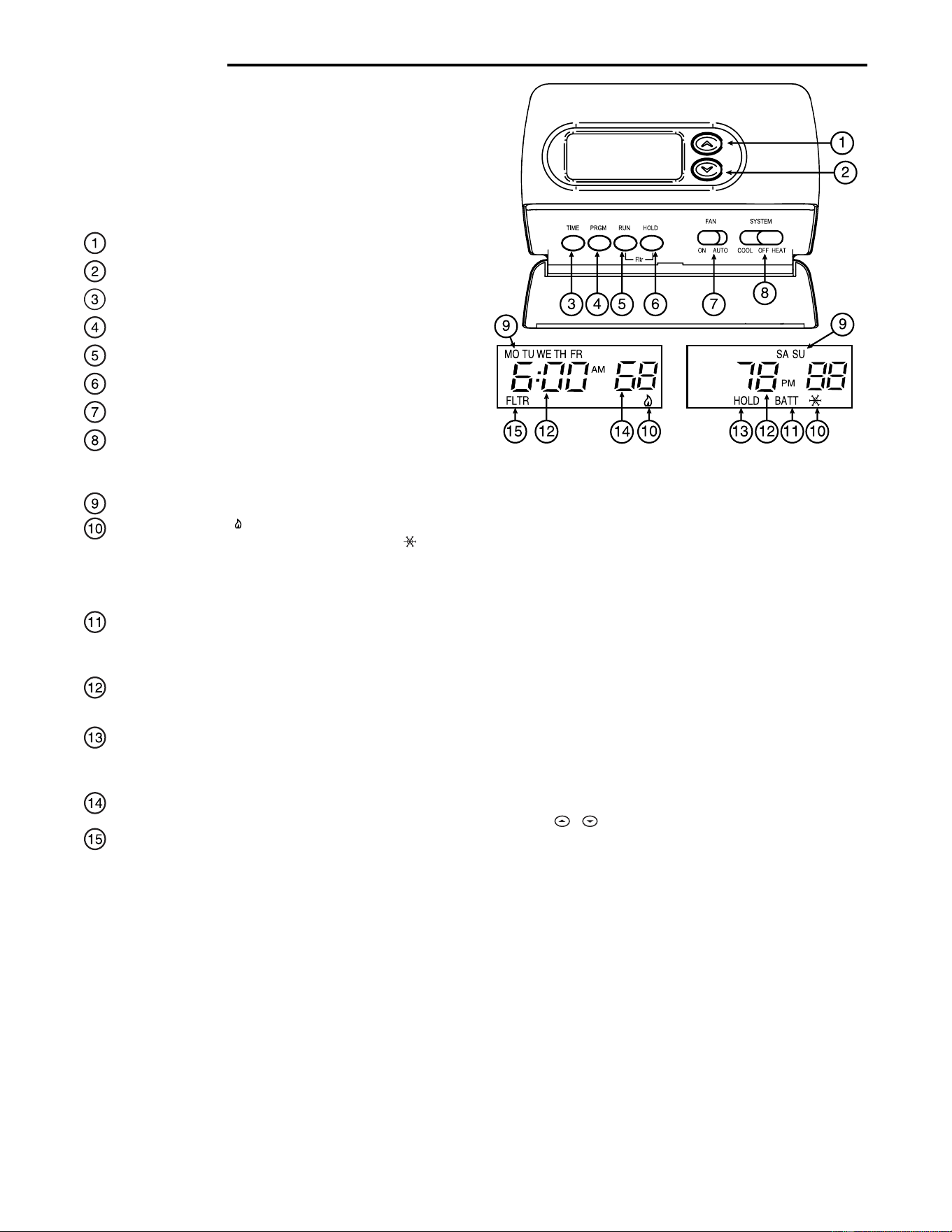
Before you begin programming your thermostat, you should be
familiar with its features and with the display and the location
and operation of the thermostat buttons. Your thermostat con-
sists of two parts: the
thermostat coverthermostat cover
thermostat coverthermostat cover
thermostat cover and the
basebase
basebase
base. To remove
the cover, pull it straight out from the base. To replace the cover,
line up the cover with the base and press until the cover snaps
onto the base.
The Thermostat Buttons The Thermostat Buttons
The Thermostat Buttons The Thermostat Buttons
The Thermostat Buttons
and Switchesand Switches
and Switchesand Switches
and Switches
1
Raises temperature setting.
2
Lowers temperature setting.
3
TIME button.
4
PRGM (program) button.
5
RUN (run program) button.
6
HOLD temperature button.
7
FAN switch (
ONON
ONON
ON,
AUTOAUTO
AUTOAUTO
AUTO).
8
SYSTEM switch (
COOLCOOL
COOLCOOL
COOL,
OFFOFF
OFFOFF
OFF,
HEATHEAT
HEATHEAT
HEAT).
The DisplayThe Display
The DisplayThe Display
The Display
9
Indicates day of the week.
10
Flame iconFlame icon
Flame iconFlame icon
Flame icon ( ) is displayed when the SYSTEM switch is in
the HEAT position.
Snowflake iconSnowflake icon
Snowflake iconSnowflake icon
Snowflake icon ( )is displayed (non-
flashing) when the SYSTEM switch is in the COOL position.
SnowflakeSnowflake
SnowflakeSnowflake
Snowflake is displayed (flashing) if the thermostat is in
lockout mode to prevent the compressor from cycling too
quickly.
11
Displays
“BATT”“BATT”
“BATT”“BATT”
“BATT” when the 2 "AA" batteries are low and
should be replaced. Only
“BATT”“BATT”
“BATT”“BATT”
“BATT” and
“LO”“LO”
“LO”“LO”
“LO” in the minutes
field are displayed when batteries are low with no system
power.
12
Alternately displays current time and temperature. Dis-
plays
“LO”“LO”
“LO”“LO”
“LO” in the minutes field when batteries are low.
13
The word
“HOLD”“HOLD”
“HOLD”“HOLD”
“HOLD” is displayed when the thermostat is in the
HOLD mode.
“HOLD”“HOLD”
“HOLD”“HOLD”
“HOLD” is displayed flashing when the
thermostat is in a temporary HOLD Mode.
14
Displays currently programmed set temperature (this is
blank when SYSTEM switch is in the
OFFOFF
OFFOFF
OFF position).
15
Displays
“FLTR”“FLTR”
“FLTR”“FLTR”
“FLTR” when the system has run for the pro-
grammed filter time period as a reminder to change or clean
your air filter.
CONFIGURATION MENUCONFIGURATION MENU
CONFIGURATION MENUCONFIGURATION MENU
CONFIGURATION MENU
The configuration menu allows you to set certain thermostat
operating characteristics to your system or personal require-
ments.
Press RUN to make sure the thermostat is in the run program
mode, then press PRGM and RUN at the same time to enter the
configuration menu. The display will show the first item in the
configuration menu.
The configuration menu table summarizes the configuration
options. An explanation of each option follows.
OPERATIONOPERATION
OPERATIONOPERATION
OPERATION
Press HOLD to change to the next menu item or press TIME to
go backwards to the previous item in the menu. To exit the menu
and return to the program operation, press RUN. If no keys are
pressed within fifteen minutes, the thermostat will revert to
normal operation.
1)1)
1)1)
1)
Select Temporary Hold Time Select Temporary Hold Time
Select Temporary Hold Time Select Temporary Hold Time
Select Temporary Hold Time - The thermostat can hold any
temperature you set it to for the amount of time you select on
this option. Your choices are 0:00 to 8:00 hours in 15 minute
increments. 0:00 disables the function
Example:
1. You have selected 3:00 hours for the Temporary Hold
time period.
2. With the thermostat set to Heat or Cool, press HOLD
forfor
forfor
for
approximately five secondsapproximately five seconds
approximately five secondsapproximately five seconds
approximately five seconds until HOLD time (3:00
indicating 3 hours) appears as a setting reminder.
3. After releasing the button,
“HOLD”“HOLD”
“HOLD”“HOLD”
“HOLD” on the display will
blink.
4. Use
or to set the temperature to your preference.
The thermostat will maintain this temperature setting for
3 hours with
“HOLD”“HOLD”
“HOLD”“HOLD”
“HOLD” blinking to remind you it is in
Temporary Hold. After 3 hours the thermostat will go
back to the program temperature and
“HOLD”“HOLD”
“HOLD”“HOLD”
“HOLD” will no
longer blink or display.
2)2)
2)2)
2)
Select FA or SL (Fast or Slow) Heating Cycle RateSelect FA or SL (Fast or Slow) Heating Cycle Rate
Select FA or SL (Fast or Slow) Heating Cycle RateSelect FA or SL (Fast or Slow) Heating Cycle Rate
Select FA or SL (Fast or Slow) Heating Cycle Rate - The
FA setting is frequently used for gas, oil or electric heat. The
SL setting produces a longer heating cycle which is nor-
mally for hot water or steam (hydronic) systems. Both
settings produce very accurate temperature control and
can be set to your personal preference. FA cycles the
system just under 1°F and the SL setting cycles at approxi-
mately 1.5°F.
3)3)
3)3)
3)
Select backlit displaySelect backlit display
Select backlit displaySelect backlit display
Select backlit display - The display backlight improves
display contrast in low lighting conditions. Selecting back-
light
ONON
ONON
ON will keep the light on for a short period of time after
any key is pressed. Selecting
OFFOFF
OFFOFF
OFF will keep the light off.
5
4)4)
4)4)
4)
Select Energy Management Recovery OFF or ONSelect Energy Management Recovery OFF or ON
Select Energy Management Recovery OFF or ONSelect Energy Management Recovery OFF or ON
Select Energy Management Recovery OFF or ON -
Energy Management Recovery (EMR) causes the thermo-
stat to start heating or cooling early to make the building
temperature reach the program setpoint at the time you
specify. Heating will start 5 minutes early for every 1° of
temperature required to reach setpoint.
Example:Example:
Example:Example:
Example: You select EMR and have your heating pro-
grammed to 65° at night and 70° at 7 AM. If the building
temperature is 65° the difference between 65° and 70° is
5°. Allowing 5 minutes per degree the thermostat setpoint
will change to 70° at 6:35 AM. Cooling allows more time per
degree because it takes longer to reach temperature.
5)5)
5)5)
5)
Select filter replacement run timeSelect filter replacement run time
Select filter replacement run timeSelect filter replacement run time
Select filter replacement run time - The thermostat will
display
“FLTR” “FLTR”
“FLTR” “FLTR”
“FLTR” after a set time of operation. This is a
reminder to change or clean your air filter. This time can be
set from 0 to 1950 hours in 50 hour increments.
A selectionA selection
A selectionA selection
A selection
of 000 will cancel this feature.of 000 will cancel this feature.
of 000 will cancel this feature.of 000 will cancel this feature.
of 000 will cancel this feature. When
“FLTR”“FLTR”
“FLTR”“FLTR”
“FLTR” is displayed,
you can clear it by pressing HOLD and RUN at the same
time. This resets the timer and starts counting the hours
until the next filter change. Changing the time in the menu
also resets the timer.
6)6)
6)6)
6)
Select Compressor Lockout LOC OFF or ONSelect Compressor Lockout LOC OFF or ON
Select Compressor Lockout LOC OFF or ONSelect Compressor Lockout LOC OFF or ON
Select Compressor Lockout LOC OFF or ON - Selecting
LOC ON will cause the thermostat to wait 5 minutes before
turning on the compressor if the heating and cooling sys-
tem loses power. It will also wait 5 minutes minimum
between cooling cycles. This is intended to help protect the
compressor from short cycling. Some newer compressors
already have a time delay built in and do not require this
feature. Your compressor manufacturer can tell you if the
feature is already present in their system. When the com-
pressor time delay occurs it will flash the (snowflake icon)
for about five minutes then turn on the compressor.
7)7)
7)7)
7)
Select Temperature Display Adjustment 4 LO to 4 HISelect Temperature Display Adjustment 4 LO to 4 HI
Select Temperature Display Adjustment 4 LO to 4 HISelect Temperature Display Adjustment 4 LO to 4 HI
Select Temperature Display Adjustment 4 LO to 4 HI -
Allows you to adjust the room temperature display 4° higher
or lower. Your thermostat was accurately calibrated at the
factory but you have the option to change the display
temperature to match your previous thermostat.
8)8)
8)8)
8)
Select F° or C° Readout
Select F° or C° Readout
Select F° or C° ReadoutSelect F° or C° Readout
Select F° or C° Readout - Changes the display readout to
Centigrade or Fahrenheit as required.
OPERATING FEATURESOPERATING FEATURES
OPERATING FEATURESOPERATING FEATURES
OPERATING FEATURES
Now that you are familiar with the thermostat buttons and
display, read the following information to learn about the many
features of the thermostat.
•
SIMULTANEOUS HEATING/COOLING PROGRAMSIMULTANEOUS HEATING/COOLING PROGRAM
SIMULTANEOUS HEATING/COOLING PROGRAMSIMULTANEOUS HEATING/COOLING PROGRAM
SIMULTANEOUS HEATING/COOLING PROGRAM
STORAGE STORAGE
STORAGE STORAGE
STORAGE — When programming, you can enter both
your heating and cooling programs at the same time. There
is no need to reprogram the thermostat at the beginning of
each season.
•
TEMPERATURE OVERRIDETEMPERATURE OVERRIDE
TEMPERATURE OVERRIDETEMPERATURE OVERRIDE
TEMPERATURE OVERRIDE — Press
or until the
display shows the temperature you want. The thermostat
will override current programming and keep the room
temperature at the selected temperature until the next
program period begins. Then the thermostat will automati-
cally revert to the program.
•
HOLD TEMPERATUREHOLD TEMPERATURE
HOLD TEMPERATUREHOLD TEMPERATURE
HOLD TEMPERATURE — The thermostat can hold any
temperature within its range for an indefinite period without
reverting to the programmed temperature. Momentarily
press HOLD button.
“HOLD”“HOLD”
“HOLD”“HOLD”
“HOLD” will be displayed. Then choose
the desired temperature by pressing
or . The
thermostat will hold the room temperature at the selected
setting until you press RUN button to start program opera-
tion again.
•
CONFIGURATION MENUCONFIGURATION MENU
CONFIGURATION MENUCONFIGURATION MENU
CONFIGURATION MENU — Allows you to customize
certain thermostat options.
PROGRAMMING YOUR THERMOSTATPROGRAMMING YOUR THERMOSTAT
PROGRAMMING YOUR THERMOSTATPROGRAMMING YOUR THERMOSTAT
PROGRAMMING YOUR THERMOSTAT
This section will help you plan your thermostat’s program to
meet your needs. For maximum comfort and efficiency, keep
the following guidelines in mind when planning your program.
• When heating (cooling) your building, program the
temperatures to be cooler (warmer) when the building is
vacant or during periods of low activity.
• During early morning hours, the need for cooling is
usually minimal.
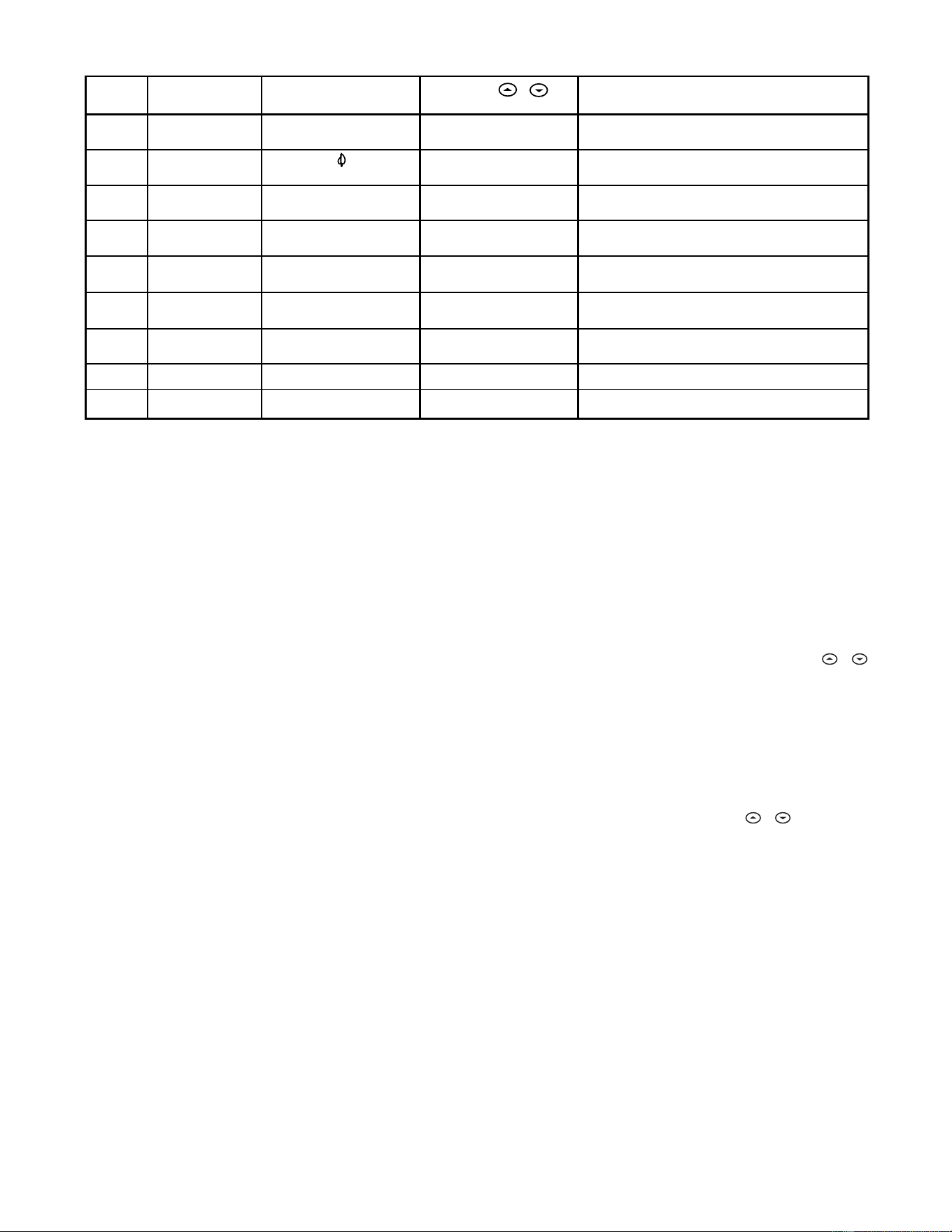
1
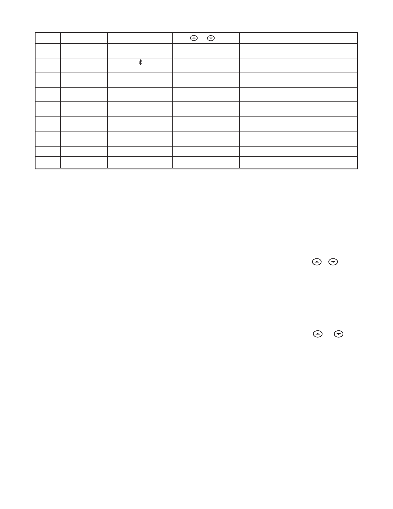
Step Press Button(s) Displayed (Factory Default) Press or to select: COMMENTS
HOLD
(0:00)
0 to 8 hrs (in
15 minute increments)
2
(FA)
SL
Select temporary Hold time
4
5
E
(ON)
OFF
6
7
LOC
(OFF)
ON
0 HI
(0)
4 LO to
4 HI
(F) C
Returns to normal operation
8
9
Select Energy Management Recovery OFF or ON
Select compressor lockout OFF or ON
Select temperature display adjustment higher or lower
Select temperature display to F or C
RUN
PRGM
and RUN
HOLD
*
HOLD
*
3
d-L
(ON)
OFF
Select display backlight OFF or ON
HOLD
*
HOLD
*
Filter
(000)
0 to 1950 hours
(in 50 hour increments)
Select filter replacement run time
HOLD
*
HOLD
*
HOLD
*
Select FA or SL (Fast or Slow) heating cycle rate
Configuration Menu
* Press
HOLD to advance to next item or TIME to move backwards to previous item
6
Enter Heating ProgramEnter Heating Program
Enter Heating ProgramEnter Heating Program
Enter Heating Program
1. Move the SYSTEM switch to
HEATHEAT
HEATHEAT
HEAT.
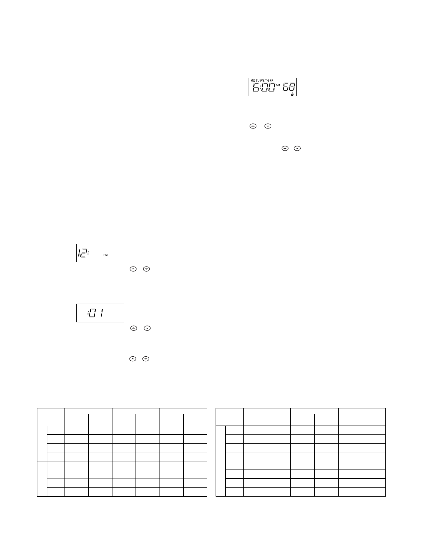
2. Press PRGM once. “
MO TU WE TH FRMO TU WE TH FR
MO TU WE TH FRMO TU WE TH FR
MO TU WE TH FR” (indicating week-
day program) will appear in the display. Also displayed are
the currently programmed start time for the
1st heating1st heating
1st heating1st heating
1st heating
period and the currently programmed temperature (flash-
ing).
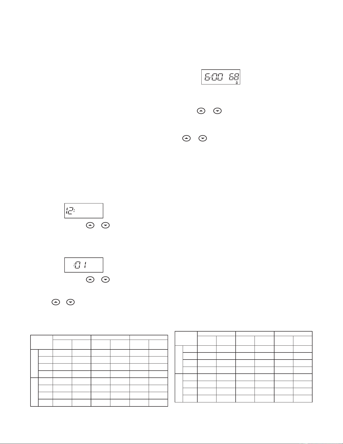
EXAMPLE:
AM
MO TU WE TH FR
This display window shows that for the 1st weekday period,
the start time is 6:00 AM, and 68° is the programmed
temperature (this example reflects factory preprogramming).
3. Press or to change the displayed temperature to
your selected temperature for the 1st heating program
period.
4. Press TIME once (the programmed time will flash). Press
or until your selected time appears. The time will
change in 15 minute increments. When your selected time
is displayed, press TIME again to return to the change
temperature mode.
5. Press PRGM once. The currently programmed start time
and setpoint temperature for the
2nd heating2nd heating
2nd heating2nd heating
2nd heating program
period will appear.
6. Repeat steps 3 and 4 to select the start time and heating
temperature for the 2nd heating program period.
7. Repeat steps 3 through 5 for the 3rd and 4th heating
program periods. Weekday heating programs are now com-
plete.
8. Press PRGM once. “
SASA
SASA
SA” (indicating Saturday program) will
appear in the display, along with the start time for the 1st
heating period and the currently programmed temperature.
9. Repeat steps 3 through 7 to complete Saturday heating
programming.
10.Press PRGM once. “
SUSU
SUSU
SU” (indicating Sunday program) will
appear in the display, along with the start time for the 1st
heating period and the currently programmed temperature.
11.Repeat steps 3 through 7 to complete Sunday heating
programming.
12.When you have completed entering your heating program,
press RUN.
Planning Your ProgramPlanning Your Program
Planning Your ProgramPlanning Your Program
Planning Your Program
Look at the factory preprogrammed times and temperatures
shown in the sample schedule. If this program will suit your
needs, simply press the RUN button to begin running the factory
preset program.
If you want to change the preprogrammed times and tempera-
tures, follow these steps.
Determine the time periods and temperatures for your weekday
and weekend programs. You must program four periods for
both the weekday and weekend program. However, you may
use the same heating and cooling temperatures for consecutive
time periods. You can choose start times, heating tempera-
tures, and cooling temperatures independently for both week-
day and weekend programs (for example, you may select 5:00
AM and 70° as the weekday
1st period heating1st period heating
1st period heating1st period heating
1st period heating start time and
temperature, and also choose 7:00 AM and 76° as the weekday
1st period cooling1st period cooling
1st period cooling1st period cooling
1st period cooling start time and temperature).
Use the following table to plan your program time periods and
the temperatures you want during each period. Fill in the
complete table to have a record of your programs.
Entering Your ProgramEntering Your Program
Entering Your ProgramEntering Your Program
Entering Your Program
Follow these steps to enter the heating and cooling programs
you have selected.
Set Current Time and DaySet Current Time and Day
Set Current Time and DaySet Current Time and Day
Set Current Time and Day
1. Press TIME button once. The display will show the hour only.
EXAMPLE:
PM
2. Press and hold either or until you reach the correct
hour and AM/PM designation (
AMAM
AMAM
AM begins at midnight;
PMPM
PMPM
PM
begins at noon).
3. Press TIME once. The display window will show the minutes
only.
EXAMPLE:
4. Press and hold either or until you reach the correct
minutes.
5. Press TIME once. The display will show the day of the week.
6. Press or until you reach the current day of the week.
7. Press RUN once. The display will show the correct time and
room temperature alternately.
WEEKDAY (5 DAY)
SATURDAY (1 DAY)
Start
Time Temperature
Start
Time Temperature
1ST 6:00 AM 70°F 6:00 AM 70°F 6:00 AM 70°F
2ND 8:00 AM 62°F 8:00 AM 62°F 8:00 AM 62°F
3RD 5:00 PM 70°F 5:00 PM 70°F 5:00 PM 70°F
4TH 10:00 PM 62°F 10:00 PM 62°F 10:00 PM 62°F
1ST 6:00 AM 78°F 6:00 AM 78°F 6:00 AM 78°F
2ND 8:00 AM 85°F 8:00 AM 85°F 8:00 AM 85°F
3RD 5:00 PM 78°F 5:00 PM 78°F 5:00 PM 78°F
4TH 10:00 PM 82°F 10:00 PM 82°F 10:00 PM 82°F
SAMPLE
Heating/Cooling Schedule Plan (Factory Program)
Period
SUNDAY (1 DAY)
Start
Time Temperature
COOL HEAT
WEEKDAY (5 DAY)
SATURDAY (1 DAY)
Start
Time Temperature
Start
Time Temperature
1ST
2ND
3RD
4TH
1ST
2ND
3RD
4TH
Heating/Cooling Schedule Plan
Period
SUNDAY (1 DAY)
Start
Time Temperature
COOL HEAT
7
If the outside temperature is below 50°F, disconnectIf the outside temperature is below 50°F, disconnect
If the outside temperature is below 50°F, disconnectIf the outside temperature is below 50°F, disconnect
If the outside temperature is below 50°F, disconnect
power to the cooling system before programming.power to the cooling system before programming.
power to the cooling system before programming.power to the cooling system before programming.
power to the cooling system before programming.
Energizing the air conditioner compressor during coldEnergizing the air conditioner compressor during cold
Energizing the air conditioner compressor during coldEnergizing the air conditioner compressor during cold
Energizing the air conditioner compressor during cold
weather may cause personal injury or property damage.weather may cause personal injury or property damage.
weather may cause personal injury or property damage.weather may cause personal injury or property damage.
weather may cause personal injury or property damage.
1. Move SYSTEM switch to
COOLCOOL
COOLCOOL
COOL position.
2. Follow the procedure for entering your cooling program,
using your selected cooling times and temperatures.
Enter Cooling ProgramEnter Cooling Program
Enter Cooling ProgramEnter Cooling Program
Enter Cooling Program
CHECK YOUR PROGRAMMINGCHECK YOUR PROGRAMMING
CHECK YOUR PROGRAMMINGCHECK YOUR PROGRAMMING
CHECK YOUR PROGRAMMING
Follow these steps to check your thermostat programming one
final time before beginning thermostat operation.
1. Move SYSTEM switch to
HEATHEAT
HEATHEAT
HEAT position.
2. Press PRGM to view the 1st weekday heating period time
and temperature. Each time you press PRGM, the next
heating period time and temperature will be displayed in
sequence for weekday, then weekend program periods (you
may change any time or temperature during this procedure).
3. Press RUN.
4. Move SYSTEM switch to
COOLCOOL
COOLCOOL
COOL position.
5. Repeat step 2 to check cooling program.
6. Move SYSTEM switch to
HEATHEAT
HEATHEAT
HEAT or
COOLCOOL
COOLCOOL
COOL and press RUN to
begin program operation.
YOUR THERMOSTAT IS NOW COMPLETELY PROGRAMMED ANDYOUR THERMOSTAT IS NOW COMPLETELY PROGRAMMED AND
YOUR THERMOSTAT IS NOW COMPLETELY PROGRAMMED ANDYOUR THERMOSTAT IS NOW COMPLETELY PROGRAMMED AND
YOUR THERMOSTAT IS NOW COMPLETELY PROGRAMMED AND
READY TO PROVIDE MAXIMUM COMFORT AND EFFICIENCY!READY TO PROVIDE MAXIMUM COMFORT AND EFFICIENCY!
READY TO PROVIDE MAXIMUM COMFORT AND EFFICIENCY!READY TO PROVIDE MAXIMUM COMFORT AND EFFICIENCY!
READY TO PROVIDE MAXIMUM COMFORT AND EFFICIENCY!
Reset OperationReset Operation
Reset OperationReset Operation
Reset Operation
If a voltage spike or static discharge blanks out the display or
causes erratic thermostat operation you can reset the thermo-
stat by pressing , and TIME at the same time. This also
resets the factory defaults to the configuration menu and
SymptomSymptom
SymptomSymptom
Symptom
PP
PP
P
ossibossib
ossibossib
ossib
le Causele Cause
le Causele Cause
le Cause
Corrective ActionCorrective Action
Corrective ActionCorrective Action
Corrective Action
No Heat/No Cool/No FanNo Heat/No Cool/No Fan
No Heat/No Cool/No FanNo Heat/No Cool/No Fan
No Heat/No Cool/No Fan
1. Blown fuse or tripped circuit breaker. Replace fuse or reset breaker.
(common problems)(common problems)
(common problems)(common problems)
(common problems)
2. Furnace power switch to OFF. Turn switch to ON.
3. Furnace blower compartment door or Replace door panel in proper position to engage
panel loose or not properly installed. safety interlock or door switch.
No HeatNo Heat
No HeatNo Heat
No Heat
1. Pilot light not lit. Re-light pilot.
2. SYSTEM Switch not set to
HEAHEA
HEAHEA
HEA
TT
TT
T. Set SYSTEM Switch to
Heat Heat
Heat Heat
Heat and raise setpoint
above room temperature.
3. Loose connection to thermostat or system. Verify thermostat and system wires are securely
attached.
4. Furnace Lock-Out Condition. Heat may also Many furnaces have safety devices that shut the
be intermittent. system down when a lock-out condition occurs.
If the heat works intermittently contact the furnace
manufacturer or local service person for assistance.
5. Heating System requires service or Diagonistic: Set SYSTEM Switch to
HEAHEA
HEAHEA
HEA
TT
TT
T and raise
thermostat requires replacement. the setpoint above room temperature. Within a few
seconds the thermostat should make a soft click
sound. This sound usually indicates the thermostat
is operating properly. If the thermostat does not
click, try the reset operation listed above. If the
thermostat does not click after being reset contact
your heating and cooling service person or place
of purchase for a replacement. If the thermostat
clicks, contact the furnace manufacturer or a
service person to verify the heating system is
operating correctly.
No CoolNo Cool
No CoolNo Cool
No Cool
1. SYSTEM Switch not set to
COOLCOOL
COOLCOOL
COOL Set SYSTEM Switch to
COOLCOOL
COOLCOOL
COOL and lower setpoint
below room temperature.
2. Loose connection to thermostat or system. Verify thermostat and system wires are securely
attached.
3. Cooling System requires service or thermostat Same procedure as diagnostic for No Heat
requires replacement. condition except set the thermostat to
COOLCOOL
COOLCOOL
COOL and
lower the setpoint below the room temperature.
There may be up to a five minute delay before
the thermostat clicks in Cooling if the compressor
lock-out option is selected in the configuration
menu (Item 6).
TROUBLESHOOTINGTROUBLESHOOTING
TROUBLESHOOTINGTROUBLESHOOTING
TROUBLESHOOTING
program. If the thermostat has power, has been reset and still
does not function correctly contact your heating/cooling ser-
vice person or place of purchase.
BatteriesBatteries
BatteriesBatteries
Batteries
For optimum performance, we recommend replacing batteries
once a year with fresh "AA" alkaline batteries.
CAUTION
!
SymptomSymptom
SymptomSymptom
Symptom
PP
PP
P
ossibossib
ossibossib
ossib
le Causele Cause
le Causele Cause
le Cause
Corrective ActionCorrective Action
Corrective ActionCorrective Action
Corrective Action
Heat, Cool or Fan Runs Constantly.Heat, Cool or Fan Runs Constantly.
Heat, Cool or Fan Runs Constantly.Heat, Cool or Fan Runs Constantly.
Heat, Cool or Fan Runs Constantly.
1. FAN Switch set to Fan ON. Check each wire connection to verify they are
2. Possible short in wiring. not shorted or touching together. No bare wire
3. Possible short in thermostat. should stick out from under terminal screws.
4. Possible short in Heat/Cool/Fan system. Try resetting the thermostat. If the condition
persists the manufacturer of your system
or service person can instruct you on how
to test the Heat/Cool system for correct
operation. If the system operates correctly,
replace the thermostat.
Furnace Cycles Too Fast or Too SlowFurnace Cycles Too Fast or Too Slow
Furnace Cycles Too Fast or Too SlowFurnace Cycles Too Fast or Too Slow
Furnace Cycles Too Fast or Too Slow
1. The location of the thermostat and/or the size Item 2 in the Configuration Menu is the adjustment
(narrow or wide temperature swing)(narrow or wide temperature swing)
(narrow or wide temperature swing)(narrow or wide temperature swing)
(narrow or wide temperature swing)
of the Heating System may be influencing the that controls the cycle rate. If an acceptable cycle
cycle rate. rate is not achieved using the FA (Fast) or SL
(Slow) adjustment contact a local service person for
additional suggestions.
Cooling Cycles Too Fast or Too SlowCooling Cycles Too Fast or Too Slow
Cooling Cycles Too Fast or Too SlowCooling Cycles Too Fast or Too Slow
Cooling Cycles Too Fast or Too Slow
1. The location of the thermostat and/or the size The cycle rate for cooling is fixed and can not be
(narrow or wide temperature swing)(narrow or wide temperature swing)
(narrow or wide temperature swing)(narrow or wide temperature swing)
(narrow or wide temperature swing)
of the Cooling System may be influencing the adjusted. Contact a local service person for
cycle rate. suggestions.
Thermostat Setting and ThermometerThermostat Setting and Thermometer
Thermostat Setting and ThermometerThermostat Setting and Thermometer
Thermostat Setting and Thermometer
1. Thermostat thermometer setting requires The thermometer can be adjusted +/- 4 degrees as
DisagreeDisagree
DisagreeDisagree
Disagree
adjustment. listed in item 7 of the Configuration Menu. No other
adjustment is possible.
Clock Loses or Gains TimeClock Loses or Gains Time
Clock Loses or Gains TimeClock Loses or Gains Time
Clock Loses or Gains Time
1. Loss of power to thermostat and low batteries. The thermostat will maintain its program in memory
even with no power/no batteries but the clock time
will be incorrect when power is restored. See No
Heat/No Cool/No Fan (common problems) above
for items to check in the system.
Heat or Cool Starts EarlyHeat or Cool Starts Early
Heat or Cool Starts EarlyHeat or Cool Starts Early
Heat or Cool Starts Early
1. EMR activated See Configuration Menu (Item 4).
Thermostat Does Not Follow ProgramThermostat Does Not Follow Program
Thermostat Does Not Follow ProgramThermostat Does Not Follow Program
Thermostat Does Not Follow Program
1. AM or PM set incorrectly in program. Check current clock and program settings including
2. AM or PM set incorrectly on the clock. the AM or PM designations for each time period.
3. Voltage spike or static discharge. If a voltage spike or static discharge occurs use the
Reset Operation listed above.
Blank Display and/or Keypad NotBlank Display and/or Keypad Not
Blank Display and/or Keypad NotBlank Display and/or Keypad Not
Blank Display and/or Keypad Not
1. Loss of power and dead batteries. Replace batteries and check heat/cool system for
RespondingResponding
RespondingResponding
Responding
2. Voltage Spike or Static Discharge. proper operation. If a voltage spike or static discharge
occurs use the Reset Operation listed above.
TROUBLESHOOTINGTROUBLESHOOTING
TROUBLESHOOTINGTROUBLESHOOTING
TROUBLESHOOTING
www.white-rodgers.com
St. Louis, Missouri Markham, Ontario
The Emerson logo is a
trademark and service mark
of Emerson Electric Co.
HOMEOWNER HELP LINE: 1-800-284-2925
1F80-361
Termostato digital electrónico programable
INSTRUCCIONES DE
INSTALACIÓN Y OPERACIÓN
EL NO LEER Y SEGUIR CON CUIDADO TODAS LAS INSTRUCCIONES
ANTES DE INSTALAR O UTILIZAR ESTE CONTROL PODRÍA CAUSAR
LESIONES PERSONALES Y/O DAÑOS MATERIALES.
DESCRIPCIÓN
• Omisióndelatemperaturaprogramadahastaelsiguiente
período de programación
• Omisióndelprogramamanual(MANTENERtemperatura)
• MANTENERtemperaturadeformatemporal
• Convertibilidadde°Fa°C
• Rangodetemperaturade45°a90°F
• TerminalesRC,RH,C,W,Y,G,OyB
• TerminalCopcional(opcióndedoblealimentación)
• TerminalesByOparabombasdecalordeunasolaetapa
(sincalorauxiliar)uoperacióndeamortiguación
• Almacenamientodeprogramaencasodecortesdeenergía
eléctrica
• Incluye2pilasalcalinas“AA”
Sr. operador: ¡Conserve estas instrucciones para consultarlas en cualquier momento!
Sunuevotermostatodigitalprogramablea5días/1día/1díadeWhite-
Rodgersutilizalatecnologíadeunamicrocomputadoradeestadosólido
paraproporcionaruncontrolprecisodeltiempoydelatemperatura.Este
termostatoleofrecelaexibilidaddediseñarprogramasdecalefacción
yrefrigeraciónadecuadosasusnecesidades.
Características:
• Programaciónseparadade5días(díasdesemana),1día(sábado)y
1día(domingo)concuatroperíodosdetiempo/temperaturaseparados
por día
• Almacenamiento simultáneo de programa de calefacción y
refrigeración
• Controldetemperaturapreprogramada
• Pantallaconluzdefondo
• LapantalladeLCDmuestradeformapermanentelatemperaturade
referenciay,deformaalterna,lahoraylatemperaturaambiente
PRECAUCIONES
Estetermostatoestádiseñadoparaserutilizadoconunsistemadebajo
voltaje;noutiliceestetermostatoconunsistemadevoltajedelínea.
Sitienedudasacercadesisuconexióneléctricaesmilivoltio,delínea
o de bajo voltaje, hágala inspeccionar por un técnico especializado
enequiposdecalefacciónyaireacondicionadooporunelectricista
autorizado.
Noexcedalosvaloresnominalesespecicados.
Todas las conexiones eléctricas deben cumplir con los códigos y
reglamentacioneslocalesynacionales.
Estecontrolesuninstrumentodeprecisiónydebemanipularsecon
cuidado.Lamanipulacióndescuidadaoladistorsióndeloscomponentes
podríanhacerqueelcontrolnofuncionaracorrectamente.
▲
!
¡PRECAUCIÓN!
Para evitar descargas eléctricas y/o daños al equipo,
desconecte la alimentación eléctrica en la caja de
fusibles o disyuntores principal hasta que haya
nalizado la instalación del sistema.
▲
!
¡ADVERTENCIA!
No utilizar en circuitos que excedan el voltaje
especicado ya que los voltajes más altos dañarán
el control y pueden causar riesgos de electrocución
o incendio.
No cortocircuite las terminales de la válvula de gas ni
del control principal para probarlos. Un cortocircuito o
una conexión incorrecta dañarán el termostato y podría
causar lesiones personales y/o daños materiales.
La instalación del termostato y de todos los
componentes del sistema debe ajustarse a las normas
del código NEC para los circuitos Clase II.
ESPECIFICACIONES
DATOS ELÉCTRICOS
Características eléctricas:
8a30VCA50/60HzoCC
0.05a1.0A(cargaporterminal)
1.5 A de carga total máxima (todaslasterminalescombinadas)
DATOS TÉRMICOS
Rango de temperatura de referencia:
45°Fa90°F(7°Ca32°C)
Rango de temperatura ambiente operativa:
32°Fa105°F
Rango de humedad operativa:
0a90%HR(sincondensación)
Rango de temperatura de transporte:
-4°Fa149°F
APLICACIONES
Parautilizarcon:
• Sistemasdecalor/fríoosólocalorestándar
• Sistemasdecaloreléctricos
• Sistemasdegasoaceite
• Sistemasdegascondispositivosdeencendidointermitente
(I.I.D.)y/oamortiguadoresdeventilación
• Sistemashidrónicos(aguacalienteovapor)
• Sistemasdebombadecalordeunasolaetapa(sincalor
auxiliar)
• Sistemasmilivoltios
NO UTILIZAR CON:
• Sistemasmultietapa
• Sistemasqueexcedenlos30VCAy1.5A
• Sistemasdecalefacciónhidrónicoszonicadosde3cables
N° DE PIEZA 37-6621C
Reemplaza37-6621B
0745
White-Rodgers es una división
de Emerson Electric Co.
www.white-rodgers.com
2
Anclajes plásticos
Orificios
de montaje
Orificios
de montaje
Interruptor
eléctrico/de gas
INSTALACIÓN
RETIRE EL TERMOSTATO VIEJO
1. Apaguelaelectricidadenlacajadefusiblesprincipalhastaque
hayanalizadolainstalación.Asegúresedequelaalimentación
eléctricaestédesconectada.
2. Retirelacubiertadelanteradeltermostatoviejo.Con los cables
aún conectados, retirelaplacadelapared.Sieltermostatoviejo
tieneunaplacademontajesobrepared,retireeltermostatoyla
placajuntos.
3. Identique cada uno de los cables conectados al termostato viejo
usando las etiquetas incluidas con el nuevo termostato.
4. Desconecteloscablesdeltermostatoviejodeaunoalavez.NO
DEJE QUE LOS CABLES VUELVAN A INTRODUCIRSE EN LA
PARED.
5. Instaleeltermostatonuevosiguiendoelprocedimientoindicadoa
continuación.
¡ATENCIÓN!
Esteproductonocontienemercurio.Noobstante,puedereemplazar
unaunidadquesícontienemercurio.
No abra las celdas de mercurio. En el caso de que una celda se
dañe,notoqueelmercurioderramado.Usandounpardeguantesno
absorbentes,recojaelmercurioderramadoconarenauotromaterial
absorbenteyviértaloenunrecipientequepuedasellarse.Sisedaña
unacelda,debedesecharselaunidad.
Elmercurionodebedesecharseconlosresiduosdomésticos.Para
desecharlaunidadqueseráreemplazadaporesteequipo,colóquela
enunrecipienteadecuadoyenvíelaaWhite-Rodgersa2895Harrison
Street,Batesville,AR72501parasueliminaciónadecuada.
SISTEMAS DE CALOR ELÉCTRICOS O DE
BOMBA DE CALOR DE UNA SOLA ETAPA
Estetermostatoestáconguradodefábricaparaoperarunsistemade
aireforzadoconcombustiblefósil(gas,aceite,etc.)decalor/frío.Está
correctamentecongurado paracualquier sistema queNO requiera
queeltermostatoenergiceelventiladorenunallamadadecalor.Sisu
sistemaesunsistemaeléctricoodebombadecalorqueREQUIERE
que el termostato encienda el ventilador en una llamada de calor,
ubiqueelinterruptor ELECTRIC/GAS(vealagura1)ycolóquelo
en la posición ELECTRIC. Estopermitirá altermostatoenergizarel
ventiladorinmediatamenteenunallamadadecalor.Sinoestáseguro
sielsistemadecalefacción/refrigeraciónrequierequeeltermostato
controleelventilador,póngaseencontactoconunserviciotécnicode
calefacciónyaireacondicionadocalicado.
FIJE LA BASE DEL
TERMOSTATO A LA PARED
1.
Retire el material de embalaje del termostato. Tire suavemente
delacubiertaparasepararladelabase.Sifuerzaohacepalanca
sobreeltermostatodañarálaunidad.Siesnecesario,muevael
interruptordecaloreléctrico(vealasecciónSISTEMAS DE CALOR
ELÉCTRICOSmásarriba).
2. Conecte los cables que se encuentran debajo de los tornillos
terminales a la base consultando el esquema de conexiones
apropiado(vealasguras2a7).
3. Coloquelabasesobreeloriciodelaparedymarquelasubicaciones
delosoriciosdemontajeusandolabasecomoplantilla.
4. Muevalabaseaunlado.Perforelosoriciosdemontaje.
5. Fijelabasealaparedsinajustarlademasiado,comomuestrala
gura1,usandodostornillosdemontaje.Coloqueunnivelcontrala
parteinferiordelabase,ajústelahastaquequedebienniveladay
luegoaprietelostornillos.(Estoesporrazonesestéticassolamente
ynoafectaráelfuncionamientodeltermostato.)Siutilizalosoricios
demontajeexistentes,osilosoriciosperforadossondemasiado
grandesynolepermitenajustarbienlabase,useanclajesplásticos
parajarlasubbase.
6. Empujeelcablequesobresalehaciaelinteriordelaparedytapeel
oricioconunmaterialignífugo(comoaislamientodebradevidrio)
paraevitarquelascorrientesdeaireafectenelfuncionamientodel
termostato.
UBICACIÓN DE LAS PILAS
Eltermostatovienedefábricacon2pilasalcalinas“AA”unidasentre
síparaevitarquesedescarguen.Debe retirar la tira de papel para
poder enganchar las pilas en su lugar.
Siapareceelmensaje “BATT”,signicaquelaspilastienenpocacarga
ydebencambiarse.Paraobtenerresultadosóptimos,cambietodaslas
pilasporpilasalcalinasnuevasdealgunamarcalídercomoDuracell
®
oEnergizer
®
.Paracambiarlaspilas,instálelasalolargodelaparte
superiordelabase(vealagura1).Laspilasdebeninstalarseconlos
polospositivos(+)hacialaizquierda.
SISTEMAS DE CALEFACCIÓN HIDRÓNICOS
(AGUA CALIENTE O VAPOR)
Estetermostatoestáconguradoparafuncionarenformaadecuadaconun
sistemadecalefaccióndeaireforzado.Sitieneunsistemadecalefacción
hidrónico(unsistemaquegeneracalorconaguacalienteovapor),debe
congurareltermostatoparaquefuncionedemaneraadecuadaconsu
sistema.CambielasegundaopciónenelmenúdeconguraciónaSL
(veaelMENÚDECONFIGURACIÓNenlapágina4).
VERIFIQUE EL FUNCIONAMIENTO DEL
TERMOSTATO
Si en algún momento durante la prueba su sistema no funciona
correctamente, póngase en contacto con un servicio técnico
calicado.
Enciendalaalimentacióndelsistema.
Funcionamiento del ventilador
Sisusistemano tieneunaconexiónterminalG,pasedirectamentea
la sección Sistema de calefacción.
1. Mueva el interruptor FAN a la posición ON. El soplador debería
comenzar a funcionar.
2. Mueva el interruptor FAN a la posición AUTO. El soplador debería
detenerse inmediatamente.
Figura 1. Base del termostato
3
RH
24 VCA
120 VCA
Vivo
Neutro
SISTEMA
TERMOSTATO
G W
Figura 2. Diagrama de conexiones típico para sistemas
de sólo calor de un solo transformador y 3 cables
TRANSFORMADOR
Sistema de
calefacción
Relé del
ventilador
YC
á
RC
CABLE DE
PUENTE
OB
Para sólo calor con
2 cables, conectar a
RH y W
NOTA
RH
Y
24 VCA
120 VCA
Vivo
Neutro
TRANSFORMADOR
SISTEMA
TERMOSTATO
G W
Figura 3. Diagrama de conexiones típico para sistemas
de sólo frío de un solo transformador y 3 cables
Sistema de
refrigeración
Relé del
ventilador
RCOB
C
á
CABLE DE
PUENTE
RH
Y
24 VCA
120 VCA
Vivo
Neutro
G W
Figura 4. Diagrama de conexiones típico para sistemas
de calor/frío de un solo transformador y 4 cables
TRANSFORMADOR
Sistema de
calefacción
Relé del
ventilador
Sistema de
refrigeración
RC
CABLE DE
PUENTE
OC
‡
B
El cable de puente ROJO (suministrado con el termostato)
debe conectarse entre las terminales RH y RC del termostato
para que funcione en forma adecuada con este sistema.
NOTA
SISTEMA
TERMOSTATO
RH
Y
24 VCA
120 VCA
G W
Figura 5. Diagrama de conexiones típico para sistemas
de calor/frío de dos transformadores y 5 cables
TRANSFORMADOR
DE CALEFACCIÓN
RC
24 VCA
120 VCA
Hot
Neutro
TRANSFORMADOR
DE REFRIGERACIÓN
OBC
‡
Sistema de
calefacción
Relé del
ventilador
Sistema de
refrigeración
Vivo
SISTEMA
TERMOSTATO
Neutro
RH
Y
24 VCA
120 VCA
G W
Figura 6. Diagrama de conexiones típico para una bomba
de calor con válvula inversora energizada en COOL
TRANSFORMADOR
Válvula
inversora*
RCOBC
‡
CABLE DE
PUENTE
Contactor
del compresor
CABLE DE
PUENTE
* La válvula inversora se energiza cuando el
interruptor del sistema está en la posición COOL
Relé del
ventilador
SISTEMA
TERMOSTATO
Vivo
Neutro
RH
Y
24 VCA
120 VCA
Vivo
Neutro
G W
Figura 7. Diagrama de conexiones típico para una bomba
de calor con válvula inversora energizada en HEAT
TRANSFORMADOR
Válvula
inversora*
RCO
B
C
‡
CABLE DE
PUENTE
Contactor
del compresor
CABLE DE
PUENTE
* La válvula inversora se energiza cuando el
interruptor del sistema está en la posición HEAT
Relé del
ventilador
SISTEMA
TERMOSTATO
‡
Noserequierelaconexiónneutrade24voltiosalaterminalCdeltermostatosilaspilassecambianunavezal
añoporpilasalcalinasnuevasdealgunamarcalíder.
Sistema de calefacción
1. Mueva el interruptor SYSTEM a la posición HEAT. Si el
sistema de calefacción tiene un piloto, asegúrese de
encenderlo.
2. Presione
paraajustarlaconguracióndeltermostatopor
encimadelatemperaturaambiente.Elsistemadecalefacción
deberíacomenzarafuncionar.
3. Presione
paraajustarlaconguracióndelatemperatura
por debajo de la temperatura ambiente. El sistema de
calefaccióndeberíadejardefuncionar.
Para evitar daños al compresor y/o daños materiales,
si la temperatura externa está por debajo de los 50°F,
NO utilice el sistema de refrigeración.
1. MuevaelinterruptorSYSTEMalaposiciónCOOL.
2. Presione
para ajustar la conguración del termostato
pordebajodelatemperaturaambiente.Elsopladordebería
encenderseinmediatamenteaaltavelocidad,seguidode
circulacióndeairefrío.
3. Presione
paraajustarlaconguracióndelatemperatura
por encima de la temperatura ambiente. El sistema de
refrigeracióndeberíadejardefuncionar.
Sistema de refrigeración
▲
▲
!
¡PRECAUCIÓN!
4
Antesdequecomienceaprogramarsutermostato,debefamiliarizarse
consusfuncionesyconlapantallaylaubicaciónyfuncionamientode
losdiferentesbotones.Sutermostatoconstadedospartes:lacubierta
del termostatoylabase.Pararetirarlacubierta,tiresuavementedeella
parasepararladelabase.Paravolveracolocarla,alineelacubiertacon
labaseypresionesuavementehastaqueseengancheenlabase.
Los botones e interruptores del termostato
Subeelajustedetemperatura.
Bajaelajustedetemperatura.
BotónTIME(tiempo).
BotónPRGM(programa).
BotónRUN(ejecutarprograma).
BotónHOLD(mantenertemperatura).
InterruptorFAN(ventilador)(ON, AUTO).
InterruptorSYSTEM(COOL, OFF, HEAT).
La pantalla
Indicaeldíadelasemana.
El icono de la llama( )aparececuandoelinterruptorSYSTEM
estáenlaposiciónHEAT.Elicono del copo de nieve ( ) aparece
(jo)cuandoelinterruptorSYSTEMestáenlaposiciónCOOL.El
copo de nieveaparece(intermitente)cuandoeltermostatoestá
enelmododebloqueoparaevitarqueelcompresorrealiceciclos
deencendidoyapagadodemasiadocortos.
Muestra “BATT” cuando las 2 pilas “AA” tienen poca carga y
debencambiarse.Sóloaparecen“BATT”y“LO” en el campo de
minutoscuandolaspilastienenpocacargaynoestáconectada
laalimentaciónalsistema.
Muestraenformaalternalahoraylatemperaturaactual.Aparece
“LO” en el campo de minutos cuando las pilas tienen poca
carga.
Muestra la palabra “HOLD” y aparece cuando el termostato
estáenelmodoHOLD.“HOLD”aparecedeformaintermitente
cuandoeltermostatoseencuentraenelmodoHOLDdemanera
temporal.
Muestra la temperatura programada actualmente (aparece en
blancocuandoelinterruptorSYSTEMestáenlaposiciónOFF).
Muestra“FLTR”cuandoelsistemasehautilizadoporlacantidad
detiemposelecionadaenelltropararecordarlequedebecambiar
olimpiarelltrodeaire.
MENÚ DE CONFIGURACIÓN
Elmenúdeconguraciónlepermiteajustarciertascaracterísticasopera-
tivasdeltermostatosegúnelsistemaosusnecesidadesparticulares.
PresioneelbotónRUNparaasegurarsedequeeltermostatoestéen
elmododeejecucióndeprogramayluegopresionePRGMyRUNal
mismotiempoparaingresarenelmenúdeconguración.Lapantalla
mostrarálaprimeraopcióndelmenúdeconguración.
En la tabla del menú de conguración se resumen las diferentes
opcionesdeconguracióndisponibles,seguidasporunaexplicación
decadauna.
OPERACIÓN
PresioneHOLDparapasaralasiguienteopcióndelmenúopresione
TIMEparavolveralaopciónanterior.Parasalirdelmenúyvolverala
operacióndelprograma,presioneRUN.Sipasanquinceminutossin
presionarningúnbotón,eltermostatovolveráalmododefuncionamiento
normal.
1) Seleccione el tiempo de mantenimiento temporal-Eltermostato
sólopuedemantenerlatemperaturaalaqueloajustaporlacantidad
detiempoqueseleccioneenestaopción.Puedeelegiruntiempo
0:00a8:00horasenincrementosde15minutos.Laopción0:00
desactivalafunción.
Ejemplo:
1. Haseleccionado3:00horasparaeltiempodemantenimiento
temporal.
2. ConeltermostatoajustadoenHeatoCool,presioneHOLD
durante aproximadamente cinco segundos hasta que
aparezcaHOLDtime(3:00signica3horas)comorecordatorio
delvalorajustado.
3. Alsoltarelbotón,lapalabra“HOLD”enlapantallasevolverá
intermitente.
4. Use
o paraajustarlatemperaturasegúnsupreferencia.
Eltermostato mantendráestevalor detemperaturadurante
3horasymostrarálapalabra“HOLD”deformaintermitente
para recordarle que está en el modo de mantenimiento de
temperaturatemporal.Despuésde3horas,eltermostatovolverá
alatemperaturadelprogramaylapalabra“HOLD”dejaráde
serintermitenteodesaparecerádelapantalla.
2) Seleccione FA o SL (rápida o lenta) para la velocidad del ciclo de
calefacción.LaconguraciónFAsueleutilizarseparasistemasde
calefaccióndegas,aceiteoeléctricos.LaconguraciónSLproduce
un ciclo de calefacción más largo que lo normal para sistemas
de agua caliente o vapor (hidrónicos). Ambas conguraciones
producenuncontroldetemperaturasumamenteexactoypueden
ajustarsesegúnsupreferenciapersonal.LaconguraciónFAapaga
yenciendeelsistemadebajode1°FylaconguraciónSLlohace
aaproximadamente1.5°F.
3) Seleccione luz de fondo de la pantalla-Laluzdefondomejorael
contrastedelapantallaencondicionesdepocaluz.SiseleccionaON,
laluzsemantendráencendidaduranteunbrevetiempodespuésde
presionarcualquierbotón.SiseleccionaOFF,laluzsemantendrá
apagada.
Figura 8. Pantalla, botones e
interruptores del termostato
5
4) Seleccione control de energía OFF (desactivado) u ON (activado)-
Elcontroldeenergía(EnergyManagementRecovery,EMR)hace
queeltermostatoinicielacalefacciónolarefrigeraciónantesde
la hora prevista para que la temperatura del edicio alcance el
valorjadoenelprogramaalahoraindicada.Paralacalefacción,
el termostato se pone en marcha 5 minutos antes de la hora
previstaporcadagradodetemperaturarequeridoparallegarala
temperaturajada.
Ejemplo:HaseleccionadoEMRyprogramadolacalefaccióna65°F
durantelanocheya70°Falas7a.m.Silatemperaturadeledicio
esde65°F,ladiferenciaentre65°Fy70°Fesde5°F.Teniendoen
cuenta 5 minutos por cada grado, la temperatura de referencia
deltermostatocambiaráa70°Falas6:35a.m.Larefrigeración
esperamástiempoporgradoyaquellevamástiempoalcanzarla
temperatura.
5) Seleccione el tiempo de ejecución de reemplazo de ltro-El
termostatomostrará“FLTR”despuésdeuntiempodefuncionamiento
establecido.Elpropósitodeestemensajeesrecordarlequecambie
olimpieelltrodeaire.Eltiempopuedeajustarsedesde0hasta
1950horasenincrementosde50horas.Si elige 000, se cancelará
esta función.Cuandoaparece“FLTR”,puedeborrarlopresionando
HOLDyRUNalmismotiempo.Deestamaneravolveráaceroel
relojysecomenzaránacontarlashorasquefaltanhastaelsiguiente
cambio de ltro. Cambiando el tiempo en el menú, también se
vuelveaceroelreloj.
6) Seleccione el bloqueo del compresor en LOC OFF (desactivado)
u ON (activado)–SiseleccionaLOCONeltermostatoesperará
5minutosparaencenderelcompresorsielsistemadecalefaccióny
refrigeracióndejaderecibiralimentacióneléctrica.Tambiénesperará
5minutoscomomínimoentreciclosderefrigeraciónparaevitarque
elcompresorrealiceciclosdeencendidoyapagadocortos.Algunos
compresoresmásnuevosyatienenincorporadaunademorade
tiempoynorequierenestafunción.Consultealfabricantedesu
compresorparasabersisumodeloincluyeconestafunción.Cuando
seproducelademoradetiempodelcompresor,el(iconodelcopo
denieve)seponeenintermitenteduranteunoscincominutosy
luegoenciendeelcompresor.
7) Seleccione el ajuste de la temperatura visualizada de 4 LO (4 más
abajo) o 4 HI (4 más arriba)–Lepermiteajustarlavisualizaciónde
latemperaturaambiente4°másarribaomásabajo.Eltermostato
vienecalibradoconprecisióndefábricaperoustedtienelaopción
decambiarelvalordetemperaturaqueapareceenlapantallapara
quecoincidaconeldesutermostatoanterior.
8)
Seleccione F° o C°-Cambialaunidadenqueaparecelatemperatura
enlapantallaagradoscentígradosoFahrenheitsegúnsupreferencia.
FUNCIONES DEL TERMOSTATO
Ahoraqueestáfamiliarizadoconlosbotonesdeltermostatoylapantalla,
lealasiguienteinformaciónparaconocerlasdiferentesfuncionesdel
termostato.
• ALMACENAMIENTO SIMULTÁNEO DE PROGRAMAS DE
CALEFACCIÓN/REFRIGERACIÓN — Cuando programe el
termostato, puede ingresar sus programas de calefacción y
refrigeraciónalmismotiempo.Noesnecesarioreprogramarel
termostatoalcomienzodecadaestación.
• OMITIR TEMPERATURA PROGRAMADA—Presione
o
hasta que la pantalla muestre la temperatura que desea. El
termostatopasaráporaltolaprogramaciónactualymantendrá
la temperatura ambiente a la temperatura seleccionada hasta
quecomienceelsiguienteperíododeprogramación.Luego,el
termostatovolveráautomáticamentealprograma.
• MANTENER TEMPERATURA —Eltermostatopuedemantener
cualquiertemperaturadentrodesurangoporuntiempoindenido,
sinvolveralatemperaturaprogramada.PresioneelbotónHOLD
unosinstantes.Aparecerálapalabra“HOLD”enlapantalla.Luego
elijalatemperaturadeseadapresionando
o Eltermostato
mantendrálatemperaturaambientealvalorseleccionadohasta
quepresioneelbotónRUNparavolverainiciarlaejecucióndel
programa.
• MENÚ DE CONFIGURACIÓN—Lepermitepersonalizarciertas
opcionesdeltermostato.
PROGRAMACIÓN DEL TERMOSTATO
Estasecciónleayudaráaplanicarlaprogramacióndeltermostatosegún
susnecesidades.Paraunmáximoconfortyeciencia,tengaencuenta
lassiguientesrecomendacionescuandoplaniquesuprogramación.
• Cuando desee calentar o refrigerar su edicio, programe las
temperaturas de modo tal de que sean más frías o cálidas,
respectivamente,cuandoeledicioestávacíooduranteperíodos
deescasaactividad.
• Durantelamadrugada,lanecesidadderefrigeraciónsueleser
mínima.
1
HOLD
(0:00)
2
(FA)
SL
Selecciona el tiempo de mantenimiento temporal
4
5
E
(ON)
OFF
6
7
LOC
(OFF)
ON
0 HI
(0)
4 LO a
4 HI
(F) C
Vuelve al funcionamiento normal
8
9
Selecciona control de energía en OFF (desactivado)
u ON (activado)
Seleccione el bloqueo del compresor OFF (desactivado)
u ON (activado)
Selecciona el ajuste de la temperatura visualizada más arriba
o más abajo
Selecciona la visualización de la temperatura en F o C
RUN
PRGM
y RUN
HOLD
*
HOLD
*
3
d-L
(ON)
OFF
Selecciona la luz de fondo de la pantalla en OFF (apagada)
u ON (encendida)
HOLD
*
HOLD
*
Filter
(000)
Selecciona el tiempo de ejecución de reemplazo de filtro
HOLD
*
HOLD
*
HOLD
*
Selecciona FA o SL (rápida o lenta) para la velocidad
del ciclo de calefacción
Menú de configuración
Paso
Presione el
botón o botones
La pantalla muestra
(ajustado de fábrica)
Presione o
para seleccionar:
0 a 8 horas
(en incrementos de 15 minutos)
0 a 1950 horas
(en incrementos de 50 horas)
* Presione
HOLD
para pasar a la siguiente opción o
TIME
para volver a la anterior
OBSERVACIONES
6
Ingreso del programa de calefacción
1. MuevaelinterruptorSYSTEMaHEAT.
2. PresionePRGMunasolavez.Aparecerá“MO TU WE TH FR FR”
(queindicaprogramasemanal)enlapantalla.Tambiénaparecerá
lahoradeinicioactualmenteprogramadaparael1° período de
calefacciónylatemperaturaactualmenteprogramada(enforma
intermitente).
EJEMPLO:
Lapantallaindicaráqueparael1°períodosemanal,lahorade
inicioes6:00a.m.,yque68°Feslatemperaturaprogramada(este
ejemploreejalaprogramacióndefábrica).
3. Presione
o para modicar la temperatura mostrada a la
temperaturaseleccionadaparael1°períododecalefacciónprogramado.
4. PresioneTIMEunasolavez(lahoraprogramadaapareceráenforma
intermitente).Presione
o hastallegaralahoraseleccionada.
Lahoracambiaráenincrementosde15minutos.Cuandoaparezca
lahoraseleccionada,presioneTIMEnuevamentepararegresaral
mododecambiodetemperatura.
5. Presione PRGM una sola vez.Aparecerá la hora de inicio y la
temperaturadereferenciaparael2° período de calefacción.
6.
Repitalospasos3y4paraseleccionarlahoradeinicioylatemperatura
decalefacciónparael2°períododecalefacciónprogramado.
7. Repitalospasosdel3al5parael3°yel4°períododecalefacción
programado. De esta manera, completará los programas de
calefacciónsemanales.
8. Presione PRGM una sola vez. En la pantalla aparecerá “SA”
(queindicaelprogramadelsábado),juntoconlahoradeinicio
parael1°períododecalefacciónylatemperaturaactualmente
programada
.
9. Repitalospasosdel3al7pararealizarlaprogramacióndecalefacción
deldíasábado.
10.Presione PRGM una sola vez. En la pantalla aparecerá “SU”
(queindicaelprogramadeldomingo),juntoconlahoradeinicio
parael1°períododecalefacción y la temperatura actualmente
programada.
11.Repitalospasosdel3al7pararealizarlaprogramacióndecalefacción
deldíadomingo.
12.Cuandohayaterminadodeingresarsuprogramadecalefacción,
presioneRUN.
Planicación del programa
Observelashorasytemperaturaspreprogramadasdefábricaquese
indicanenelejemplo.Siesteprogramaesadecuadoasusnecesidades,
simplemente presione el botón RUN para comenzar a ejecutar el
programapreestablecidodefábrica.
Sideseamodicarlashorasytemperaturaspreprogramadas,sigalos
pasosindicadosacontinuación.
Determinelashorasytemperaturasparasusprogramassemanalesy
denesdesemana.Debeprogramarcuatroperíodosparaelprograma
semanalycuatroparaelprogramadendesemana.Noobstante,
puedeusar las mismas temperaturasdecalefacción y refrigeración
duranteperíodosconsecutivos.Puedeelegirlashorasdeinicio,las
temperaturasdecalefacciónylastemperaturas de refrigeración de
maneraindependienteparaelprogramasemanalyelprogramadende
semana(porejemplo,puedeseleccionar5:00a.m.y70°Fcomolahora
deinicioytemperaturadel1° período de calefacción para el programa
semanalytambién7:00a.m.y76°Fcomohoradeinicioytemperatura
del 1° período de refrigeraciónparaelprogramasemanal).
Utilicelasiguientetablaparaplanicarlashorasytemperaturasde
programaciónquedeseadurantecadaperíodo.Completetodalatabla
paratenerunregistrodesusprogramas.
Cómo ingresar su programa
Sigalospasosindicadosacontinuaciónparaingresarlosprogramasde
calefacciónyrefrigeraciónquehaseleccionado.
Ajuste la hora y día actuales
1. PresioneelbotónTIMEunasolavez.Lapantallamostrarálahora
únicamente.
EJEMPLO:
2. Presioneymantengapresionado
o hastallegaralahoray
ladesignación(AM/PM)correctas(AMcomienzaalamedianoche;
PMcomienzaalmediodía).
3. Presione TIME una sola vez. La pantalla mostrará los minutos
únicamente.
EJEMPLO:
4. Presioneymantengapresionado
o hastallegaralnúmero
deminutoscorrectos.
5. Presione TIME una sola vez. La pantalla mostrará el día de la
semana.
6. Presioneymantengapresionado
o hastallegaraldíadela
semanacorrecto.
7. Presione RUN una sola vez. La pantalla mostrará la hora y la
temperaturaambientecorrectaenformaalterna.
SEMANAL (5 DÍAS)
SÁBADO (1 DÍA)
Hora
de inicio Temperatura
Hora
de inicio Temperatura
1˚ 6:00 AM 70°F 6:00 AM 70°F 6:00 AM 70°F
2˚ 8:00 AM 62°F 8:00 AM 62°F 8:00 AM 62°F
3˚ 5:00 PM 70°F 5:00 PM 70°F 5:00 PM 70°F
4˚ 10:00 PM 62°F 10:00 PM 62°F 10:00 PM 62°F
1˚ 6:00 AM 78°F 6:00 AM 78°F 6:00 AM 78°F
2˚ 8:00 AM 85°F 8:00 AM 85°F 8:00 AM 85°F
3˚ 5:00 PM 78°F 5:00 PM 78°F 5:00 PM 78°F
4˚ 10:00 PM 82°F 10:00 PM 82°F 10:00 PM 82°F
EJEMPLO
Plan de programación de calefacción/refrigeración (programa de fábrica)
Período
DOMINGO (1 DÍA)
Hora
de inicio Temperatura
FRÍO CALOR
SEMANAL (5 DÍAS)
SÁBADO (1 DÍA)
Hora
de inicio Temperatura
Hora
de inicio Temperatura
1˚
2˚
3˚
4˚
1˚
2˚
3˚
4˚
Plan de programación de calefacción/refrigeración
Período
DOMINGO (1 DÍA)
Hora
de inicio Temperatura
FRÍO CALOR
7
Si la temperatura externa está por debajo de los 50°F,
desconecte la alimentación al sistema de refrigeración
antes de programar el termostato. Si energiza el
compresor del aire acondicionado cuando el tiempo
está frío pueden producirse lesiones personales o
daños materiales.
¡PRE-
1. MuevaelinterruptorSYSTEMalaposiciónCOOL.
2. Sigaelprocedimientoparaelingresodelprogramadecalefacción,
usandosushorasytemperaturasderefrigeraciónseleccionadas.
Ingreso del programa de refrigeración
VERIFIQUE SU PROGRAMACIÓN
Sigalospasosindicadosacontinuaciónparavericarlaprogramación
deltermostatoporúltimavezantesdecomenzarautilizarlo.
1. MuevaelinterruptorSYSTEMalaposiciónHEAT.
2. PresionePRGMparaverlahoraytemperaturadel1°períodode
calefacciónsemanal.Cadavez quepresione PRGM,aparecerá
la siguiente hora y temperatura de calefacción de la secuencia
semanalyluegolosperíodosprogramadosparaelndesemana
(puede cambiar cualquier hora o temperatura durante este
procedimiento).
3. PresioneRUN.
4. MuevaelinterruptorSYSTEMalaposiciónCOOL.
5. Repitaelpaso2paravericarlaprogramaciónderefrigeración.
6. ColoqueelinterruptorSYSTEMenHEAT o COOLypresioneRUN
parainiciarlaoperacióndelprograma.
¡SU TERMOSTATO SE ENCUENTRA AHORA TOTALMENTE
PROGRAMADO Y LISTO PARA PROPORCIONAR EN FORMA
AUTOMÁTICA EL MÁXIMO CONFORT Y EFICIENCIA!
Operación de reajuste
Siunpicodevoltajeounadescargaestáticaponeenblancolapantalla
ohacequeeltermostatofuncionedemaneraerráticapuedereajustar
el termostato presionando
,
yTIMEalmismotiempo.Deesta
manera,tambiénreajustarálosvalorespredeterminadosdefábricadel
menúdeconguraciónydelprograma.Sieltermostatotienealimentación
SOLUCIÓN DE PROBLEMAS
ysehareajustadoperoaúnnofuncionacorrectamente,póngaseen
contactoconsuserviciotécnicodecalefacción/refrigeraciónoconel
lugardonderealizólacompra.
Pilas
Paraobtenerresultadosóptimos,serecomiendacambiarlaspilasuna
vezalañoporpilasalcalinasnuevas“AA”.
Síntoma Causa posible Acción correctiva
El sistema no calienta/El sistema
no enfría/No funciona el ventilador
(problemas comunes)
1.Sequemóelfusibleosedisparóeldisyuntor.
2.Elinterruptordealimentacióndelacalderaestá
enOFF.
3.Lapuertaoelpaneldelcompartimientodel
sopladordelacalderaestánsueltosonoestán
bieninstalados.
Cambieelfusibleovuelvaaactivareldisyuntor.
ColoqueelinterruptorenON.
Vuelvaacolocarelpaneldelapuertaenellugar
correctoparaqueseengancheconelinterruptorde
interbloqueodeseguridadodelapuerta.
El sistema no calienta
1.Laluzpilotonoestáencendida.
2.ElinterruptorSYSTEMnoestáajustadoenHEAT.
3.Laconexiónaltermostatooalsistemaestásuelta.
4.Condicióndebloqueodelacaldera.Elcalor
tambiénpuedeserintermitente.
5.Elsistemadecalefacciónrequiereserviciotécnico
odebecambiarseeltermostato.
Vuelvaaencenderelpiloto.
AjusteelinterruptorSYSTEMenHEATysuba
latemperaturadereferenciaporencimadela
temperaturaambiente.
Veriquequeloscablesdeltermostatoydelsistema
esténbienconectados.
Muchascalderastienendispositivosdeseguridad
quesecierrancuandoseproduceunacondición
debloqueo.Silacalefacciónfuncionademanera
intermitente,póngaseencontactoconelfabricante
de la caldera o con el personal técnico local para
solicitarayuda.
Diagnóstico:ColoqueelinterruptorSYSTEMen
HEATylatemperaturadereferenciaporencimade
latemperaturaambiente.Encuestióndesegundos,
deberíaoírseunchasquidosuavedeltermostato.
Porlogeneral,estesonidoindicaqueeltermostato
estáfuncionandocorrectamente.Sinoseoyeun
chasquido,intentelaoperacióndereajustearriba
indicada.Sieltermostatonohaceunchasquido
despuésdereajustarlo,póngaseencontactocon
supersonaldeserviciotécnicodecalefaccióny
refrigeraciónoconellugardecompraparaobtener
unreemplazo.Sieltermostatohaceunchasquido,
póngaseencontactoconelfabricantedelacaldera
oconelpersonaltécnicoparavericarquela
calefacciónestéfuncionandocorrectamente.
▲
!
¡PRECAUCIÓN!

SOLUCIÓN DE PROBLEMAS
Síntoma Causa posible Acción correctiva
El sistema no enfría
1.ElinterruptorSYSTEMnoestáajustadoenCOOL.
2.Laconexiónaltermostatooalsistemaestásuelta.
3.Elsistemaderefrigeraciónrequiereservicio
técnicoodebecambiarseeltermostato.
ColoqueelinterruptorSYSTEMenCOOLybaje
latemperaturadereferenciapordebajodela
temperaturaambiente.
Veriquequeloscablesdeltermostatoydelsistema
esténbienconectados.
Sigaelmismoprocedimientodediagnósticoque
cuandoelsistemanocalientaperocoloqueel
termostato en COOLycoloquelatemperaturade
referenciapordebajodelatemperaturaambiente.
Eltermostatopuedetardarhastacincominutosen
pasaralmododerefrigeraciónsisehaseleccionado
laopcióndebloqueodelcompresorenelmenúde
conguración(opción6).
El modo de calor, frío o ventilador
funciona de manera constante
1.ElinterruptorFANestáenFanON.
2.Posiblecortocircuitoenloscables.
3.Posiblecortocircuitoeneltermostato.
4.Posiblecortocircuitoenelsistemadecalor/frío/
ventilador.
Veriquetodaslasconexionesdeloscablespara
asegurarsedequenoesténencortocircuitoo
tocándoseentresí.Nodebesobresalirningúncable
peladopordebajodelostornillosterminales.Intente
reajustareltermostato.Silacondiciónpersiste,el
fabricantedesusistemaoelpersonaltécnicopodrá
indicarlecómoprobarsielsistemadefrío/calorestá
funcionandocorrectamente.Sielsistemafunciona
correctamente,cambieeltermostato.
Los ciclos de la caldera son
demasiado cortos o demasiado
largos (oscilación reducida o
amplia de la temperatura)
1.Laubicacióndeltermostatoy/oeltamañodel
sistemadecalefacciónpuedeninuirenla
duracióndelosciclos.
Laopción2delmenúdeconguracióneselajuste
quecontrolalavelocidaddelciclo.Sinoobtiene
unaduracióndecicloaceptableusandoelajuste
FA(lento)oSL(rá
pido
),póngaseencontactocon
personaltécnicolocalparaquelesugieranotras
soluciones.
Los ciclos de refrigeración son
demasiado cortos o demasiado
largos (oscilación reducida o
amplia de la temperatura)
1.Laubicacióndeltermostatoyeltamañodel
sistemaderefrigeraciónpuedeninuirenla
duracióndelciclo.
Laduracióndelcicloderefrigeraciónesjaynose
puedeajustar.Póngaseencontactoconpersonalde
serviciolocalparaquelesugieraotrassoluciones.
El ajuste del termostato y el
termómetro del termostato no
coinciden
1.Elvalordeltermómetrodeltermostatorequiere
ajuste.
Eltermómetropuedeajustarseen+/-4grados
segúnseindicaenlaopción7delmenúde
conguración.Noesposiblerealizarningúnotro
ajuste.
El reloj se atrasa o se adelanta
1.Cortedelaalimentacióneléctricaaltermostatoy
pilasdescargadas.
Eltermostatomantienesuprogramaenla
memoriaaunquenohayaalimentacióneléctrica
oconpilasperoelrelojnomarcarálahora
correctacuandoserestablezcalaalimentación
eléctrica.VeaenlasecciónElsistemano
calienta/Elsistemanoenfría/Nofuncionael
ventilador(problemascomunes)anteriorlos
puntosquedebevericarenelsistema.
El ciclo de calefacción o de
refrigeración comienzan antes de
tiempo
1.EstáactivadoelEMR
Veaelmenúdeconguración(opción4).
El termostato no sigue el programa
1.ElajustedeAMoPMenelprogramaes
incorrecto.
2.ElajustedeAMoPMenelrelojesincorrecto.
3.Picodevoltajeodescargaestática.
Veriquelosajustesactualesdelrelojyel
programa,incluidaslasdesignacionesAM
oPMparacadaperíodo.Siseproduceun
picodevoltajeounadescargaestática,siga
lasindicacionesdelasecciónOperaciónde
reajusteanterior.
La pantalla está en blanco y/o el
teclado no responde
1.Sehainterrumpidolaalimentacióneléctricaolas
pilassehanquedadosincarga.
2.Picodevoltajeodescargaestática.
Cambielaspilasyveriquequeelsistemadecalor/
fríofuncionecorrectamente.Siseproduceunpicode
voltajeodescargaestática,sigalasindicacionesde
lasecciónOperacióndereajusteanterior.
www.white-rodgers.com
St. Louis, Missouri Markham, Ontario
LÍNEA DE AYUDA PARA EL USUARIO: 1–800–284–2925
El logotipo de Emerson
es una marca comercial y
una marca de servicio de
Emerson Electric Co.