1
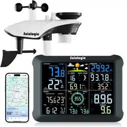
Sainlogic-SA8 Plus
Quick Setup Guide
Product Includes:
- Integrated Outdoor Transmitter
- Display Console
- Rain Collector
- Wind Cups
- Wind Vane
- Mounting Brackets and Accessories
- Instruction Manual
- Power Adapter
Recommended Tools:
- Precision Screwdriver (for small
Phillips screws)
- Compass or GPS (for wind
direction calibration)
- Adjustable Wrench
Step 1:
Locate the battery door on the
bottom of the transmitter, remove the
retaining screws on the back of the
sensor, remove the battery door, insert
3 new AA batteries and close the battery
door.
Step 2:
After installing the batteries, the
Integrated Outdoor Sensor LED will
illuminate for 3 seconds and then blink
every 60 seconds. If it does not flash,
press the reset button.
2
Step 3:
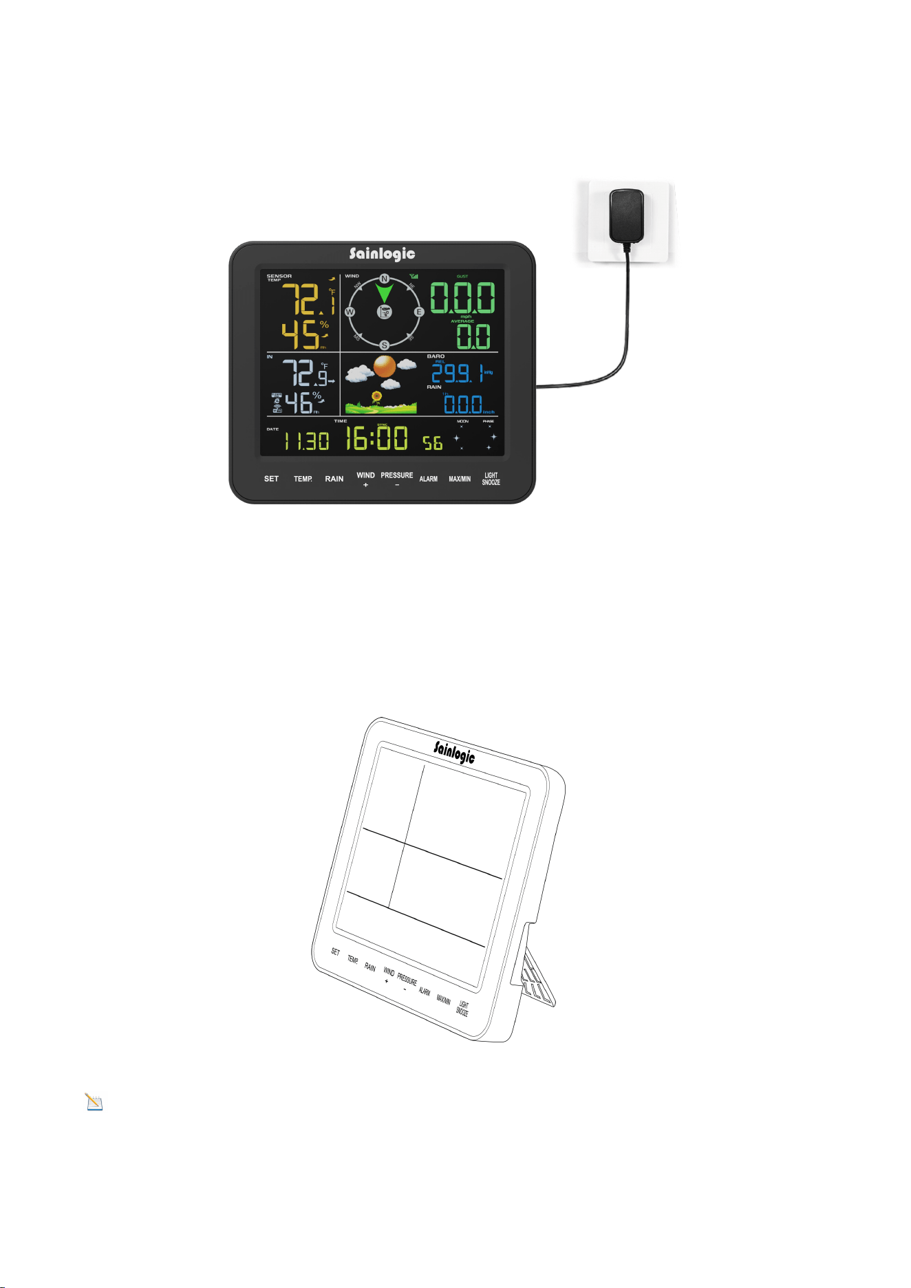
Plug in the display console using the power adapter.
Pairing the indoor and outdoor units:
Press and hold the TEMP button for at least 3 seconds, then press the Reset button
on the outdoor unit once.
We recommend viewing the console at a 20-degree to 30-degree angle from above
for the best display of the screen.
Warning: Please use the adapter to power the device! The battery is for emergen
cy use only!The battery only lasts for a maximum of two hours!
3
Note
:
There are 3 levels of brightness for backlight. When the backlight is on, you can press
the LIGHT SNOOZE key to switch between the 3 levels.
Please review the instructions on the following page.
This guide will show how to connect the display to WiFi, download the
Weatherseed app, and register to log in.
(IOS)
(Android)
Step 4:
Please search "Weatherseed" app in the Google Play
Store or the IOS App Store.
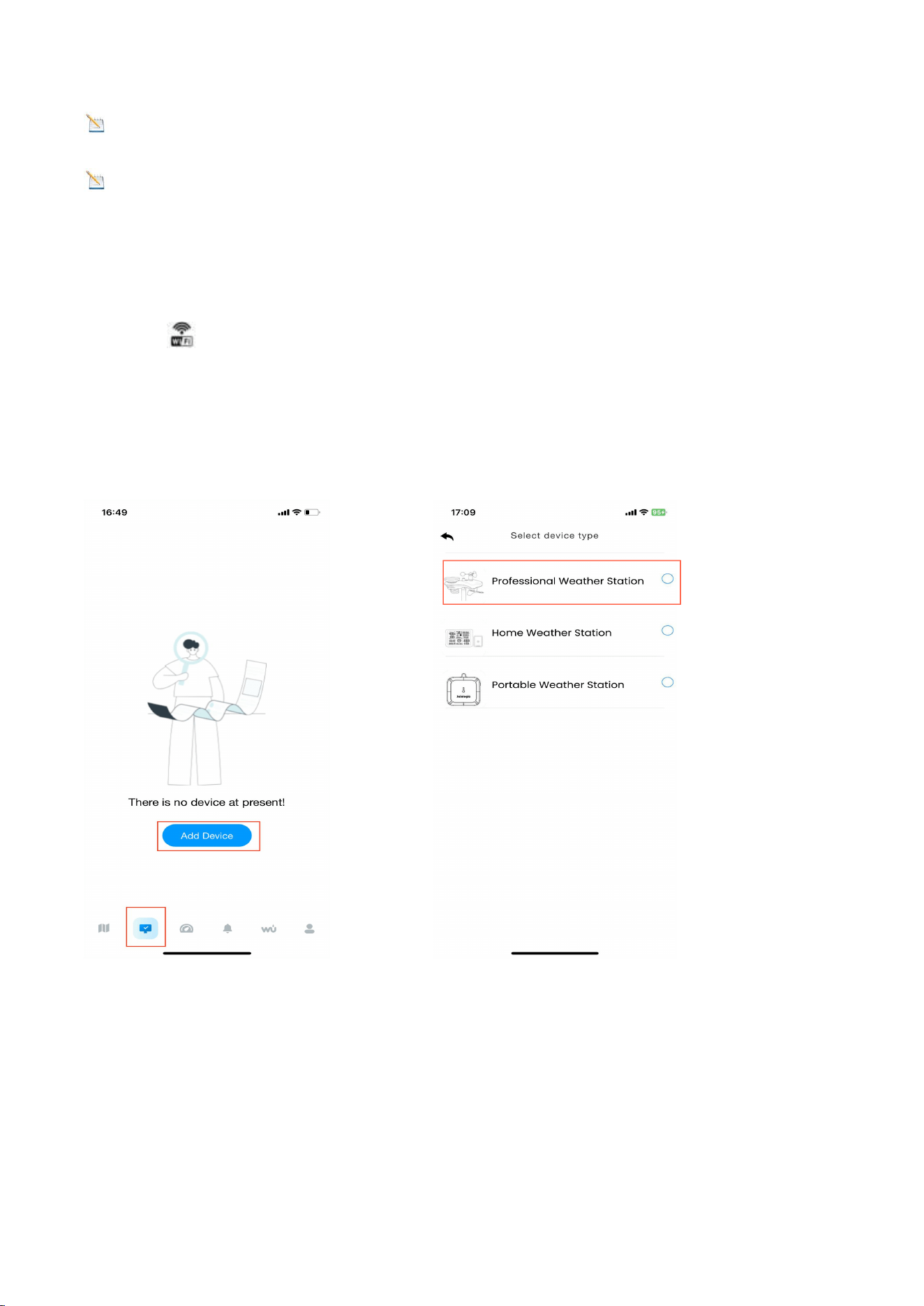
Step 5:
Register with your e-mail address, then log in to your
Weatherseed account:
(1) Enter your preferred account e-mail address.
(2) Send a verification code to the e-mail address,
then enter the code.
(3) Set a password.
(4) Confirm the password (must be consistent with the
set password).
(5) Check the user agreement and proof of age.
(6) Register account.
Step 6: WiFi Connection Steps
Note
:
Please do not select the wrong device type and model. Ifyou
choose the wrong one, the network will not connect successfully.
4
Note
:
The QR code can be found on the back of the Console.
Note
:
If the device is frequently offline, it must be reset. The router should always
be on, it will show offline after no WiFi.
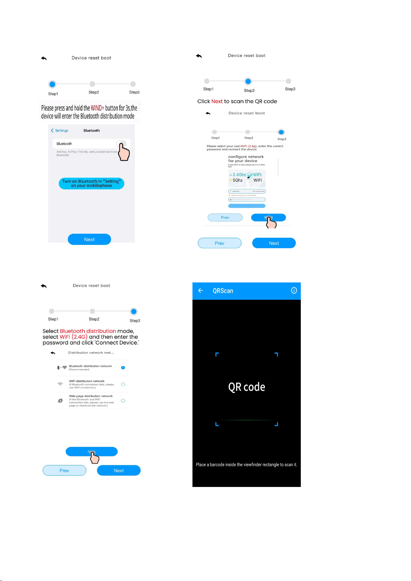
1. Bluetooth Distribution Network Mode(Recommended)
Press and hold the WIND+ key to enter the distribution network mode, The
WiFi icon will flash and the BI icon will be displayed in the date area.
After the display enters the " Bluetooth Distribution Network " mode, please open
the app to start networking:
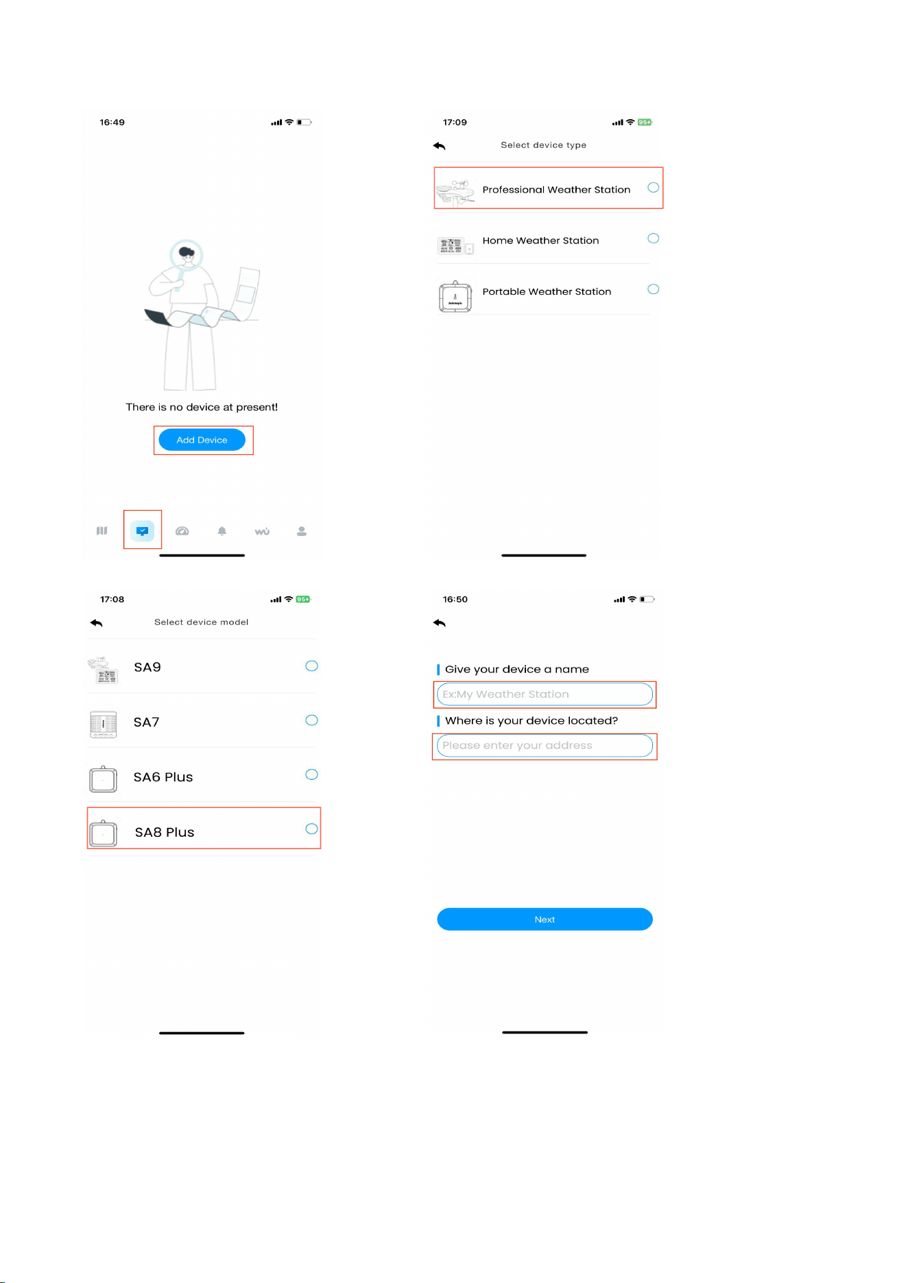
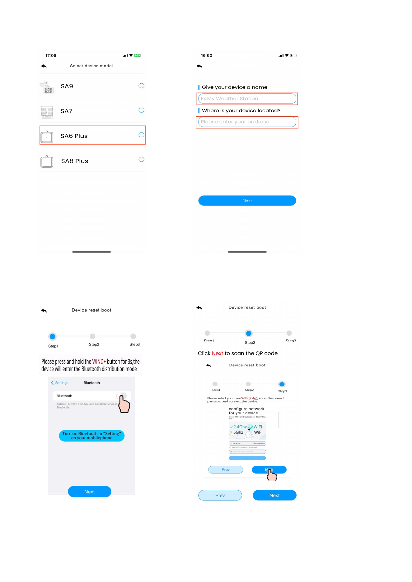
(1) Select product model. Set the name and location.
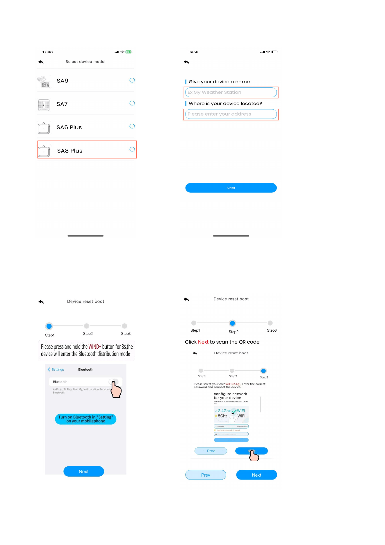
5
(2) Follow steps 1 through 3 for WiFi connectivity. Then, scan the QR code and
select the distribution method.
6
Note
:
The QR code is located on the back of the display.
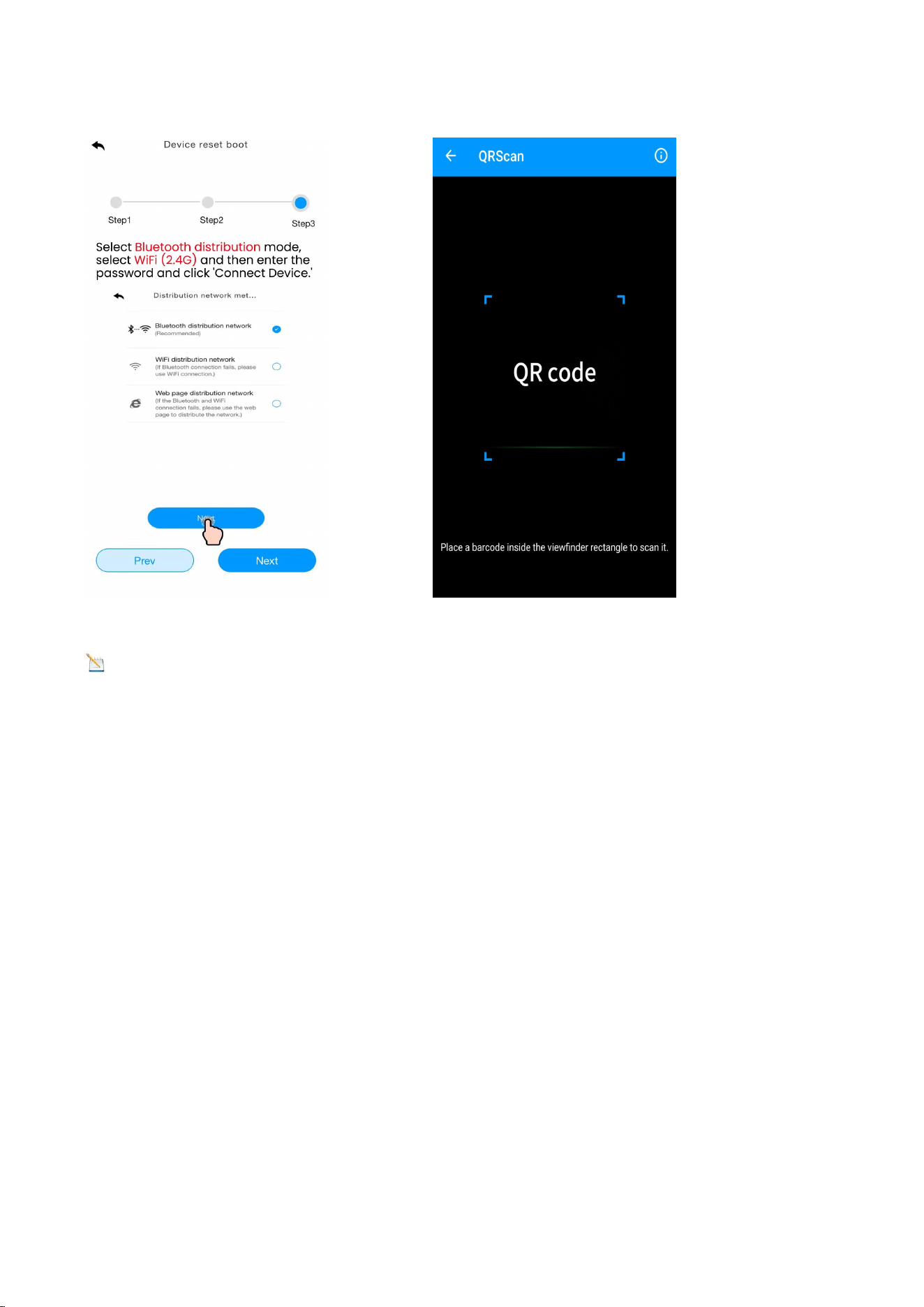
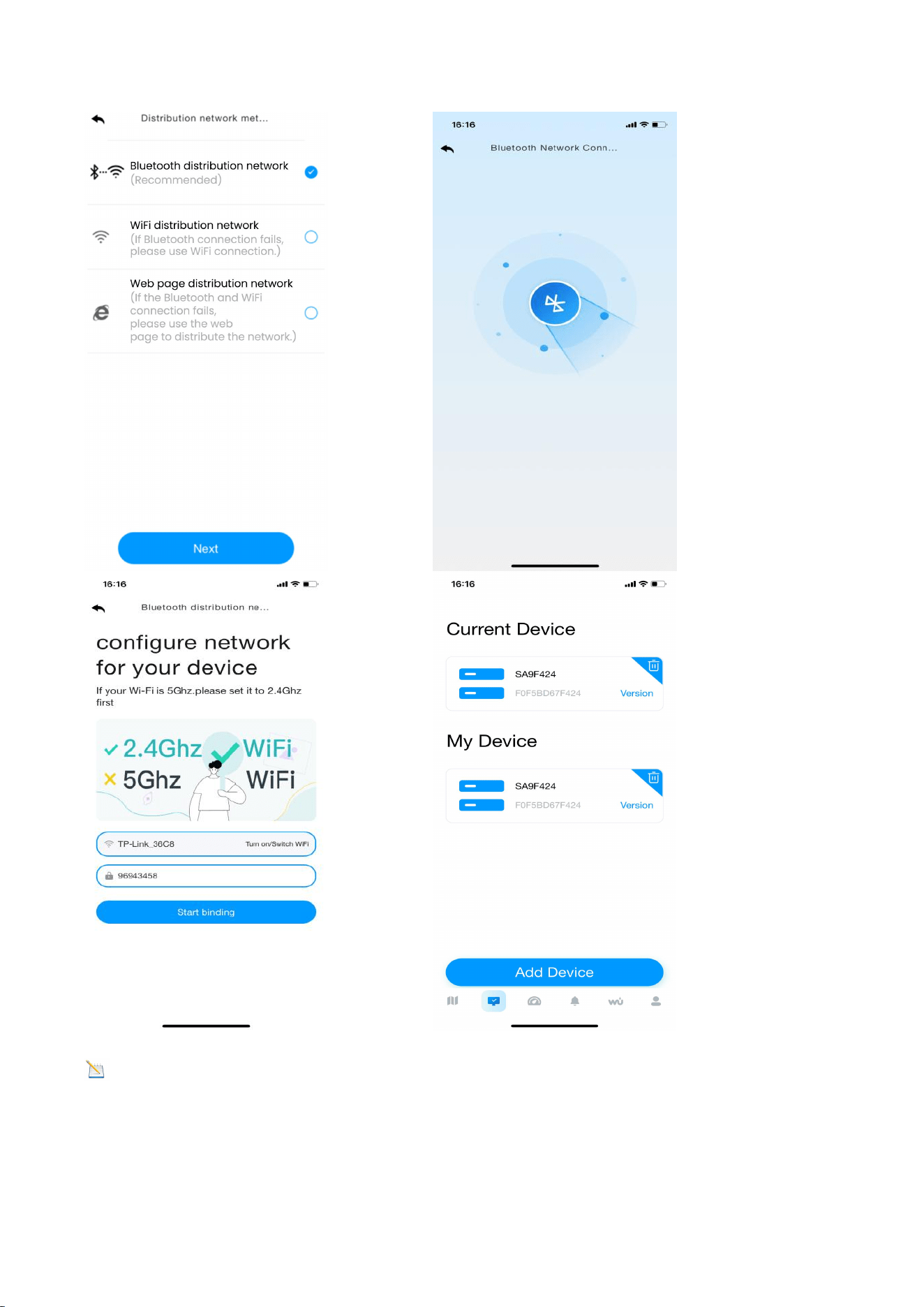
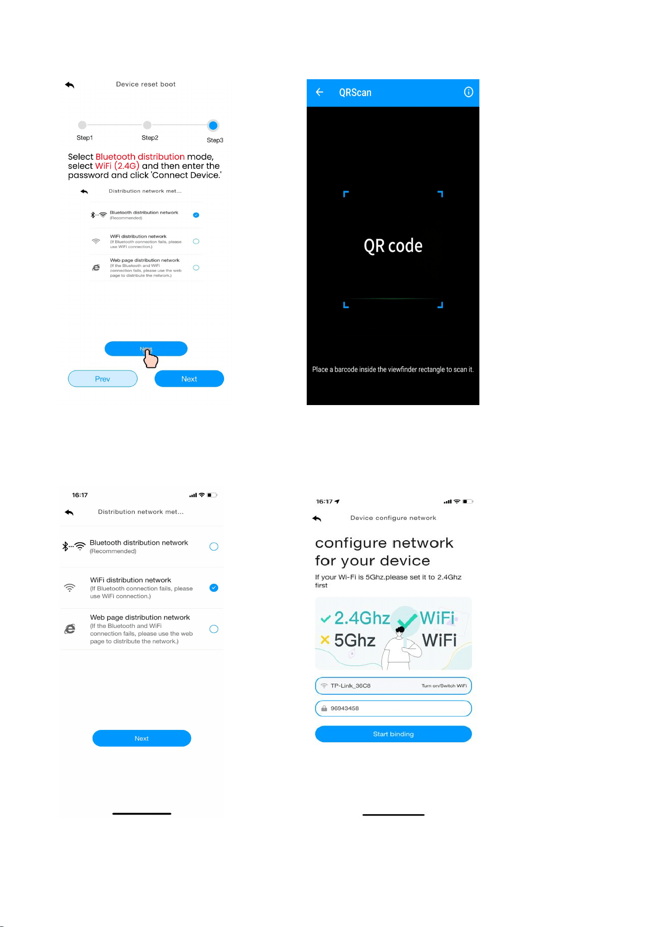
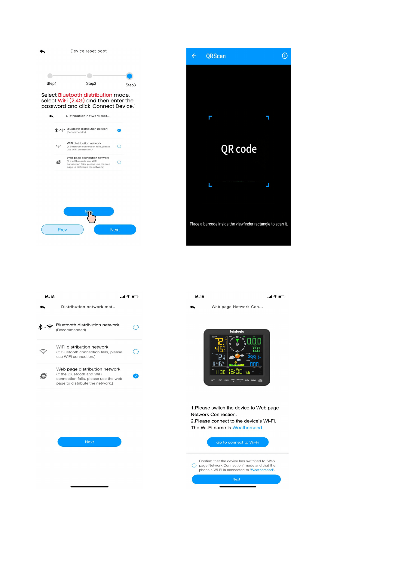
(3) Select “Bluetooth Distribution Network" to automatically search for
Bluetooth signals and pairing. After successful pairing, jump to the WiFi
interface. Please select 2.4ghz WiFi and enter the password.
7
Note : If the connection via Bluetooth Distribution mode fails, please use the
WiFi Distribution Network mode or Web Page Distribution Network mode to set up
the network.
8
2. WiFi Distribution Network Mode
Press and hold the WIND+ key to enter the Distribution Network mode. The
WiFi icon
will
flash. Short press the SET key once, and the SC icon will be
displayed in the date area.
After the display enters the " WiFi Distribution Network " mode, please open the
app to start networking:
(1) Select product model. Set the name and location.
9
(2) Follow steps 1 through 3 for WiFi connectivity, then scan the
QR code and select the distribution method.
10
(3) Choose the “ WiFi Distribution Network“ mode. Select the router WiFi name
(2.4Ghz), then enter the password and click next.
11
3. Web Page Distribution Network Mode
Press and hold the
WIND+
key to enter the Distribution Network mode. The
WiFi icon will flash. Press the SET key briefly twice, then the SC icon will be
converted to the WC icon .
After the display enters the "Web Page Distribution Network" mode, please follow
these steps to connect to the WiFi:
(1)Select product model. Set the name and location.
12
(1) Follow steps 1 through 3 for WiFi connectivity. Scan the QR code, then select
the distribution method.
13
(2) Choose the "Web Page Distribution Network" mode. Click “Go” to connect to
WiFi.
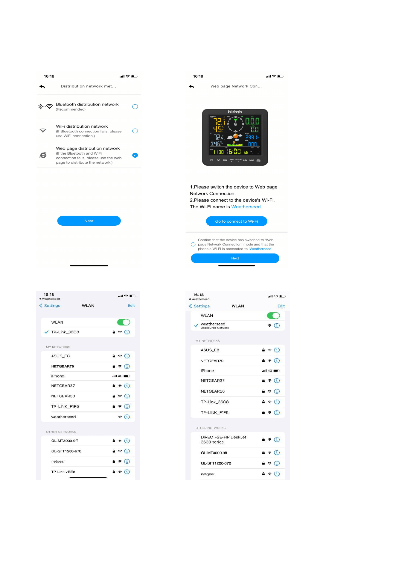
14
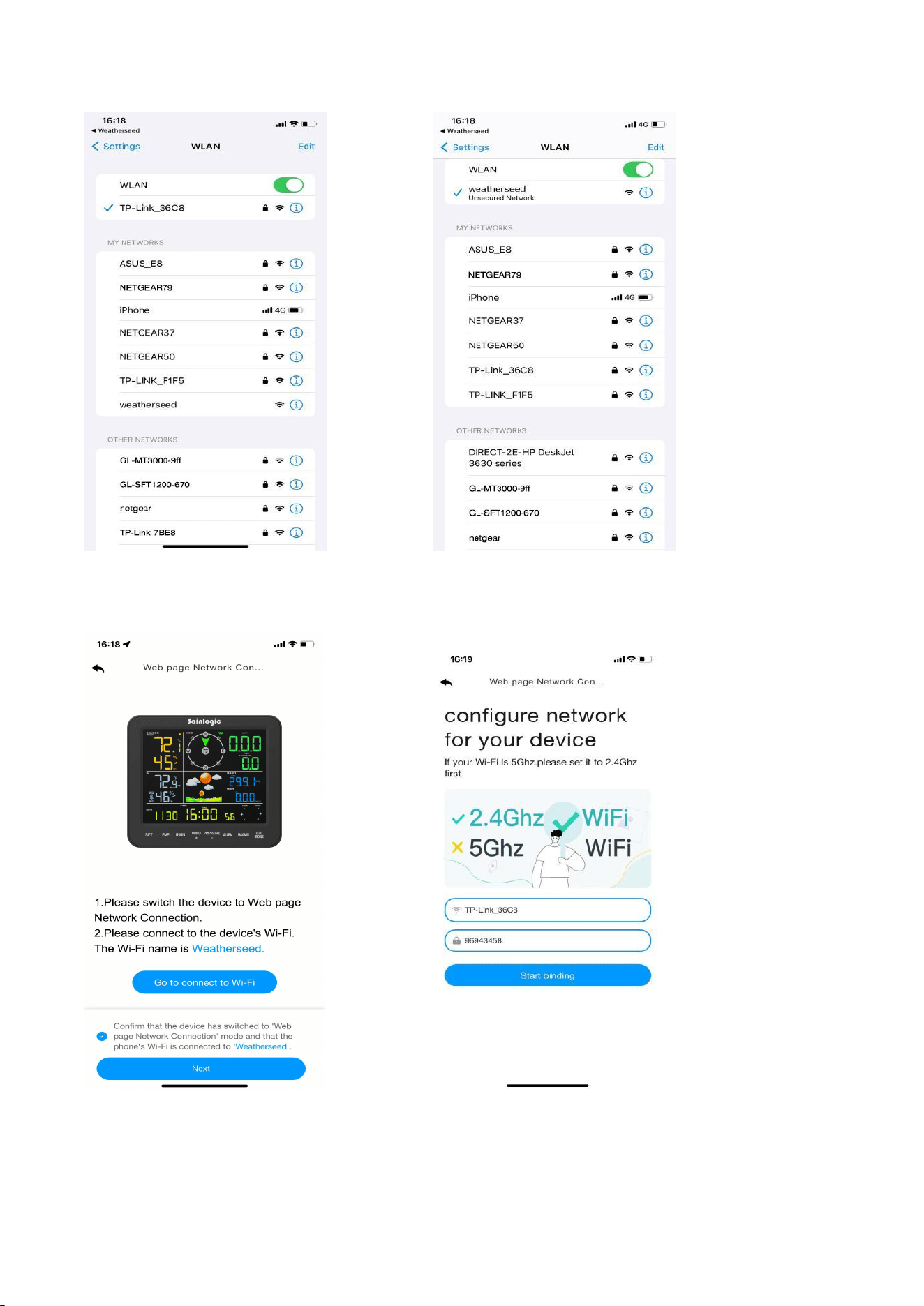
The page will automatically jump to the WiFi list screen. Select the "weatherseed"
WiFi to connect.
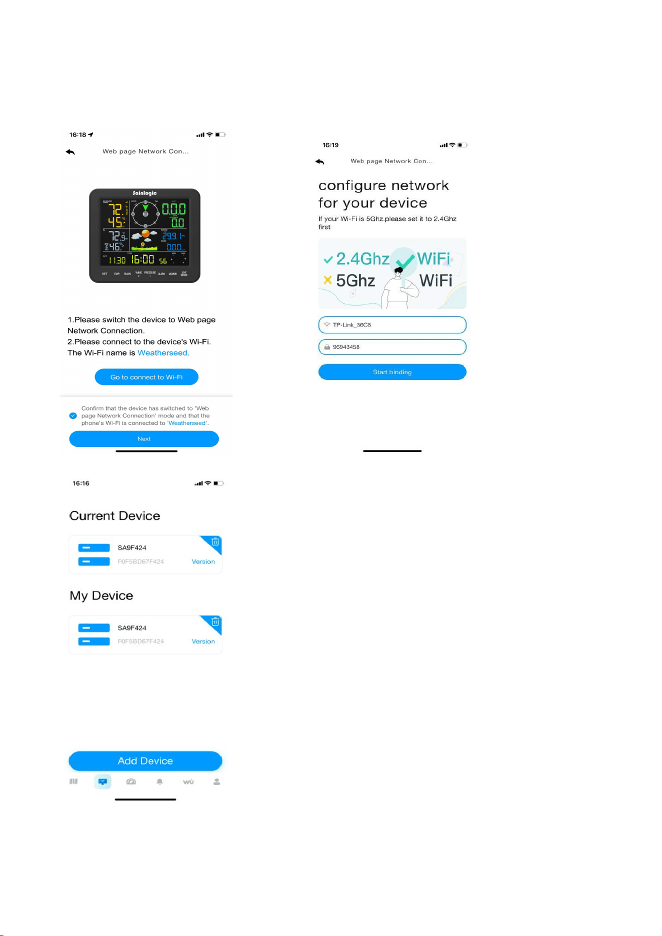
15
(4) Return to the app. Click the confirmation dot and then click "Next".
Please select 2.4ghz WiFi, enter the password, and click "Connect".

16
If you have any questions, please feel free to contact us. You can reach our
Customer Support team via e-mail, phone, or social media.
Website: www.sainlogic.com
Customer Support Phone: +1 (888) 513-9823 (Mon-Fri 10 a.m. - 6 p.m., Eastern
Standard Time)
If you need to register or apply for a warranty, please contact us through Customer
Support.
Customer Support Email:sainlogicwarranty01@gmail.com
Website:https://www.sainlogicwarranty.com/
YouTube:
https://www.youtube.com/@sainlogicbrand
Facebook:
https://www.facebook.com/sainlogicweather
Instagram:
https://www.instagram.com/sainlogic_official/
Twitter:
https://twitter.com/sainlogicbrand
TikTok:
https://www.tiktok.com/@sainlogic.official

1
Sainlogic SA8 Plus Weather Station User Manual
Content
1.Introduction..............................................................................................................3
2.Warning and Cautions .............................................................................................. 3
3.Quick Start Guide ......................................................................................................3
4.Assembly of Sensor Arrays ........................................................................................4
4.1.Parts List ........................................................................................................ 4
4.2.Recommended Tools ..................................................................................... 6
4.3. Remove/Install the Wind Vane ..................................................................... 6
4.4.Remove/Install the Wind Cup ........................................................................ 7
4.5.Remove/ Install the Rain Collector .................................................................7
4.6. Installation of Coil Filters ...............................................................................8
4.7. Install Battery ................................................................................................9
5. Installation of the Sensor Array ..............................................................................11
5.1. Pre-installation Check ................................................................................. 11
5.2. Site Survey .................................................................................................. 11
5.3.Adjusting the Sensor Mounting Direction .................................................... 11
5.3.1. Northern Hemisphere Reference ..................................................... 12
5.3.2. Southern Hemisphere Reference ......................................................13
5.4. Securing the Mounting Pole ........................................................................ 14
5.4.1.Horizontal Mounting And Fixing Sensors ...........................................14
5.4.3. Best Practices for Wireless Communication..................................... 16
6. Install the Display Screen ....................................................................................... 16
7. Start the Display Console ....................................................................................... 18
7.1. Button Operation ........................................................................................ 19
7.2. Display Console ........................................................................................... 20
7.3. Display Restore Factory Settings ................................................................. 21
7.4. Search for Outdoor Sensor Signal ................................................................22
8. Display Connected to WiFi ..................................................................................... 22
8.1. Real-time Network Monitoring................................................................... 22
8.2. App Download ............................................................................................ 22
8.3. App Account Register and Login ..................................................................23
8.3.1. Registering Process .......................................................................... 23
8.3.2. Login Process ....................................................................................24
8.4. MAC Address ...............................................................................................24
8.5. IP Address ................................................................................................... 25
8.6. Connecting Steps ........................................................................................ 25
8.6.1 Bluetooth Distribution Network Mode ..............................................26
8.6.2. WiFi Distribution Network Mode ......................................................30

2
8.6.3. Web page distribution network mode ..............................................34
8.7. Firmware Upgrade...................................................................................... 38
8.8. Sign Up on Wunderground.com.................................................................. 39
9. Display Console Operation.....................................................................................42
9.1. Set Mode .....................................................................................................42
9.2. Time Zone ................................................................................................... 45
9.3. Viewing Max/Min Mode ............................................................................. 46
9.4. Alarm Mode ................................................................................................ 47
9.4.1. Alarm Trigger ....................................................................................48
9.4.2. Viewing High/Low Alarm Values .......................................................48
9.4.3. Setting High/Low Alarms .................................................................. 48
9.5. Calibration Mode ........................................................................................ 54
9.5.1. Calibration Settings .......................................................................... 54
9.5.2. Calibration Ranges ............................................................................57
10. Moon Phase .........................................................................................................61
11. Weather Forecasting ............................................................................................61
11.1. Weather Icon ............................................................................................ 61
11.2. Weather Forecast Instructions and Limitations .........................................62
11.3. Pressure Threshold................................................................................... 62
12. Backlight Operation ............................................................................................. 62
12.1. Connect the Power adapter ...................................................................... 62
12.2. SNOOZE Mode .......................................................................................... 63
12.3.Power Not Connected ................................................................................63
13. Glossary of Terms ................................................................................................ 63
14. Specifications .......................................................................................................65
14.1. Wireless Specifications ..............................................................................65
14.2. Measurement Specifications .....................................................................65
14.3. Power Consumption ..................................................................................66
15. Maintenance ........................................................................................................66
16. Troubleshooting Guide ........................................................................................ 67
17.Disclaimer ............................................................................................................. 71
18. Warranty Information ..........................................................................................72
19. FCC Statement ..................................................................................................... 73
3
1.Introduction
Thank you for purchasing the Sainlogic Professional WiFi Wireless Weather Station.
The following user guide provides detailed instructions on installation, operation, and
troubleshooting. This product is continually evolving and improving, particularly in its
online services and associated applications.
To download the latest manuals and other information, please contact Customer
Support.
Website: www.sainlogic.com
Customer Support Phone: +1 (888) 513-9823 (Mon-Fri 10 a.m. - 6 p.m., Eastern
Standard Time)
2.Warning and Cautions
WARNING: Lightning strikes can be caused by any metal object, including your
weather station mounting pole. Mounting your weather station during a storm is
prohibited.
WARNING: Installing a weather station in an elevated location may result in injury
or death, so perform as many preliminary checks and operations as possible on the
ground and inside a building or house.
WARNING: Install the weather station on a clear, dry day.
3.Quick Start Guide
The following Quick Start Guide provides the necessary steps to install and operate
the weather station.
1
Assembling and Activating the Outdoor Sensor Array
4-5
2
Installing and Activating the Display Console to Connect to the
Outdoor Sensors
6-7
3
Connecting the Weather Station Console to Wi-Fi
8
4
Display Function Setup
9-10
5
Calibration Functions
9.5
6
Troubleshooting
16
4
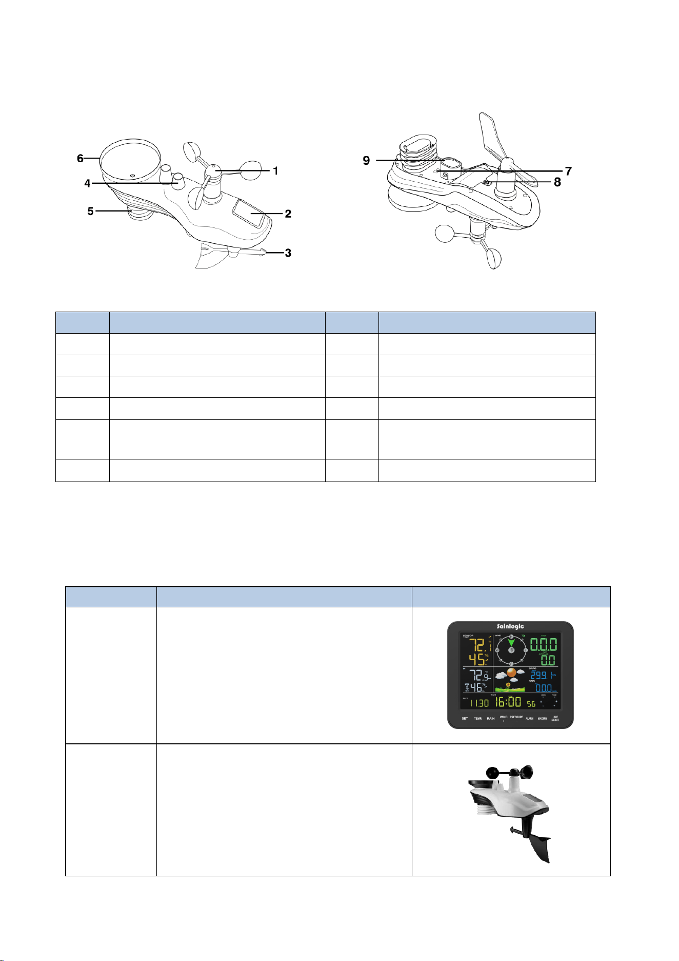
4.Assembly of Sensor Arrays
Figure 1
NO
Description
NO
Description
1
Wind Cup
7
Reset Button/LED Indicator
2
Solar Panel
8
Battery Door
3
Wind Vane
9
Mounting Pole Socket
4
Bubble Level
5
Thermometer-Hygrometer
Sensor
6
Rain Collector
4.1.Parts List
The weather station consists of the following parts.
QTY
Item
image
1
Display Console
Frame Dimensions:
7.5x6.3x1inch
(190x160x25mm)
LCD Dimensions:
5.9x4.5inch
(150x115mm)
1
Integrated Outdoor Transmitter
Dimensions:
12.9x4x9.8inch
(327x101x249mm)
5
1
Foot Mounting (with pole insert)
Dimensions:
4.25x4.1x1.75inch
(107x104x44.5mm)
1
Mounting Bracket Back Plate (pole
mount)
Dimensions:
4x3.25x1inch
(101x82x25mm)
1
Mounting Pole
Dimensions:
12.8x1.3x0.9inch
(325x33x22mm)
2
Pole Mounting Nuts (M3) / Bolts
Ø3)
4
Pole Mounting Nuts (M5) / Bolts
( Ø5)
4
Tapping Screws
1
Manual
1
Power Adapter
1
Precision Screwdriver (for small
Phillips screws)
6
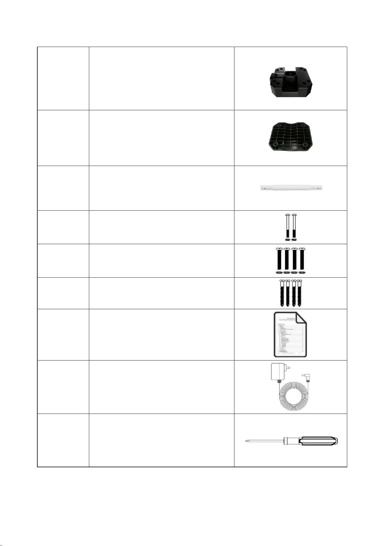
4.2.Recommended Tools
We recommend using the following tools to assist in the installation of the weather
station.
1
Compass or GPS (for wind direction
calibration)
2
Adjustable Wrench
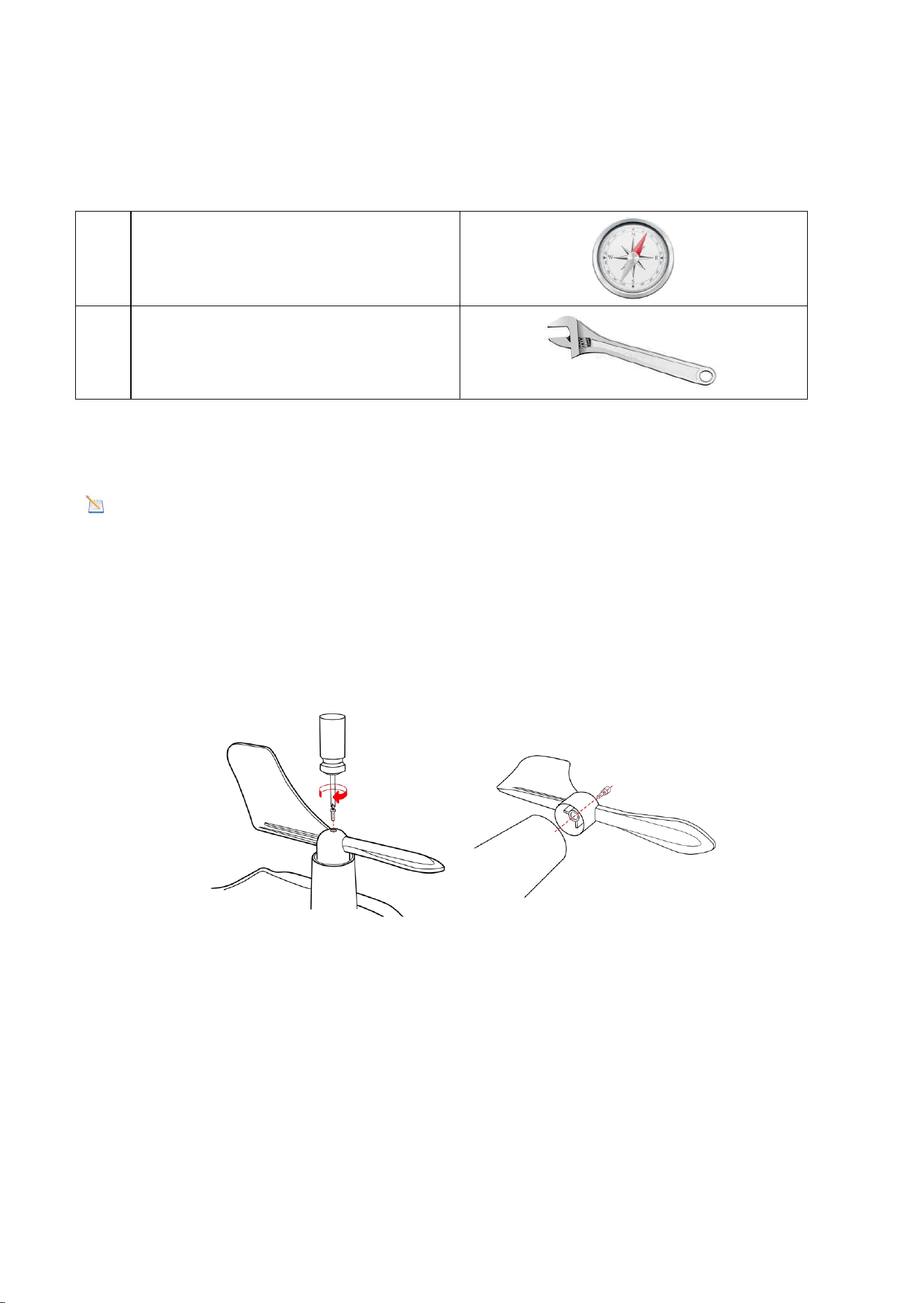
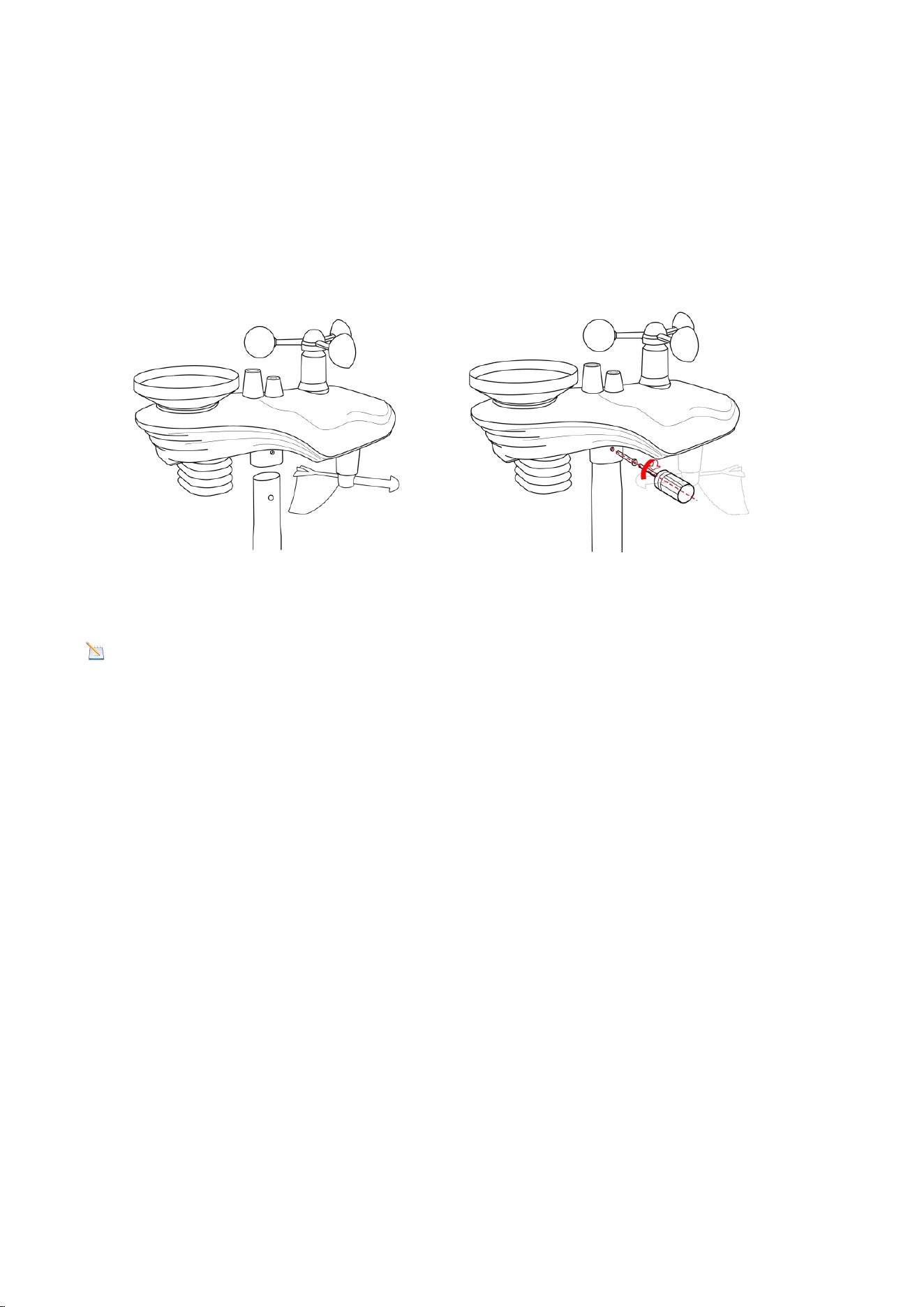
4.3. Remove/Install the Wind Vane
Note: If you need to replace the wind cup and wind vane, follow the steps below.
Remove the Wind Vane: (refer to Figure 2)
(a)Locate the black, waterproof silicone plug in the center of the round cap at the top
of the wind vane and remove it out with a tool.
(b)Use a precision screwdriver to loosen the set screw in the round hole until the
wind vane can be easily removed.
Figure 2
Install the Wind Vane:
(a)Place the round hole at the bottom of the wind vane against the wind vane shaft,
then tighten the fixing screws with a precision screwdriver to ensure the wind vane
can rotate freely.
(b) Insert the black waterproof silicone plug into the round hole at the top of the
wind vane. Ensure it fits snugly into the round hole to achieve a watertight seal.
7
Note: The wind vane axis cannot rotate freely, unlike the wind cup, which was
intentionally designed to do so.
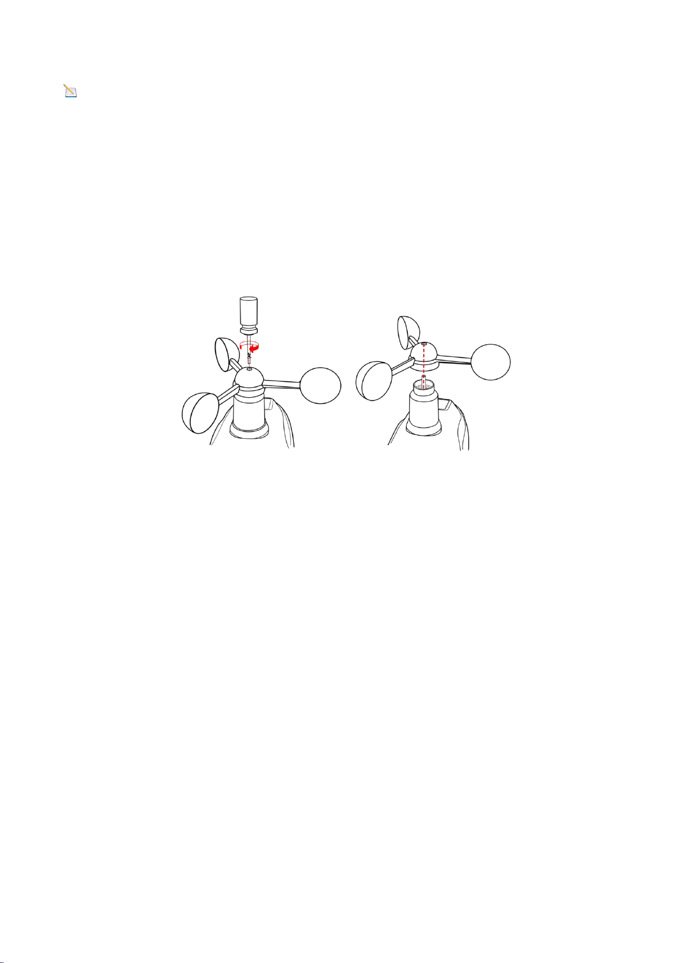
4.4.Remove/Install the Wind Cup
Remove the Wind Cup: (refer to Figure 3)
(a) Locate the black waterproof silicone plug in the center of the round cap at the top
of the wind cup , then remove it with a tool.
(b) Use a precision screwdriver to loosen the set screw in the round hole until the
wind cup can be easily removed.
Figure 3
Install the Wind Cup:
(a) Place the round hole at the bottom of the wind cup against the wind vane axis,
then tighten the fixing screw with a precision screwdriver to ensure that the wind
cup can rotate freely.
(b) Insert the black waterproof silicone plug into the round hole at the top of the
wind cup. Ensure it fits snugly in the hole to achieve a watertight seal.
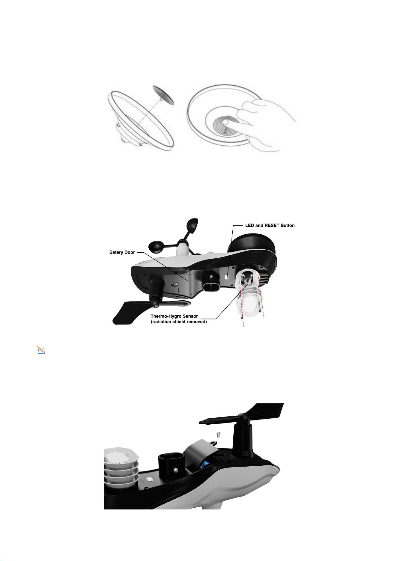
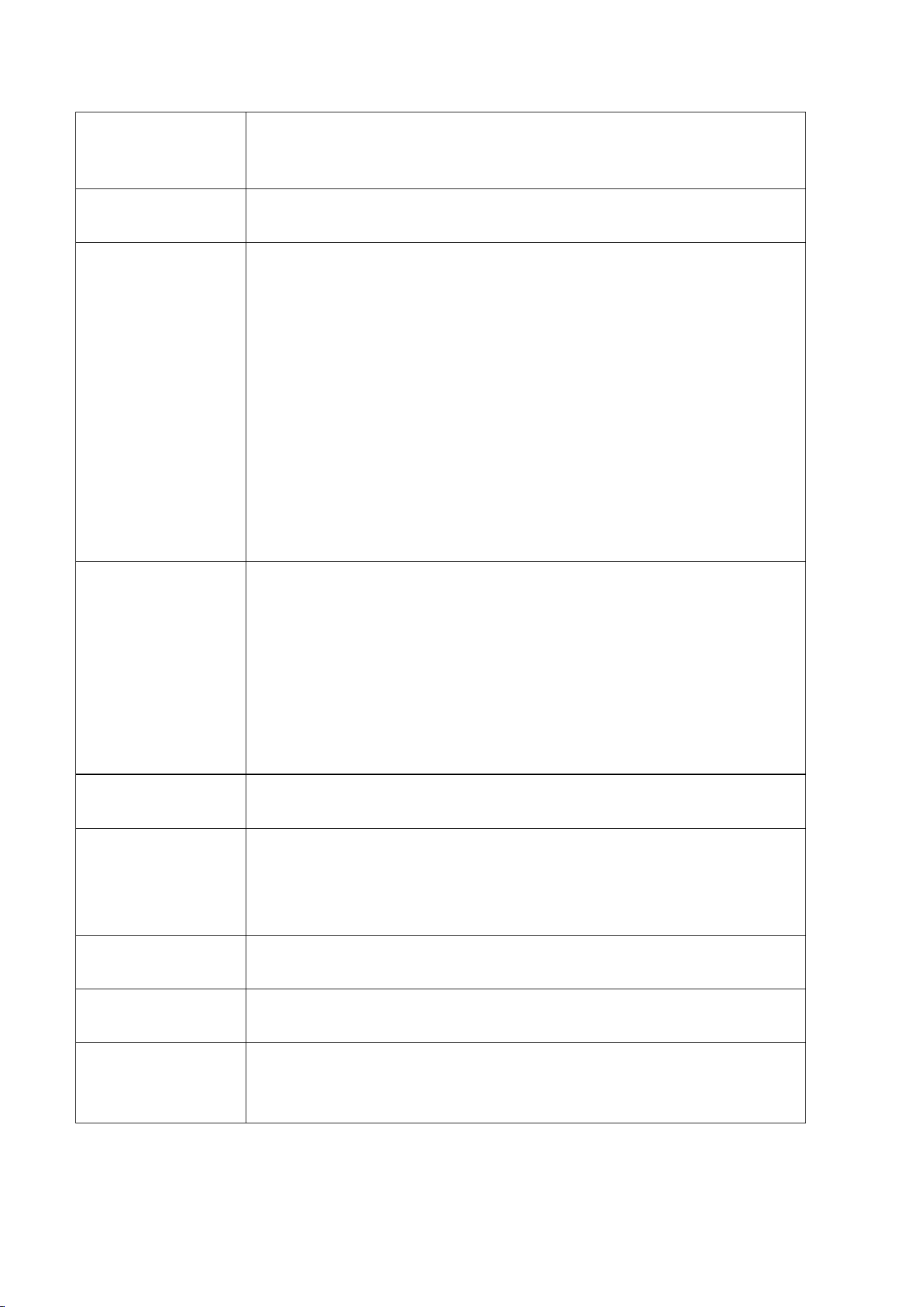
4.5.Remove/ Install the Rain Collector
Remove the Rain Collector:(refer to Figure 4)
(a)Place your hand flat on the top of the rain collector. Grasp the entire collector and
rotate it clockwise.
(b) Remove the rain collector vertically upwards once a click is heard.
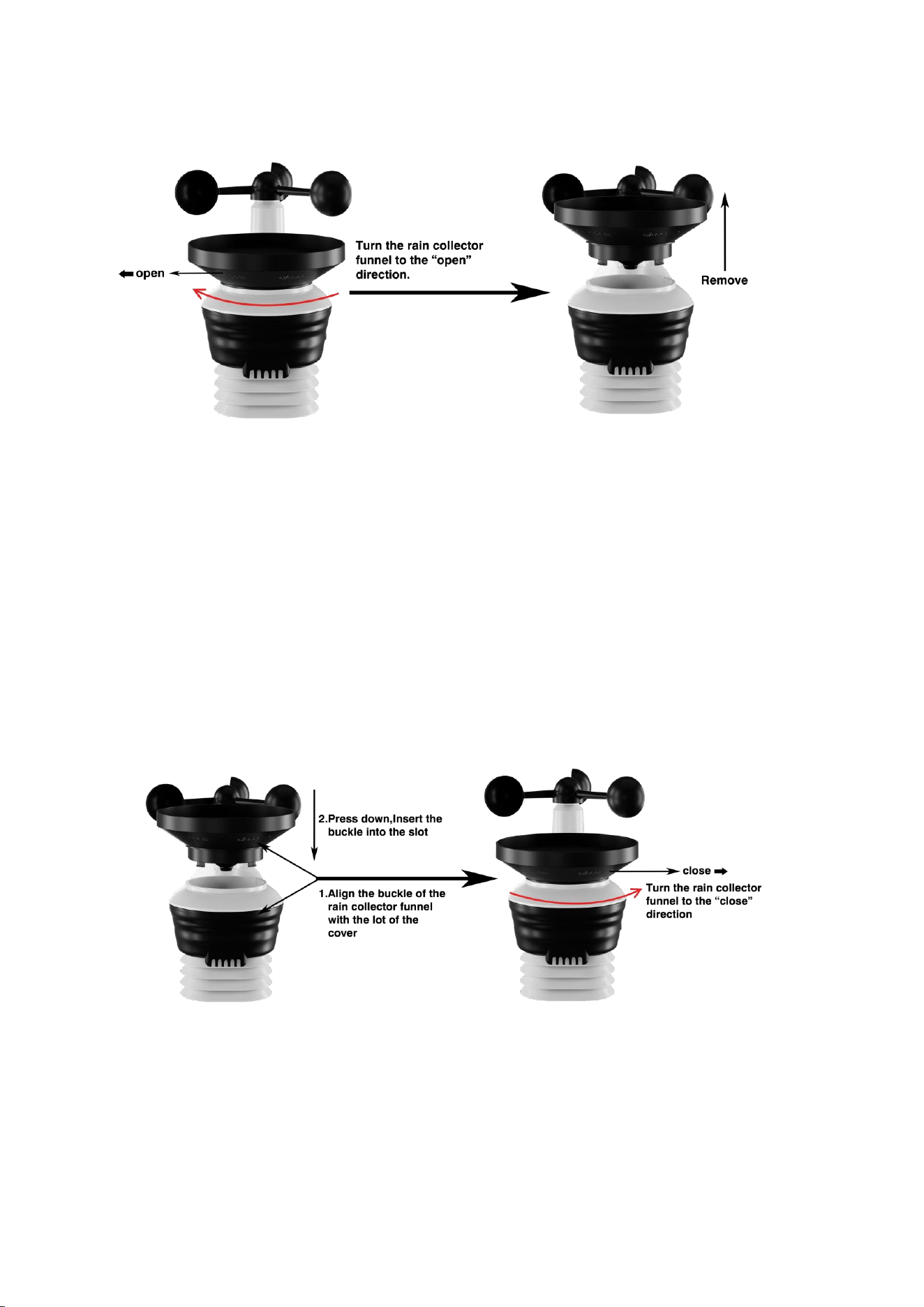
8
Figure 4
Remove the Rain Collector:(refer to Figure 5)
(a) Align the snap on the bottom edge of the rain collector with the snap notch on
the transmitter so that the two fit perfectly. Then, press the rain collector down
vertically.
(b) After placing the rain collector into the groove, rotate it counterclockwise. The
installation will be successful when you hear a click.
Figure 5
4.6. Installation of Coil Filters
(a) Place the coil vertically into the rain collector (hook facing downward) so that the
coil fits snugly against the bottom of the rain collector.
9
(b) Gently press the coil so that it hooks into the hole at the bottom of the rain
collector and locks into place. The tension of the spring will keep the filter tightly
fitted to the rain collector.
Figure 6
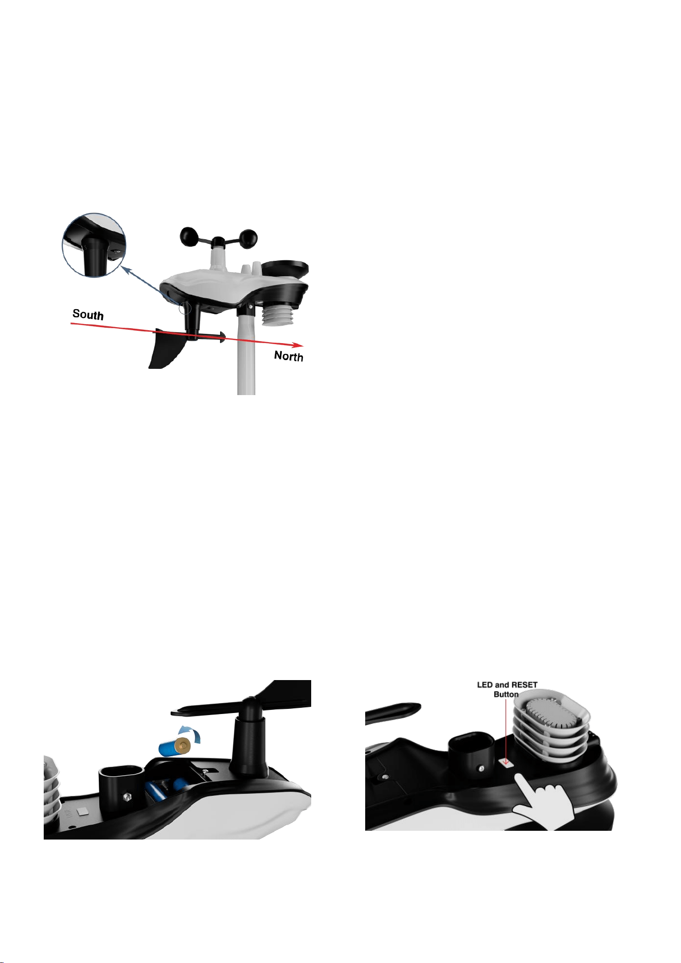
4.7. Install Battery
Locate the battery door at the bottom of the transmitter, as shown in Figure 7.
Figure 7
Note: Do not install the batteries backwards. You can permanently damage the
outdoor sensors.
Remove the battery door on the back of the sensor by removing the set screw, as
show in Figure 8.
10
Figure 8
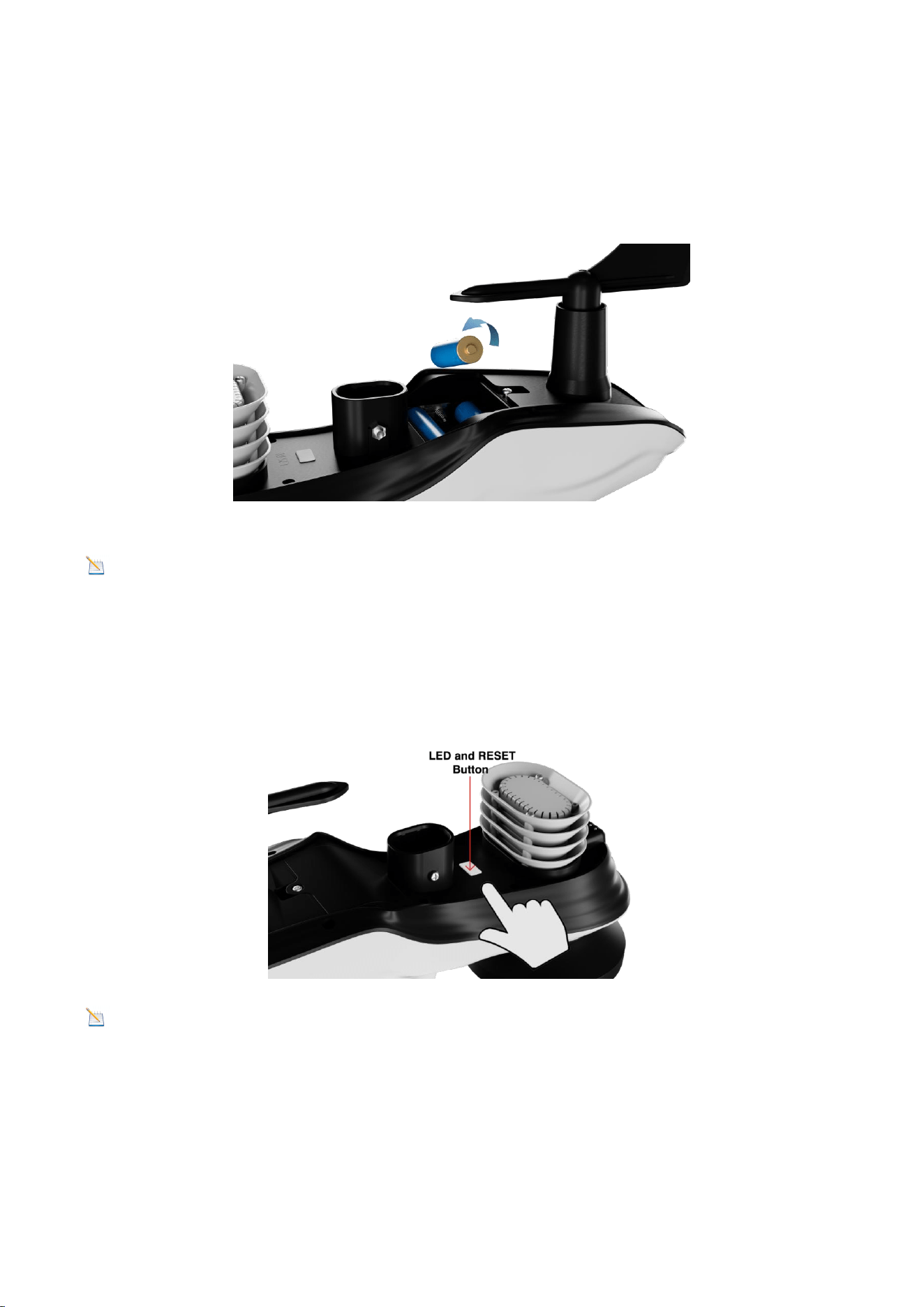
Insert 3 new AA batteries and close the battery door as shown. Before closing the
battery door and tightening the set screws, make sure the washers (around the
inside perimeter of the battery door) are properly secured in their tracks.
Figure 9
Note: We recommend installing AA lithium batteries for the Outdoor Sensor in
cold weather environments.
Once the battery is installed, the Integrated Outdoor Sensor LED indicator will
illuminate for 3 seconds and then blink every 60 seconds. The sensor is transmitting
data each time it blinks.
Figure 10
NOTE: If the sensor LED does not flash after inserting the batteries, press the reset
button located at the bottom of the sensor, as shown in Figure 10.

11
5. Installation of the Sensor Array
5.1. Pre-installation Check
Before installing the weather station in a permanent location, we recommend
running it at a temporary, easily accessible location for one week. This allows you to
check all functions in advance, ensure they are operating correctly, and familiarize
yourself with the weather station and calibration procedures.
5.2. Site Survey
Before installing the weather station, consider the following points during the site
survey:
1. The rain gauge must be cleaned every 3 months and the battery should be
replaced every 3 months.
2. Avoid heat radiation transfer from buildings and structures. Generally, the sensor
array should be installed at least 5 feet (1.5 meters) away from any buildings,
structures, ground, or roofs.
3. Avoid influencing wind speed and rainfall measurements. The installation distance
of the sensor array should be at least four times the height of the highest obstacle.
For example, if a building is 20 feet (6 meters) high and the installation pole is 6 feet
(2 meters) high, the installation distance should be 4 x (20 - 6) = 56 feet (17 meters).
If the weather station is installed near tall buildings, wind speed and rainfall
measurements may be inaccurate.
4. Radio signal range. Assuming no interference from buildings, trees, vehicles, high-
voltage lines, and other obstructions, the radio communication distance between the
display console and the transmitter can reach up to 330 feet (100 meters). In most
cases, due to interference from buildings and walls, most wireless applications can
only reach up to 100 feet (30 meters). Radio signals cannot penetrate metal buildings.
5. In the worst-case scenario, radio interference from personal computers, radios, or
televisions can completely cut off radio communication. Therefore, consider this
when selecting a display console or determining the installation location.
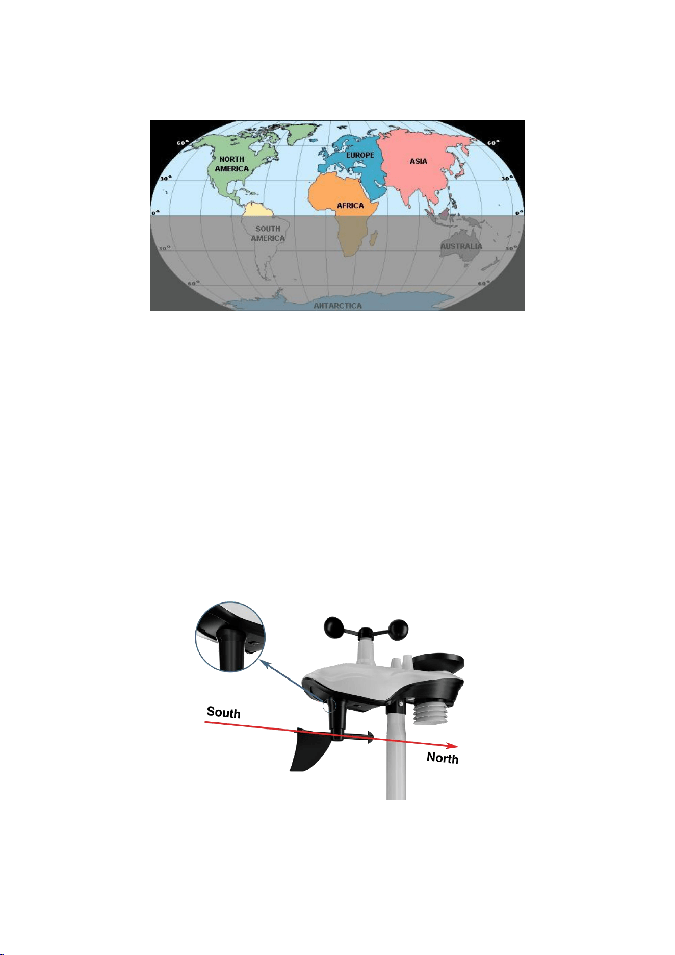
5.3.Adjusting the Sensor Mounting Direction
This professional weather station is suitable for use in both the Northern and
Southern Hemispheres. To ensure the accuracy of the wind direction display, please
secure the direction of the integrated outdoor sensor before installation.
Note: Wind direction is indicated by the letters N, E, S, and W. (N is north, E is
east, S is south, W is west)
12
Northern Hemisphere
Southern Hemisphere
Figure 11
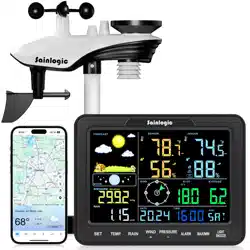
5.3.1. Northern Hemisphere Reference
The body of the outdoor sensor is embossed with the four cardinal directions: N, E, S,
W, which are applicable only in the Northern Hemisphere.
Step 1: As shown in the diagram, there is an "S" indicator on the wind vane
representing south.
Using a compass, check the direction and adjust the orientation of the entire sensor
to ensure the "S" mark on the sensor aligns with the south.
Figure 12
13
Step 2: On the display console, set the location region to the Northern Hemisphere
(NOR will appear in the time zone).
(For detailed steps on setting the location region, see Step 18 in section 9.1).
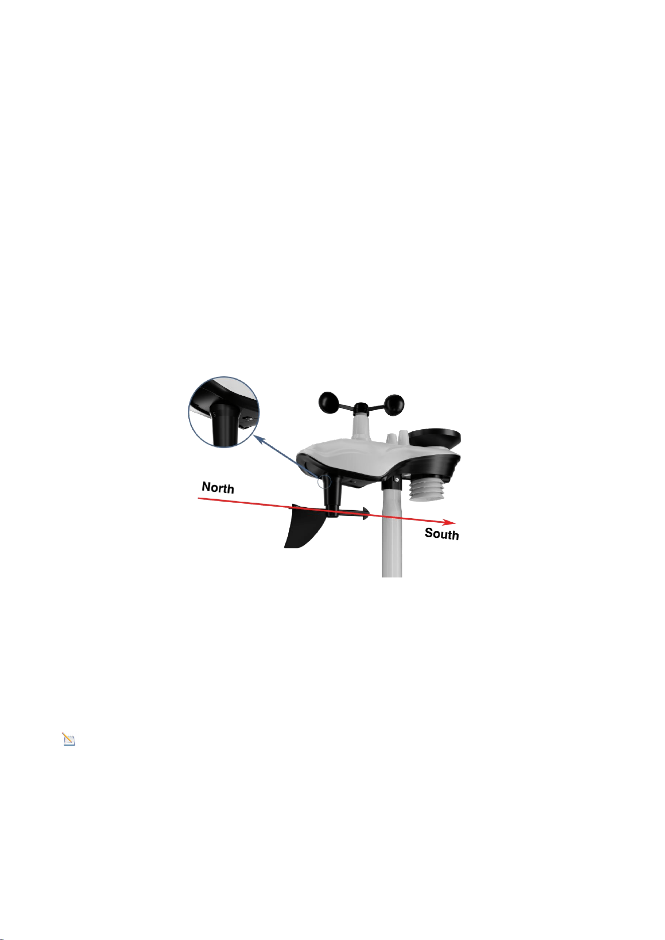
5.3.2. Southern Hemisphere Reference
For installing the integrated outdoor sensor in the Southern Hemisphere, disregard
the four directions (N, E, S, W) marked on the sensor body. When installing, adjust
the orientation of the entire outdoor sensor to ensure the solar panel faces north
(and is positioned to receive maximum sunlight), as shown in the diagram.
Step 1: Install the Integrated Outdoor Sensor
Ensure the solar panel is positioned to face north.
Figure 13
Step 2: Set the Location Region on the Display Console
Set the location region to the Southern Hemisphere (SOU will appear in the time
zone).
(For detailed steps on setting the location region, please refer to Step 18 in section
9.1).
Note: The location region (NOR or SOU) on the display console and the sensor
direction must be adjusted according to your actual location.
If the integrated outdoor sensor is not positioned correctly during installation, it
will result in permanent wind direction errors.
14
5.4. Securing the Mounting Pole
Observe the bubble level next to the rain gauge to ensure the bubble is stable within
the circle, keeping the sensor array completely level. If the sensor array is not level,
the rain gauge will not measure accurately.
Figure 14
NOTE: If the bubble level cannot be read due to mounting limitations, a
horizontal line or level can be placed across the top of the rain gauge for easier
viewing.
5.4.1.Horizontal Mounting And Fixing Sensors
Fasten the integrated outdoor sensor to the mounting bar bracket with two
mounting bolts (Ø4)/nuts (M3). Then, tighten the mounting bar to your existing
mounting bar using four bolts (Ø5) and nuts (M5), or secure it to a flat surface with
four self-tapping screws, as shown. (Figure 15 )
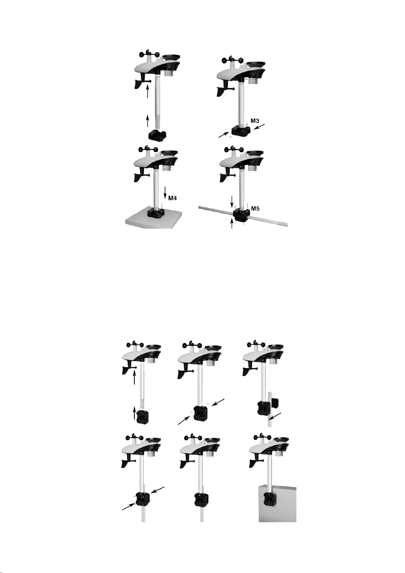
15
Figure 15
5.4.2. Vertical Mounting And Fixing Sensors
Fasten the integrated outdoor sensor to the mounting bar bracket with two
mounting bolts (Ø4)/nuts (M3). Then, tighten the mounting bar to your existing
mounting bar with four bolts (Ø5) and nuts (M5), or secure it to a flat surface with
four self-tapping screws, as shown. (Figure 16)
16
Figure 16
5.4.3. Best Practices for Wireless Communication
Wireless communication is susceptible to interference, distance, walls, and metal
barriers. We recommend the following best practices for trouble-free wireless
communication.
1. Electro-Magnetic Interference (EMI): Keep the console several feet away from
computer monitors and TVs.
2. Radio Frequency Interference (RFI): If you have other 433 MHz devices and
communication is intermittent, try turning off these other devices for
troubleshooting purposes. You may need to relocate the transmitters or receivers to
avoid intermittent communication.
3. Line of Sight Rating: This device is rated at 300 feet line of sight (no interference,
barriers, or walls), but typically you will get 100 feet maximum. [This is under most
real-world installations, which include passing through barriers or walls.]
4. Metal Barriers: Radio frequency will not pass through metal barriers, such as
aluminum siding.
If you have metal siding, align the remote and console through a window to get a
clear line of sight.
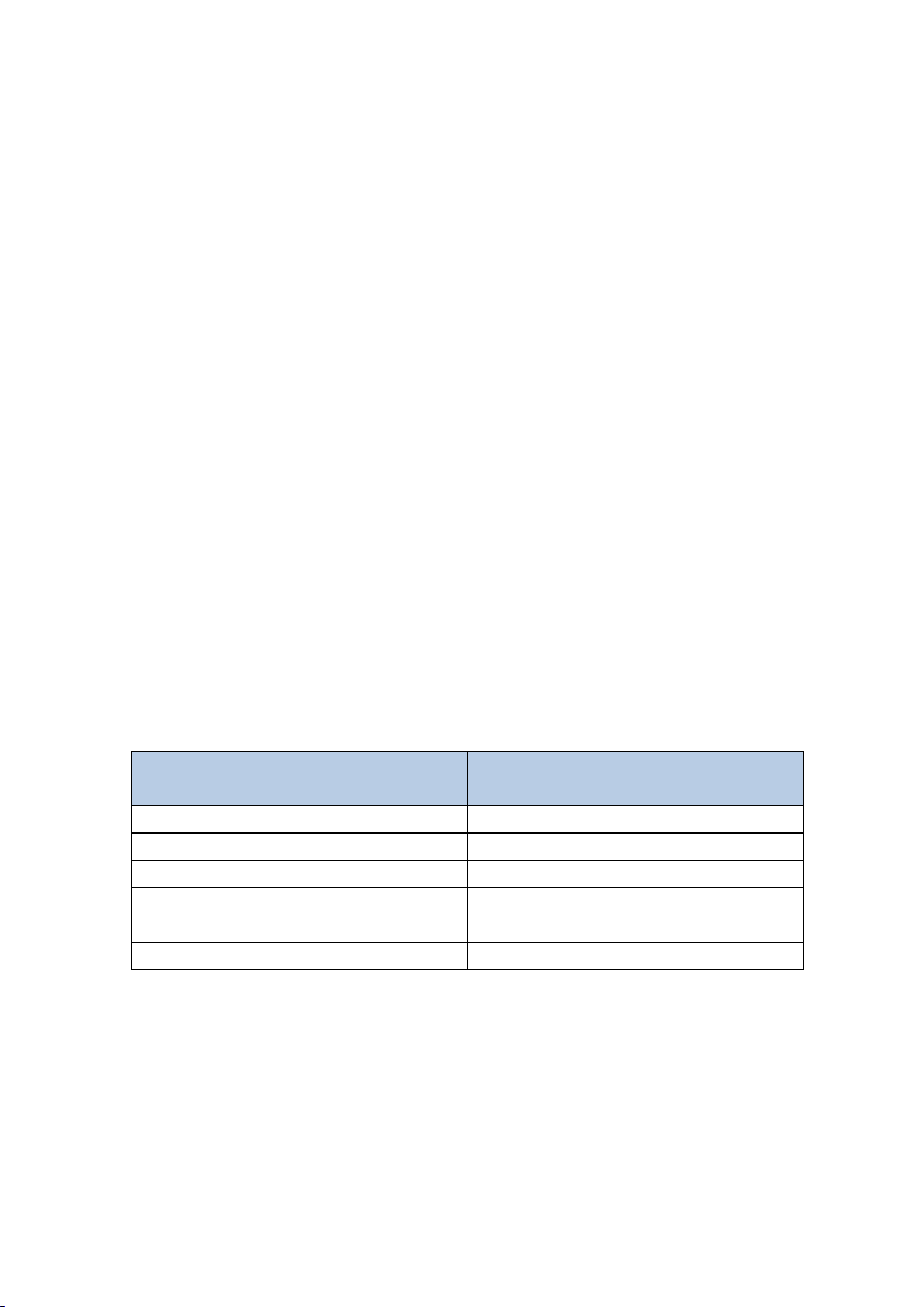
The following is a table of reception loss, versus the transmission medium. Each “wall”
or obstruction decreases the transmission range by the factor shown below:
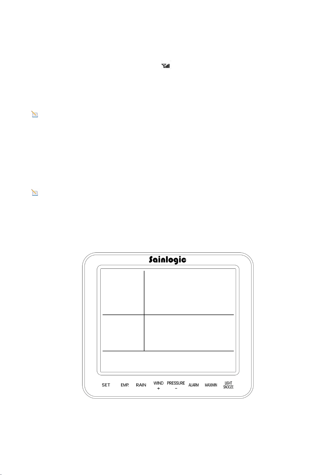
6. Install the Display Screen
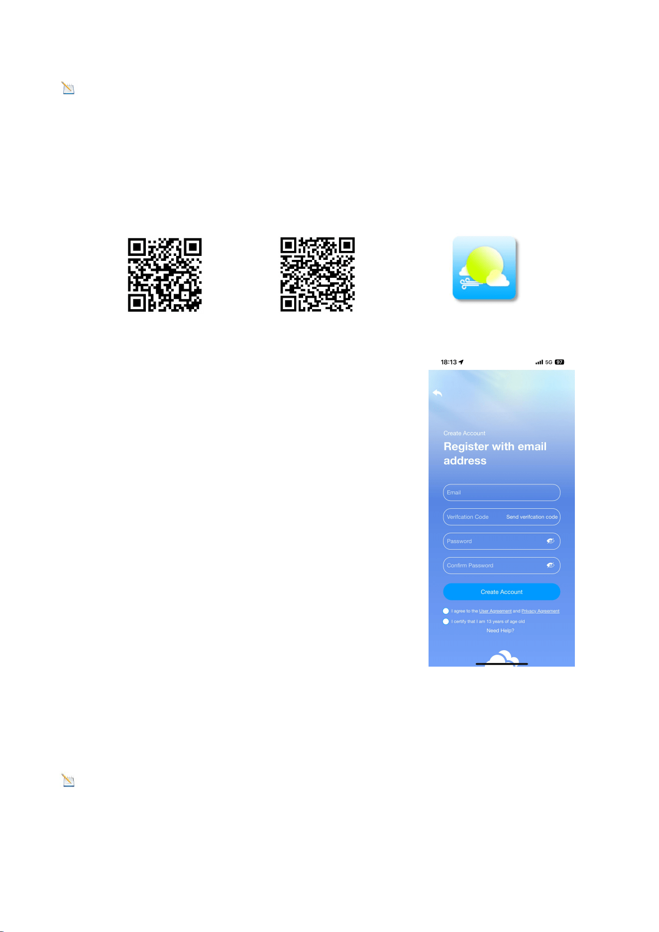
The front and back diagram of the console is shown in the figure below.
Medium
Radio Frequency (RF) signal
strength reduction
Glass (untreated)
5-15%
Plastic
10-15%
Wood
10-40%
Brick
10-40%
Concrete
40-80%
Metal
90-100%
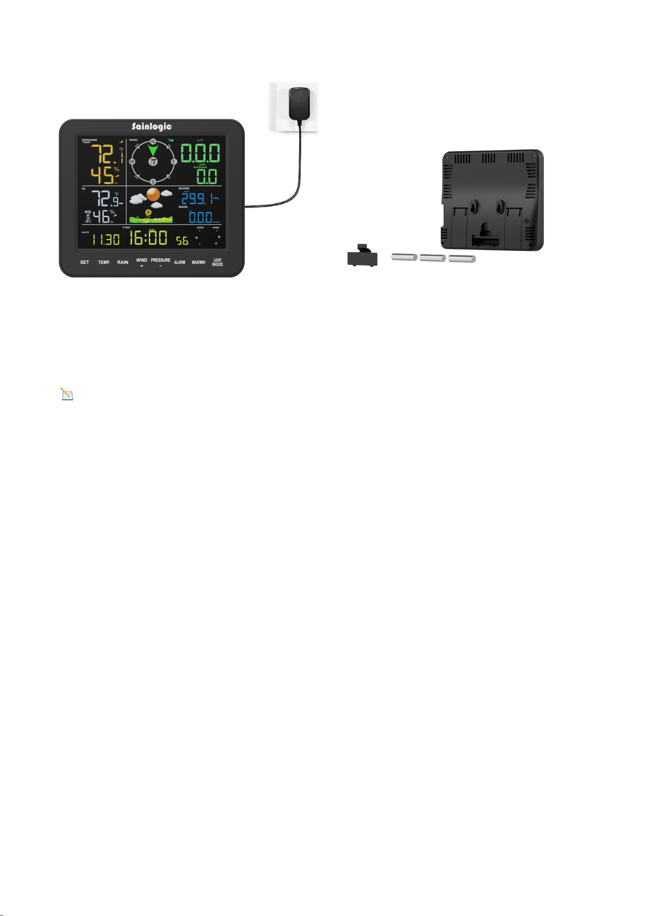
17
Figure 17
(1) Plug in the display console with the power adapter.
Warning: Please use the adapter to power the device! The battery is for emergen
cy use only!The battery only lasts for a maximum of two hours!
(2) Install the display console batteries.
Remove the battery door on the back of the display (Figure 17) and install three AAA
(alkaline or lithium) batteries. The display will beep and all layouts on the display will
light up for a few seconds as a verification that the display is working properly.
(3) Use the Display Stand.
The folding tabletop stand on the back of the display console is positioned at roughly
45 degrees to the display (Figure 18). We recommend viewing the console from a 20-
degree to 30-degree angle from above for the best display of the screen.
18
Figure 18
7. Start the Display Console
As shown in the figure, once the display console is powered up, it will display all
layouts of the screen for three seconds. Then, it will automatically scan all nearby
integrated outdoor sensors. The indoor data will be updated immediately, and the
outdoor sensor data will be updated within a few minutes.
Figure 19
19
In Search Mode, the Remote Search icon will blink continuously and will not stop
until all measurements have been received, then it will remain permanently lit. The
console will automatically switch to normal mode where all other settings can be
performed.
Note: Do not touch any buttons on the display until all remote sensors have
reported data on the display or the display console will terminate the connection to
the remote sensors.
When the integrated outdoor sensor is connected, the measured values (outdoor
temperature, humidity, wind speed, wind direction, gusts and average wind, and
rainfall) will be displayed on the display console.
Note: Ensure that the distance between the weather station's sensor and the
display console is between 10 feet (3 meters) and 100 feet (30 meters). If the
weather station sensor is too close or too far away, it may not receive the proper
signal.
7.1. Button Operation
Figure 20
20
There are the following 8 keys on the console (from left to right), which are used to
set the display functions by click, long press.
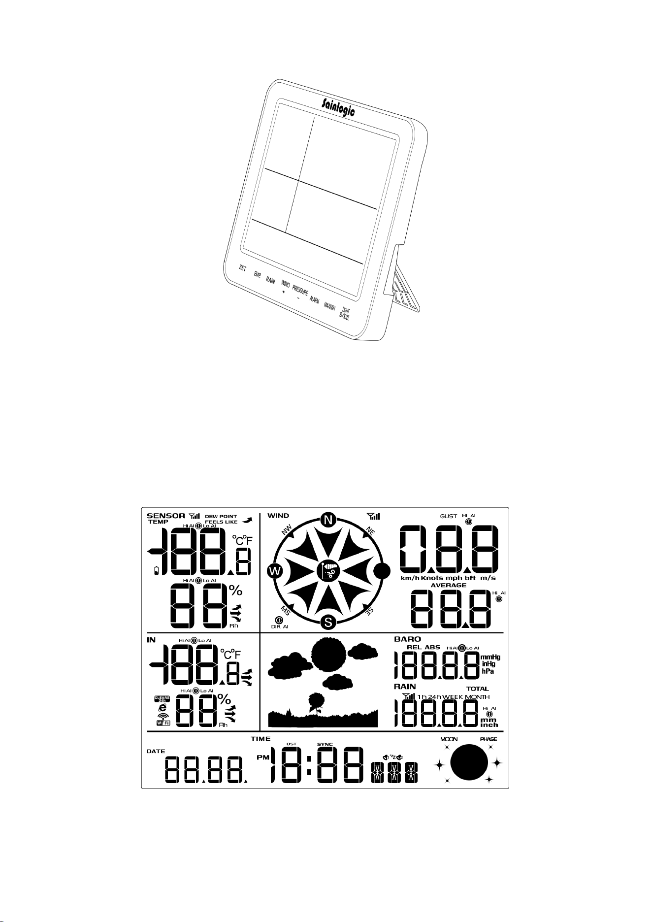
7.2. Display Console
The following figure shows the layout of all the data on the display.
Key
Description
SET
1. Click to switch the displayed time (year, month, day, second,
week)
2. Long press to enter the settings interface and click to switch to
the next item
TEMP
1. Long press to pair the indoor and outdoor units
2. Click to switch (dew point, feels like, temp)
RAIN
1. Long press to clear rainfall
2. Click to switch rainfall display (1h, 24h, week, month, total)
WIND +
1. Long press to enter the network distribution, SET to switch to
network distribution mode
2. Increase the value when setting parameters
PRESSURE -
1. Long press to view IP address
2. Click to switch to display pressure (REL/ABS)
3. Reduce the value when setting parameters
ALARM
1. Long press to set alarm information
2. Click to enter the high alarm information interface, low alarm
interface
3. Set alarm parameters, long press the alarm button to clear the
data
MAX/MIN
1. Click to enter the maximum/minimum value interface
2. Long press to display mac address
LIGHT
SNOOZE
1. In normal mode, click to adjust the backlight brightness
2. In setting mode, click to return to normal mode
3. Long press to turn on or off the constant light mode
21
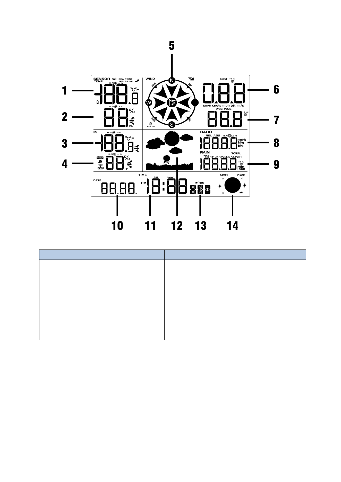
Figure 21
7.3. Display Restore Factory Settings
To reset the console to factory default settings (including weather server and display
settings), follow these steps:
1. Remove the battery and disconnect the power adapter to power off the console.
2. Connect the power adapter and power on.
3. When all layouts are displayed on the screen, press and hold the WIND + key at the
same time, which will prompt two beeps until the console boot process is completed.
4. Replace the battery.
No
Description
No
Description
1
Outdoor Temperature
8
Barometric Pressure
2
Outdoor Humidity
9
Rainfall
3
Indoor Temperature
10
Date
4
Indoor Humidity
11
Time
5
Wind Direction
12
Weather Icon
6
Wind Gust
13
Week/Second
7
Average Wind Speed
14
Moon Phase
22
7.4. Search for Outdoor Sensor Signal
If the outdoor sensor data is not displayed on the screen, you can press and hold the
TEMP button for three seconds. At the same time, press the reset button on the
outdoor unit again.
At this point, the display will re-receive the signal from the outdoor sensor, and the
search icon will start flashing. Once the signal is reacquired, all data will be
displayed, the remote search icon will remain lit, and the screen will show the
current values.
Note: Pressing the LIGHT SNOOZE button briefly can exit the signal search mode;
if the search times out after 60 seconds, it will also exit the signal search mode.
8. Display Connected to WiFi
8.1. Real-time Network Monitoring
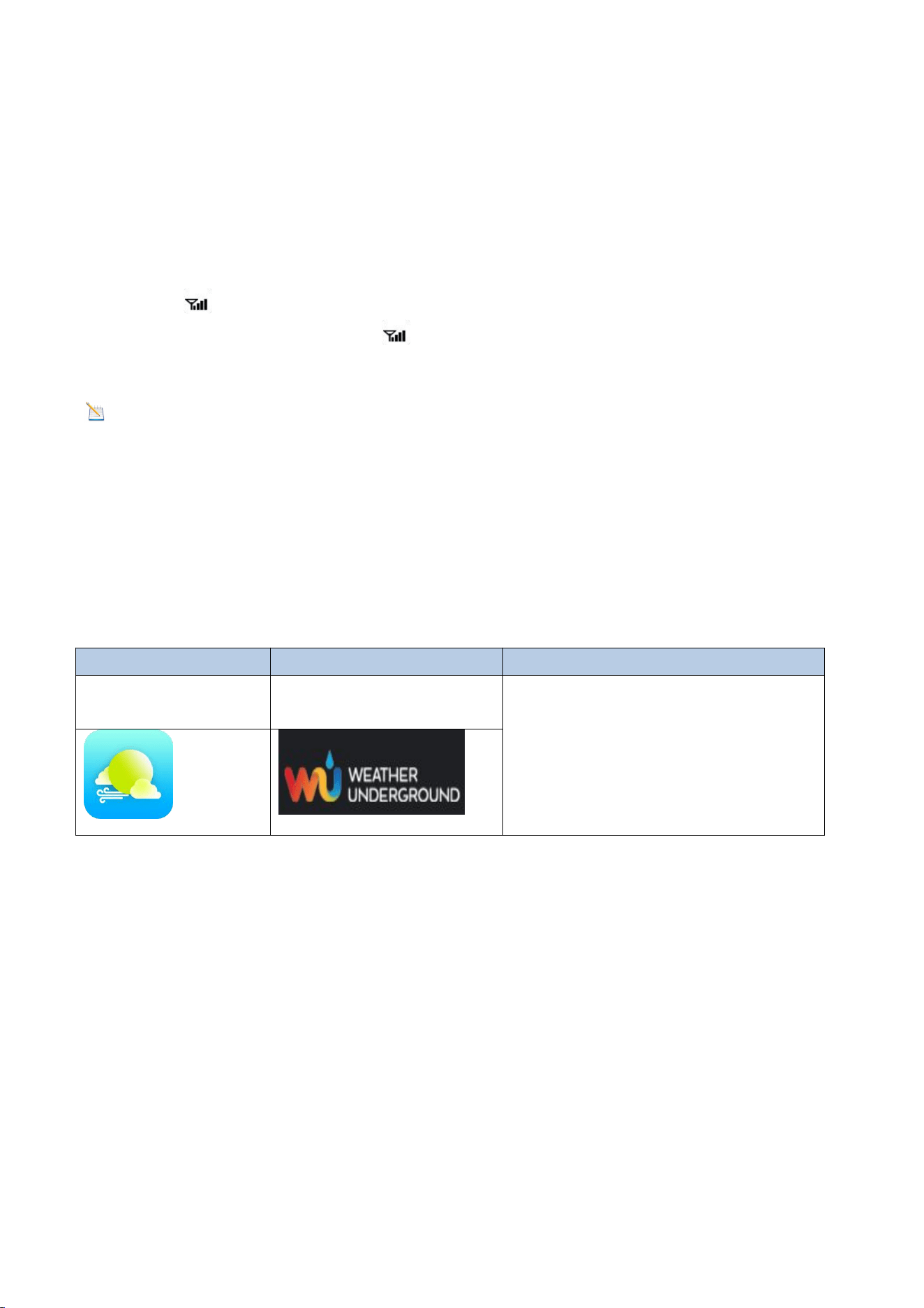
The weather station can upload data to the following two platforms:
Application Services
Website
Description
Weatherseed App
Wunderground.com
Our weather stations feature the
most user-friendly design to
monitor data across different
platforms. Use our animated
expandable modules to quickly
view the details you want.
*Weather station uses the WiFi connection to send data to the Internet.
* Please DO NOT fill in any credit card information on Weather Underground website.
If a pop-up window appears when you open the Weather Underground website,
please be careful and not to click it!
8.2. App Download
Please search for "Weatherseed " in the Google Play or IOS App Store.
After downloading, you can follow the steps to connect the weather station to WiFi
and then view the data on the app.
23
8.3. App Account Register and Login
After successfully downloading the Weatherseed app, please open the app. The first
time you open the app, the login or registration screen will appear. If you don't have
an account, you need to register to create an account to log in with. If you have
already registered a Weatherseed account, you can log in directly without registering
again.
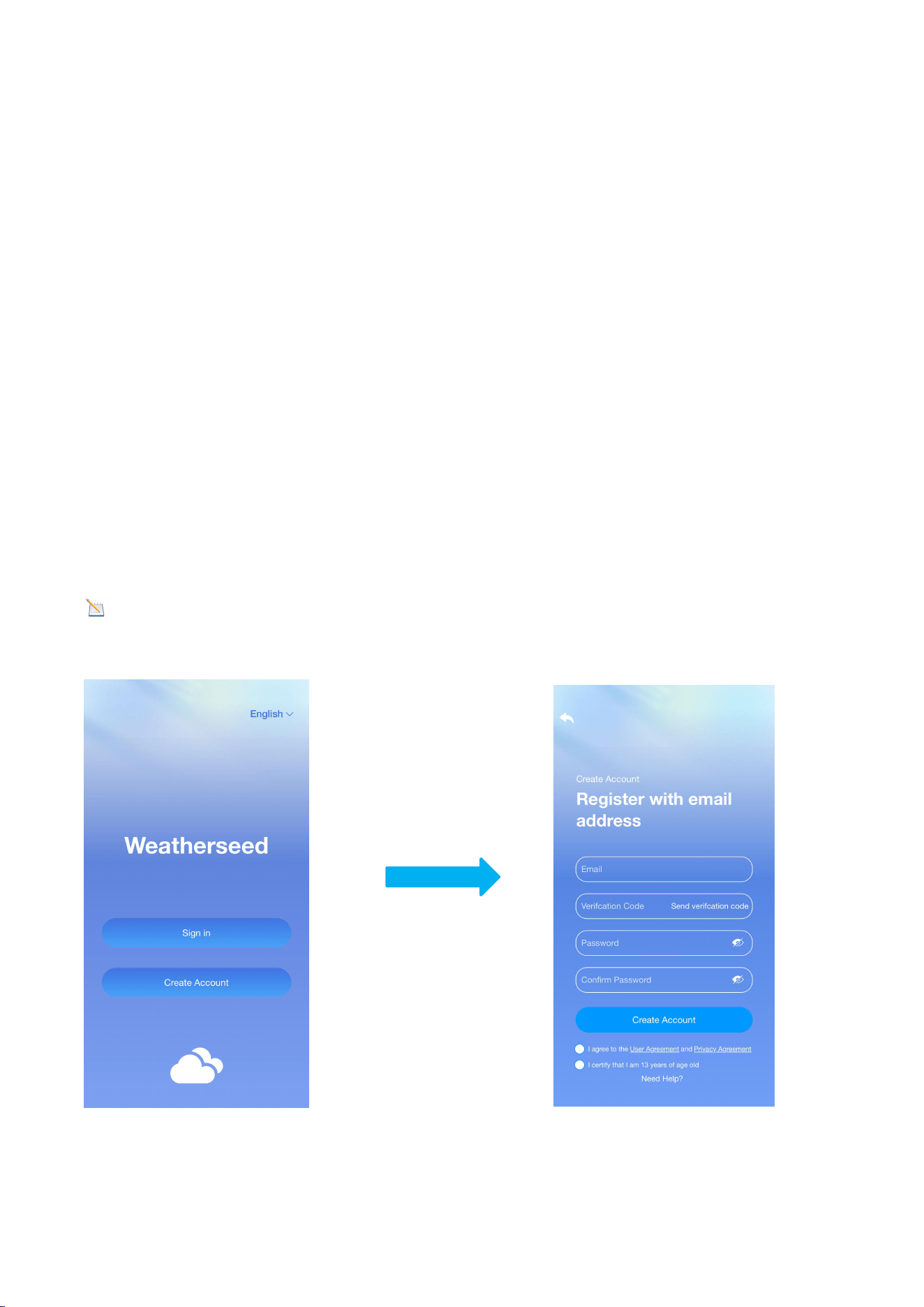
8.3.1. Registering Process
Follow the steps below to register your Weatherseed account:
(1) Fill in your e-mail address.
(2) Send the verification code to the e-mail address.
(3) Go to the e-mail address to check the verification code and enter it.
(4) Set a password.
(5) Confirm the password (must be consistent with the set password).
(6) Check the user agreement and proof of age.
(7) Register an account.
Note: Your account will be automatically logged into the app directly after the
registration is completed.
24
8.3.2. Login Process
Follow the steps and picture instructions below to log in to your Weatherseed
account:
(1) Enter your registered Weatherseed account (e-mail address).
(2) Enter the password you have created.
(3) Check the User Privacy Agreement.
(4) Log in to your account.
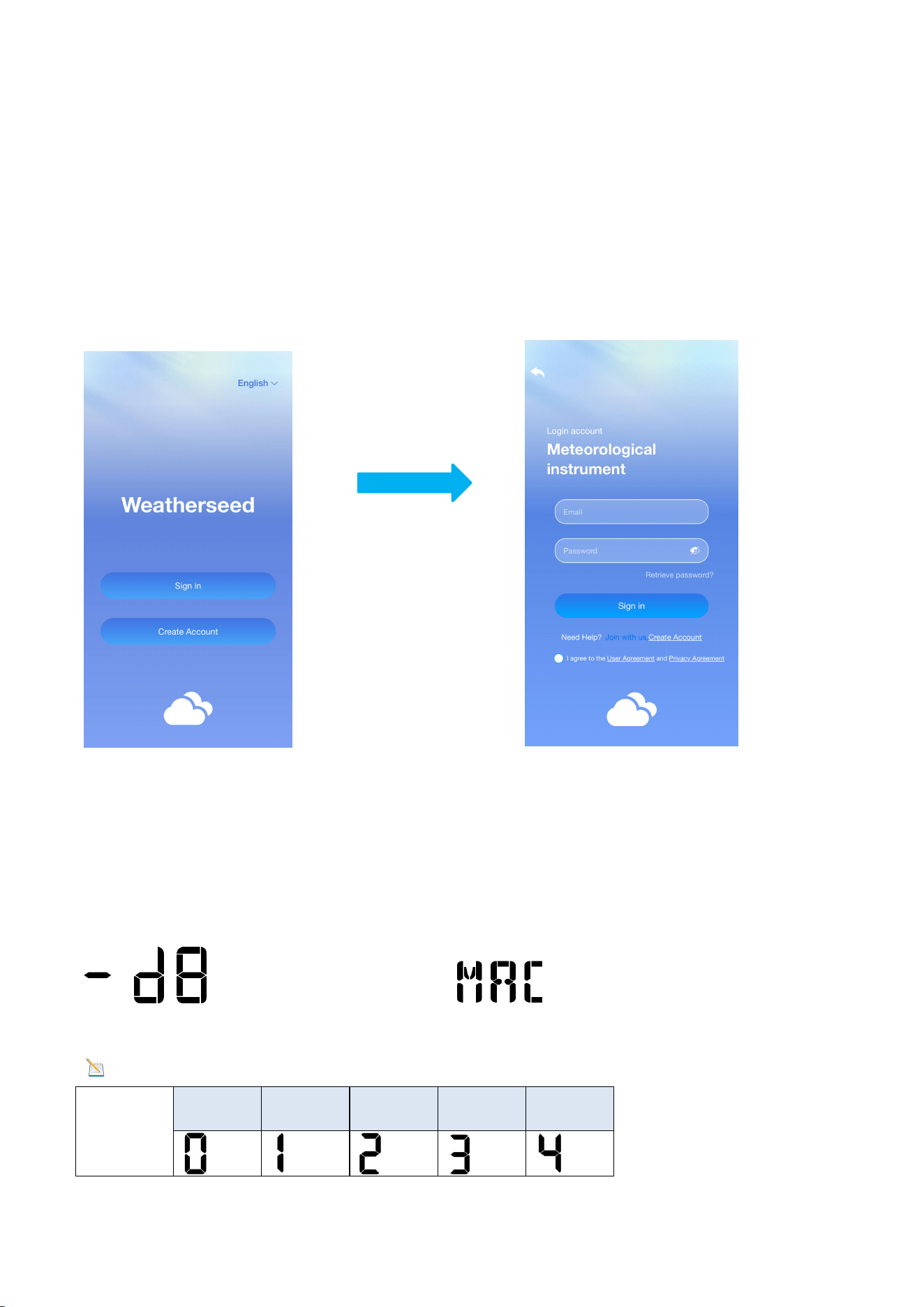
8.4. MAC Address
In normal mode, Press and hold the MAX/MIN key on the display, the MAC icon will
be shown in the date area (as shown in the figure), the MAC address will flash one by
one in sequence, and it will automatically return to the normal mode when all the
addresses are displayed.
Note: Comparison table of numbers and letters
Numbers
0
1
2
3
4
25
5
6
7
8
9
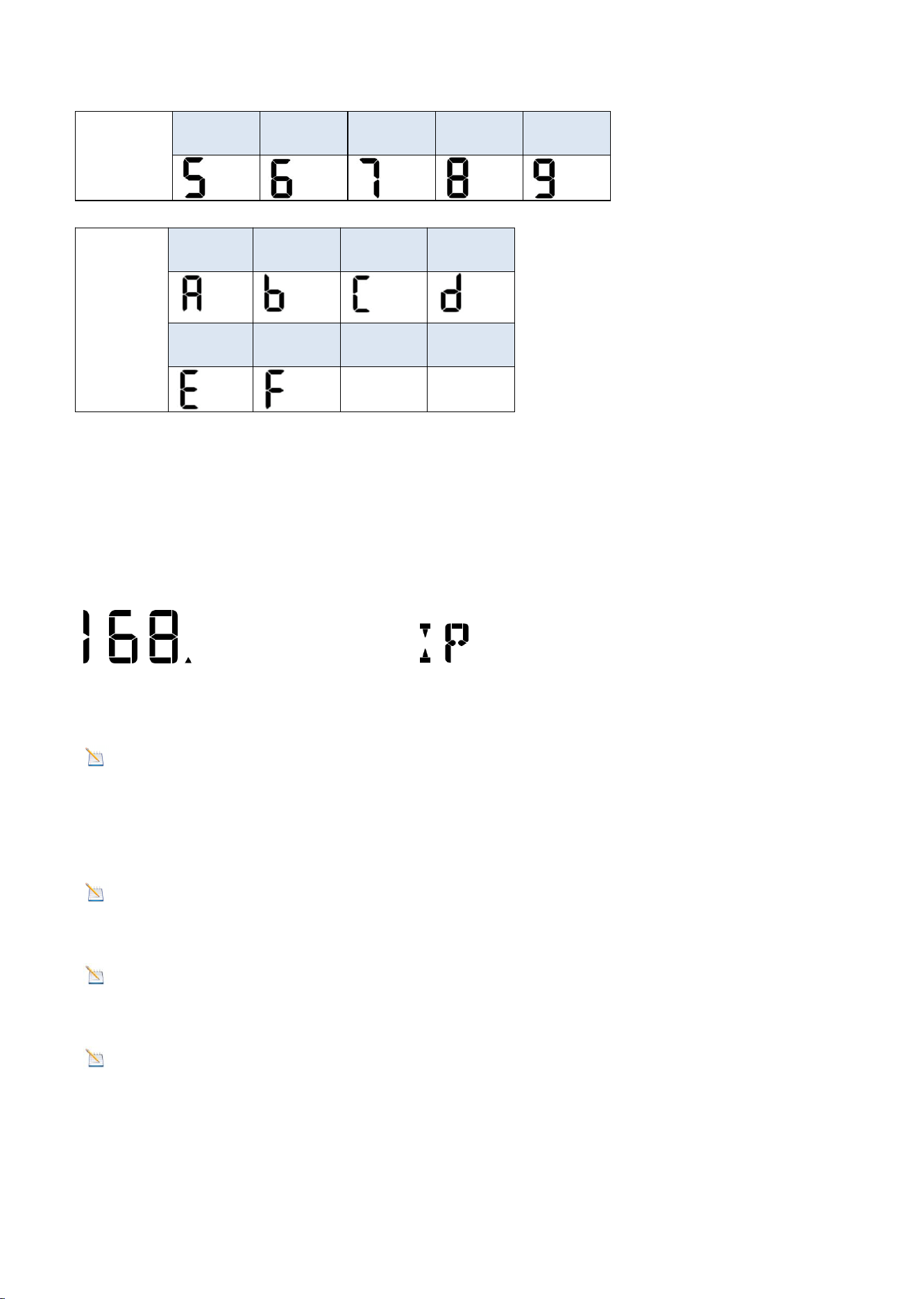
Letters
A
b
C
d
E
F
8.5. IP Address
In normal mode, Press and hold the PRESSURE- key on the display, the IP icon will be
shown in the date area (as shown in the figure), the IP address will flash in sequence
one by one, and it will automatically return to normal mode when all the addresses
are displayed.
8.6. Connecting Steps
Note: The display console only supports 2.4 GHz signals. If you have a dual-band
router (supporting both 2.4 GHz and 5.0 GHz bands), ensure that the 2.4 GHz band is
enabled and can be distinguished from the 5.0 GHz channel's SSID for accurate
connection to the 2.4 GHz channel.
Note : The power adapter must be plugged in to connect to WiFi.
Battery power alone cannot connect the device to WiFi.
Note:Please don't select the wrong device type or model. If you choose the
wrong one, the network will not connect successfully.
Note:The QR code is located on the back of the console.
26
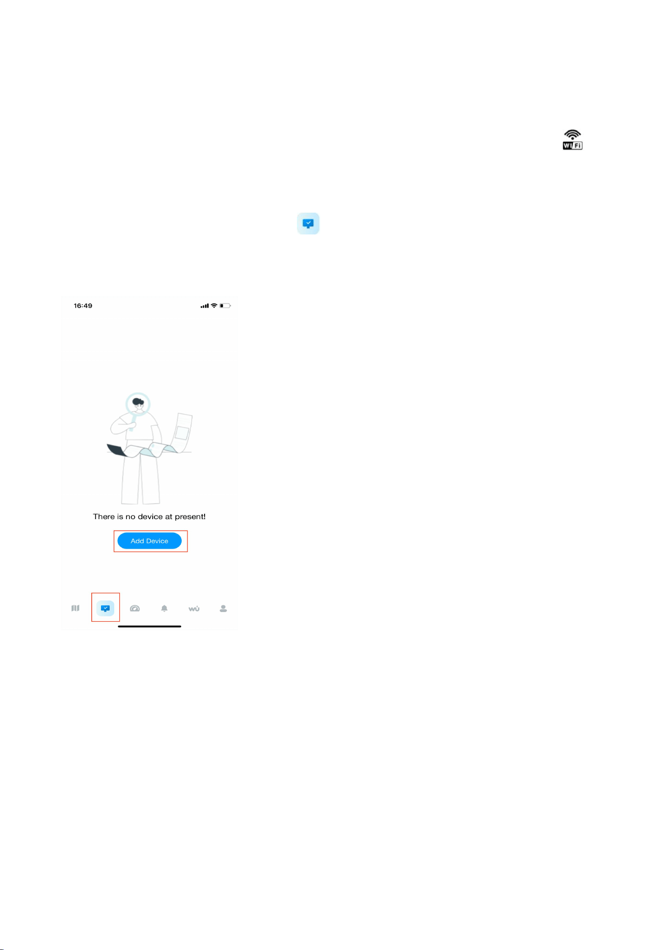
8.6.1 Bluetooth Distribution Network Mode
To enter the distribution mode, press and hold the WIND + key. The WiFi icon will
flash, and the BI icon will be shown in the date area, indicating that the display has
entered the “Bluetooth Distribution Network” mode.
After the display has entered the “Bluetooth Distribution Network” mode, please
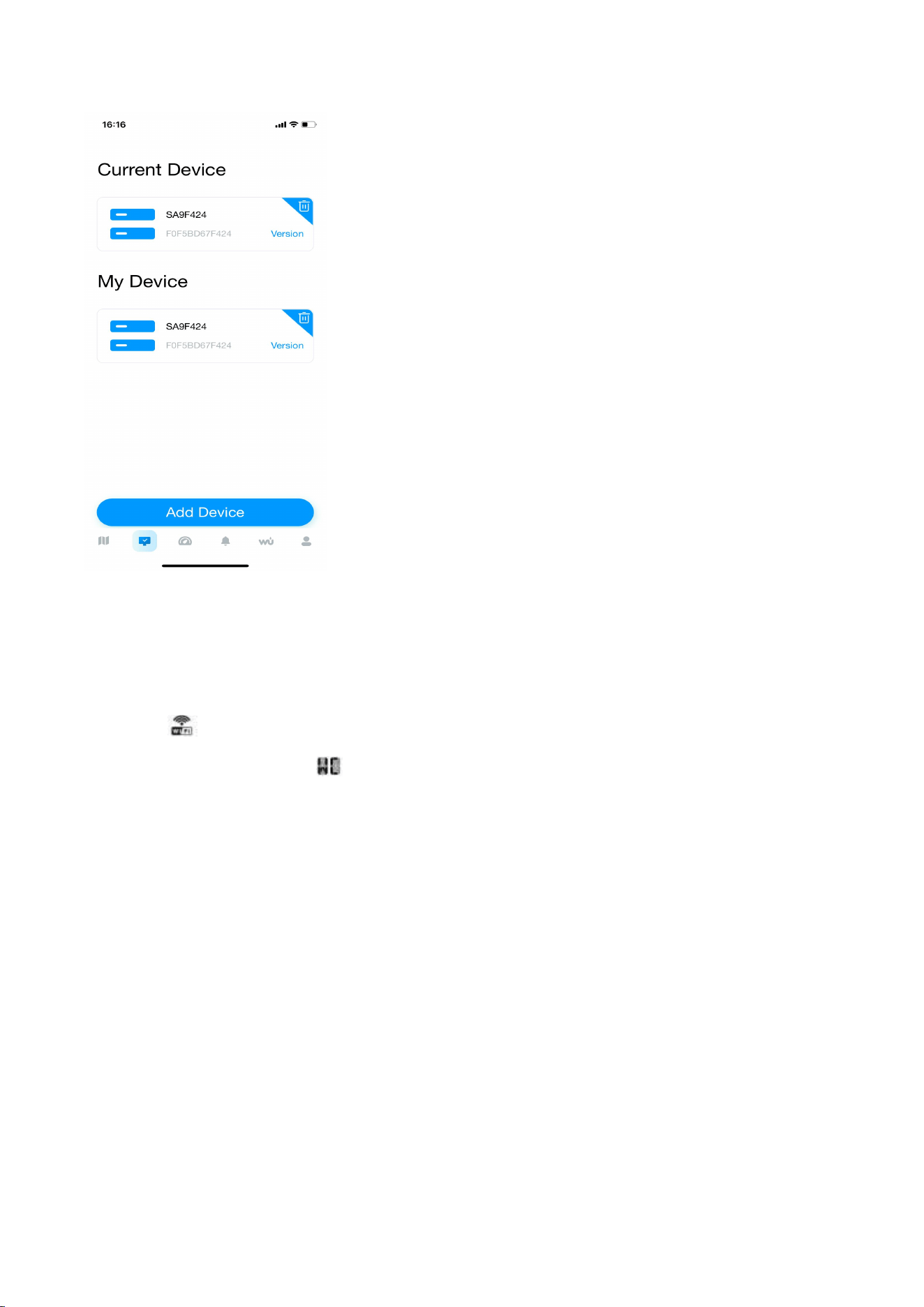
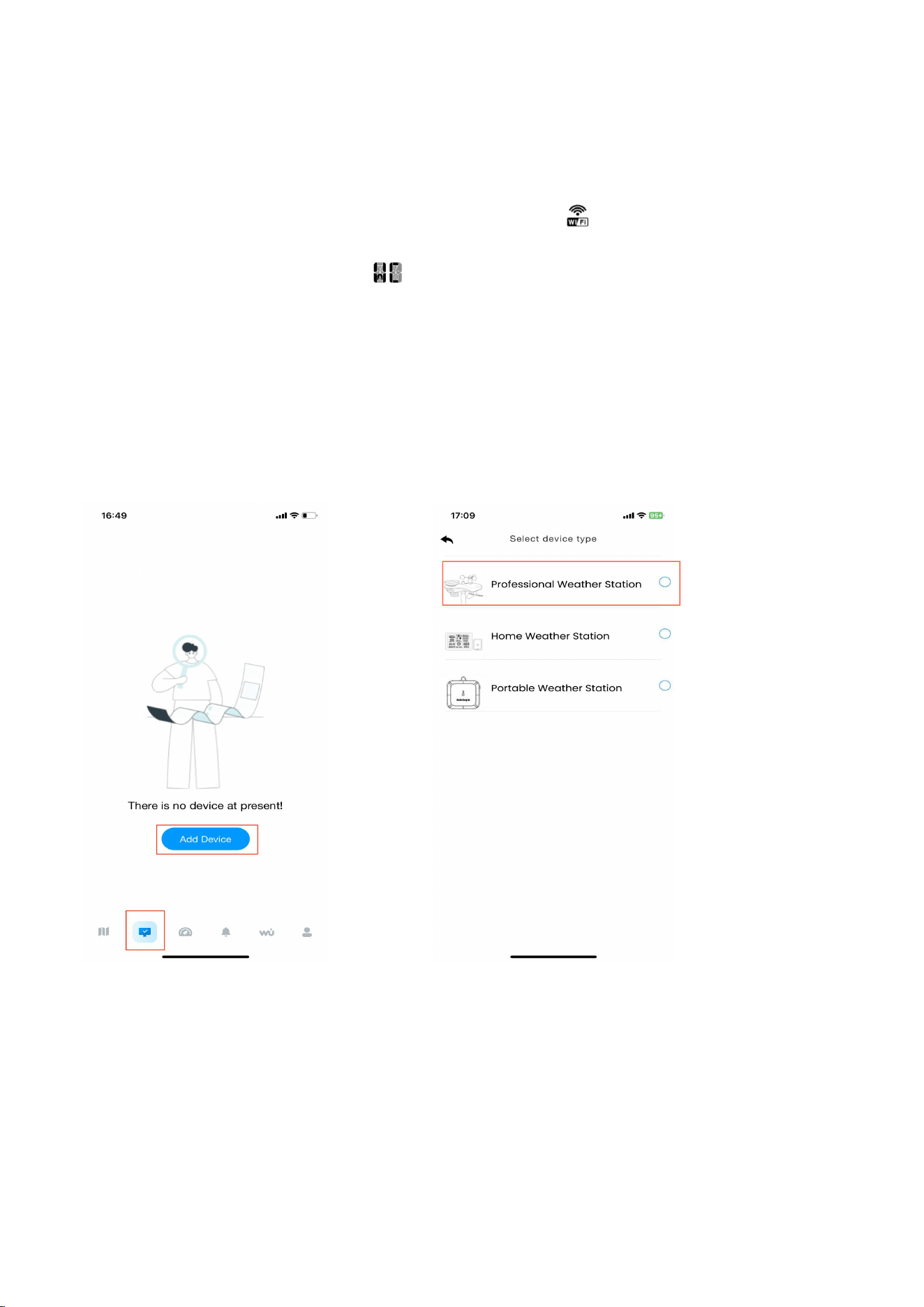
open the app. Select the second icon on the lower left to enter the networking
interface to start networking. The specific steps are as follows:
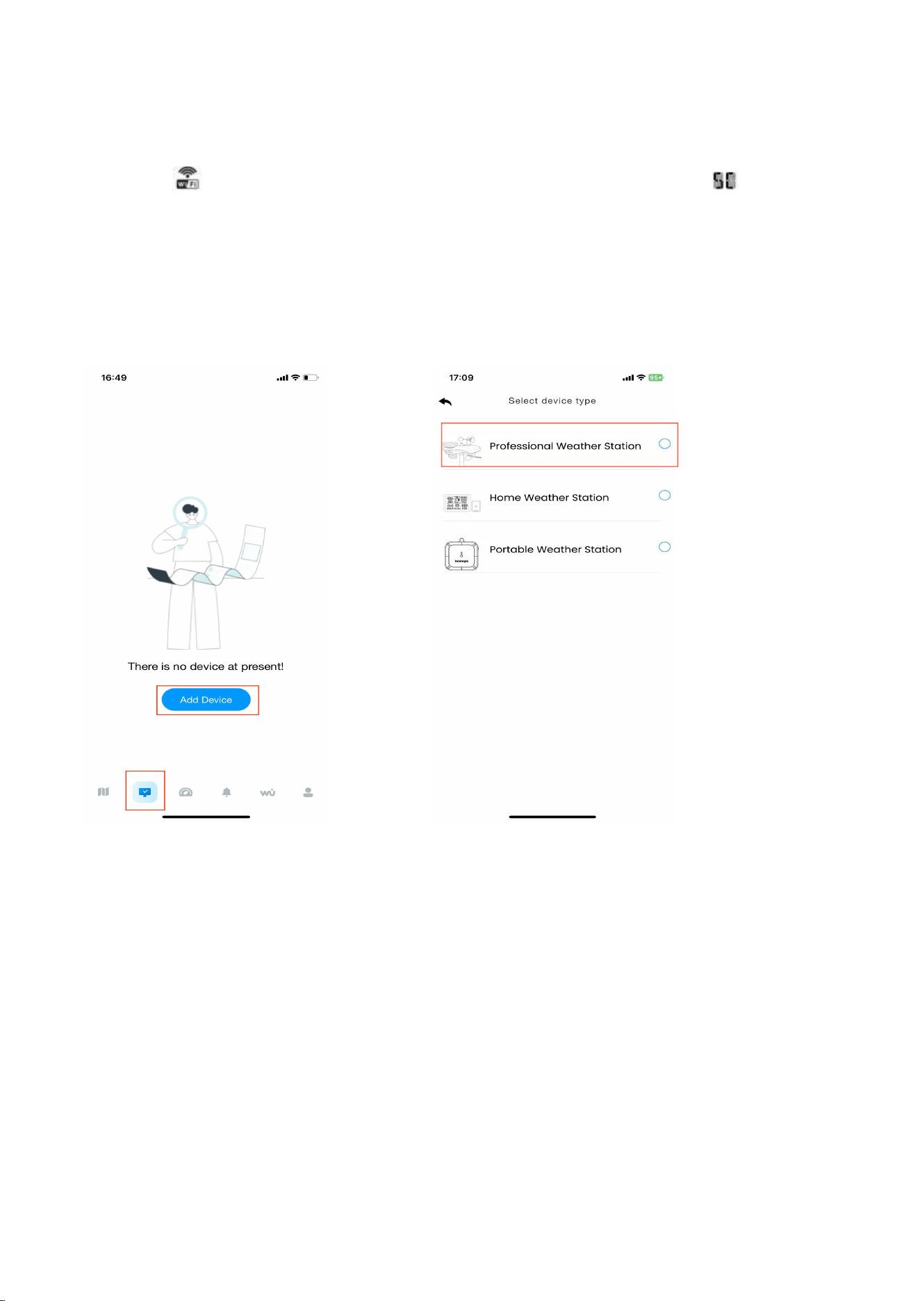
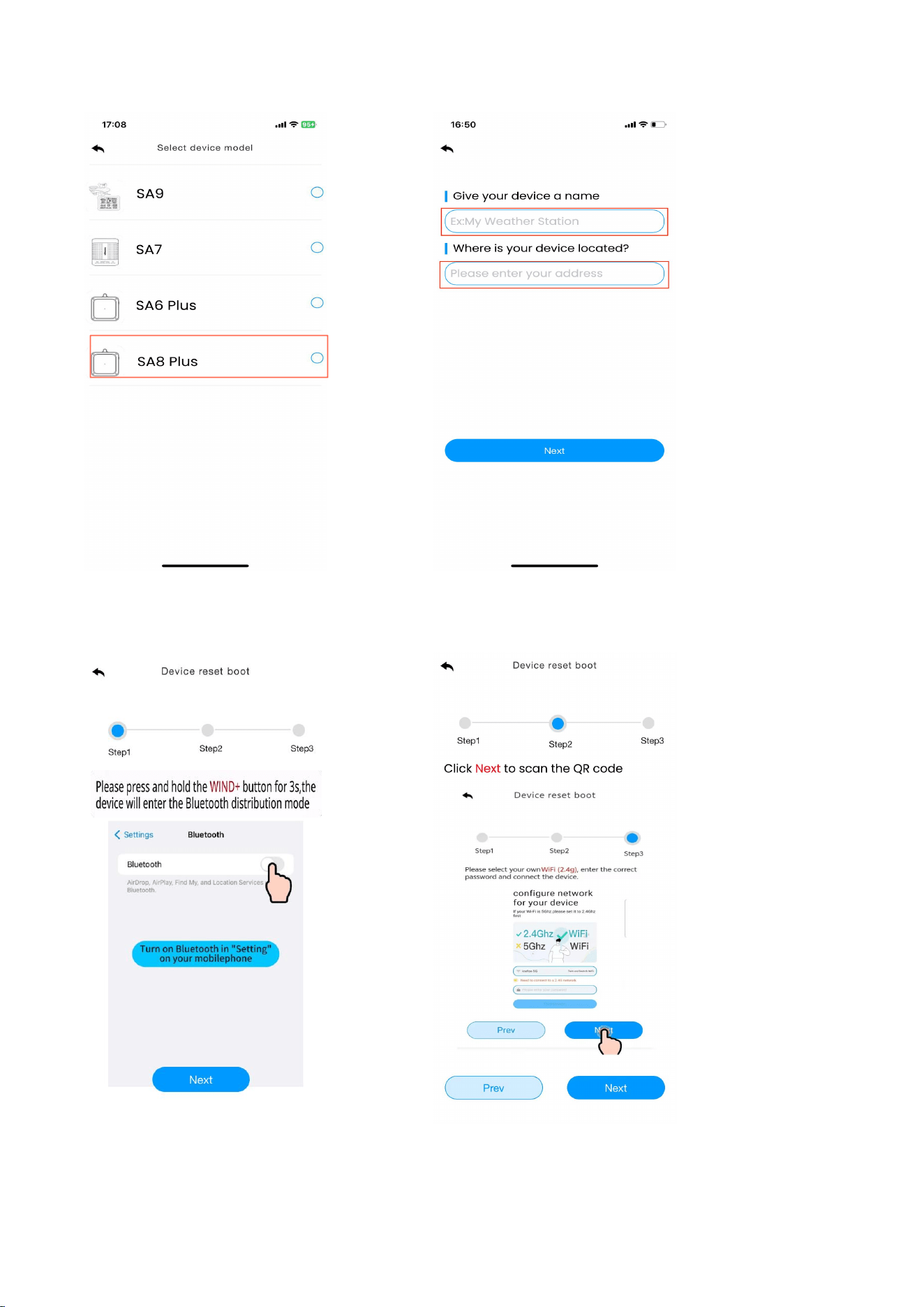
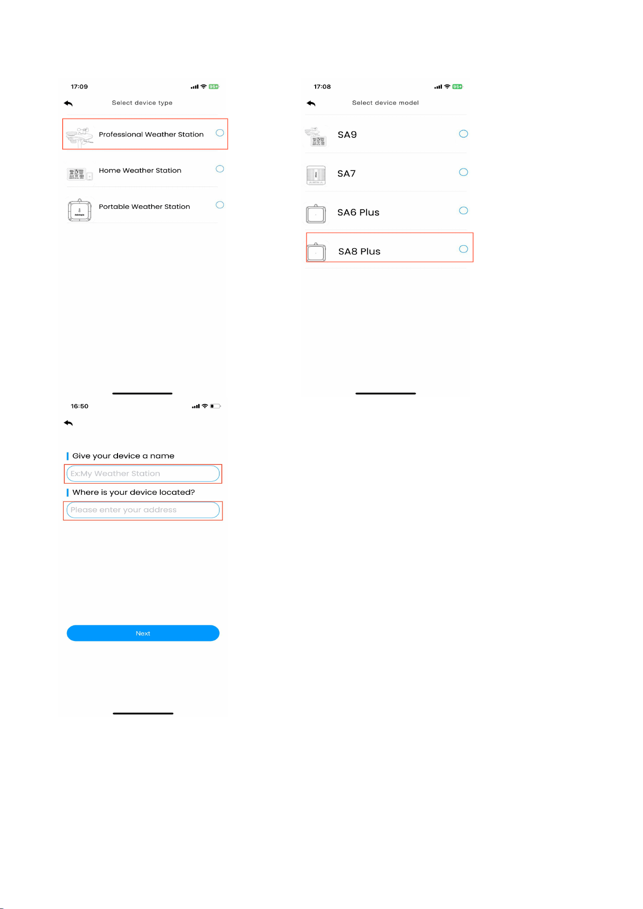
(1) Enter the networking interface. Click "Add Device" to start connecting to the WiFi.
(2)Add the device in the app. Select the device type and model. Then, set a weather
station name, and enter your location.

27
Note
:
Device and location naming requirements: Only numbers, upper and lower
case letters. Maximum 20 characters, spaces allowed. Symbols prohibited. Spaces are
included in the 20 characters.
28
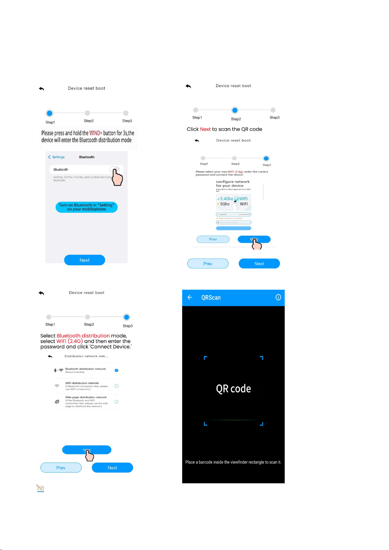
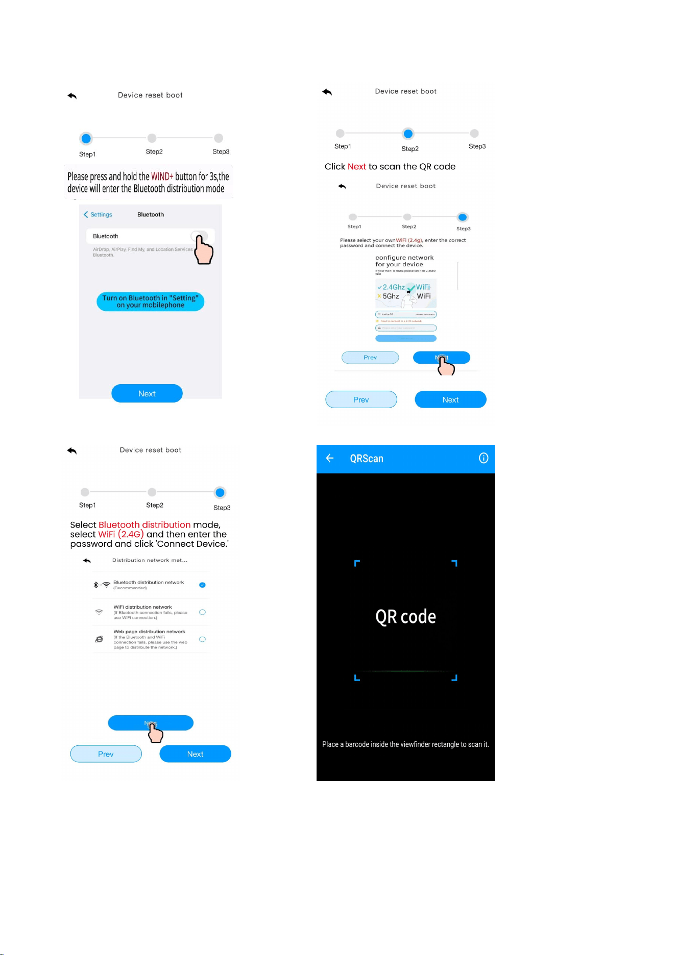
(3) Enter the network configuration interface and click “Next” to complete the three
steps of network configuration. Then, scan the QR code (MAC address) of the device.
Note
:
The QR code is at the back of the Console.
29
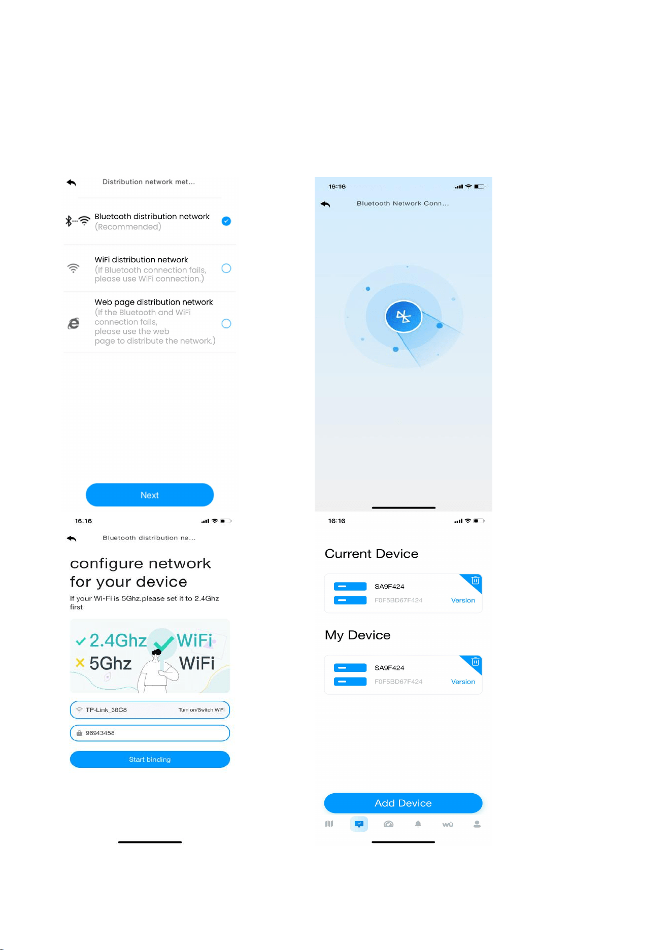
(4)Select “Bluetooth Distribution Network” mode to automatically search for
Bluetooth signals and pairing.
After successful pairing, jump to the WiFi interface. Please select 2.4ghz WiFi, enter
the password.
30
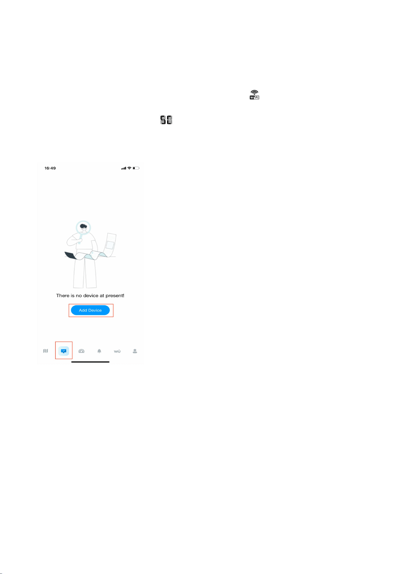
8.6.2. WiFi Distribution Network Mode
In normal mode, press and hold WIND+ key for at least 3 seconds to enter the
“Bluetooth Distribution Network” Mode, the WiFi icon will be flashing and the BI
icon will be displayed in the date area, then short press the SET key once, the BI icon
will be converted to the SC icon , which indicates that the display has entered the
“WiFi Distribution Network” mode.
(1) Enter the networking interface. Click "Add Device" to start connecting to the WiFi ;
(2) Add the device in the app. Select the device type and model, set a weather station
name, and enter your location.
31
(3) Enter the network configuration interface and click “Next” to complete the three
steps of network configuration. Then, scan the QR code (MAC address) of the device.
32
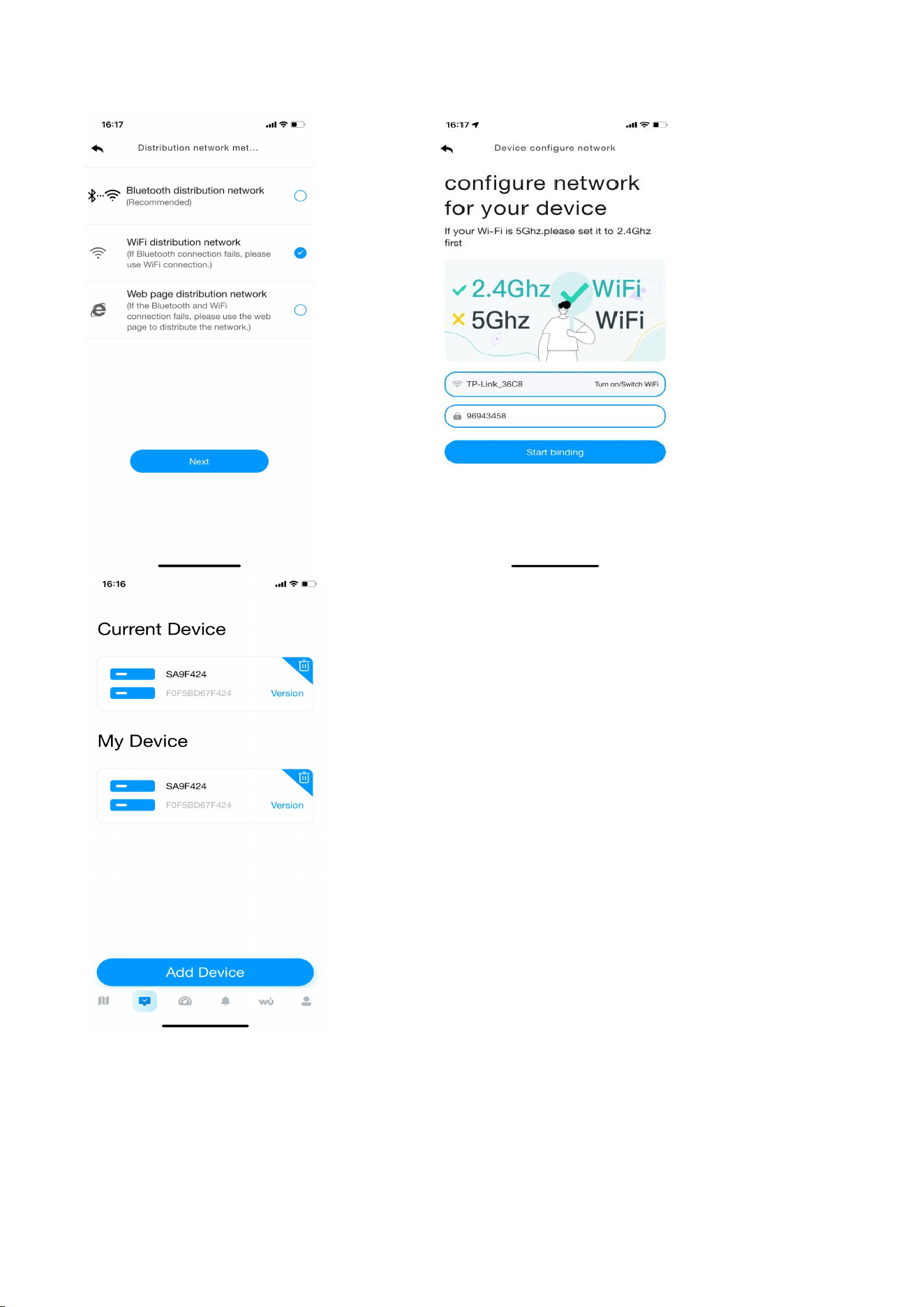
(4)Select the “WiFi Distribution Network” mode.
Select your own WiFi (2.4g), enter the correct password and connect the device.
After the connection is successful, return to the Device page.
33
34
8.6.3. Web page distribution network mode
In normal mode, press and hold WIND+ key for at least 3 seconds to enter the
“Bluetooth Distribution Network” mode, the WiFi icon will be flashing and the BI
icon will be displayed in the date area, then short press the SET key twice, the icon
will be converted to the WC icon , which indicates that the display has entered the
“WiFi Distribution Network” mode.
After the display has entered the “Web Page Distribution Network” mode, please
follow the steps below and the picture instructions to connect:
(1) Add a device in the dashboard interface. Select device type and model, set a
weather station name, and enter your location. Enter the network configuration
interface, then click “Next” to complete the three steps of network configuration.
35
(2) Enter the network configuration interface and click “Next” to complete the three
steps of network configuration. Scan the QR code.
36
(3) Select the “Web Page Distribution Network” mode , Click “Go” to connect WiFi.
Then device will automatically jump to the WiFi list screen. Connect to the
“weatherseed” WiFi.
37
Return to the app. Click the confirmation dot, and click “Next”. Please select 2.4ghz
WiFi, enter the password, and click “Connect”.
38
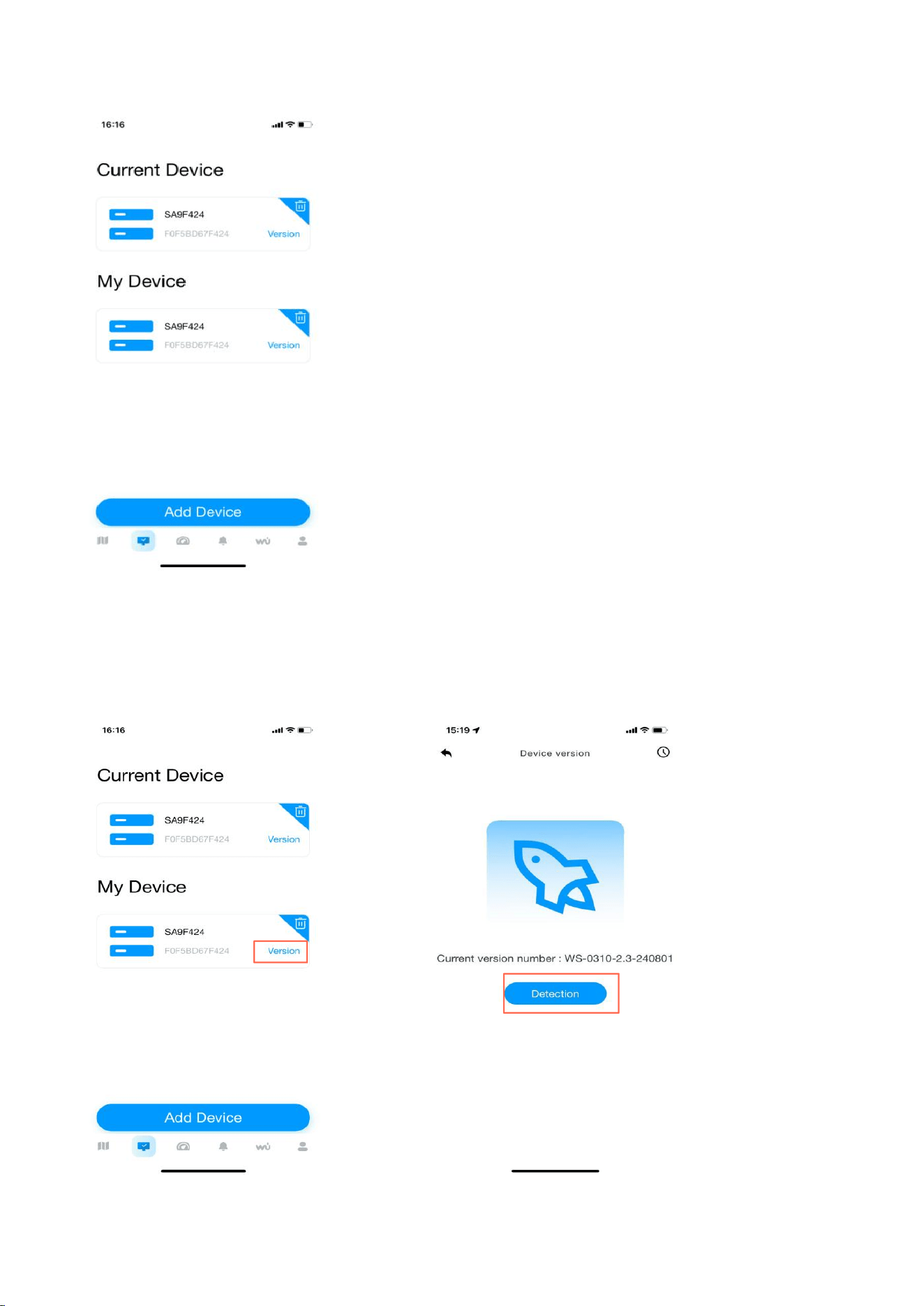
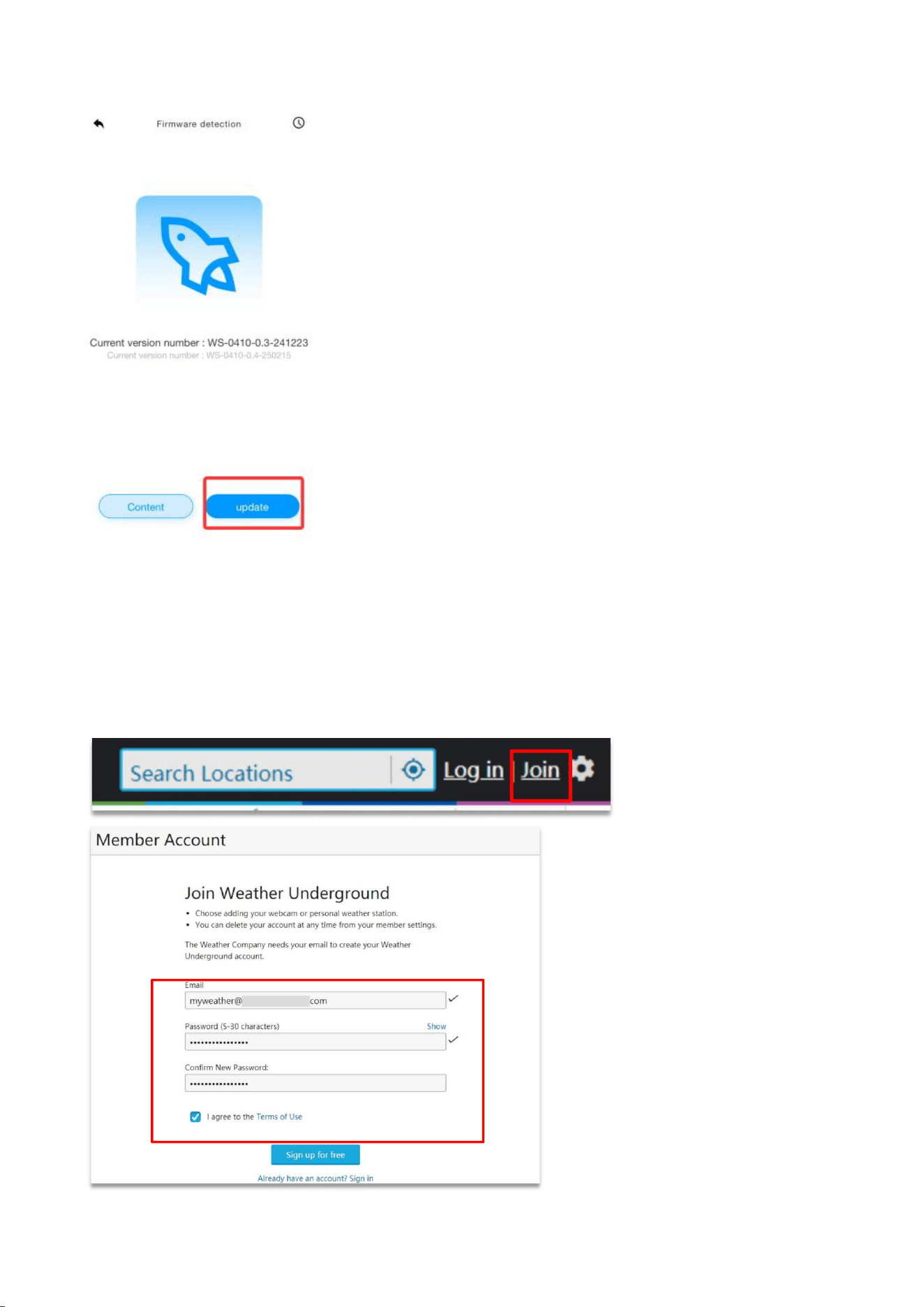
8.7. Firmware Upgrade
When your app receives a firmware upgrade notification, follow the steps below to
upgrade the firmware remotely:
39
8.8. Sign Up on Wunderground.com
1. Visit the “https://www.wunderground.com” website. Click the “Join" button,
input your e-mail and password, and select the “Sign up for free” button to create
your own account.
40
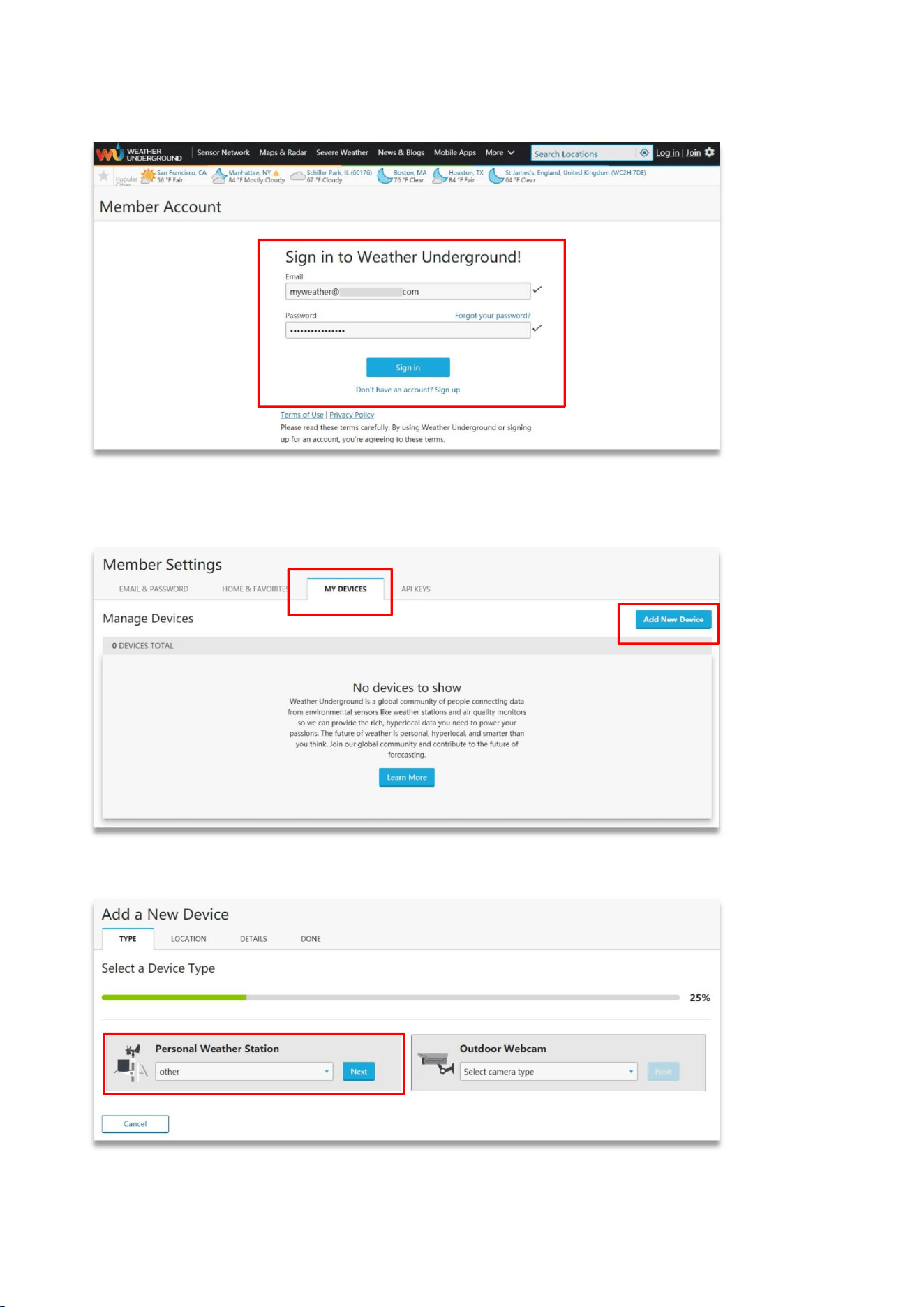
2. Click the “Sign in” button to log in, and switch to the Member Settings page.
3. Select the My Devices tab and click “Add New Devices”.
Note: On the “Add New Devices" page, set the “TYPE”, “LOCATION", “DETAILS”, and
“DONE" pages step-by-step until 100% completed.
4. On the TYPE page, click the “Personal Weather Station” drop-down list to select
“Other”.
41
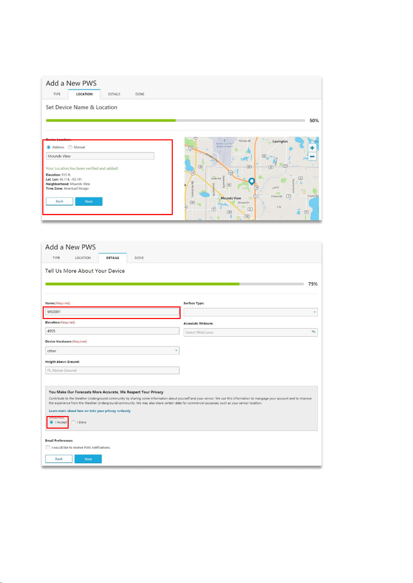
5. On the LOCATION page, select the “Address” or “Manual” Option, find and input
your local position, then press “Next”.
6. On the DETAILS page, fill in the “Required” information, then press “Next”.
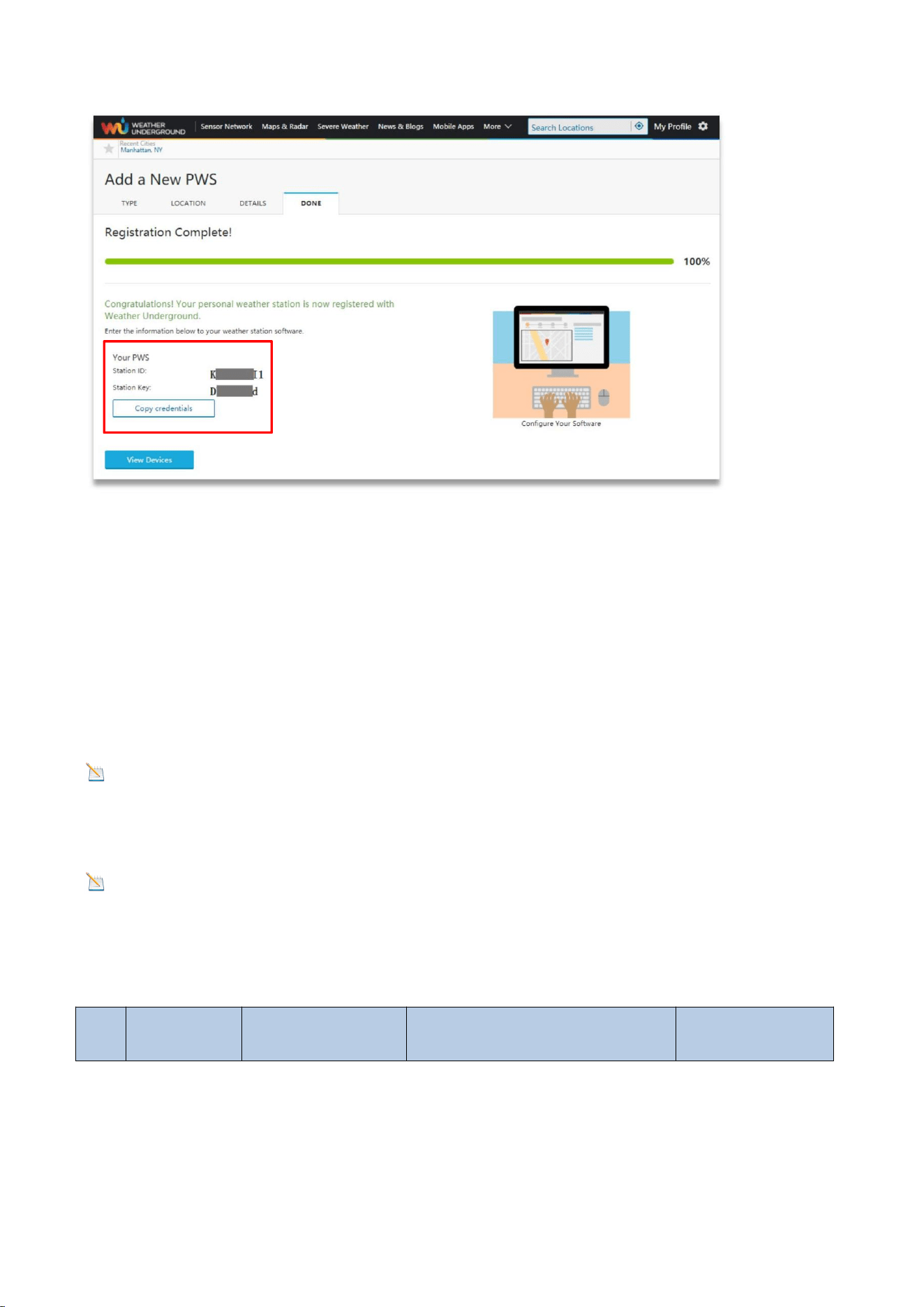
7. On the DONE page, the device “Station lD” and “Station Key” are shown. Copy
and record the information for later use.
42
9. Display Console Operation
9.1. Set Mode
In normal mode, press and hold the SET key for at least 3 seconds to enter set mode
and the first setting will flash. To skip any step to the next setting, keep pressing the
SET key and the current setting parameter will flash.
NOTE: In Set Mode, press the WIND+ key or the PRESSURE- key to change or
scroll the setup value. Press and hold the WIND+ key or PRESSURE- key for three
seconds to quickly increase or decrease.
NOTE: To exit Set Mode at any time, press the LIGHT SNOOZE key on the display
console.
The sequence and commands for the Set mode are summarized in the following
charts:
NO
Command
Mode
Settings
Image
43
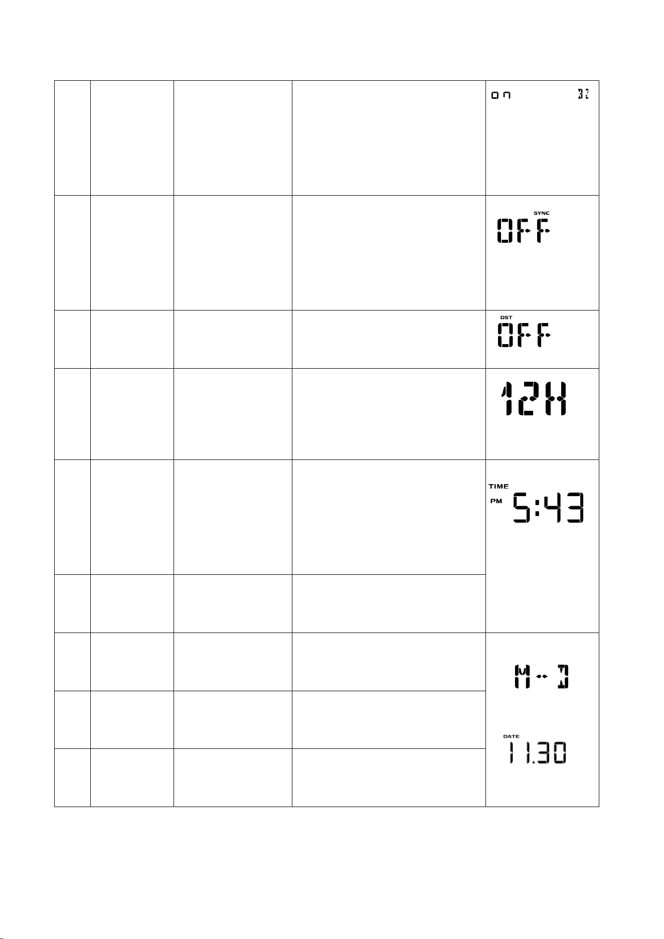
1
[SET]+3
sec
Enter Set Mode,
Beep On or Off
Press [WIND +] or
[PRESSURE/-] to switch OFF
and ON.
This will prevent the beep
from sounding when
pressing any button
2
[SET]
Time SYNC
- Press the[WIND +] key or
[PRESSURE/-] to toggle the
synchronized time on/off.
- Synchronize the device
with the time and date via
WiFi.
3
[SET]
DST
Press the [WIND +] or
[PRESSURE/-] to toggle DST
on/off.
4
[SET]
12/24-Hour
Format
Press the [WIND +] or
[PRESSURE/-] key to toggle
between 12-hour and 24-
hour.
5
[SET]
Hour
Press the [WIND +] or
[PRESSURE/-] key to adjust
the hours up or down.
The PM icon will be
displayed during the
afternoon hours.
6
[SET]
Minute
Press the [WIND +] or
[PRESSURE/-] key to adjust
the minutes up or down.
7
[SET]
Date Format
(default: M-D)
Press the [WIND +] or
[PRESSURE/-] key to toggle
between M-D and D-M.
8
[SET]
Month
Press the [WIND +] or
[PRESSURE/-] key to adjust
the calendar month.
9
[SET]
Day
Press the [WIND +] or
[PRESSURE/-] key to adjust
the calendar day.
44
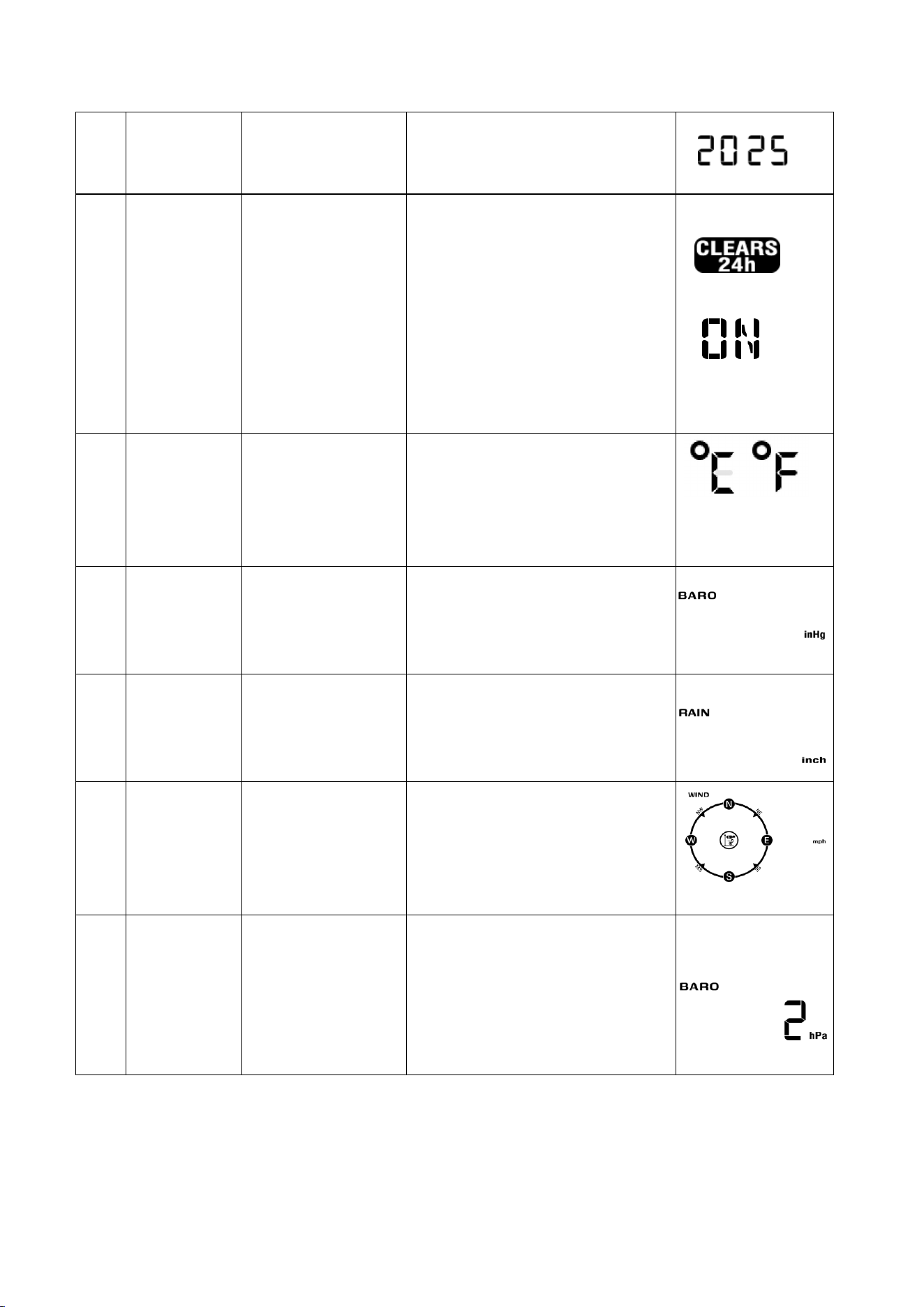
10
[SET]
Year
Press the [WIND +] or
[PRESSURE/-] key to adjust
the calendar year.
11
[SET]
Max/Min
Clearing
(default: ON)
The maximum/minimum
value can be set to daily
(midnight) or manually
cleared.
Press the [WIND +] or
[PRESSURE/-] key to toggle
between ON (24-hour
clearing) and OFF (manual).
12
[SET]
Temperature
Measurement
Unit
(default value:
°F)
Press the [WIND +] or
[PRESSURE/-] keys to toggle
between °F and °C
measurement units.
13
[SET]
Barometric
Pressure unit
(default value:
InHg)
Press the [WIND +] or
[PRESSURE/-] key to toggle
the pressure unit between
mmhg, inHg or hPa.
14
[SET]
Rainfall
Measurement
Unit (default
value: inch)
Press the [WIND +] or
[PRESSURE/-] key to toggle
the rainfall unit between
mm and inch.
15
[SET]
Wind Speed
Measurement
Unit (default
value: mph)
Press the [WIND +] or
[PRESSURE/-] key to toggle
the wind speed unit
between m/s, km/h, mph,
knots bft or ft/s.
16
[SET]
Pressure
Threshold
Setting
(default value: 2
hPa)
Press the [WIND +] or
[PRESSURE/-] key to change
the pressure threshold from
2 hPa to 4 hPa. (See 11.3 for
more information on this
section).
45
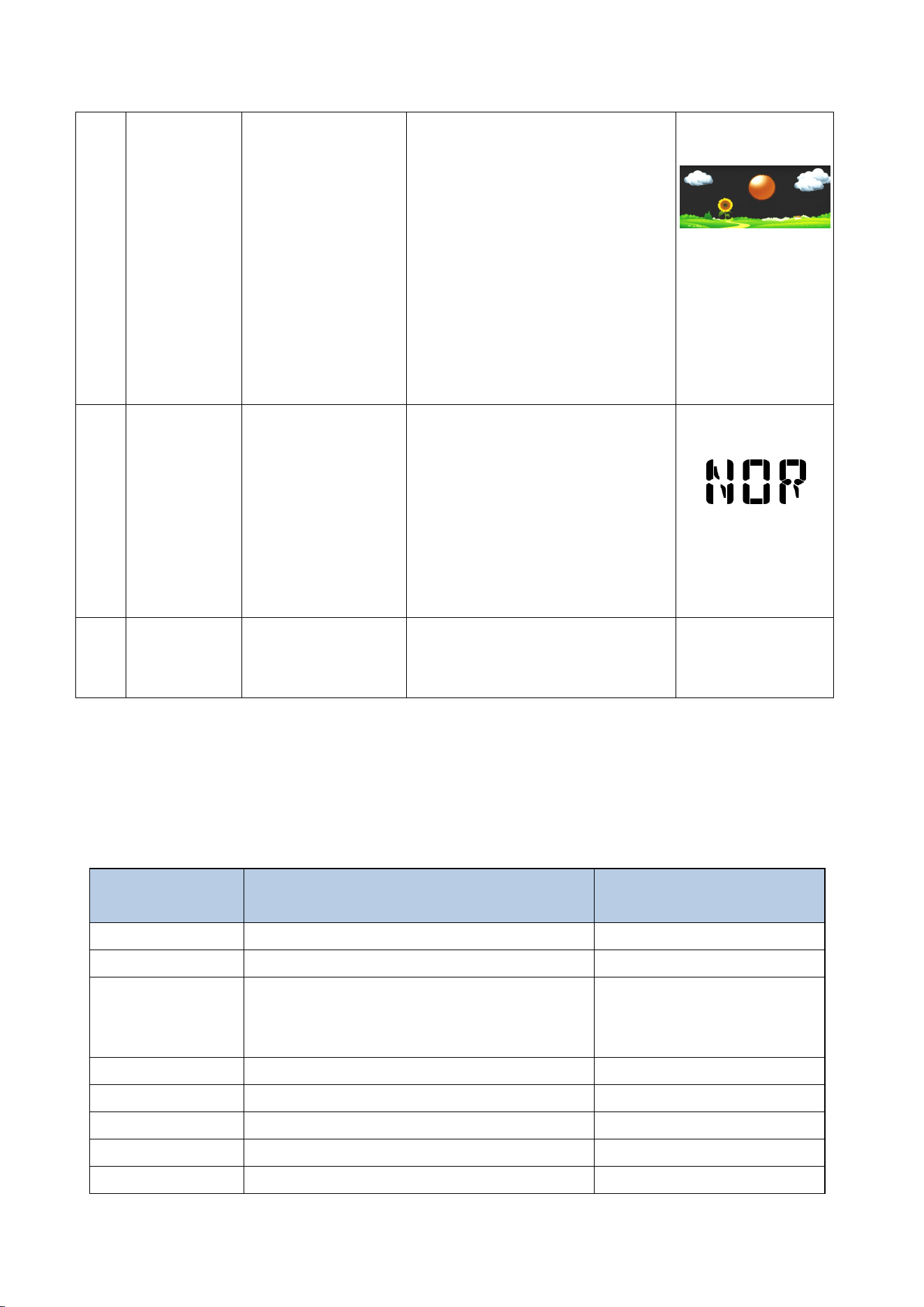
17
[SET]
Weather Icon
Settings
Press the [WIND +] or
[PRESSURE/-] key to select
the initial weather icon for a
sunny, less cloudy, cloudy,
or rainy day (see 11.1 for
more information on this
section).
Note: The weather icon
does not change
immediately, wait 4 hours
for it to change.
18
[SET]
Location Area
(default value:
Northern
Hemisphere)
Press the [WIND +] or
[PRESSURE/-] key to toggle
the geographic location of
the Northern Hemisphere
(NOR) or Southern
Hemisphere (SOU). (Refer to
5.3 Sensor Mounting
Orientation).
19
[SET]
Exit Set Mode
Press the SET or LIGHT
SNOOZE key to exit setup
mode.
*[SET] + 3 seconds means press and hold the SET button for three seconds.
*[SET] means press the SET button.
9.2. Time Zone
The following table summarizes time zones around the world:
Hours from
GMT
Time Zone
Cities
-12
IDLW: International Date Line West
---
-11
NT: Nome
Nome, AK, USA
-10
AHST: Alaska-Hawaii Standard
CAT: Central Alaska
HST: Hawaii Standard
Honolulu, HI, USA
-9
YST: Yukon Standard
Yukon Territory
-8
PST: Pacific Standard
Los Angeles, CA, USA
-7
MST: Mountain Standard
Denver, CO, USA
-6
CST: Central Standard
Chicago, IL, USA
-5
EST: Eastern Standard
New York, NY, USA
46
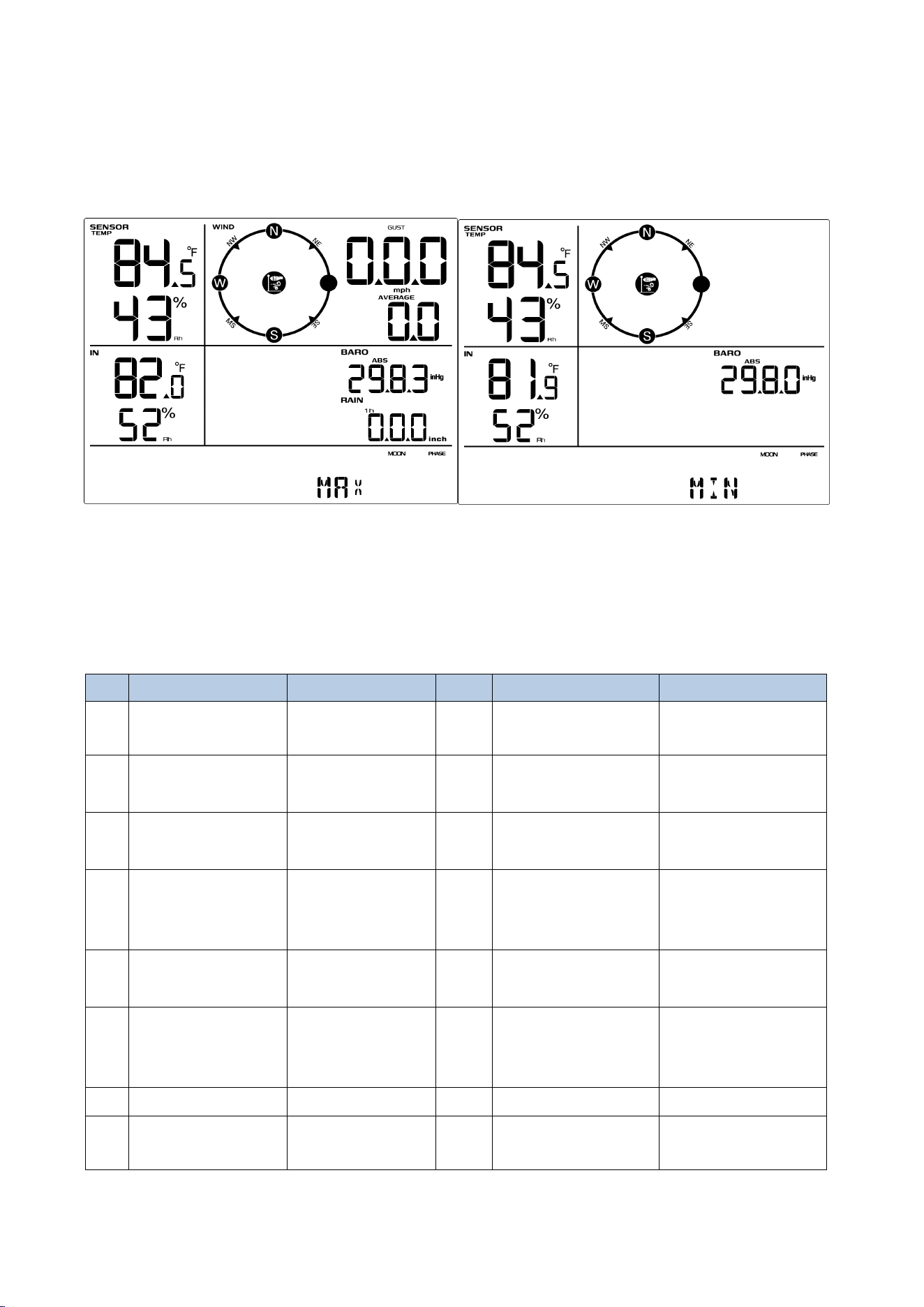
9.3. Viewing Max/Min Mode
In normal mode, press the MAX/MIN key once briefly, the MAX icon will be shown in
the date area, and the display will show the maximum values for rainfall rate, gust
and average wind speed, ABS barometric pressure, outdoor temperature, humidity,
and indoor temperature, humidity. As shown in Figure 22(a).
To view the MIN values, press the [MAX/MIN] button again, and the minimum values
will be displayed, as shown in Figure 22 (b).
To clear the minimum values, press and hold the [MAX/MIN] button while the
minimum values are displayed.
-4
AST: Atlantic Standard
Caracas, Venezuela
-3.5
Newfoundland Time (NT)
Newfoundland, Canada
-3
---
São Paulo, Brazil
-2
AT: Azores
Azores, Cape Verde
Islands
-1
WAT: West Africa
---
0
GMT: Greenwich Mean
WET: Western European
London, England
1
CET: Central European
Paris, France
2
EET: Eastern European
Athens, Greece
3
BT: Baghdad
Moscow, Russia
3.5
Iran Standard Time (IRST)
Tehran, Iran
4
---
Abu Dhabi, UAE
5
---
Tashkent, Uzbekistan
5.45
Nepal Standard Time
Nepal
5.5
Indian Standard Time (IST)
India
6
---
Astana, Kazakhstan
7
---
Bangkok, Thailand
8
CCT: China Coast
Beijing, China
9
JST: Japan Standard
Tokyo, Japan
9.5
Australian Central Standard Time
(ACST)
Adelaide, Australia
10
GST: Guam Standard
Sydney, Australia
11
---
Magadan, Russia
12
IDLE: International Date Line East
NZST: New Zealand Standard
Wellington, New
Zealand
47
Press the LIGHT SNOOZE key to exit the Max/Min View and Reset mode and return to
the normal display mode.
Figure 22(a) Figure 22 (b)
9.4. Alarm Mode
The weather station contains the following alarms:
No
Parameter
Default
No
Parameter
Default
1
Time (Alarm 1
and Alarm 2)
00:00
10
24-hour Rainfall
50.0mm
2
Outdoor
Temperature
HI:30℃
Low:-10℃
11
Absolute
Pressure
HI:1040.0hpa
Low:960.0hpa
3
Outdoor
Humidity
HI:75%
Low:45%
12
Relative
Pressure
HI:1040.0hpa
Low:960.0hpa
4
Outdoor
Apparent
Temperature
HI:26.7℃
Low:0.0℃
13
Indoor
Temperature
HI:20.0℃
Low:0.0℃
5
Outdoor Dew
Point
HI:10.0℃
Low:-10.0℃
14
Indoor Humidity
HI:65%
Low:35%
6
Outdoor Feels
Like
Temperature
HI:26.7℃
Low:0.0℃
15
Indoor Dew
Point
HI:10.0℃
Low:-10.0℃
7
Wind Speed
HI:10.0 m/s
8
Average Wind
Speed
HI:5.0 m/s
48
9.4.1. Alarm Trigger
If the current value reaches the alarm condition, the alarm icon will flash (visual) and
the alarm buzzer will sound (audible).
To turn off the buzzer, press any key.
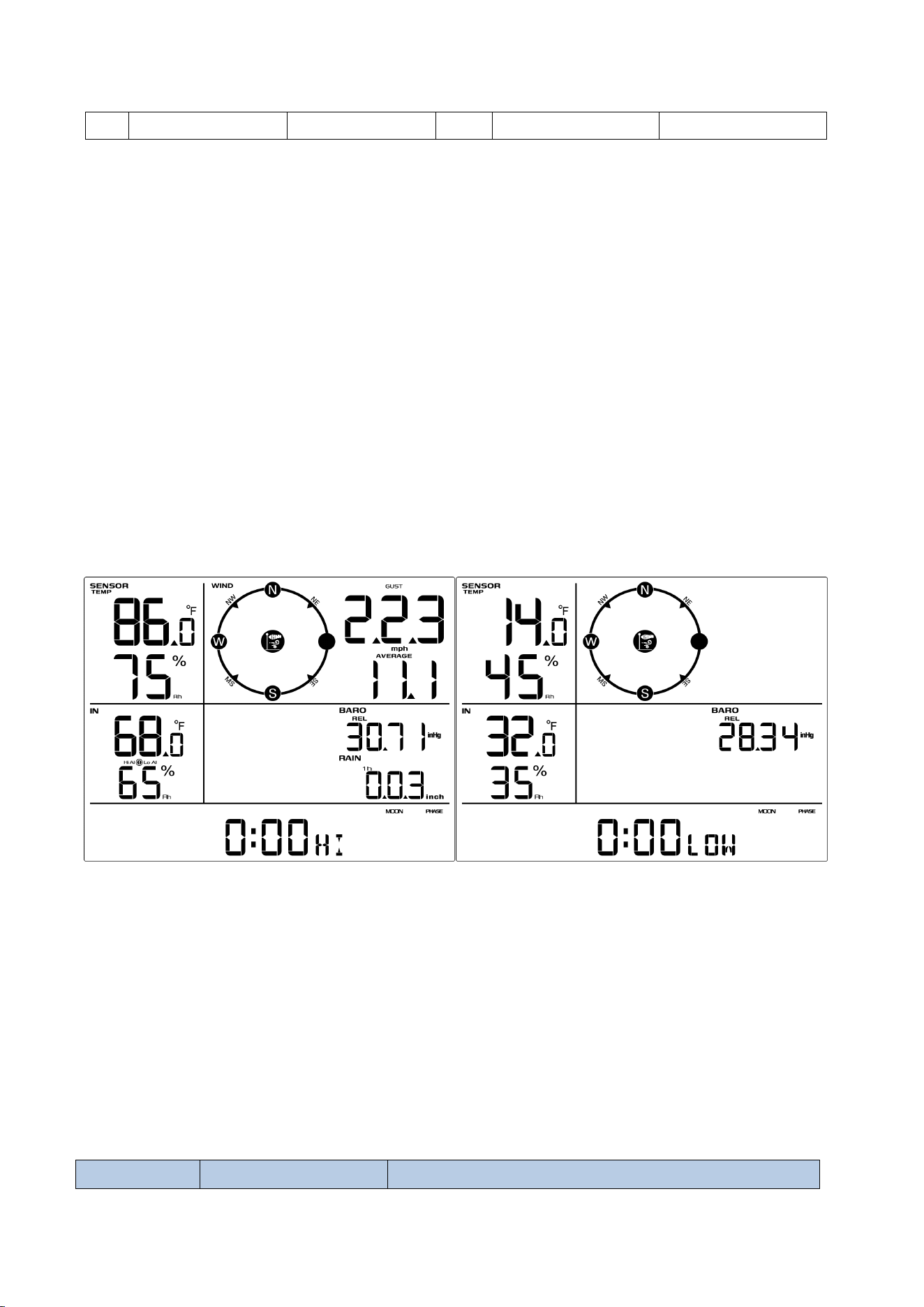
9.4.2. Viewing High/Low Alarm Values
To view the high alarm settings, press (do not hold) the [ALARM] button, and the high
alarms will be displayed, as shown in Figure 23 (a).
To view the low alarm settings, press the [ALARM] button again, and the low alarms
will be displayed, as shown in Figure 23 (b).
To return to normal mode, press the [ALARM] button again.
Figure 23 (a) Figure 23(b)
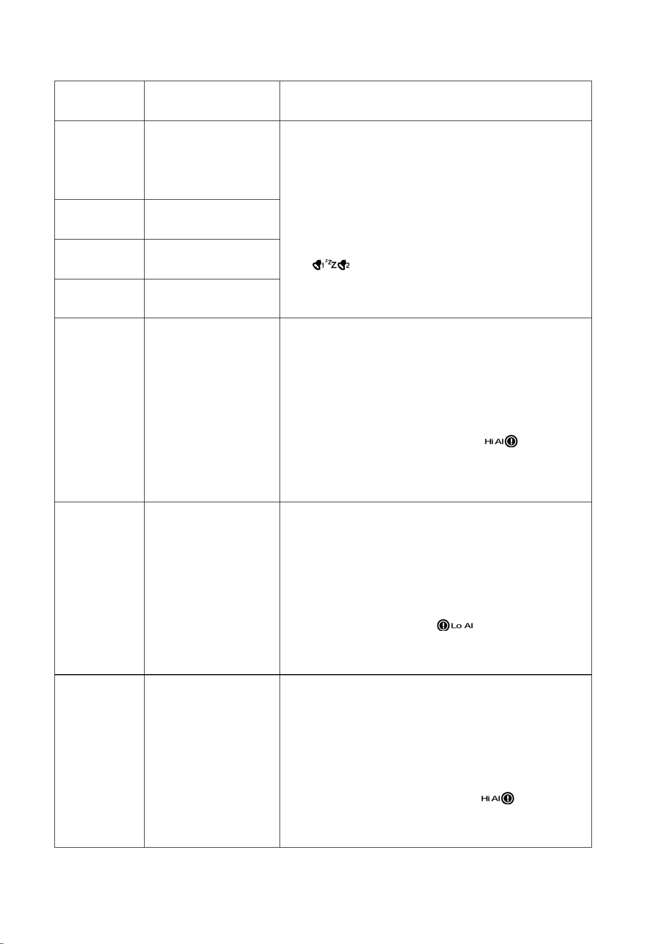
9.4.3. Setting High/Low Alarms
Press and hold the [ALARM] button for three seconds to enter the ALARM Set Mode.
To save and proceed to the next
alarm setting, press (do not hold) the SET button.
The following diagrams summarize the sequence and instructions for setting alarms.
Command
Mode
Settings
9
Rainfall Rate
1.0 mm/h
49
[ALARM]+3
seconds
Enter Alarm Set
Mode
[SET]
Enter Alarm
Setting Mode;
Hour Setting
(Alarm 1)
·Press the WIND+ button or the PRESSURE-
button to increase or decrease the value. Long
press to increase or decrease quickly.
·Press the ALARM button to turn the time
alarm on or off.
When the alarm is on, the alarm time
icon will be displayed; when the alarm is
off, the alarm time icon will disappear.
[SET]
Minute Setting
(Alarm 1)
[SET]
Hour Setting
(Alarm 2)
[SET]
Minute Setting
(Alarm 2)
[SET]
Outdoor
Temperature High
Alarm
·Press the WIND+ key or the PRESSURE- key to
increase or decrease the value. Long press to
increase or decrease quickly.
·Press the ALARM key to turn the alarm on or
off. The time area will display HI ON/OFF. If
the alarm is turned on, an icon will be
displayed next to the parameter. If the alarm is
turned off, the icon will disappear.
[SET]
Outdoor
Temperature Low
Alarm
· Press the WIND+ key or the PRESSURE- key to
increase or decrease the value. Long press to
increase or decrease quickly.
· Press the ALARM key to turn the alarm on or
off. The time area will display LOW ON/OFF. If
the alarm is on, an icon will be displayed
next to the parameter. If the alarm is off, the
icon will disappear.
[SET]
Outdoor Dew Point
High Alarm
·Press the WIND+ key or the PRESSURE- key to
increase or decrease the value. Long press to
increase or decrease quickly.
·Press the ALARM key to turn the alarm on or
off. The time area will display HI ON/OFF. If
the alarm is turned on, an icon will be
displayed next to the parameter. If the alarm is
turned off, the icon will disappear.
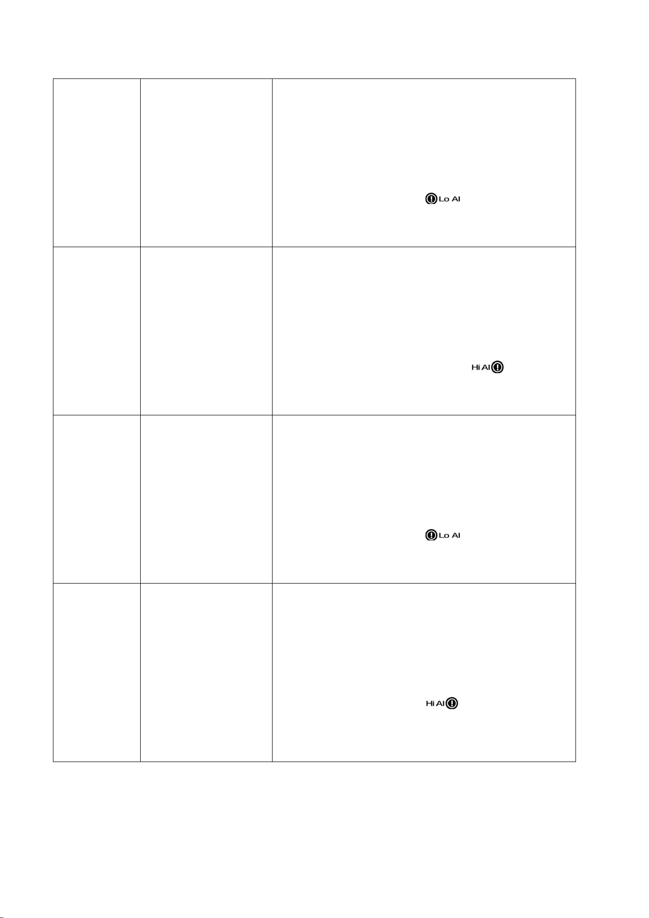
50
[SET]
Outdoor Dew Point
Low Alarm
· Press the WIND+ key or the PRESSURE- key to
increase or decrease the value. Long press to
increase or decrease quickly.
· Press the ALARM key to turn the alarm on or
off. The time area will display LOW ON/OFF. If
the alarm is on, an icon will be displayed
next to the parameter. If the alarm is off, the
icon will disappear.
[SET]
Outdoor Feels Like
High Alarm
·Press the WIND+ key or the PRESSURE- key to
increase or decrease the value. Long press to
increase or decrease quickly.
·Press the ALARM key to turn the alarm on or
off. The time area will display HI ON/OFF. If
the alarm is turned on, an icon will be
displayed next to the parameter. If the alarm is
turned off, the icon will disappear.
[SET]
Outdoor Feels Like
Low Alarm
· Press the WIND+ key or the PRESSURE- key to
increase or decrease the value. Long press to
increase or decrease quickly.
· Press the ALARM key to turn the alarm on or
off. The time area will display LOW ON/OFF. If
the alarm is on, an icon will be displayed
next to the parameter. If the alarm is off, the
icon will disappear.
[SET]
Outdoor Humidity
High Alarm
· Press the WIND+ key or the PRESSURE- key to
increase or decrease the value. Long press to
increase or decrease quickly.
· Press the ALARM key to turn the alarm on or
off. The time area will display HI ON/OFF. If
the alarm is on, an icon will be displayed
next to the parameter. If the alarm is off, the
icon will disappear.
51
[SET]
Outdoor Humidity
Low Alarm
· Press the WIND+ key or the PRESSURE- key to
increase or decrease the value. Long press to
increase or decrease quickly.
· Press the ALARM key to turn the alarm on or
off. The time area will display LOW ON/OFF. If
the alarm is on, an icon will be displayed
next to the parameter. If the alarm is off, the
icon will disappear.
[SET]
Indoor
Temperature High
Alarm
· Press the WIND+ key or the PRESSURE- key to
increase or decrease the value. Long press to
increase or decrease quickly.
· Press the ALARM key to turn the alarm on or
off. The time area will display HI ON/OFF. If
the alarm is on, an icon will be displayed
next to the parameter. If the alarm is off, the
icon will disappear.
[SET]
Indoor
Temperature Low
Alarm
· Press the WIND+ key or the PRESSURE- key to
increase or decrease the value. Long press to
increase or decrease quickly.
· Press the ALARM key to turn the alarm on or
off. The time area will display LOW ON/OFF. If
the alarm is on, an icon will be displayed
next to the parameter. If the alarm is off, the
icon will disappear.
[SET]
Indoor Humidity
High Alarm
· Press the WIND+ key or the PRESSURE- key to
increase or decrease the value. Long press to
increase or decrease quickly.
· Press the ALARM key to turn the alarm on or
off. The time area will display HI ON/OFF. If
the alarm is on, an icon will be displayed
next to the parameter. If the alarm is off, the
icon will disappear.
52
[SET]
Indoor Humidity
Low Alarm
· Press the WIND+ key or the PRESSURE- key to
increase or decrease the value. Long press to
increase or decrease quickly.
· Press the ALARM key to turn the alarm on or
off. The time area will display LOW ON/OFF. If
the alarm is on, an icon will be displayed
next to the parameter. If the alarm is off, the
icon will disappear.
[SET]
Gust High Alarm
· Press the WIND+ key or the PRESSURE- key to
increase or decrease the value. Long press to
increase or decrease quickly.
· Press the ALARM key to turn the alarm on or
off. The time area will display HI ON/OFF. If
the alarm is on, an icon will be displayed
next to the parameter. If the alarm is off, the
icon will disappear.
[SET]
Average Wind
Speed High Alarm
[SET]
Absolute Air
Pressure High
Alarm
· Press the WIND+ key or the PRESSURE- key to
increase or decrease the value. Long press to
increase or decrease quickly.
· Press the ALARM key to turn the alarm on or
off. The time area will display HI ON/OFF. If
the alarm is on, an icon will be displayed
next to the parameter. If the alarm is off, the
icon will disappear.
[SET]
Absolute Air
Pressure Low
Alarm
· Press the WIND+ key or the PRESSURE- key to
increase or decrease the value. Long press to
increase or decrease quickly.
· Press the ALARM key to turn the alarm on or
off. The time area will display LOW ON/OFF. If
the alarm is on, an icon will be displayed
next to the parameter. If the alarm is off, the
icon will disappear.

53
[SET]
Relative Air
Pressure High
Alarm
· Press the WIND+ key or the PRESSURE- key to
increase or decrease the value. Long press to
increase or decrease quickly.
· Press the ALARM key to turn the alarm on or
off. The time area will display HI ON/OFF. If
the alarm is on, an icon will be displayed
next to the parameter. If the alarm is off, the
icon will disappear.
[SET]
Relative Air
Pressure Low
Alarm
· Press the WIND+ key or the PRESSURE- key to
increase or decrease the value. Long press to
increase or decrease quickly.
· Press the ALARM key to turn the alarm on or
off. The time area will display LOW ON/OFF. If
the alarm is on, an icon will be displayed
next to the parameter. If the alarm is off, the
icon will disappear.
[SET]
Rainfall (Rate) High
Alarm
· Press the WIND+ key or the PRESSURE- key to
increase or decrease the value. Long press to
increase or decrease quickly.
· Press the ALARM key to turn the alarm on or
off. The time area will display HI ON/OFF. If
the alarm is on, an icon will be displayed
next to the parameter. If the alarm is off, the
icon will disappear.
[SET]
Rainfall (24H) High
Alarm
*[ALARM]+3 sec means press and hold the [ALARM] key for three seconds;
*[SET] means press the SET button.
*[ALARM] means press the [ALARM] button
NOTE: A tolerance of 0.9 °F (0.5°C) is set to prevent repeated temperature alarms.
For example, if a high temperature alarm is set to 26.7°C (80.0°F) and the alarm is
silenced, the alarm icon will continue to flash until the temperature drops below
26.7°C (80.0°F). At this point the alarm will reset and must rise above 26.7°C (80.0°F)
to activate again.
54
NOTE: To prevent repeated humidity alarms, the humidity alarm has a 4%
tolerance range.
For example, if the high alarm is set to 60% and the alarm is silenced, the alarm icon
will continue to flash until the humidity drops below 56%. At this point the alarm will
reset and must rise above 60% to become active again.
9.5. Calibration Mode
9.5.1. Calibration Settings
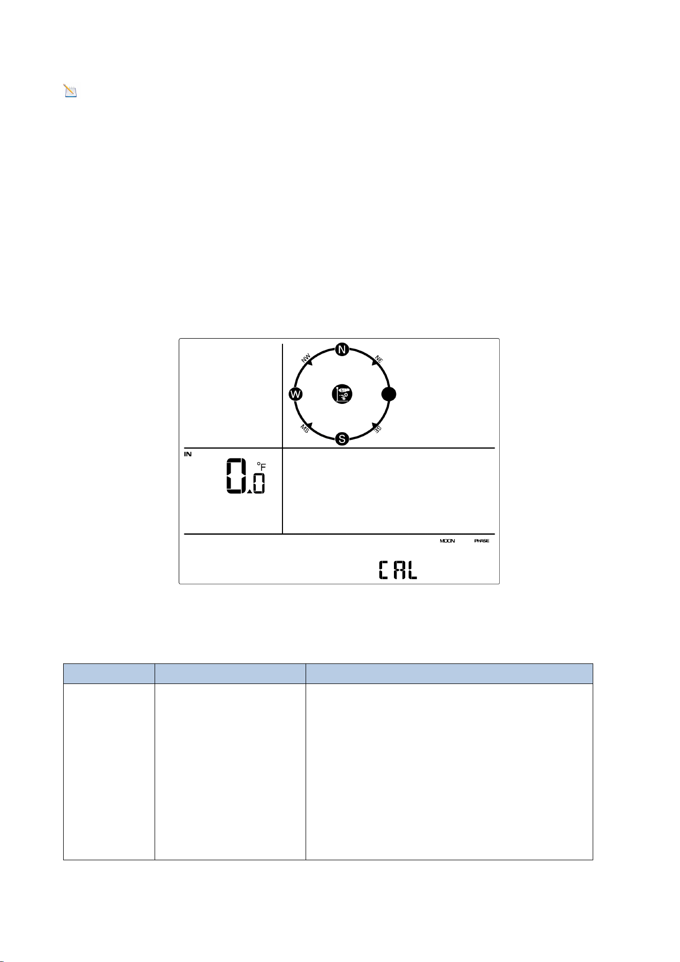
Press and hold the [TEMP] and [MAX/MIN] buttons at the same time for 3 seconds to
enter calibration mode. The CAL icon will be displayed.
To proceed to the next calibration setting, press (do not hold) the [SET] button.
Figure 24
The following chart summarizes the temperature calibration mode sequence and
commands.
Command
Mode
Settings
[TEMP] and
[MAX/MIN]
+3 sec
Enter the
temperature
calibration mode;
Indoor Temperature
Calibration
- Press the WIND+ key or PRESSURE- key
to increase or decrease the temperature
reading
- Press and hold the WIND+ key or
PRESSURE- key for three seconds to
quickly increase or decrease the
temperature reading.

55
- Press the ALARM key to reset the
current value.
[SET]
Indoor Humidity
Calibration
- Press the WIND+ key or PRESSURE- key
to increase or decrease the temperature
reading.
- Press and hold the WIND+ key or
PRESSURE- key for three seconds to
quickly increase or decrease the
temperature reading.
- Press the ALARM key to reset the
current value.
[SET]
Outdoor
Temperature
- Press the WIND+ key or PRESSURE- key
to increase or decrease the temperature
reading
- Press and hold the WIND+ key or
PRESSURE- key for three seconds to
quickly increase or decrease the
temperature reading.
- Press the ALARM key to reset the
current value.
[SET]
Outdoor Humidity
- Press the WIND+ key or PRESSURE- key
to increase or decrease the temperature
reading
- Press and hold the WIND+ key or
PRESSURE- key for three seconds to
quickly increase or decrease the
temperature reading.
- Press the ALARM key to reset the
current value.
[SET]
Absolute Pressure
- Press the WIND+ key or PRESSURE- key
to increase or decrease the temperature
reading
- Press and hold the WIND+ key or

56
PRESSURE- key for three seconds to
quickly increase or decrease the
temperature reading.
- Press the ALARM key to reset the
current value.
[SET]
Relative Pressure
- Press the WIND+ key or PRESSURE- key
to increase or decrease the temperature
reading
- Press and hold the WIND+ key or
PRESSURE- key for three seconds to
quickly increase or decrease the
temperature reading.
- Press the ALARM key to reset the
current value.
[SET]
Wind Speed
- Press the WIND+ key or PRESSURE- key
to increase or decrease the temperature
reading
- Press and hold the WIND+ key or
PRESSURE- key for three seconds to
quickly increase or decrease the
temperature reading.
- Press the ALARM key to reset the
current value.
[SET]
Rain Factor
- Press the WIND+ key or PRESSURE- key
to increase or decrease the temperature
reading
- Press and hold the WIND+ key or
PRESSURE- key for three seconds to
quickly increase or decrease the
temperature reading.
- Press the ALARM key to reset the
current value.
[LIGHT
Exit Temperature
If no operation is performed, the
57
SNOOZE]
Calibration Mode
calibration mode will time out and exit
after 30 seconds.
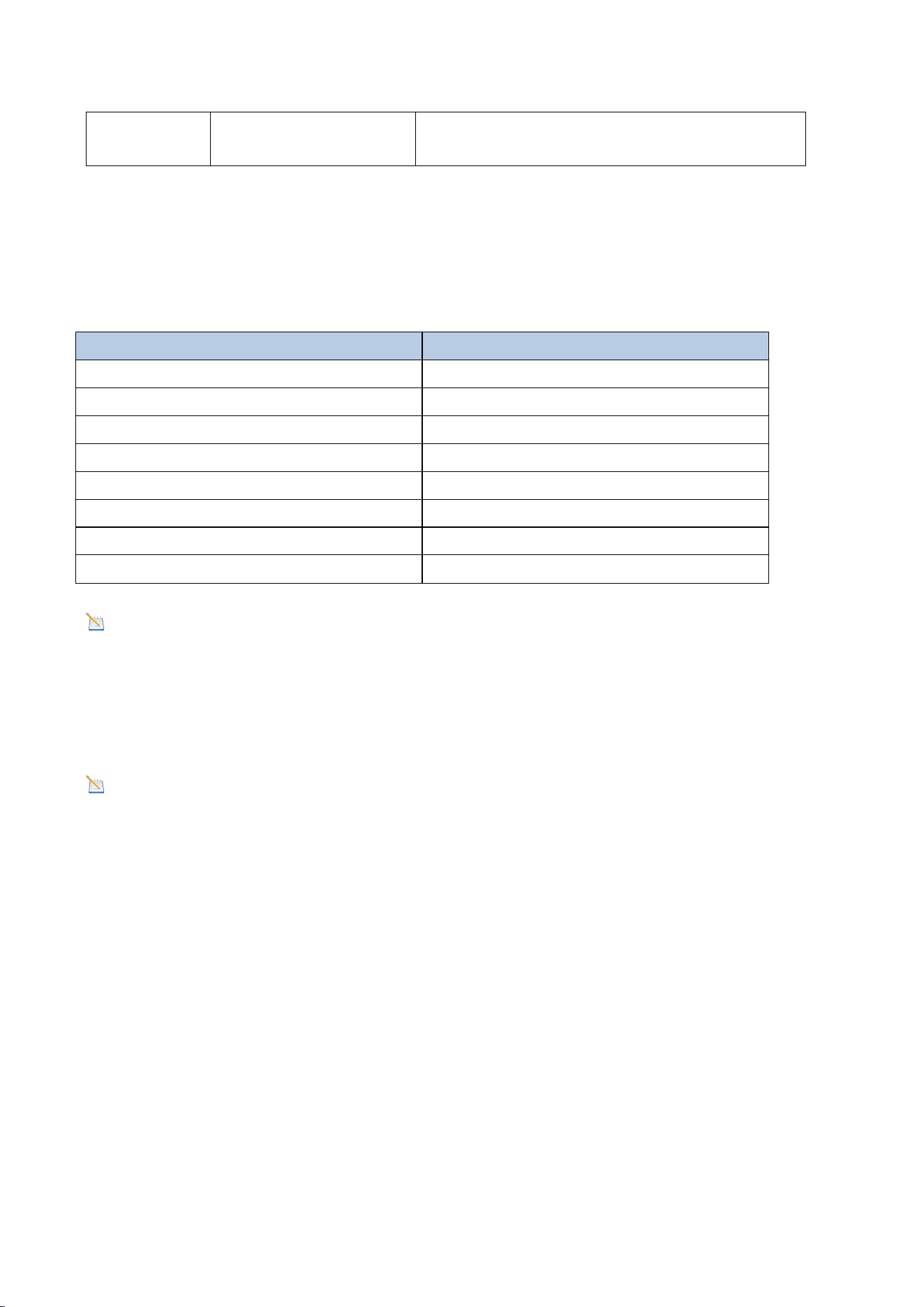
9.5.2. Calibration Ranges
The following chart summarizes the calibration ranges allowed for weather stations.
Parameter
Range
Indoor Temperature
± 9 °F (± 5 °C)
Outdoor Temperature
± 9 °F (± 5 °C)
Indoor Humidity
± 9 %
Outdoor Humidity
± 9 %
Absolute Pressure
± 0.27 inHg (± 6.8hpa)
Relative Pressure
± 0.27 inHg (± 6.8hpa)
Wind Speed
0.5-1.5
Rainfall
0.5.1.5
Note: The calibration range (0.5-1.5) for wind speed, rainfall, and sunlight are
coefficients, and the calibration formula is: Calibration value = Calibration
coefficient x Measured value.
9.5.3.Calibration Discussion
Note: The calibration value can only be adjusted on the display console, the
outdoor remote sensor always displays an uncalibrated or measured value.
The purpose of calibration is to fine-tune or correct any sensor errors associated with
the device's error range. Errors can result from electronic changes (e.g., temperature
sensors are resistive thermistors or RTDs, humidity sensors are capacitive devices),
mechanical changes or degradation (e.g., moving parts wear or sensor
contamination). Calibration is only useful when there is a known calibration source to
compare it to.
This section will discuss practices, procedures, and sources for sensor calibration to
minimize manufacturing and degradation errors. Do not compare data with results
obtained from sources such as the Internet, radio, television, or newspapers.
58
The purpose of a weather station is to measure the surrounding environmental
conditions, which vary greatly from location to location.
(1)
Temperature errors can occur when a sensor is placed too close to a heat source
(such as a building/structure, the ground, or trees).
To calibrate temperature, we recommend a mercury or red spirit (fluid) thermometer.
Bi-metal (dial) and digital thermometers (from other weather stations) are not a
good source and have their own margin of error.
Using a local weather station in your area is also an unreliable source due to changes
in location and timing (airport weather stations are only updated once per hour).
Place the sensor in a shaded, controlled environment next to the fluid thermometer,
and allow it to stabilize for 48 hours. Compare this temperature to the fluid
thermometer and adjust the console accordingly to match the reading.
(2)
Humidity is a difficult parameter to measure electronically and can drift over time
due to contamination. Additionally, location has an adverse effect on humidity
readings (such as installation over dirt versus a lawn).
Official stations recalibrate or replace humidity sensors on a yearly basis. Due to
manufacturing tolerances, the humidity is accurate to ± 5%. To improve this accuracy,
Parameter
Type of
Calibration
Default
Typical Calibration
Source
Temperature
Offset
Current Value
Red Spirit or Mercury
Thermometer (1)
Humidity
Offset
Current Value
Sling Psychrometer (2)
ABS Barometer
Offset
Current Value
Calibrated Laboratory-
Grade Barometer
REL Barometer
Offset
Current Value
Local Airport (3)
Wind Speed
Gain
1.0
Calibrated Laboratory-
Grade Wind Meter (4)
Rainfall
Gain
1.0
Sight Glass Rain Gauge
with an aperture of at
least 4”
(5)

59
the indoor and outdoor humidity can be calibrated using an accurate source, such as
a sling psychrometer.
Note: The measured humidity range is between 10% and 99%. Humidity cannot
be measured accurately outside of this range. Therefore, it is not possible to
calibrate humidity below 10% or above 99%.
(3)
The display console shows two different pressures: absolute pressure (measured
value) and relative pressure (corrected for sea level).
To compare air pressure conditions at different locations, meteorologists adjust air
pressure to sea level pressure. Because barometric pressure decreases with elevation,
the sea level corrected pressure (the pressure at your location if you are at sea level)
is usually higher than your measured pressure.
Thus, at an elevation of 1,000 feet (305 meters), the absolute barometric pressure
may be 28.62 inHg (969 mb), but the relative barometric pressure is 30.00 inHg (1016
mb).
The standard sea level pressure is 29.92 inHg (1013 mb). This is the average sea level
pressure for the entire world. A relative pressure measurement greater than 29.92
inHg (1013 mb) is considered high pressure, and a relative pressure measurement
less than 29.92 inHg is considered low pressure.
To determine the relative barometric pressure at your location, look for an official
reporting station near you (the Internet is the best source for real-time barometric
conditions, such as the Weather.com or Wunderground.com websites) and set your
weather station to match the official reporting station.
Note: The calibration settings will be saved to the display console until a factory
reset is performed. If the console location altitude is changed, the barometric
pressure will need to be recalibrated.
(4)
Wind speed is the most sensitive to installation constraints. The guideline for
properly installing a wind speed sensor is 4 x the distance of the tallest obstruction.
For example, if your house is 20’ tall and you mount the sensor on a 5’ pole:
Distance = 4 x (20 – 5)’ = 60’.
60
Many installations are not perfect and installing the weather station on a roof can be
difficult. Thus, you can calibrate for this error with a wind speed multiplier.
In addition to the installation challenges, wind cup bearings (moving parts) wear over
time.
Without a calibrated source, measuring wind speed can be challenging. We
recommend using a calibrated wind meter and a consistent, high-speed fan.
(5)
The rain collector is calibrated to the funnel diameter at the factory. The internal unit
of the rain collector records 0.01 inches of rainfall (called resolution) for each pour.
Accumulated rainfall can be compared to a sight glass rain gauge with an aperture of
at least 4 inches.
The rain cycle view is calculated as follows:
View
Period
Description
Example
1H
One hour delay from current
time
If the current time is 08:25, the 1-
hour rainfall refers to the rainfall
from 08:25 to 09:25.
24H
Same time from current time
to the day after
If the date is October 20 and the
time is 08:25, the 24-hour rainfall is
the amount of rainfall from 08:25
(10.20) to 08:25 (10.21).
Week
From the beginning of the
week to the current time
If the current time is 08:25 on
Thursday, the weekly rainfall refers
to the rainfall from 00:00 on this
Sunday to 08:25 on this Thursday.
Month
From the beginning of the
month to the current time
If the current time is 08:25 on
October 20, the monthly rainfall
refers to the rainfall from 00:00 on
October 1 to 08:25 on October 20.
Total
Total rainfall since the most
recent start
If the start time is now October 20,
2024, then the total rainfall is
October 20, 2024 to October 20,
2025.
Note: Debris and insects can collect in the dump unit (they can form spider
nests). Carefully remove the rain collector and check for debris in the dump unit
before calibrating.
Note: The rain gauge does not change with time.
61
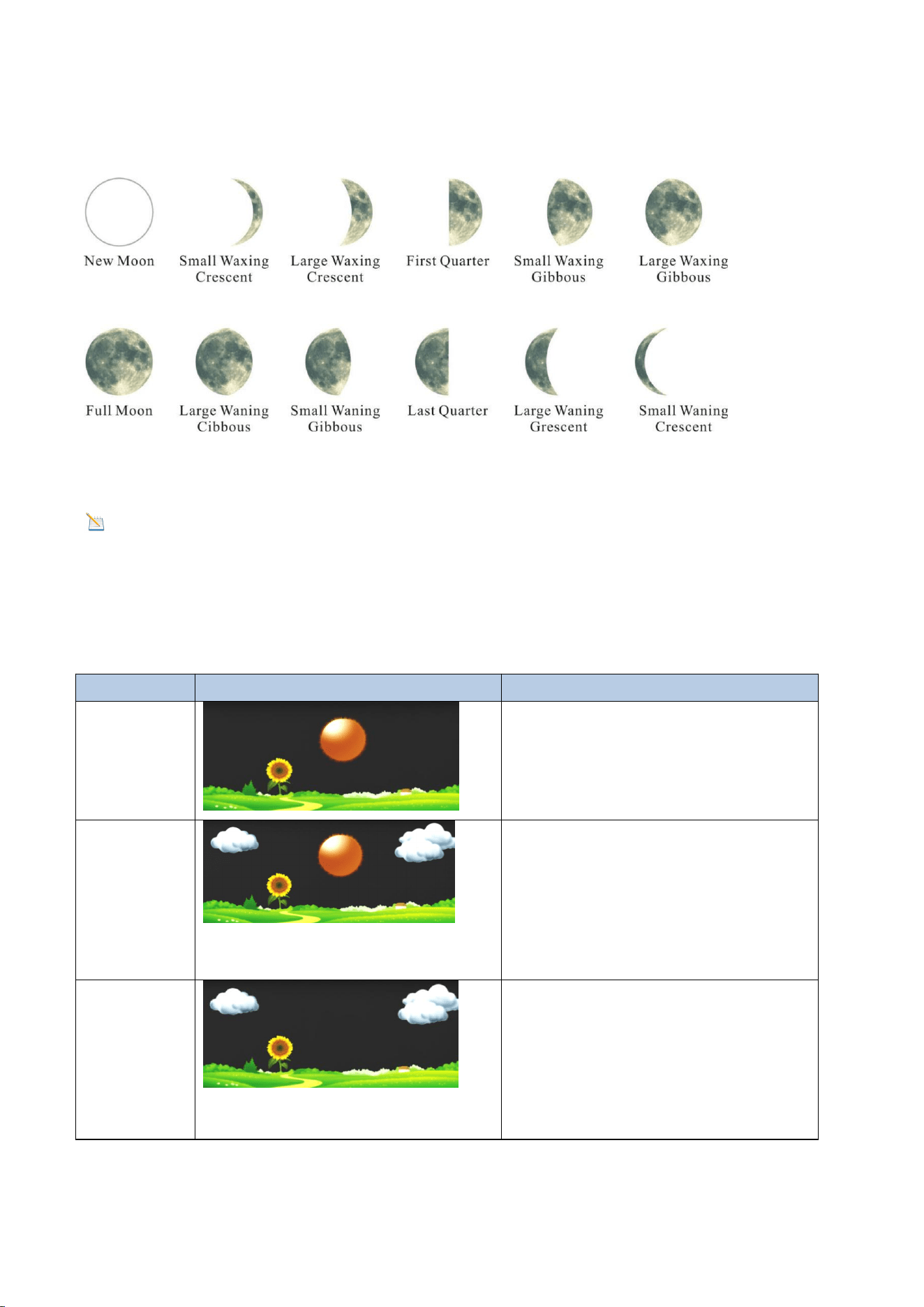
10. Moon Phase
The following moon phases are displayed according to the calendar date.
Figure 25
Note: The new moon does not show the phases of the moon.
11. Weather Forecasting
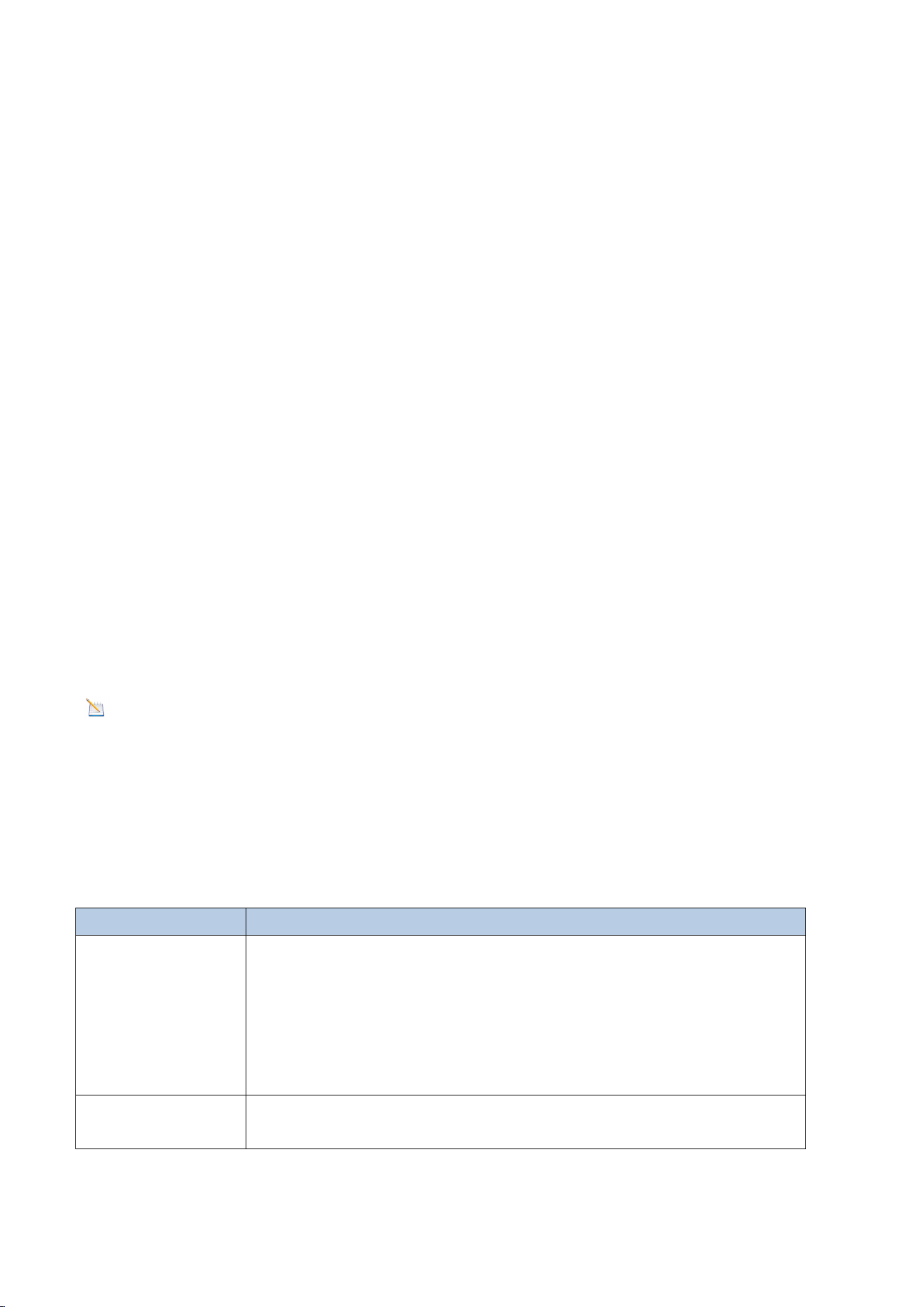
11.1. Weather Icon
Conditions
Icon
Description
Sunny
The pressure rises, and the
weather in the previous period
was less cloudy.
Partly
Cloudy
The pressure drops, and the
weather in the previous period
was sunny;
The pressure rises, and the
weather in the previous period
was cloudy.
Cloudy
The pressure drops, and the
weather in the previous period
was less cloudy;
The pressure rises, and the
weather in the previous period
was rainy.

62
Rainy
The air pressure dropped and the
weather was cloudy in the
previous period.
11.2. Weather Forecast Instructions and Limitations
Note: Weather forecasts or pressure trends are based on the rate of change of
air pressure. Generally speaking, as air pressure increases, the weather improves
(from partly cloudy to sunny ), and as air pressure decreases, the weather
deteriorates (from cloudy to rainy).
If the current conditions don't match the forecast icon, it is because the forecast is an
estimate or summary of how the weather is expected to change over the next 24-48
hours, which varies from place to place. Weather trends are only a tool for predicting
how the weather will change and should never be relied upon as an accurate method
of forecasting the weather. In most areas, these predictions are only 70% accurate,
so it's best to consult the National Weather Service for a more accurate weather
forecast.
11.3. Pressure Threshold
The pressure threshold (the rate of negative or positive pressure change that
indicates weather changes) can be adjusted between 2 hPa and 4 hPa (default is 2
hPa).
The lower the pressure threshold is set, the more sensitive it becomes to changes in
the weather forecast. Locations where pressure changes frequently require a higher
pressure threshold than those where the pressure is usually stagnant.
12. Backlight Operation
12.1. Connect the Power adapter
The display will remain on only when the power adapter is connected. The display
backlight has 3 levels of brightness.
When the backlight is on, short press the LIGHT SNOOZE button to switch between
the 3 levels of backlight.
63
When the backlight is off, press and hold the LIGHT SNOOZE button for 3 seconds
and the backlight will turn on permanently. The BL ON icon will be displayed in the
date area for 3 seconds.
To turn off the display backlight at any time, press and hold the LIGHT SNOOZE
button for two seconds. The BL OFF icon will appear in the date area for 3 seconds.
12.2. SNOOZE Mode
If the alarm sounds and you wish to silence the display, press the LIGHT SNOOZE key.
The alarm icon will continue to flash, the alarm will be silent for three minutes, and
the backlight will turn on.
Press LIGHT SNOOZE key to permanently exit Sleep mode.
12.3.Power Not Connected
When the display is not connected to the power adapter and is operated solely by
batteries, we do not recommend leaving the display backlight on for extended
periods; otherwise, the batteries will be depleted quickly.
Note: To save power, the backlight operates differently when using batteries.
If the display console is powered only by batteries and the backlight is off, briefly
press the LIGHT SNOOZE key once. The backlight will turn on for 3 seconds and will
turn off after 3 seconds of inactivity.
13. Glossary of Terms
Terms
Definition
Absolute
pressure
Absolute pressure is the measured atmospheric pressure and
is a function of altitude and, to a lesser extent, changes in
weather conditions.
Absolute air pressure is not corrected for sea level
conditions. See relative air pressure for details.
Relative pressure
The measured air pressure relative to your location or
environmental conditions.
64
HectoPascals
(hPa)
A unit of pressure measured in the SI (International System
of Units). Same as the millibar (1 hPa = 1 mbar).
Inches of
Mercury (inHg)
Pressure expressed in imperial units. (1 inHg = 33.86 mbar).
Dew point
Dew point refers to the temperature at which water vapor
condenses into water after cooling in air of a certain
humidity under constant air pressure. The condensed water
is called dew, and the dew point is a saturation temperature.
Dew point is related to relative humidity. A high relative
humidity means the dew point is closer to the current air
temperature. A relative humidity of 100% means the dew
point is equal to the current temperature and the water in
the air reaches maximum saturation. When the dew point
remains constant and the temperature rises, the relative
humidity decreases
Rain gauge
A rain gauge is a device that measures liquid precipitation
(rain) over a period of time, rather than solid precipitation
(snow, hail, or ice).
All digital rain gauges are self-emptying or self-dumping (also
called dumping rain gauges). The accuracy of a rain gauge
depends on the amount of rain that falls during each
emptying cycle.
Accuracy
Precision is defined as the ability of a measurement to match
the actual value of the quantity being measured.
Calibration
Calibration is the comparison between measurements made
by a device (standard) of known magnitude or correctness
with another device (instrument) in a manner as similar as
possible.
Range
Range is defined as the number and interval of measurable
values.
Resolution
Resolution is defined as the number of significant digits
(decimal digits) that can be reliably measured.
Wind vane
Wind direction refers to the direction the wind is blowing
from. For example, if the display shows the wind direction as
south, it means the wind is blowing from the south.
65
14. Specifications
14.1. Wireless Specifications
Wireless transmission
Specifications
Line of sight wireless sensor array RF
transmission (open air)
330 ft, 100 ft in most cases
Line of sight Wi-Fi RF transmission
(open air)
80 ft
Outdoor sensor update frequency
60 seconds
Sensor array RF frequency
433 MHz
Wi-Fi console RF frequency
2.4 GHz
14.2. Measurement Specifications
The table below provides the specifications of the measured parameters.
Measurement
Range
Accuracy
Resolution
Indoor
Temperature
0 to 60 °C
(32 to 140°F)
± 1 °C
(± 2°F)
0.1 °C(°F)
Outdoor
Temperature
-40 to 60 °C
(-40 to 140°F)
± 1 °C
(± 2°F)
0.1 °C(°F)
Indoor Humidity
10 to 99 %
± 5% (only
guaranteed
between 20
to 90%)
1%
Outdoor Humidity
10 to 99 %
± 5% (only
guaranteed
between 20
to 90%)
1%
Rainfall
0 to 9999mm
<15mm: ±1 mm,
15mm to
9999mm: ±7%
<1000mm
(0.3mm)
>1000mm
(1mm)
Wind Direction
0 - 360º
± 10º (16 point
compass)
± 1º (16 point
compass)
Wind Speed
0 to 50 m/s
2 m/s ~10
m/s:±0.3m/s
, 10m/s ~50
m/s: ±10%
(whichever
0.1 m/s
66
is greater)
Barometric
Pressure
300 to 1100
hpa
± 3 hpa
0.1 hpa
14.3. Power Consumption
Display Console
3 x AAA 1.5V alkaline or lithium
batteries (not included)
Integrated Outdoor Sensor:
3xAA alkaline or lithium batteries (not
included) provide backup power when
solar power is limited.
Note: Solar panels can charge the
batteries.
Power Adapter
5V ~ 1000mA (included)
Battery Life
If the base station signal reception is
good, the transmitter battery can last at
least 3 months.
If the base station reception signal is
intermittent, the transmitter battery
life may be reduced.
We recommend using lithium batteries
for the transmitter in cold climates
below -20°C (-4°F).
15. Maintenance
(1)We recommend cleaning the rain gauge once every 3 months. Twist the funnel
clockwise and lift it vertically to expose the rain gauge assembly (see the image
below). Then wipe the internal rain gauge assembly with a damp cloth to remove any
dirt, debris, or insects. If insect infestation is a concern, you can lightly spray the
array with an insecticide.
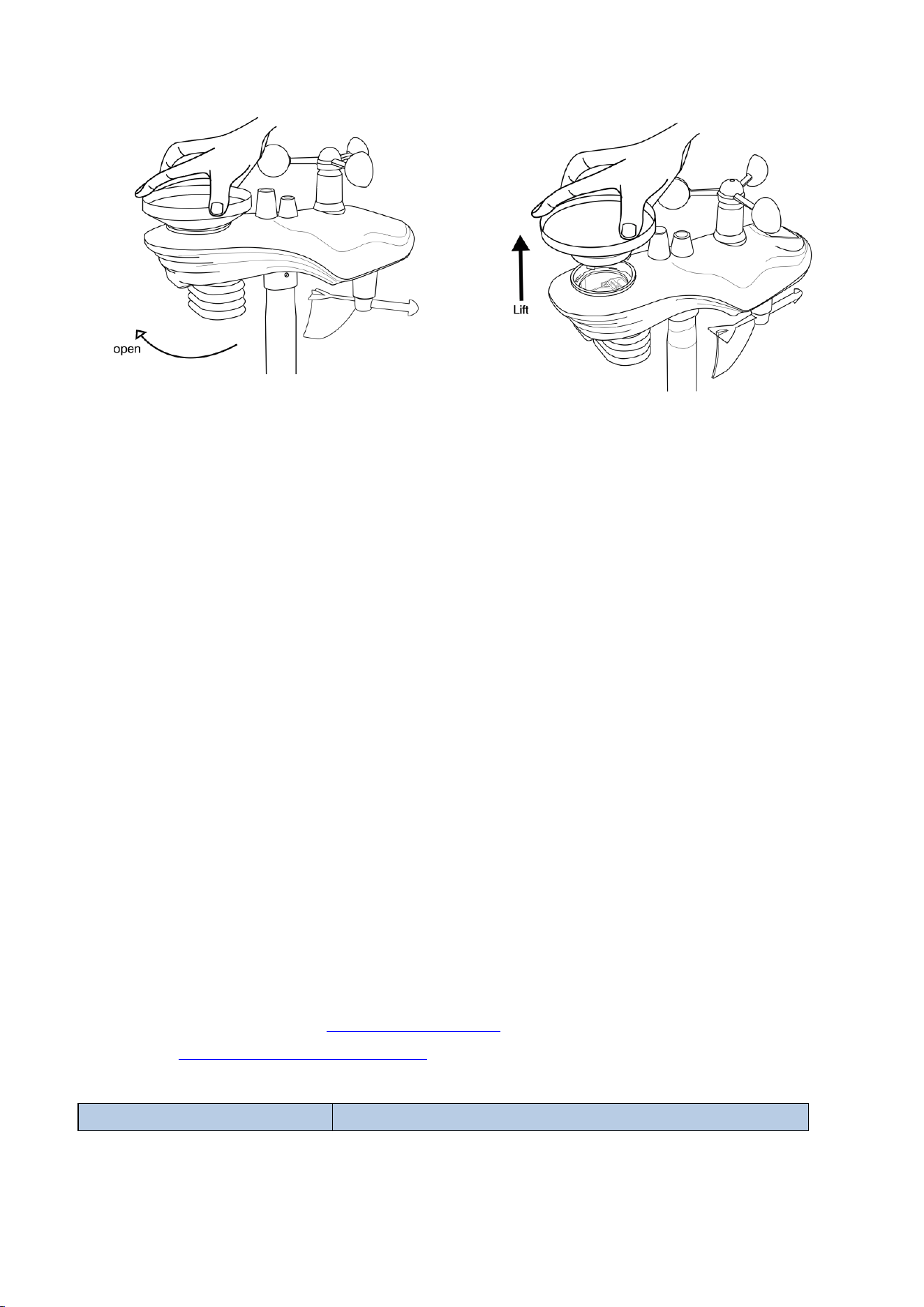
67
Figure 26
(2) Clean the solar panel with a damp cloth every 3 months. Replace the battery
every 3 months. If left for too long, the battery may leak due to environmental
factors. In harsh environments, check the battery every 3 months (when cleaning the
solar panel).
(3) When replacing the battery, apply anti-corrosion compound to the battery
terminals, which is available on Amazon and most hardware stores.
(4) In snowy conditions, spray the top of the weather station with anti-icing silicone
spray to prevent snow accumulation.
(5) Over time, the smoothness of the rain gauge funnel surface will degrade due to
dirt, debris. We recommend spraying Teflon spray on the rain gauge funnel and coil
filter to reduce the surface tension of the water.
16. Troubleshooting Guide
If your question is not answered here, you can contact us by E-mail, Phone, and on
our Website:
Customer Support Phone and Website:
Website:https://www.sainlogic.com/
Customer Support Phone:+1 (888) 513-9823 (Mon-Fri:10 a.m. - 6 p.m. EST)
Problem
Solution

68
The wireless remote
control is not reporting to
the console.
The display console has
dotted lines; dashes (--.-).
If any sensor communication is lost, dashes (--.-)
will appear on the screen. To reacquire the signal,
press and hold the TEMP button for 3 seconds,
select the lost sensor, and the remote search icon
will display continuously.
Press the reset button on the outdoor unit again to
pair.
When the signal is reacquired, the remote search
icon will turn off and the current value will be
displayed.
When the signal is reacquired, the remote search
icon will turn off and the current value will be
displayed.
You can also reset the transmitter.
After the transmitter is powered on, if the indicator
light blinks every 60 seconds it means the outdoor
unit is working properly.
After the transmitter is powered on and working pr
operly, the display has to be re-plugged in to re-
receive the transmitter signal. It usually takes 1-
3 minutes to receive the data, do not operate the k
eys or power off until the transmitter data is receiv
ed.
If this still does not help, please follow the steps
below to reconnect the transmitter and display to
troubleshoot poor connections.
1. Remove the batteries of the transmitter and the
display.
2. Unplug the display from the power supply.
3. Put batteries in the transmitter.
4. Plug in the power of the display.
5. Put the batteries in the display after the display
lights up and the data show dashes.
Also, you can replace the batteries in the
69
transmitter with new ones.
In most cases, the maximum line-of-sight
communication distance is 100 meters (330 feet)
and 30 meters (100 feet), move the sensor
assembly closer to the display console.
If the sensor assembly is too close (less than 1.5
meters/5 feet), move the sensor assembly away
from the display console.
Install a new set of batteries for the remote sensor.
In cold weather environments, install lithium
batteries.
Make sure the remote sensor is not transmitting
through solid metal (as an RF shield) or earth
barriers (under a mountain).
Keep the display console away from devices that
generate electrical noise, such as computers,
televisions, and other wireless transmitters or
receivers.
Display console has weak
contrast
Replace the console batteries with a new set of
batteries.
Indoor temperature and
humidity data is
incorrect/the display
shows incomplete data
You can reset the display console to factory
defaults by pressing and holding the PRESSURE- key
for at least three seconds while plugging in the
power supply. Then unplug the display and plug it
back in. (Remove the batteries before doing this).
If any data is not displayed, press and hold the
WIND+ key for three seconds until a click is heard
and all data is displayed as dashed lines.
The display will reacquire the signal from the
transmitter. Once the signal is reacquired, all data
will be displayed.
Display brightness is very
dim
Adjust the backlight (refer to Section 12).
If the brightness cannot be adjusted, it means that
the power adapter or the display interface has a

70
poor contact problem.
Weather forecast is
inaccurate
The weather icon is a weather forecast, an estimate
or summary of weather changes in the next 24 to
48 hours, which varies from place to place. This
trend is only a tool to predict how the weather will
change, and it should never be used as an accurate
method to predict the weather.
If you are just starting to use the weather station,
wait for about a week for the pressure sensor to
slowly adapt to the environment, and then adjust
the data and weather forecast.
After using it for a while, if the weather forecast is
still inaccurate, you can follow the steps in the
manual to manually set the weather icon to show
the actual weather.
Rainfall display is
incorrect/zero
Please check and verify the following points when
you find you rainfall is not working or inaccurate:
1.Make sure that the level bubble is seated in the
small black circle in the installation. Sloping
installation might cause incorrect reading or even
not working.
2. Shake the sensor array back and forth. After
hearing the click sound inside the sensor array,
observe whether the rainfall reading in the console
changes.
3. Check whether the funnel in the rain collector
was blocked by tree leaves or debris. Remove the
rain collector to check whether the rain tip was
blocked by insects or debris.
4. Check whether different rainfall histories are
correct. Check the Quick Mode part in the
instruction manual to know how to get rainfall
histories in different periods.
5. An example on how rainfall histories for different
71
Note: One transmitter can connect to multiple displays of the same model, but a
single display cannot be connected to multiple transmitters simultaneously.
Note: Please carefully verify that the model is consistent before making a
purchase. If you have any questions before purchase, please consult the after-sales
service in advance.
17.Disclaimer
Please protect the environment by returning used batteries to an authorized
recycling station. Electrical and electronic waste contains hazardous substances.
Disposal of e-waste in the natural environment and/or in unauthorized locations can
harm the environment.
Reading the user manual is strongly recommended. The manufacturer and supplier
cannot be held responsible for any incorrect readings or consequences resulting from
failure to read the manual carefully.
periods are calculated.
Presume that the current time is 08:42 22rd Sept.
2023
Rainfall Hour: 08:42-09:42
Rainfall Day: 08:42 on September22 to
08:42 on September 23
Rainfall Week: 00:00 Sunday to 08:42 today
Rainfall Month: 00:00 1st Sept. to 08:42 today
Rainfall Total: Total rainfall amount from the latest
powering on
6. How to verify the rainfall accuracy
A:Use a bottle containing 500g or 500ml of water.
B:Drip water slowly into the rain collector. DO
NOT POUR WATER QUICKLY.
C. Observe the rainfall reading of the console after
the water is completely dripped out. It should be
5.46cm +/-5%. (5.46cm=54.6mm)
7. The rain gauge could not measure rainfall below
0.3mm due to limited resolution.

72
This product is intended for home use only and is not intended for medical purposes
or public safety information. This product is not a toy and should be kept out of the
reach of children.
We assume no liability for accidental, consequential, punitive or other similar
damages related to operation or malfunction.
18. Warranty Information
Sainlogic provides a 1-year limited warranty against manufacturing defects in
materials and workmanship on this product.
This limited warranty tekes effect on the date of original purchase and is valid only
for the product purchased and only for the original purchaser of this product. To
obtain warranty service, the purchaser must contact Sainlogic to determine the
problem and service procedure.
Warranty service can only be performed by Sainlogic. The original dated bill of sale
must be presented to Sainlogic upon request as proof of purchase.
Sainlogic's warranty covers all defects in materials and workmanship except:
(1) Damage caused by accident, unreasonable use or neglect (lack of reasonable and
necessary maintenance);
(2) Damage caused by failure to follow the instructions in the user's manual;
(3) Damage caused by self-repair or alteration;
(4) Equipment not intended for personal use;
(5) Applications and uses of this product that do not correspond to the intended use;
(6) The product is unable to receive signals due to any source of interference or
metal obstruction;
If you need to register or apply for a warranty, please get in touch with us through
Customer Support.
Website:https://www.sainlogic.com/
Customer Support Phone:+1 (888) 513-9823 (Mon-Fri:10 a.m. - 6 p.m. EST)

73
19. FCC Statement
1. This device complies with Part 15 of the FCC Rules.Operation is subject to the
following two conditions:
(1) This device may not cause harmful interference, and
(2) This device must accept any interference received, including interference that
may cause undesired operation.
2. Changes or modifications not expressly approved by the party responsible for
compliance could void the user’s authority to operate the equipment.
NOTE: This equipment has been tested and found to comply with the limits for a
Class B digital device, pursuant to Part 15 of the FCC Rules. These limits are designed
to provide reasonable protection against harmful interference in a residential
installation.
This equipment generates, uses and can radiate radio frequency energy and, if not
installed and used in accordance with the instructions, may cause harmful
interference to radio communications.
However, there is no guarantee that interference will not occur in a particular
installation. If this equipment does cause harmful interference to radio or television
reception, which can be determined by turning the equipment off and on, the user is
encouraged to try to correct the interference by one or more of the following
measures:
Reorient or relocate the receiving antenna.
Increase the separation between the equipment and receiver.
Connect the equipment into an outlet on a circuit different from that to which
the receiver is connected.
Consult the dealer or an experienced radio/TV technician for help.
FCC ID: 2BP5V-8SA8P