
1
Sainlogic SA1 Weather Station User Manual
Content
1.Getting Started ...................................................................................................3
1.1. Part Lists ....................................................................................................3
2. Weather Station Power On ............................................................................... 3
2.1. Thermo-hygrometer Sensor ......................................................................3
2.2. Display Console ......................................................................................... 4
2.3. Best Practices for Wireless Communication ............................................. 5
2.4. Button Operation ......................................................................................6
3. Display Console Features .................................................................................. 7
3.1. Quick SET Mode ........................................................................................ 7
3.2. Set (Program) Mode ..................................................................................8
3.3. Min/Max Mode .........................................................................................9
3.4. Alarm Mode ............................................................................................ 10
3.4.1. View High/Low Alarms ....................................................................10
3.4.2. Setting High/Low Alarms ................................................................ 10
3.4.3. Alarm Triggered .............................................................................. 16
3.4.4. Button Beeper ON/OFF ...................................................................16
3.5. Snooze Mode .......................................................................................... 16
3.6. Backlight Mode ....................................................................................... 17
4. Display connected to WiFi ...............................................................................17
4.1. Real-time Network Monitoring ............................................................... 17
4.2. APP Download .........................................................................................17
4.3. APP Account Register and Login ............................................................. 18
4.3.1. Registering Process ......................................................................... 18
4.3.2. Login Process .................................................................................. 19
4.4. MAC Address ...........................................................................................19
4.5. IP Address ............................................................................................... 20
5.Connecting Steps ............................................................................................. 20
5.1. Bluetooth Distribution Network Mode ................................................... 21
5.2. WiFi Distribution Network Mode ............................................................26
5.3. Web page distribution network mode ....................................................31
6.Firmware Upgrade ........................................................................................... 36
7. Sensor Search Mode....................................................................................... 37
8. Battery Icon ................................................................................................... 37
9. Rate of Change Icon.........................................................................................37
10. Calibration Mode...........................................................................................38

2
10.1. Temperature Calibration .......................................................................39
10.2. Humidity Calibration ............................................................................. 40
10.3. Pressure Calibration ..............................................................................42
11. Factory Default Reset ....................................................................................43
12. Other Console Features ................................................................................ 43
12.1. Weather Forecasting .............................................................................43
12.2. Weather Icons .......................................................................................44
13. Moon Phase .................................................................................................. 45
14. Specifications ................................................................................................ 45
14.1. Wireless Specifications ......................................................................... 45
14.2. Measurement Specifications ................................................................ 45
14.3. Power Consumption ............................................................................. 46
15. Troubleshooting Guide ..................................................................................46
16. Disclaimer ......................................................................................................48
17. Warranty Information ................................................................................... 49
18. FCC Statement ...............................................................................................50
3
1.Getting Started
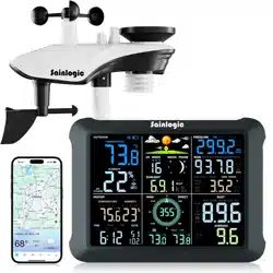
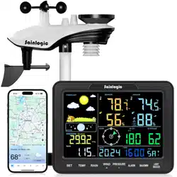
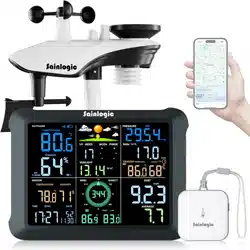
The weather station consists of a display console (receiver), and one
thermo-hygrometer Sensor.
Note: Power up the sensors with battery first, and the
Display Console with adapter second, don’t press any button until all data is
received.
1.1. Part Lists
QTY
Item
1
Display Console
Frame Dimensions : 8.5x6.2x1inch
(215.9x157.5x25.4mm)
LCD Dimensions :
6.55x4.85inch(166.37x123.19mm)
1
Thermo-hygrometer Sensor
1
Manual
1
Power Adapter
2. Weather Station Power On
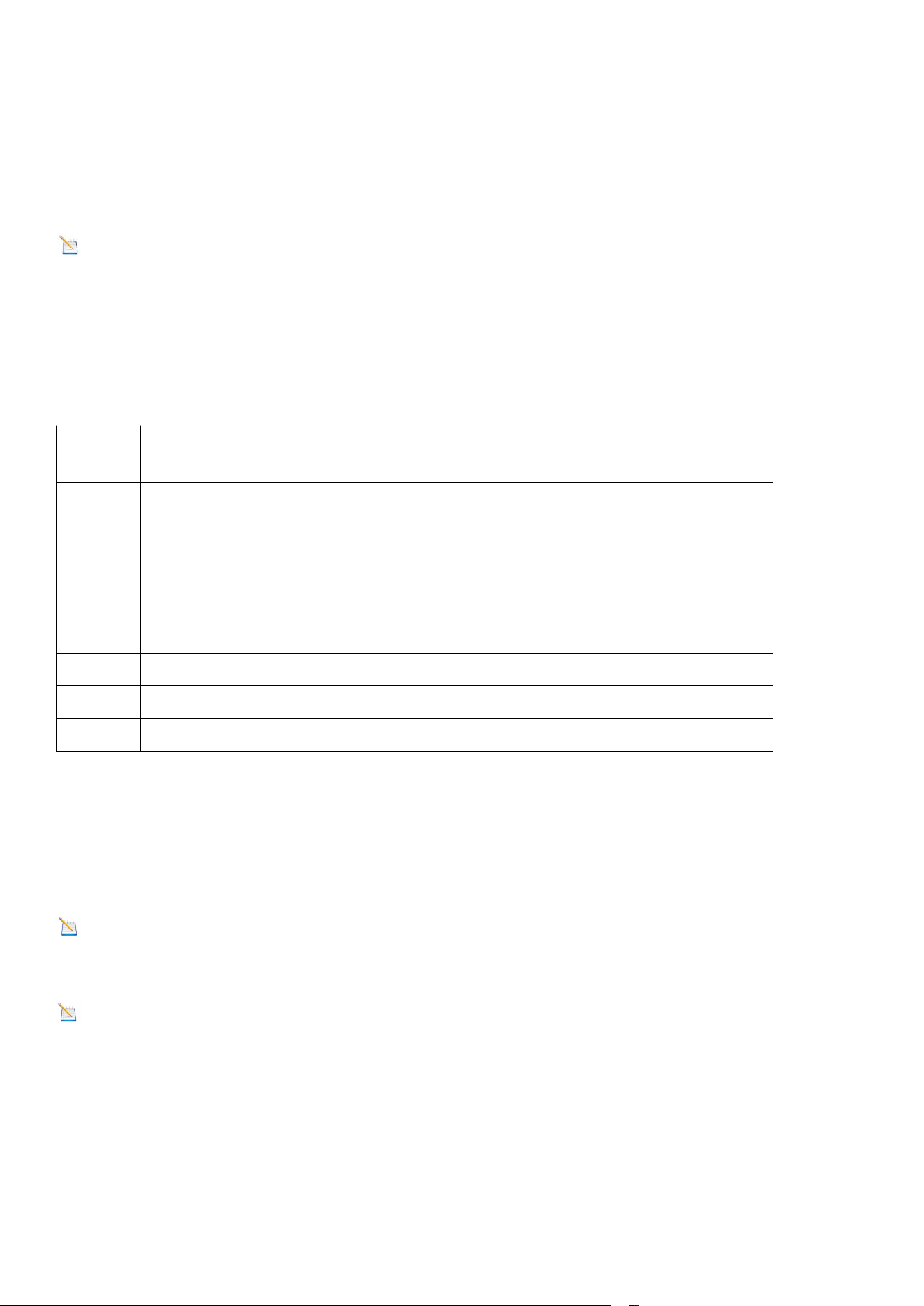
2.1. Thermo-hygrometer Sensor
Note: To avoid permanent damage, please take note of the battery polarity
before inserting the batteries.
Note: Lithium batteries are recommended for cold weather environments.
1. Open the battery compartment, as shown below. Insert three fresh AAA
batteries (with the negative terminal of the battery in contact with each spring).
4
Figure 1
2. The LED shown in above image will light up (visible through the plastic).
3. It is recommended you mount the thermo-hygrometer sensor outside in a
shaded area. A north facing wall is preferred because it is in the shade
most of the day. Direct sunlight and radiant heat sources will result
in inaccurate temperature readings. Although the sensor is not waterproof, it
is best to mount in a well protected area, such as under an eve.
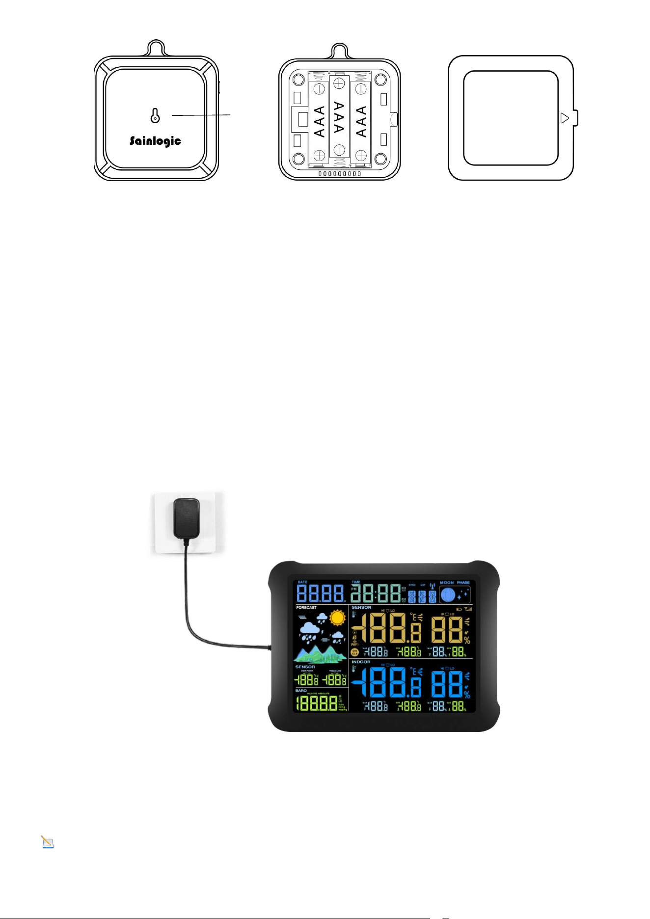
2.2. Display Console
1. Power on with adapter to keep the backlight on. The battery is a back-up
option, saving console settings when powered off from adaptor.
Figure 2
Note: Power the console with an adapter first, not the
batteries, otherwise the backlight will not light on constantly.
LED
5
Note
:
It is recommended that the power adapter be plugged in all the time to
minimize display battery consumption and extend battery life. If you use battery
power, it will not stay on constantly and will probably only last about 2 hours.
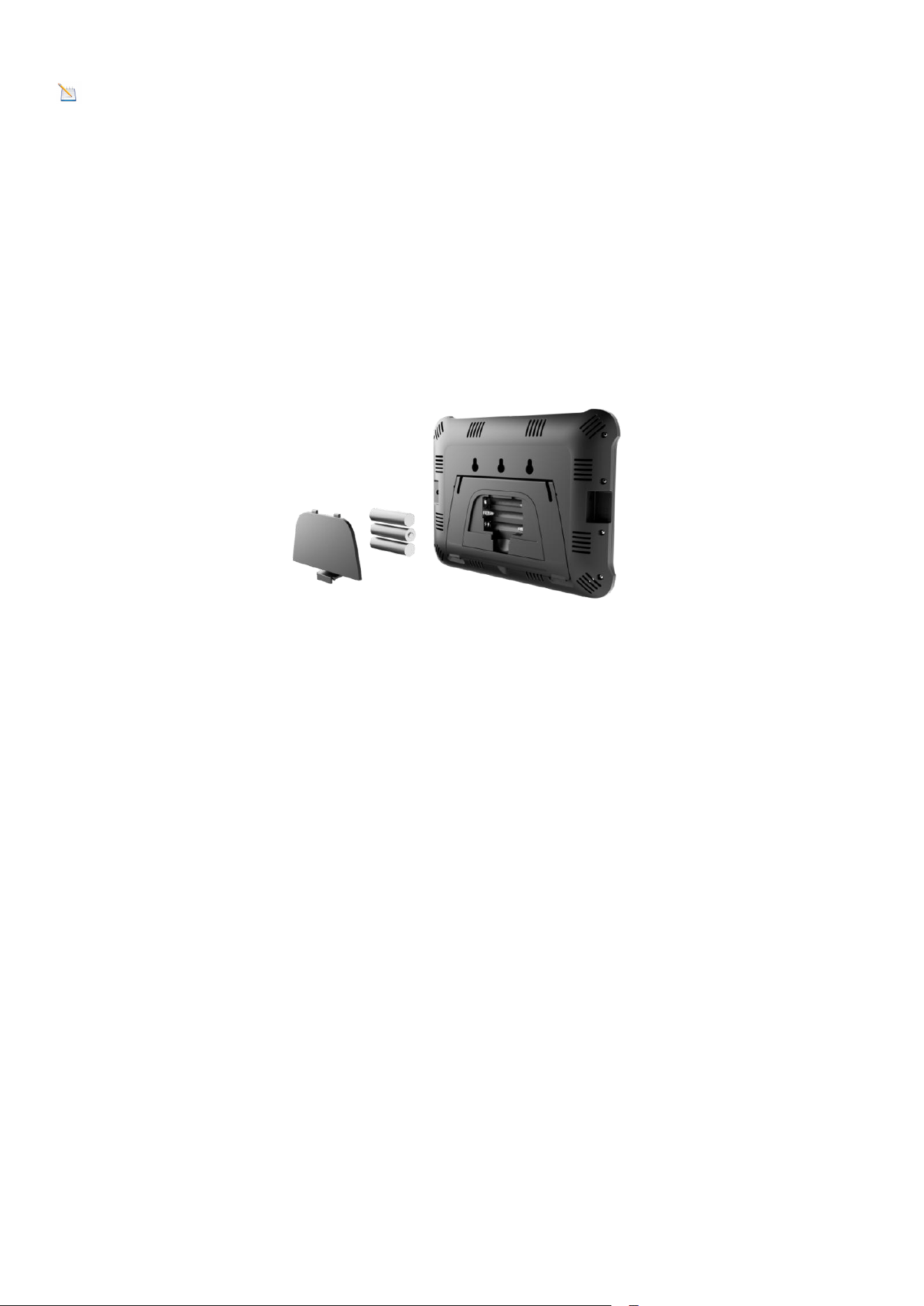
2. Remove the battery door on the back of the display, Install 3xAAA
batteries and close the door, place on the desk or mount on
the wall.
Figure 3
2.3. Best Practices for Wireless Communication
Wireless communication is susceptible to interference, distance, walls, and
metal barriers. We recommend the following best practices for trouble-free
wireless communication.
1. Electro-Magnetic Interference (EMI): Keep the console several feet away
from computer monitors and TVs.
2. Radio Frequency Interference (RFI): If you have other 433 MHz devices and
communication is intermittent, try turning off these other devices for
troubleshooting purposes. You may need to relocate the transmitters or
receivers to avoid intermittent communication.
3. Line of Sight Rating: This device is rated at 300 feet line of sight (no
interference, barriers, or walls), but typically you will get 100 feet maximum.
[This is under most real-world installations, which include passing through
barriers or walls].
6
4. Metal Barriers: Radio frequency will not pass through metal barriers, such as
aluminum siding. If you have metal siding, align the remote and console through
a window to get a clear line of sight.
The following is a table of reception loss, versus the transmission medium. Each
“wall” or obstruction decreases the transmission range by the factor shown
below:
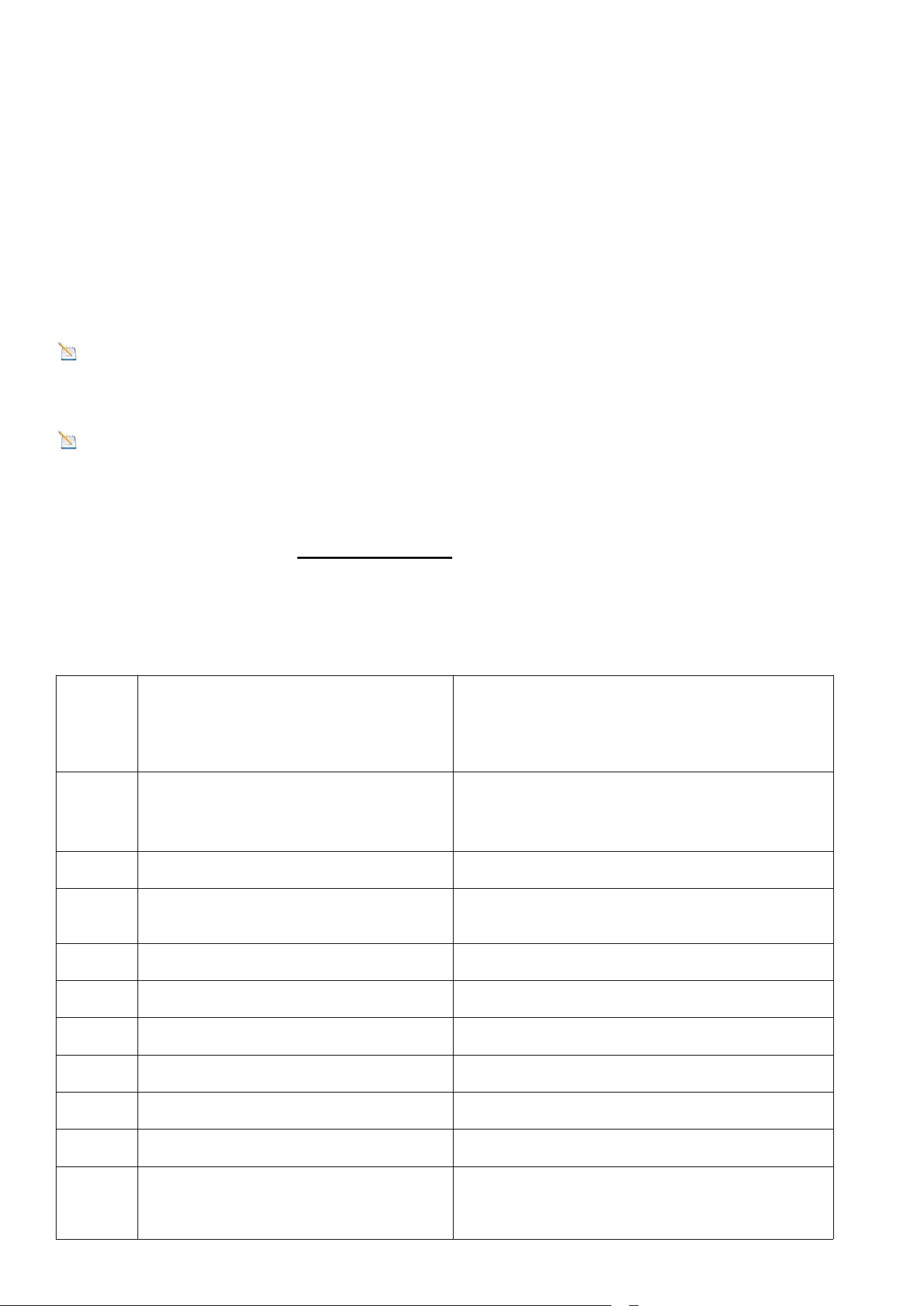
2.4. Button Operation
Figure 4
There are the following 5 keys on the right side of the console (from top to
bottom), which are used to set the display functions by short press, long press
or double click.
Note: SET/MODE is the same key and has the same function.
Medium
Radio Frequency (RF) signal
strength reduction
Glass (untreated)
5-15%
Plastic
10-15%
Wood
10-40%
Brick
10-40%
Concrete
40-80%
Metal
90-100%
Key
Description

7
3. Display Console Features
3.1. Quick SET Mode
Note: The console has five keys for easy operation:
MAX/MIN- key, SET key, ALARM key, CHANNEL/+ and SNOOZE
key.
Note: To exit the Quick SET Mode at any time, press the SNOOZE button of
the display console.
While in Normal Mode, press (do not hold) the SET key
repeatedly to enter into below 2 modes:
SNOOZE
1. In normal mode, short press to toggle between 3
levels of brightness.
2. In any setting mode, short press to return to normal
mode.
CHANNEL/+
1. In normal mode, press and hold the SET key at the
same time for 5 seconds to enter the temperature
calibration mode; double-click to display the MAC
address.
2. In any setting mode, short press to increase the
value; long press to increase the value quickly.
SET/MODE
1. In normal mode, short press to enter fast display
mode; long press to enter setting mode
2. In any setting mode, short press to skip any step to
the next step.
ALARM
1. In normal mode, short press to view alarm
parameters; long press to set alarm mode.
2. In calibration mode, short press to reset the
calibration value.
MAX/MIN/-
1. In normal mode, short press to switch to view the
maximum and minimum values; long press to enter the
network mode; double-click to display the IP address.
2. In any setting mode, short press to reduce the
value; long press to quickly reduce the value.
8
1. Date and Year.
Press the [+] or [-] key to toggle between year and date. Day of the week and
seconds can also be switched.
2. Absolute Pressure and Relative Pressure.
Press the [+] or [-] key to toggle between absolute pressure and relative
pressure.
3.2. Set (Program) Mode
Note: In the Set mode, press the [+] or [-] key to change or scroll the value.
Hold the [+] or [-] key for three seconds to increase/decrease rapidly.
Note: To exit the Set mode at anytime, press the SNOOZE button of the
display console.
While in Normal Mode, press and hold the SET key for at least five seconds to
enter the Set Mode. The first setting will begin flashing. You can press the SET
key again to skip any step, as defined below.
Short Press SET Key to skip
entering into the following
features and flash.
Press the [+] or [-] key to set up the
following features.
1
Time SYNC (default: ON)
Synchronize the device with the
time and date via WiFi
2
DST (default: ON)
Turn DST on or off
3
12/24 Hour Format
12 hour or 24 Hour Format
4
Hour
Hour value up or down
5
Minute
Minute value up or down
6
Date Format
M-D or D-M
7
Month
Calendar month
8
Day
Calendar day
9
Year
Calendar year
10
Max/Min Clearing
ON (Clears 24h) or

9
OFF(Manually)
11
Temperature Units
°F or °C
12
Barometric Pressure Units
mmhg, inHg or hPa
13
Pressure threshold setting
(default value: 2 levels)
change the pressure
threshold from 2 hPa to 4 hPa
14
Weather Forecast Icon
sunny, partly cloudy, cloudy, or
rainy
Note:The weather icon does
not change immediately, wait 4
hours for it to change.
15
Location area
(default value: Northern
Hemisphere)
NOR or SOU
Note: Pressure Threshold
The pressure threshold (the rate of negative or positive pressure change that
indicates weather changes) can be adjusted between 2 hPa and 4 hPa (default is
2 hPa).
The lower the pressure threshold is set, the more sensitive it is to changes in the
weather forecast. Locations where the pressure changes frequently require a
higher pressure threshold than locations where the pressure is usually stagnant.
3.3. Min/Max Mode
In normal mode, press (do not hold) the ALARM key, the MAX icon will be
displayed. Press the MAX/MIN/- key to view pressure (ABS or REL)
and dew point(outdoor) max value.
Press SET key to switch the Relative pressure and Absolute pressure.
Press the MAX/MIN/- key for three seconds to clear the
maximum values of pressure, temperature and humidity. The maximum values
will now display the current values.

10
Press the MAX/MIN/- key to view pressure (ABS or REL) and dew
point(outdoor) min value.
Press SET key to switch the Relative pressure and Absolute pressure.
Press the MAX/MIN/- key for three seconds to clear the
maximum values of pressure, temperature and humidity. The minimum values
will now display the current values.
Press the SNOOZE key to exit the min/max checking and
cleaning mode, return to normal display mode.
3.4. Alarm Mode
The weather station includes time, indoor/sensor temperature and humidity ,
dew point alarm and pressure (ABS and REL) alarm.
3.4.1. View High/Low Alarms
To view the current alarm settings, press the ALARM key once to enter the
alarm mode. Alarm 1 and other HI alarm parameters are displayed.
Press the ALARM key again to view the LOW alarm. Alarm 1 and other Low
alarm parameters are displayed.
Press the SET key to switch to the Alarm 2 section. Press the ALARM key
again to switch between high and low alarm parameters.
Press the SNOOZE key at any time to return to the normal mode.
3.4.2. Setting High/Low Alarms
Press and hold the ALARM key once to enter the alarm mode.
Press and hold the SET key for three seconds. The first alarm parameter will
begin flashing.
To save the alarm setting and proceed to the next alarm
parameter, Press (do not hold) the SET key.
11
To adjust the alarm parameter, press the [+] or [-] key to
increase or decrease the alarm setting slowly, or press and hold the [+] or [-]
key for three seconds to increase or decrease the alarm setting rapidly.
Press the ALARM key to turn on (the alarm icon will appear
) and off the
alarm.
Press the SNOOZE key twice at any time to return to the
normal mode.
The following diagrams summarize the sequence and instructions for setting
alarms.
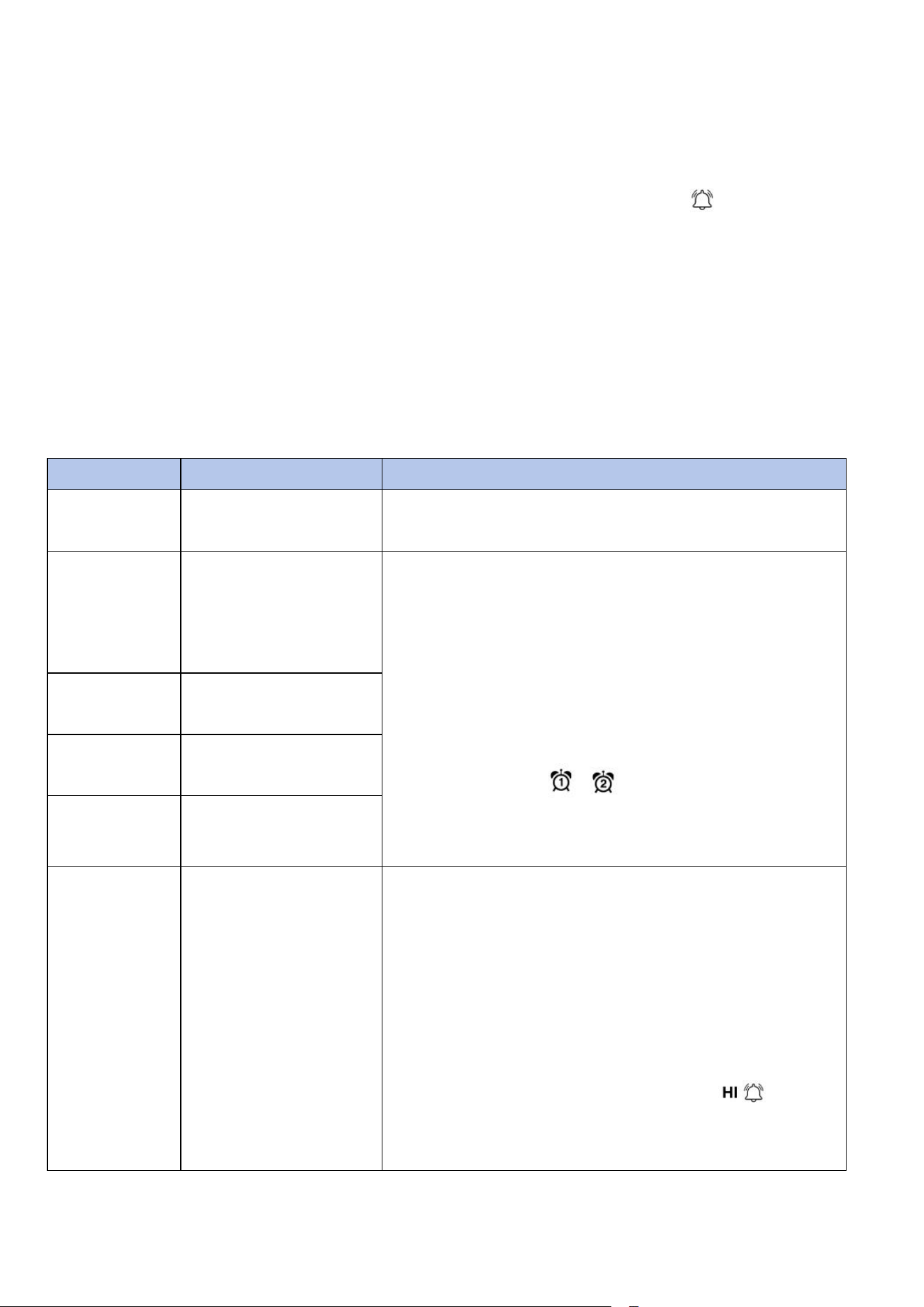
Command
Mode
Settings
[ALARM]
Enter alarm
viewing mode
[SET]+3 sec
Enter alarm
setting mode;
Hour setting
(alarm 1)
·Press the CHANNEL/+ button or the
MAX/MIN/- button to increase or decrease
the value. Long press to increase or
decrease quickly.
·Press the ALARM button to turn the time
alarm on or off. When the alarm is on, the
alarm time icon will be displayed;
when the alarm is off, the alarm time icon
will disappear.
[SET]
Minute setting
(alarm 1)
[SET]
Hour setting
(alarm 2)
[SET]
Minute setting
(alarm 2)
[SET]
Outdoor
temperature high
alarm
·Press the CHANNEL/+ key or the
MAX/MIN/- key to increase or decrease the
value. Long press to increase or decrease
quickly.
·Press the ALARM key to turn the alarm on
or off. The time area will display HI ON/OFF.
If the alarm is turned on, an icon will
be displayed next to the parameter. If the
alarm is turned off, the icon will disappear.
12
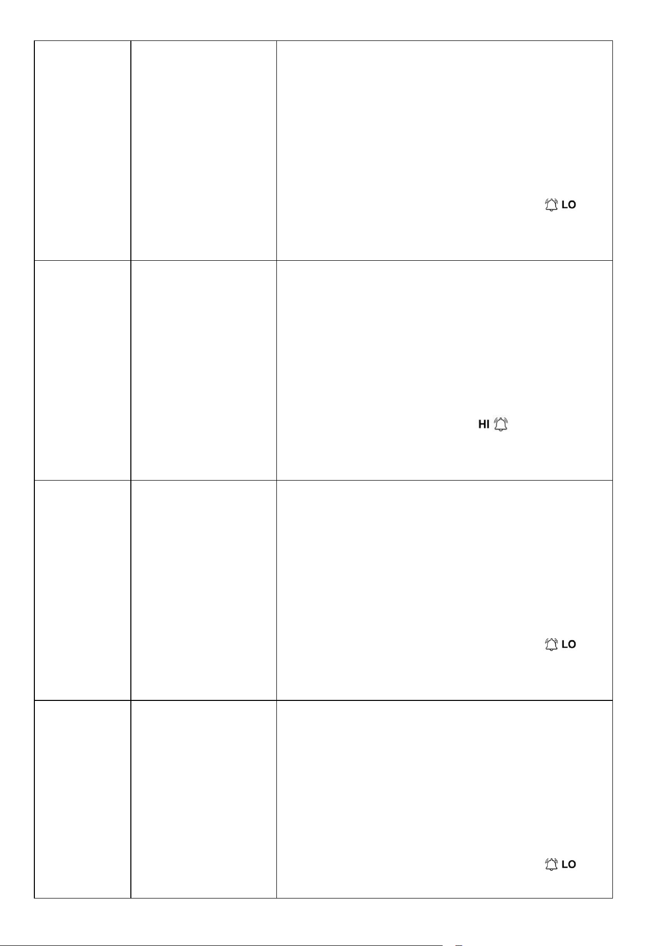
[SET]
Outdoor
temperature low
alarm
· Press the CHANNEL/+ key or the
MAX/MIN/- key to increase or decrease the
value. Long press to increase or decrease
quickly.
· Press the ALARM key to turn the alarm on
or off. The time area will display LOW
ON/OFF. If the alarm is on, an icon
will be displayed next to the parameter. If
the alarm is off, the icon will disappear.
[SET]
Outdoor humidity
high alarm
· Press the CHANNEL/+ key or the
MAX/MIN/- key to increase or decrease the
value. Long press to increase or decrease
quickly.
· Press the ALARM key to turn the alarm on
or off. The time area will display HI ON/OFF.
If the alarm is on, an icon will be
displayed next to the parameter. If the
alarm is off, the icon will disappear.
[SET]
Outdoor humidity
low alarm
· Press the CHANNEL/+ key or the
MAX/MIN/- key to increase or decrease the
value. Long press to increase or decrease
quickly.
· Press the ALARM key to turn the alarm on
or off. The time area will display LOW
ON/OFF. If the alarm is on, an icon
will be displayed next to the parameter. If
the alarm is off, the icon will disappear.
[SET]
Outdoor humidity
low alarm
· Press the CHANNEL/+ key or the
MAX/MIN/- key to increase or decrease the
value. Long press to increase or decrease
quickly.
· Press the ALARM key to turn the alarm on
or off. The time area will display LOW
ON/OFF. If the alarm is on, an icon
will be displayed next to the parameter. If
13
the alarm is off, the icon will disappear.
[SET]
Outdoor dew
point high alarm
· Press the CHANNEL/+ key or the
MAX/MIN/- key to increase or decrease the
value. Long press to increase or decrease
quickly.
· Press the ALARM key to turn the alarm on
or off. The time area will display LOW
ON/OFF. If the alarm is on, an icon
will be displayed next to the parameter. If
the alarm is off, the icon will disappear.
[SET]
Outdoor dew
point low alarm
· Press the CHANNEL/+ key or the
MAX/MIN/- key to increase or decrease the
value. Long press to increase or decrease
quickly.
· Press the ALARM key to turn the alarm on
or off. The time area will display LOW
ON/OFF. If the alarm is on, an icon
will be displayed next to the parameter. If
the alarm is off, the icon will disappear.
[SET]
Outdoor feels like
high alarm
· Press the CHANNEL/+ key or the
MAX/MIN/- key to increase or decrease the
value. Long press to increase or decrease
quickly.
· Press the ALARM key to turn the alarm on
or off. The time area will display HI ON/OFF.
If the alarm is on, an icon will be
displayed next to the parameter. If the
alarm is off, the icon will disappear.
[SET]
Outdoor feels like
low alarm
· Press the CHANNEL/+ key or the
MAX/MIN/- key to increase or decrease the
value. Long press to increase or decrease
quickly.
· Press the ALARM key to turn the alarm on
14
or off. The time area will display LOW
ON/OFF. If the alarm is on, an icon
will be displayed next to the parameter. If
the alarm is off, the icon will disappear.
[SET]
Indoor
temperature high
alarm
· Press the CHANNEL/+ key or the
MAX/MIN/- key to increase or decrease the
value. Long press to increase or decrease
quickly.
· Press the ALARM key to turn the alarm on
or off. The time area will display HI ON/OFF.
If the alarm is on, an icon will be
displayed next to the parameter. If the
alarm is off, the icon will disappear.
[SET]
Indoor
temperature low
alarm
· Press the CHANNEL/+ key or the
MAX/MIN/- key to increase or decrease the
value. Long press to increase or decrease
quickly.
· Press the ALARM key to turn the alarm on
or off. The time area will display LOW
ON/OFF. If the alarm is on, an icon
will be displayed next to the parameter. If
the alarm is off, the icon will disappear.
[SET]
Indoor humidity
high alarm
· Press the CHANNEL/+ key or the
MAX/MIN/- key to increase or decrease the
value. Long press to increase or decrease
quickly.
· Press the ALARM key to turn the alarm on
or off. The time area will display HI ON/OFF.
If the alarm is on, an icon will be
displayed next to the parameter. If the
alarm is off, the icon will disappear.
15
[SET]
Indoor humidity
low alarm
· Press the CHANNEL/+ key or the
MAX/MIN/- key to increase or decrease the
value. Long press to increase or decrease
quickly.
· Press the ALARM key to turn the alarm on
or off. The time area will display LOW
ON/OFF. If the alarm is on, an icon
will be displayed next to the parameter. If
the alarm is off, the icon will disappear.
[SET]
Absolute pressure
high alarm
· Press the CHANNEL/+ key or the
MAX/MIN/- key to increase or decrease the
value. Long press to increase or decrease
quickly.
· Press the ALARM key to turn the alarm on
or off. The time area will display HI ON/OFF.
If the alarm is on, an icon will be
displayed next to the parameter. If the
alarm is off, the icon will disappear.
[SET]
Absolute pressure
low alarm
· Press the CHANNEL/+ key or the
MAX/MIN/- key to increase or decrease the
value. Long press to increase or decrease
quickly.
· Press the ALARM key to turn the alarm on
or off. The time area will display LOW
ON/OFF. If the alarm is on, an icon
will be displayed next to the parameter. If
the alarm is off, the icon will disappear.
[SET]
Relative
pressure high
alarm
· Press the CHANNEL/+ key or the
MAX/MIN/- key to increase or decrease the
value. Long press to increase or decrease
quickly.
· Press the ALARM key to turn the alarm on
or off. The time area will display HI ON/OFF.
If the alarm is on, an icon will be
displayed next to the parameter. If the
16
*[ALARM] means press the ALARM button.
*[SET] means press the SET button.
*[SET]+3 sec means press and hold the SET key for three seconds;
3.4.3. Alarm Triggered
When an alarm condition is exceeded, the alarm icon will flash (visual) and
the alarm beeper will sound (audible). To silence the beeper, press any key.
3.4.4. Button Beeper ON/OFF
In normal mode, press and hold the ALARM key for three seconds to toggle
the BZ ON(beeper on) or BZ OFF(beeper off) depending on the current setting.
Display console return to normal mode without any operation in three
seconds.
3.5. Snooze Mode
If the time alarm sounds and you wish to silence the alarm, press the SNOOZE
key. The alarm icon will continue to flash and the alarm will silence for five
minute.
Press any other key to permanently exit the SNOOZE mode.
alarm is off, the icon will disappear.
[SET]
Relative
pressure low
alarm
· Press the CHANNEL/+ key or the
MAX/MIN/- key to increase or decrease the
value. Long press to increase or decrease
quickly.
· Press the ALARM key to turn the alarm on
or off. The time area will display LOW
ON/OFF. If the alarm is on, an icon
will be displayed next to the parameter. If
the alarm is off, the icon will disappear.
17
3.6. Backlight Mode
In normal mode, there are 3 levels of brightness of display backlight.
When the backlight is ON with adapter power, press SNOOZE key to switch
between the 3 levels.
In the brightest level, press the SNOOZE key to turn off the backlight. Press the
SNOOZE key again and the backlight will light for 3 levels adjustable backlight.
Note: If the display console plugged into adapter power, the time area will
display BL ON and the backlight will remain on. You can press and hold
the SNOOZE button to turn ON/OFF backlight permanently.
Note: It is not recommended leaving the display backlight on for a long
period of time when operating on batteries only, or the batteries will run
out quickly.
4. Display connected to WiFi
4.1. Real-time Network Monitoring
The weather station can upload data to the following two platforms:
*Weather station use the WiFi connection to send data to the Internet.
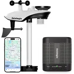
4.2. APP Download
Please search "Weatherseed" APP in Google Play or IOS App Store. After
downloading, you can follow the steps of WiFi connection to connect the
weather station to WiFi and then view the data on the APP!
Application Services
Description
Weatherseed APP
Our weather stations feature the most
user-friendly design to monitor data
across different platforms. Use our
animated expandable modules to quickly
view the details you want.
18
4.3. APP Account Register and Login
After successfully downloading “Weatherseed” APP, please open the APP, the
first time you open the APP, the login or registration screen will appear. If you
don't have an account for the first time, you need to register your own account
to log in later; if you have already registered a Weatherseed account, you can
log in directly without registering again.
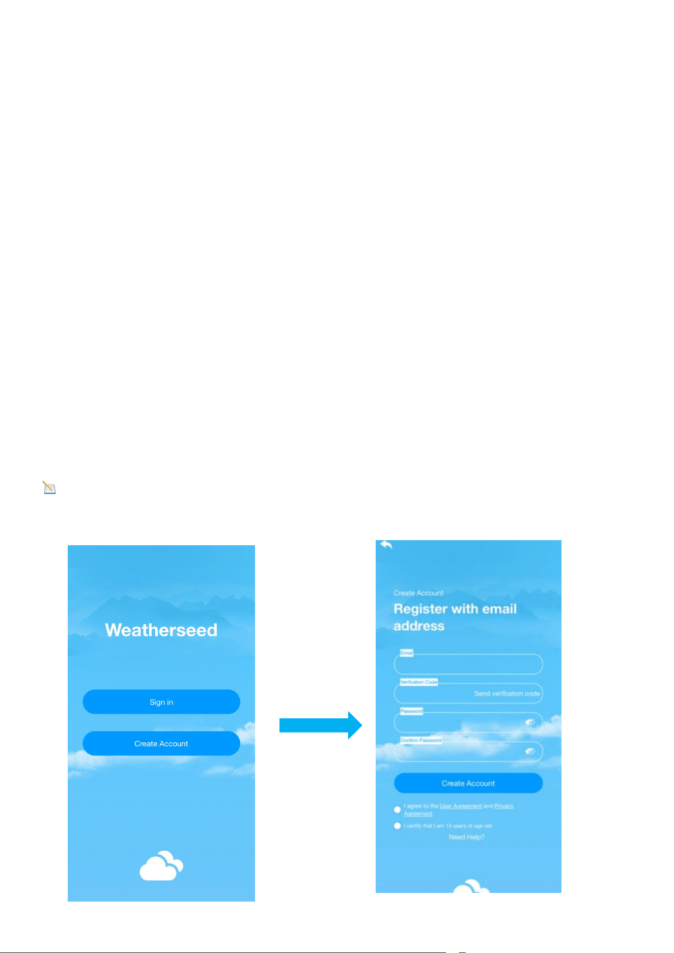
4.3.1. Registering Process
You can follow the steps and pictures below to register your Weatherseed
account:
(1) Fill in your e-mail address;
(2) Send the verification code to the e-mail address;
(3) Go to the e-mail address to check the verification code and enter it;
(4) Set a password;
(5) Confirm the password (must be consistent with the set password);
(6) Check the user agreement and proof of age;
(7) Register an account.
Note: Your account will be automatically logged in the APP directly after the
registration is completed.
19
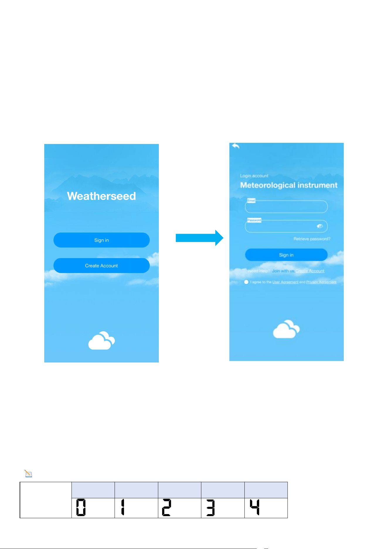
4.3.2. Login Process
You can follow the steps and picture instructions below to log in to your
Weatherseed account:
(1) Enter your registered Weatherseed account (Email address);
(2) Enter the password you have set;
(3) Check the User Privacy Agreement;
(4) Log in to your account.
4.4. MAC Address
In normal mode, double-click the CHANNEL/+ key on the display, the MAC icon
will be shown in the date area , the MAC address will flash one by one in
sequence, and it will automatically return to the normal mode when all the
addresses are displayed.
Note: Comparison table of numbers and letters
Numbers
0
1
2
3
4

20
5
6
7
8
9
Letters
A
b
C
d
E
F
4.5. IP Address
In normal mode, double-click the MAX/MIN/- key on the display, the IP icon will
be shown in the date area, the IP address will flash in sequence one by one, and
it will automatically return to normal mode when all the addresses are
displayed.
5.Connecting Steps
Note: The display console only supports 2.4 GHz signals. If you have a
dual-band router (2.4 GHz and 5.0 GHz), please make sure that the router's 2.4
GHz band is turned on and can be distinguished from the 5.0 GHz channel's SSID
for accurate connection to the 2.4 GHz channel.
Note : The power adapter needs to be plugged into connect to WiFi.
Battery power cannot connect to WiFi.
Note
:
Please don't choose the wrong type and model , if you choose the
wrong one, you can't match the network successfully.
Note
:
If the device is frequently offline, it must be reset. The router should
always be on, it will show offline after no WiFi.
21
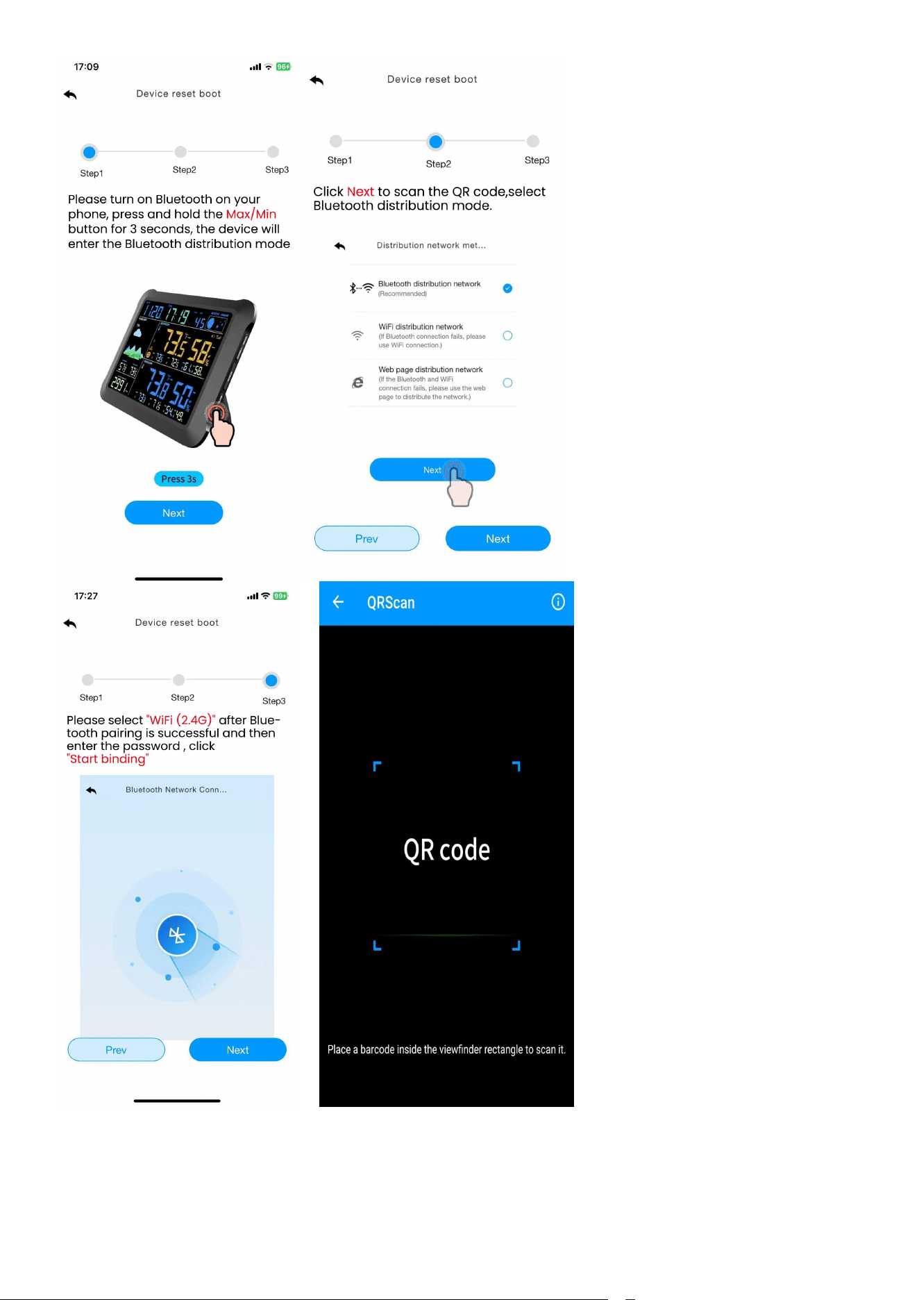
5.1. Bluetooth Distribution Network Mode
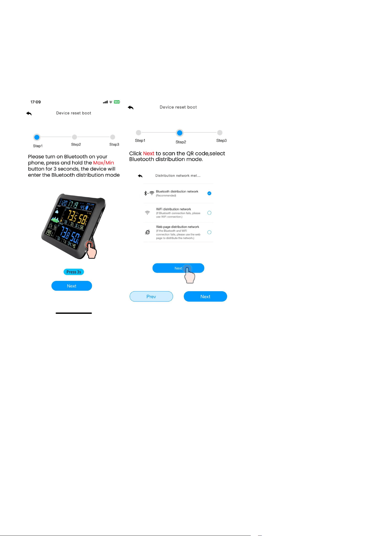
The display enters the distribution mode by pressing and holding the
MAX/MIN/- key, the WiFi icon will flash and the BI icon will be shown in the
date area, which indicates that the display has entered the ”Bluetooth
distribution network” mode.
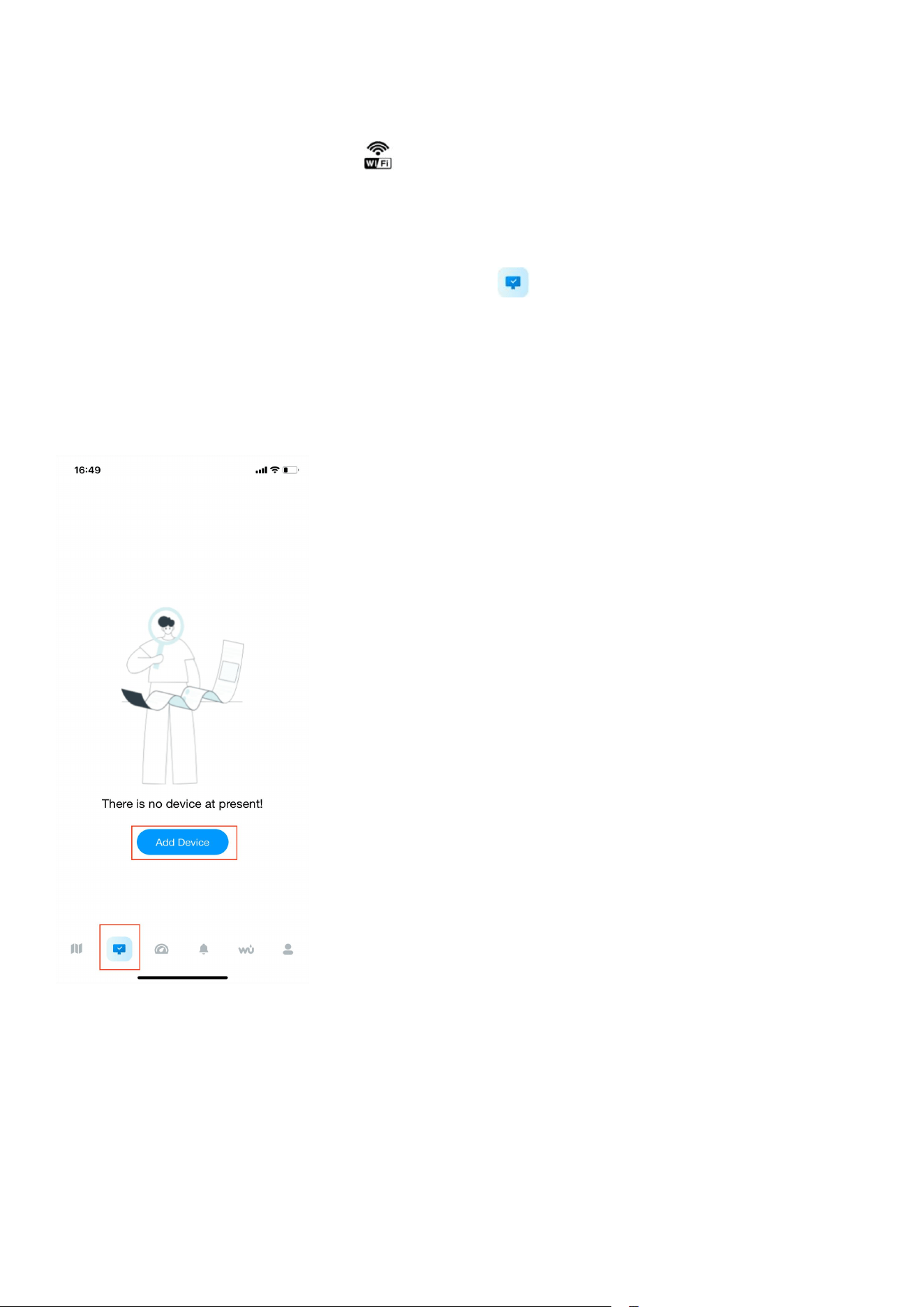
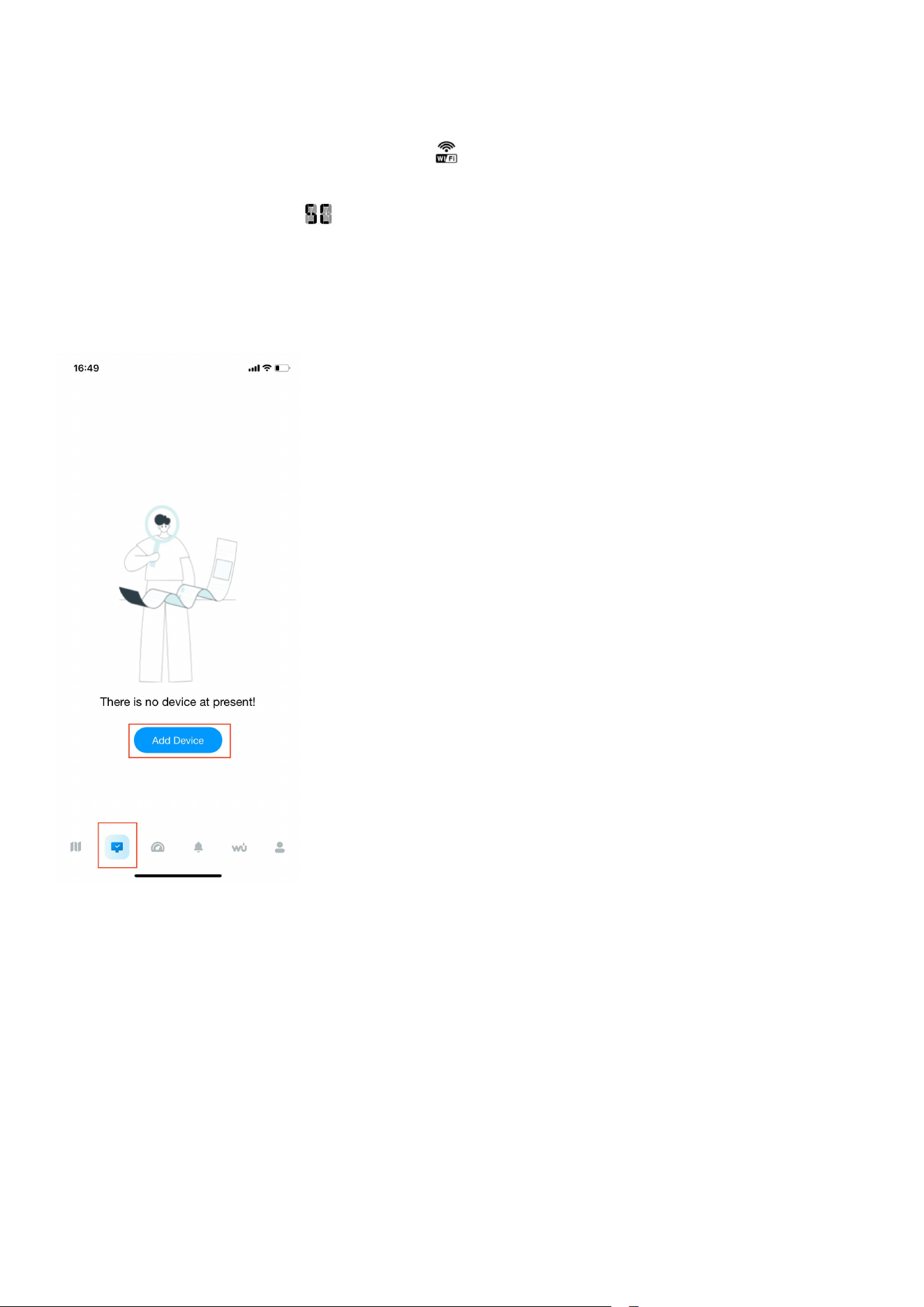
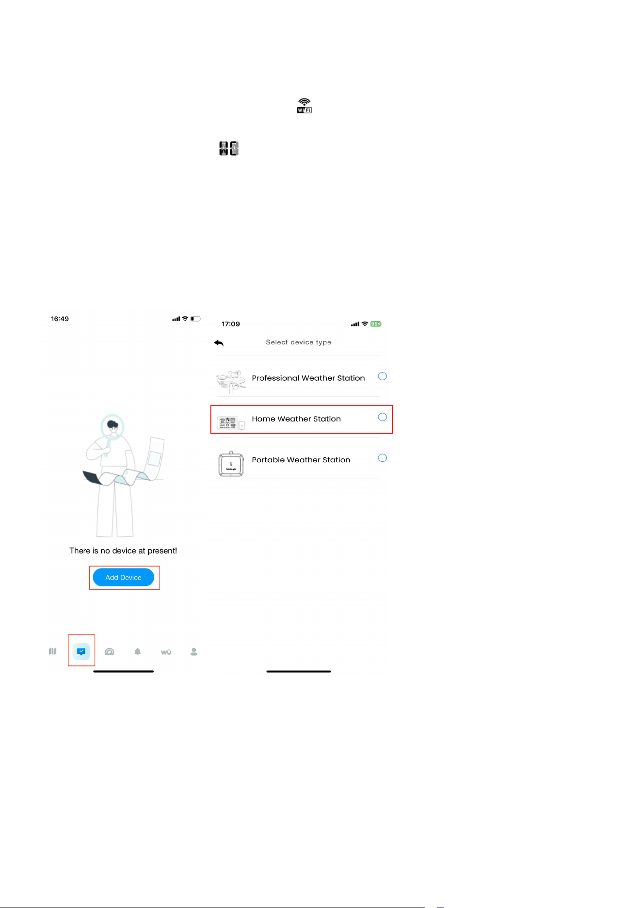
After the display has entered the ”Bluetooth distribution network” mode,
please open the APP, select the second icon on the lower left to enter the
networking interface to start networking, the specific steps and picture
instructions are as follows:
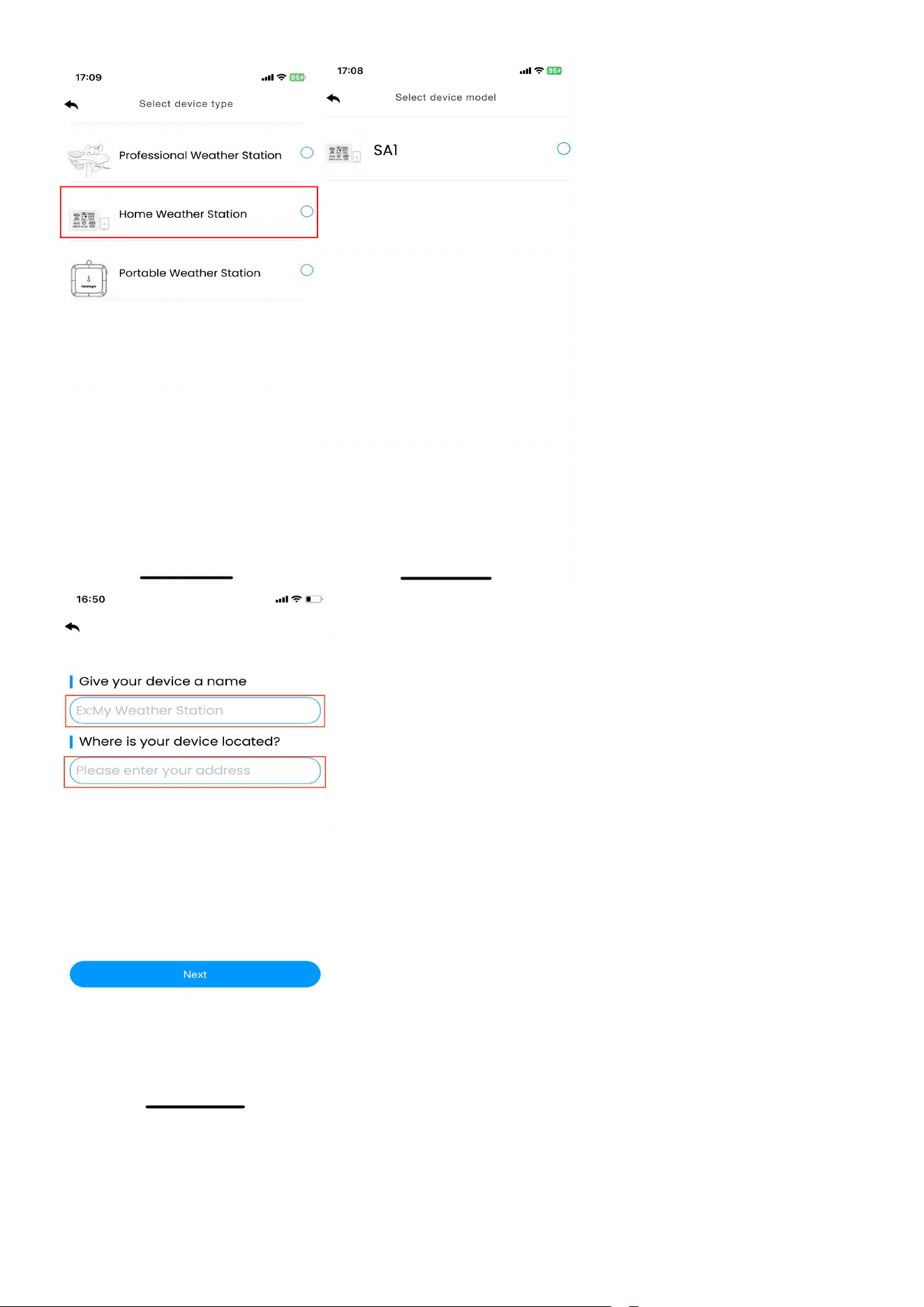
(1)Enter the networking interface, click "Add Device" to start connecting the
Wifi ;
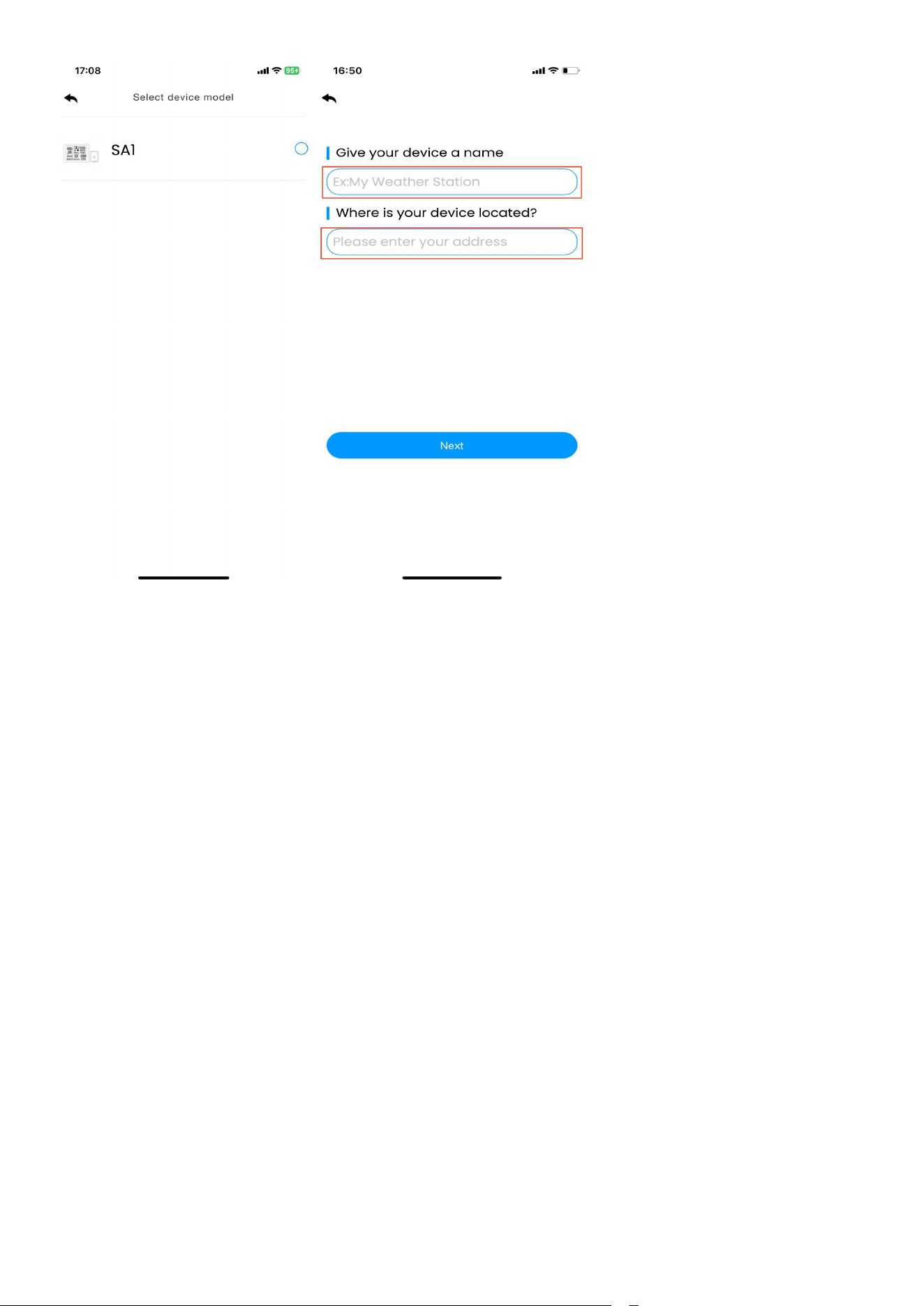
(2) Add the device in the app, select the device type and model, and set a
weather station name, enter your location.
22

23
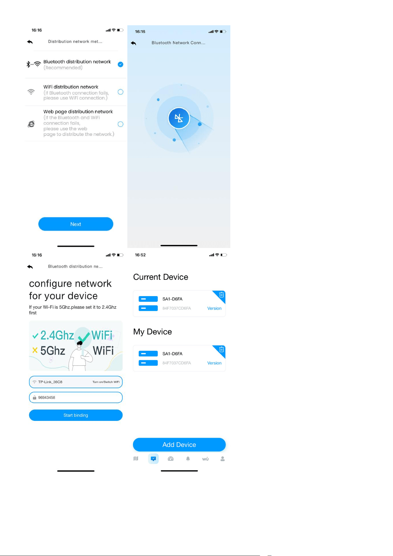
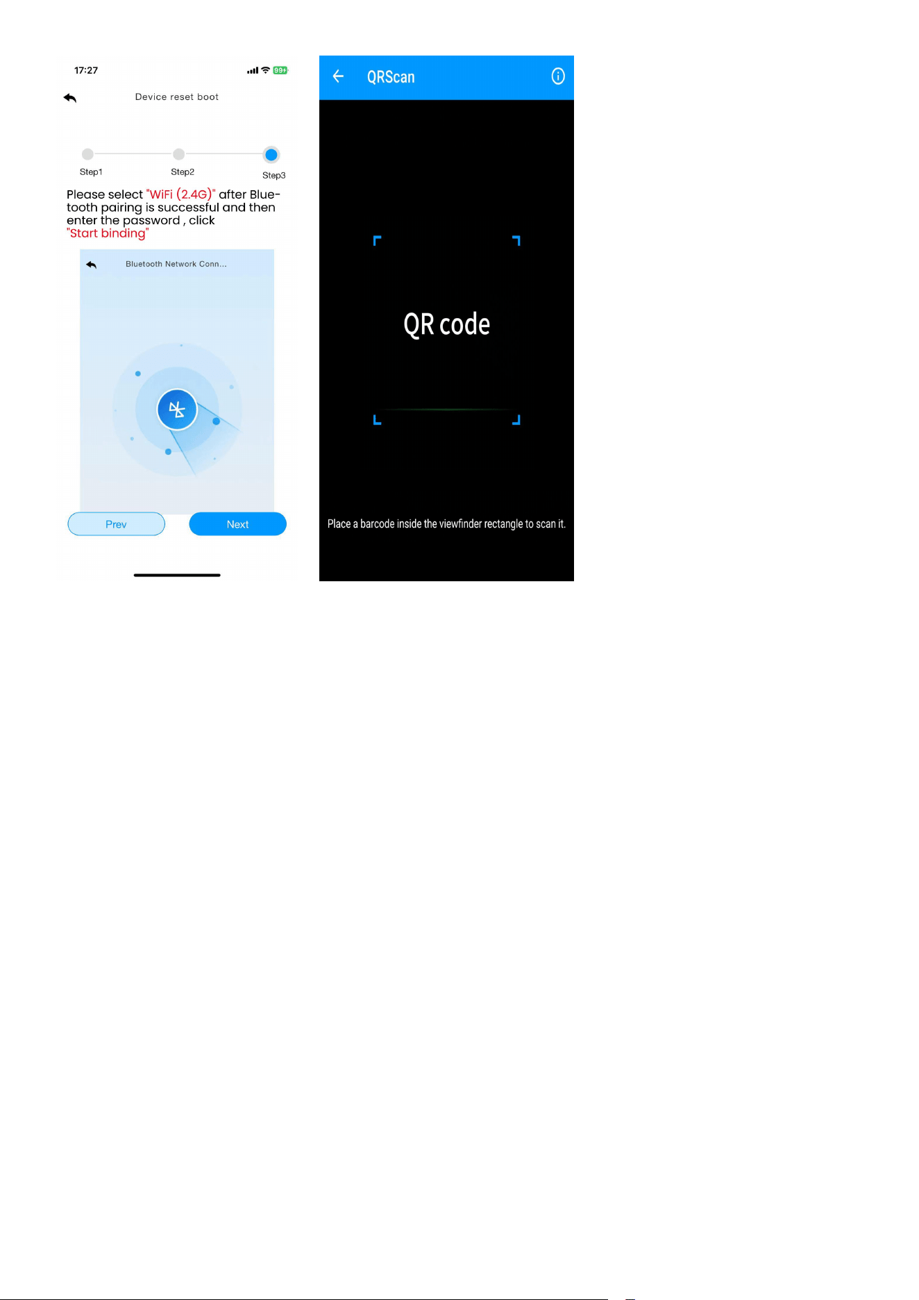
(3)Enter the network configuration interface and click “Next” to complete the
three steps of network configuration. Then need to scan the QR code (Mac
address) of the device.

24
(4)Select the”Bluetooth distribution network” mode to automatically search for
Bluetooth signals and pairing.
After successful pairing, jump to WiFi interface. Please select 2.4ghz wifi and
enter the password.
25
26
5.2. WiFi Distribution Network Mode
In normal mode, press and hold MAX/MIN/- key for at least 5 seconds to enter
WiFi distribution mode, the WiFi icon will be flashing and the BI icon will be
displayed in the date area, then short press the SET key once, the BI icon will be
converted to the SC icon , which indicates that the display has entered the
“WiFi distribution network” mode.
(1)Enter the networking interface, click "Add Device" to start connecting the
Wifi ;
(2)Add the device in the app, select the device type and model, and set a
weather station name, enter your location.

27
28
(3)Enter the network configuration interface and click “Next” to complete the
three steps of network configuration. Then need to scan the QR code (Mac
address) of the device.
29
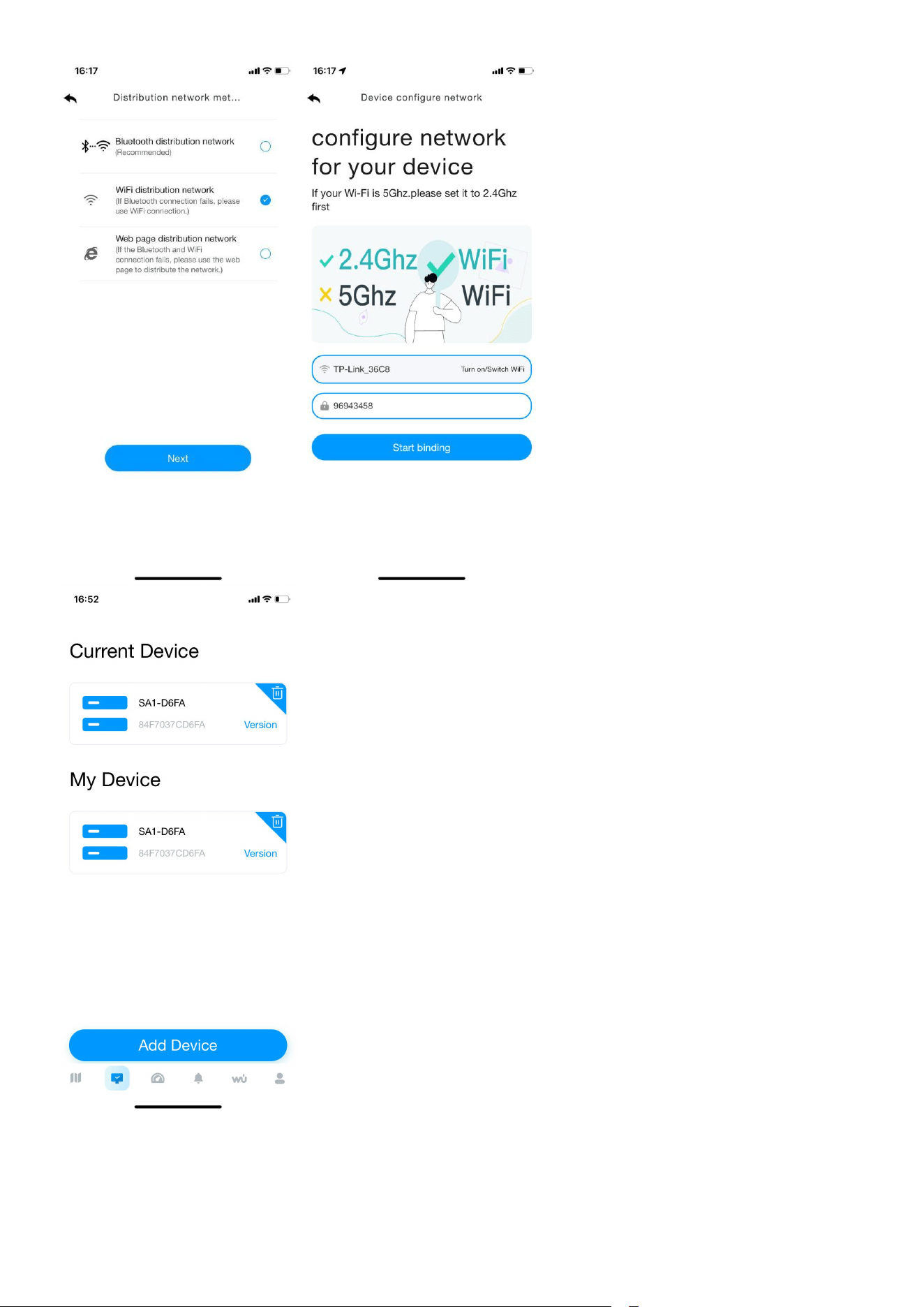
(4) Select the distribution network mode: “Wifi distribution network”.
Select your own WiFi (2.4g), enter the correct password and connect the device.
After the connection is successful, you will go back to Device page.
30
31
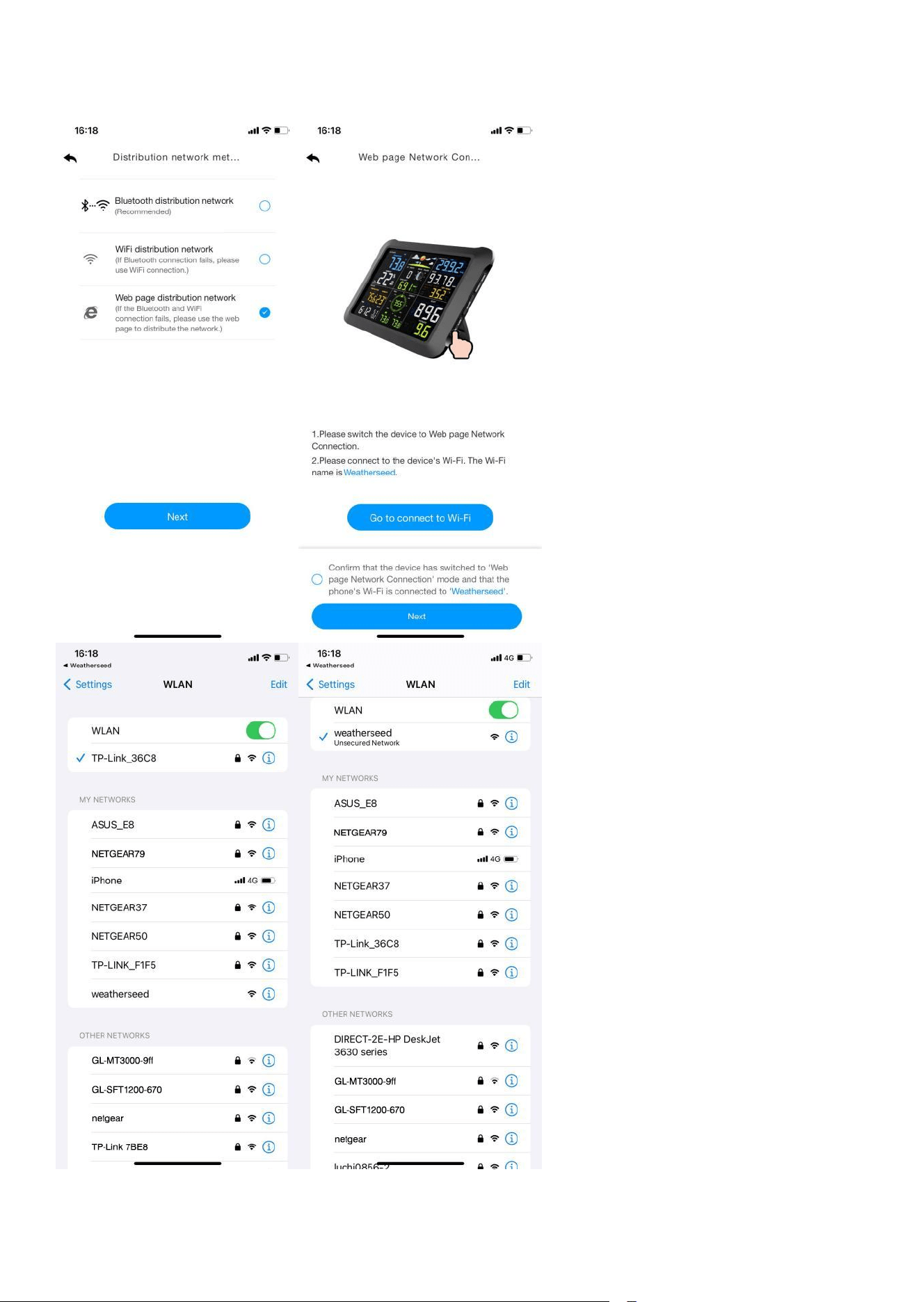
5.3. Web page distribution network mode
In normal mode, press and hold MAX/MIN/- key for at least 5 seconds to enter
wifi distribution mode, the WiFi icon will be flashing and the BI icon will be
displayed in the date area, then short press the SET key twice, the icon will be
converted to the WC icon , which indicates that the display has entered the
“Web page distribution network” mode.
After the display has entered the “Web page distribution network” mode,
please follow the steps below and the picture instructions to connect:
(1) Add device in the dashboard interface. Select device type and model, and
set a weather station name, enter your location.
32
(2)Enter the network configuration interface and click “Next” to complete the
three steps of network configuration. Scan the QR code.
33
(3)Select “Web page distribution network” mode , Click Go to connect WiFi.
34
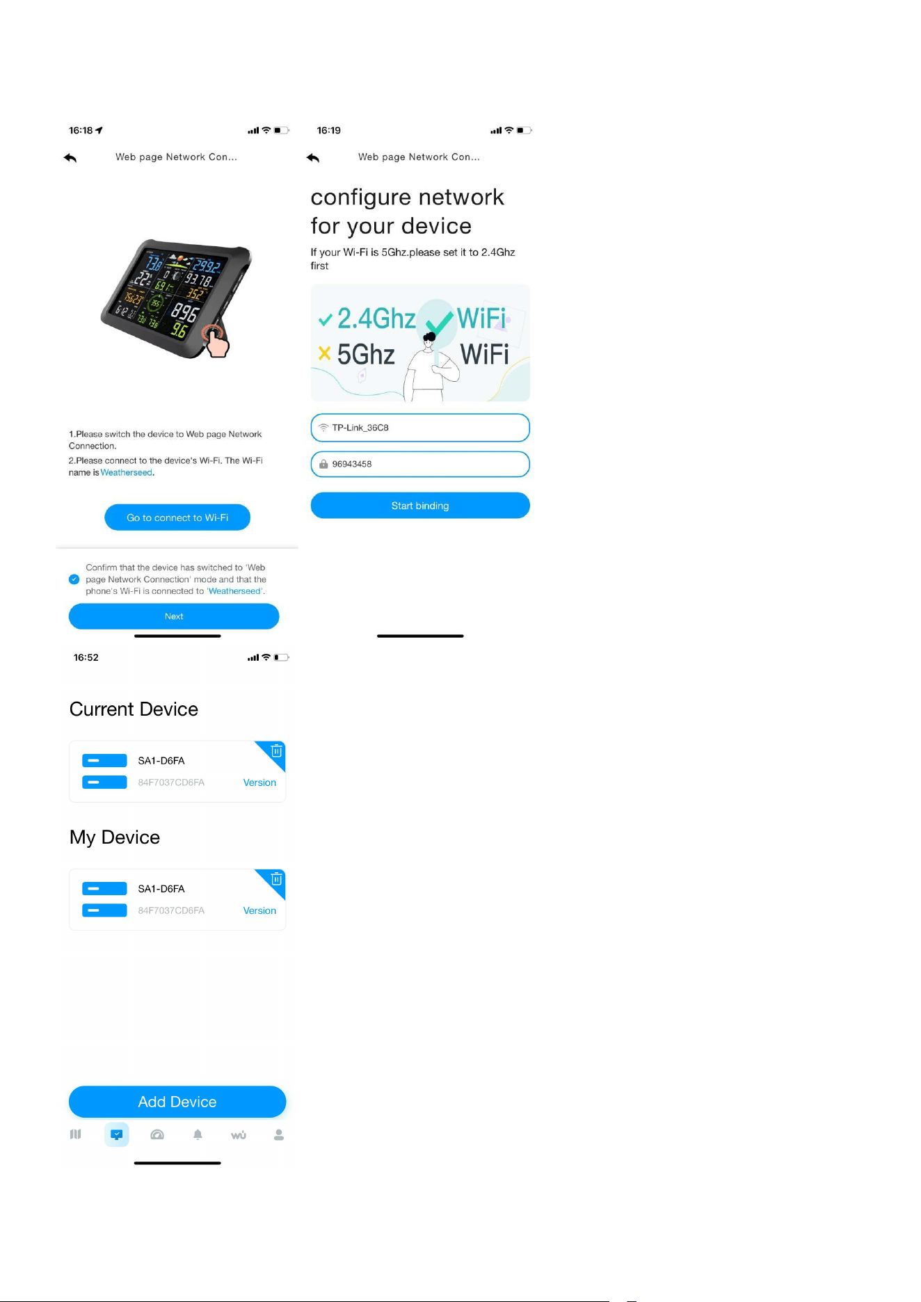
Then will automatically jump to the WiFi list screen, click Connect “weatherseed”
WiFi.
35
Return to the app, click the confirmation dot and click “Next”. Please select
2.4ghz WiFi, enter the password and click Connect.
36
Note: Android system can select WiFi. IOS system needs to manually enter the
WiFi name.
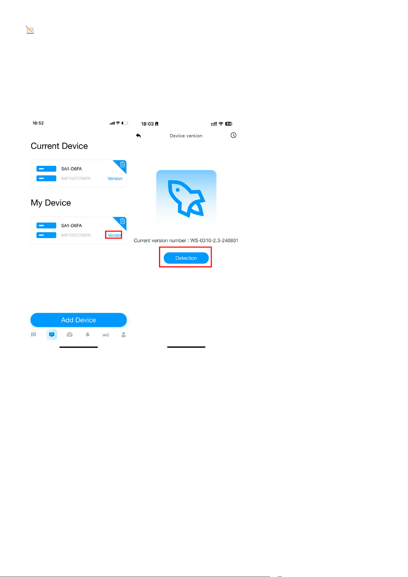
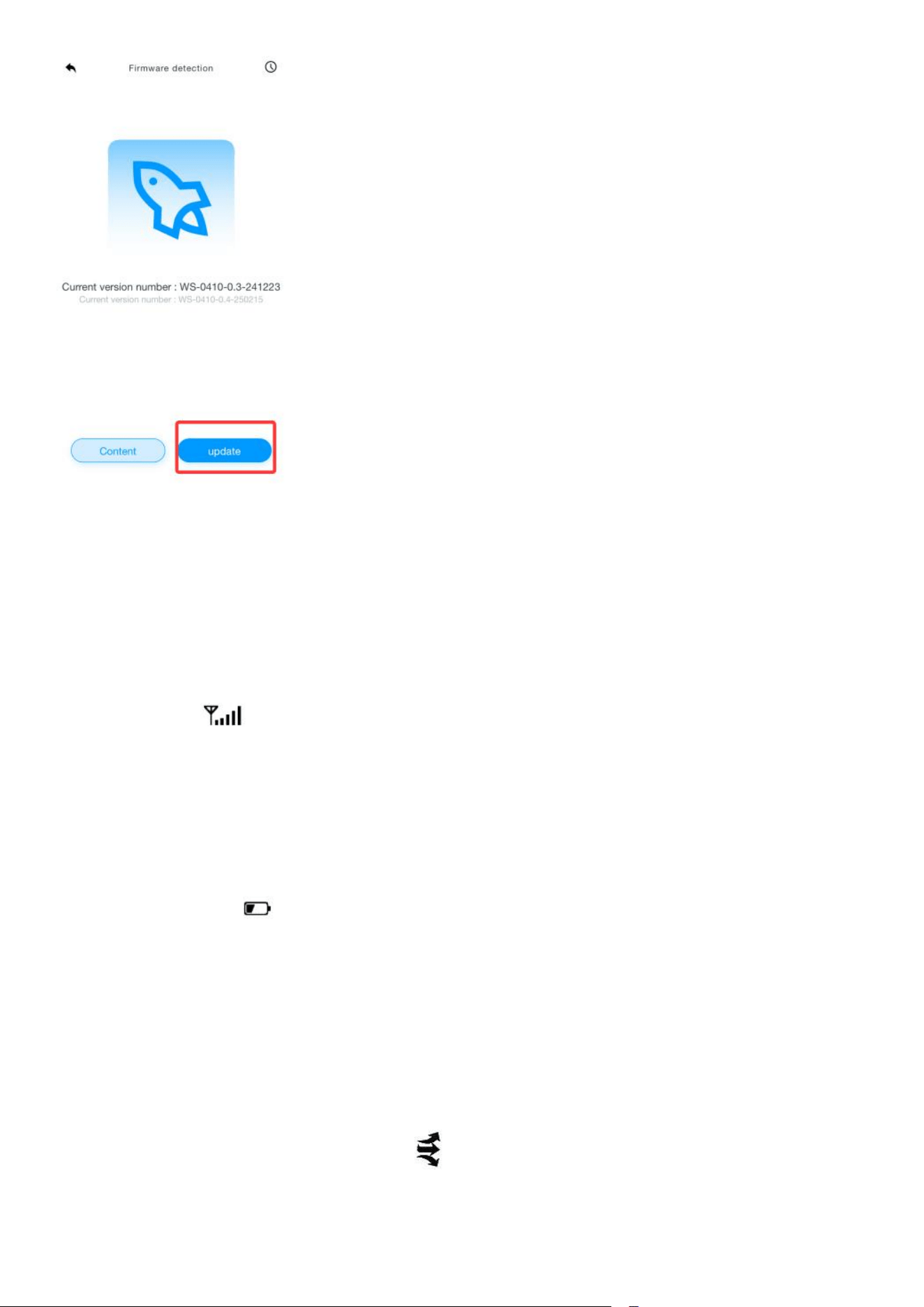
6.Firmware Upgrade
When your app receives a firmware upgrade notification, follow the steps below
to remotely upgrade the firmware.
37
7. Sensor Search Mode
If the sensor communication is lost, dashes (--.-) will be
displayed on the screen.
Press and hold the CH/+ button for 3 seconds to enter sensor search mode. The
search icon will be displayed constantly for 3 minutes.
If all the time the data keeps showing a dotted line, press the button on the right
side of the temperature and humidity sensor. The temperature and humidity
sensor will flash red and wait a moment for the display to search for the signal.
8. Battery Icon
The battery icon indicates that the display has power and is powered by the
power adapter or batteries.
9. Rate of Change Icon
The rate of change icon detects rapid changes in
temperature and humidity.

38
If the arrow points upward, the temperature is increasing at a rate of +2°F per
30 minutes (or greater). If the arrow points downward, the temperature is
decreasing at a rate of -2°F per 30 minutes (or less).
If the arrow points upward, the humidity is increasing at a rate of +5% per
30 minutes (or greater). If the arrow points downward, the
humidity is decreasing at a rate of -5% per 30 minutes (or less).
10. Calibration Mode
Note: The calibrated value can only be adjusted on the console. The
remote sensor always displays the un-calibrated or measured value.
Note: The measured humidity range is between 10 and 99%.
Humidity cannot be accurately measured outside of this range. Thus, the
humidity cannot be calibrated below 10% or above 99%.
The purpose of calibration is to fine tune or correct for any sensor error
associated with the devices margin of error. The measurement can be
adjusted from the console to calibrate to a known source.
Calibration is only useful if you have a known calibrated source you can
compare it against, and is optional. This section discusses
practices, procedures and sources for sensor calibration to
reduce manufacturing and degradation errors. Do not compare your
readings obtained from sources such as the internet, radio, television or
newspapers. They are in a different location and typically update once
per hour.
The purpose of the weather station is to measure conditions of your
surroundings, which vary significantly from location to location.

39
10.1. Temperature Calibration
In normal mode, press and hold the SET and CHANNEL/+ keys at the
same time for five seconds to enter the temperature
calibration mode. The indoor temperature will begin flashing.
Press the [+] or [-] key to increase or decrease
the temperature reading (in increments of 0.1). Press and hold the [+] or [-] key
for three seconds to increase or decrease rapidly.
Press the ALARM key and reset to current value.
Press the SET key switch to sensor temp calibration mode.
Press the SET key to exit calibrated mode, or press the
SNOOZE button at any time.
The following chart summarizes the temperature calibration mode sequence
and commands.
Command
Mode
Settings
[SET]and[C
HANNEL/+]
+5 sec
Enter the
temperature
calibration mode;
Indoor temperature
calibration
- Press the CHANNEL/+ key or
MAX/MIN/- key to increase or
decrease the temperature reading (in
0.1 increments).
- Press and hold the CHANNEL/+ key
or MAX/MIN/- key for three seconds
to quickly increase or decrease the
temperature reading.
- Press the ALARM key to reset the
current value.

40
*[SET] and [CHANNEL/+]+5 sec means press and hold SET and CHANNEL/+ key
for at least 5 seconds;
*[SET] means press the SET button.
10.2. Humidity Calibration
In normal mode, press and hold the SET and MAX/MIN/- keys at the same
time for five seconds to enter the humidity calibration mode.
The indoor humidity will begin flashing.
Press the [+] or [-] key to increase or decrease the humidity reading (in
increments of 1%). Press and hold the [+] or [-] key for three seconds to increase
or decrease rapidly.
Press the ALARM key and reset to current value.
Press the SET key switch to sensor humidity calibration mode.
Press the SET key to exit calibrated mode, or press the
SNOOZE button at any time.
The following chart summarizes the sequence and commands for the humidity
calibration mode.
[SET]
Outdoor
temperature
calibration
- Press the CHANNEL/+ key or
MAX/MIN/- key to increase or
decrease the temperature reading (in
0.1 increments).
- Press and hold the CHANNEL/+ key
or MAX/MIN/- key for three seconds
to quickly increase or decrease the
temperature reading.
- Press the ALARM key to reset the
current value.
[SNOOZE]
Exit temperature
calibration mode
If no operation is performed, the
calibration mode will time out and exit
after 30 seconds.
Command
Mode
Settings

41
*[SET] and [MAX/MIN/-] +5 sec means press and hold SET and CHANNEL/+ key
for at least 5 seconds;
*[SET] means press the SET button.
Note: Humidity is a difficult parameter to measure
accurately and drifts over time. The calibration feature allows you to zero out
this error. To calibrate humidity, you will need an accurate source, such as a
sling psychrometer or
Humidipaks One Step Calibration kit.
[SET]and[M
AX/MIN/-]+
5 sec
Enter the
Humidity
Calibration
Mode;
Indoor humidity
calibration
- Press the CHANNEL/+ key or MAX/MIN/-
key to increase or decrease the humidity
reading (in 1% increments).
- Press and hold the CHANNEL/+ key or
MAX/MIN/- key for three seconds to
quickly increase or decrease the humidity
reading.
- Press the ALARM key to reset the
current value.
[SET]
Outdoor humidity
calibration
- Press the CHANNEL/+ key or MAX/MIN/-
key to increase or decrease the humidity
reading (in 1% increments).
- Press and hold the CHANNEL/+ key or
MAX/MIN/- key for three seconds to
quickly increase or decrease the humidity
reading.
- Press the ALARM key to reset the
current value.
[SNOOZE]
Exiting Humidity
Calibration Mode
If no operation is performed, the
calibration mode will time out and exit
after 30 seconds.

42
10.3. Pressure Calibration
In normal mode, press and hold the SET and ALARM keys at the same time for
five seconds to enter the pressure calibration mode.
Absolute Pressure Calibration.
Press the [+] or [-] key to increase or decrease the pressure reading (in
increments of 0.00 inHg) Press and hold the [+] or [-] key for three seconds to
increase or decrease rapidly.
Press the ALARM key and reset to current value.
Relative Pressure Calibration
press the SET button again, the “ REL” symbol will display at the pressure
section, the relative pressure value will flash. (The default value is
0.00 inHg)
Press the the [+] or [-] key to increase or decrease the relative pressure value
(in increments of 0.01 inHg). Press and hold the [+] or [-] key for three seconds
to increase or decrease rapidly.
Press the ALARM key and reset to current value.
Press the SET key to exit calibrated mode, or press the
SNOOZE button at any time.
Example: The calibrated pressure sources measure 25.00 inHg.
The display console pressure reads 24.85 inHg. Offset = 25.00 - 24.85 = 0.15
inHg
Note: The display console displays two different pressures: absolute
(measured) and relative (corrected to sea-level).
To compare pressure conditions from one location to another, meteorologists
correct pressure to sea-level conditions. Because the air pressure

43
decreases as you rise in altitude, the sea-level corrected pressure (the pressure
your location would be at if located at sea-level) is generally
higher than your measured pressure.
Thus, your absolute pressure may read 28.62 inHg (969 mb) at an altitude of
1000 feet (305 m), but the relative pressure is 30.00 inHg (1016 mb).
The standard sea-level pressure is 29.92 in Hg (1013.2hpa). This is the
average sea-level pressure around the world. Relative pressure
measurements greater than 29.92 inHg (1013.2hpa) are
considered high pressure and relative pressure measurements
less than 29.92 inHg are considered low pressure.
To determine the relative pressure for your location, locate an official reporting
station near from you (the internet is the best source for real-time barometer
conditions, such as the website of Weather.com or Wunderground.com), and
set your weather station to match the official reporting station.
11. Factory Default Reset
To reset the console to factory default, press the MAX/MIN/- key while
plugging in power adapter simultaneously ( Take out batteries before starting
the reset operation ).
12. Other Console Features
The following section describes additional features and display icons.
12.1. Weather Forecasting
The weather forecast is an estimation or generalization of weather changes in
the next 24 to 48 hours, and varies from location to location. The tendency is
simply a tool for projecting weather conditions and is never to be relied upon
as an accurate method to predict the weather.
The reason the current conditions don't match the forecast icon is that the
forecast is an estimate or summary of how the weather will change over the
44
next 24-48 hours, which varies from place to place. Weather trends are only a
tool to predict how the weather will change, and should never be relied upon as
an accurate method of predicting the weather. In most areas, these predictions
are only 70% accurate, so it's best to consult the National Weather Service for a
more accurate weather forecast.
Note: The weather forecast or pressure tendency is based on the rate of
change of barometric pressure. In general, when the pressure increases, the
weather improves (partly cloudy to sunny ) and when the pressure decreases,
the weather degrades (cloudy to rain).
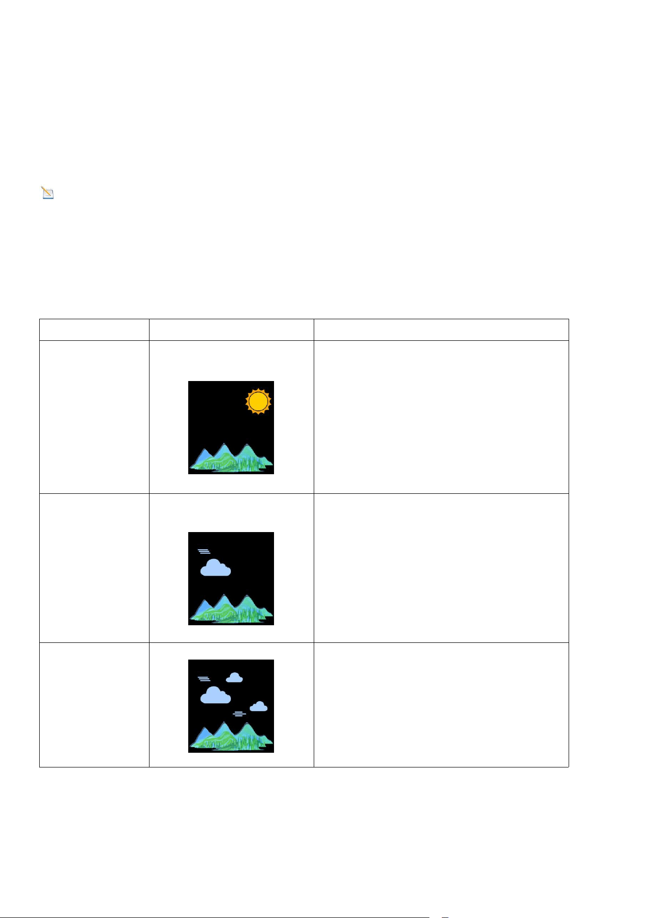
12.2. Weather Icons
Condition
Icon
Description
Sunny
Pressure is rising and the
previous condition is partly
cloudy.
Partly
Cloudy
Pressure is falling and the
previous condition is sunny or
Pressure is rising and the previous
condition is cloudy.
Cloudy
Pressure is falling and the
previous condition is partly
cloudy or Pressure is rising and
the previous condition is rainy.
45
Rainy
Pressure is falling and the
previous condition is cloudy
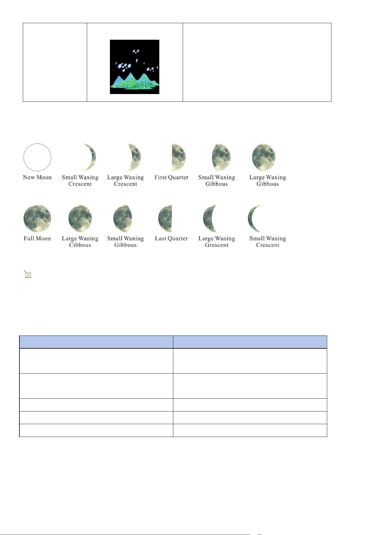
13. Moon Phase
Note: The new moon does not show the phases of the moon.
14. Specifications
14.1. Wireless Specifications
Wireless transmission
Specifications
Line of sight wireless sensor array
RF transmission (open air)
330 ft(100m), 90 ft(30m) in most
cases
Line of sight Wi-Fi RF transmission
(open air)
80 ft(24m)
Outdoor sensor update frequency
16 sec
Sensor array RF frequency
433 MHz
Wi-Fi console RF frequency
2.4 GHz
14.2. Measurement Specifications

46
Measurement
Range
Accuracy
Resolution
Indoor
Temperature
32 to 140°F (0
to 60°C)
± 2°F
(± 1°C)
0.1°F
(0.1°C)
Outdoor
Temperature
- 40 to140°F
(-40 to 60°C)
± 2°F
(± 1°C)
0.1°F
(0.1°C)
Indoor
Humidity
10 to 99 %
± 5% (only
guaranteed
between 20 to
90%)
1 %
Outdoor
Humidity
10 to 99%
± 5% (only
guaranteed
between 20 to
90%)
1 %
Barometric
Pressure:
8.85 to 32.50
inHg
(300 to 1100
hpa)
± 0.08 inHg
(±3 hpa)
0.01inHg
(0.1 hpa)
14.3. Power Consumption
Base station (display console) : 3 x AAA 1.5V Alkaline or Lithium batteries
(not included)
Adaptor: 5V ~ 1000mA (included)
Remote Sensor : 3 x AAA alkaline batteries or Lithium batteries (not
included)
Battery life: Minimum 3 months for sensor (use lithium batteries in cold
weather climates less than -20 °C)
15. Troubleshooting Guide
If your question is not answered here, you can contact us by Customer Support
Email, Customer Support Phone and Website
(1) Customer Support Email:info@sainlogic.com

47
(2) Website:https://www.sainlogic.com/
(3) Customer Support Phone:+1 (888) 513-9823 (Mon-Fri 10 a.m. - 6 p.m,
Eastern Standard Time)
Problem
Solution
Wireless remote
not
reporting in to
console. There
are dashes (--.-)
on the display
console.
If the sensor communication is lost, dashes (--.-) will be
displayed on the screen. To reacquire the signal, press
and hold the CHANNEL/+ button for 3 seconds, the
remote search icon will be constantly displayed.
After reacquiring the signal, the current value will be
displayed.
If the signal cannot be searched by pressing and
holding the CHANNEL/+ button, you need to press and
hold the button switch on the right side of the small
sensor.
After blinking the red light once and then press and
hold the CHANNEL/+ button again, the device will
automatically search for the signal.
The maximum line of sight communication range is
100 m and 30 m under most conditions. Move the
sensor assembly closer to the display console.
If the sensor assembly is too close (less than 1.5m),
move the sensor assembly away from the display
console.
Make sure the remote sensor LCD display is working
and the transmitter light is flashing once per 60
seconds.
Install a fresh set of batteries in the remote
thermo-hygrometer. For cold weather environments,
install lithium batteries.

48
Make sure the remote sensor LCD display is working
and the transmitter light is flashing once per 60
seconds.
Install a fresh set of batteries in the remote
thermo-hygrometer. For cold weather
environments, install lithium batteries.
Move the remote sensor to a higher location. Move the
remote sensor to a closer location.
Temperatur
e
sensor
reads
too high in
the day time.
Make sure the sensor is mounted in a shaded area. The
preferred location is a north facing wall because it is in the
shade most of the day.
Indoor and
Outdoor
Temperature
do not
agree
Allow up to one hour for the sensors to stabilize due to
signal filtering. The indoor and outdoor temperature
sensors should agree within 4 °F (the sensor accuracy is ±
2 °F).
Use the calibration feature to match the indoor and
outdoor temperature to a known source.
Indoor and
Outdoor
Humidity do
not agree
Allow up to one hour for the sensors to stabilize due to
signal filtering. The indoor and outdoor humidity sensors
should agree within 10 % (the sensor accuracy is ± 5 %).
Use the calibration feature to match the indoor and
outdoor humidity to a known source.
16. Disclaimer
Please protect the environment by returning used batteries to an authorized
recycling station. Electrical and electronic waste contains hazardous substances.
Disposal of e-waste in the natural environment and/or in unauthorized locations
can damage the environment.

49
Reading the user manual is strongly recommended and the manufacturer and
supplier cannot be held responsible for any incorrect readings or consequences
resulting from failure to read the manual carefully.
This product is intended for home use only and is not intended for medical
purposes or public safety information. This product is not a toy and should be
kept out of the reach of children.
We assume no liability for accidental, consequential, punitive or other similar
damages related to operation or malfunction.
17. Warranty Information
Sainlogic provides a 1 year limited warranty against manufacturing defects in
materials and workmanship on this product.
This limited warranty begins on the date of original purchase and is valid only
for the product purchased and only for the original purchaser of this product. To
obtain warranty service, the purchaser must contact Sainlogic to determine the
problem and service procedure.
Warranty service can only be performed by Sainlogic. The original dated bill of
sale must be presented to Sainlogic upon request as proof of purchase.
Sainlogic's warranty covers all defects in materials and workmanship except:
(1) Damage caused by accident, unreasonable use or neglect (lack of reasonable
and necessary maintenance);
(2) Damage caused by failure to follow the instructions in the user's manual;
(3) Damage caused by self-repair or alteration;
(4) Equipment not intended for personal use;
(5) Applications and uses of this product that do not correspond to the intended
use;
(6) The product is unable to receive signals due to any source of interference or
metal obstruction;
If you need to register or apply for a warranty, please contact us by Customer
Support Email, Customer Support Phone and Website.
Customer Support Email:info@sainlogic.com

50
Website:https://www.sainlogic.com/
Customer Support Phone:+1 (888) 513-9823 (Mon-Fri 10 a.m. - 6 p.m, Eastern
Standard Time)
18. FCC Statement
1. This device complies with Part 15 of the FCC Rules.Operation is subject to the
following two conditions:
(1) This device may not cause harmful interference, and
(2) This device must accept any interference received, including interference
that may cause undesired operation.
2. Changes or modifications not expressly approved by the party responsible for
compliance could void the user’s authority to operate the equipment.
NOTE: This equipment has been tested and found to comply with the limits for a
Class B digital device, pursuant to Part 15 of the FCC Rules. These limits are
designed to provide reasonable protection against harmful interference in a
residential installation.
This equipment generates, uses and can radiate radio frequency energy and, if
not installed and used in accordance with the instructions, may cause harmful
interference to radio communications.
However, there is no guarantee that interference will not occur in a particular
installation. If this equipment does cause harmful interference to radio or
television reception, which can be determined by turning the equipment off and
on, the user is encouraged to try to correct the interference by one or more of
the following measures:
Reorient or relocate the receiving antenna.
Increase the separation between the equipment and receiver.
Connect the equipment into an outlet on a circuit different from that to
which the receiver is connected.
Consult the dealer or an experienced radio/TV technician for help.
FCCID:2A7KU-SA3

51