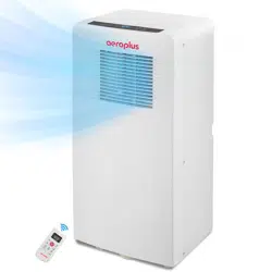
Instruction manual
Portable Air-conditioner
Toll Free:1-844-801-8880
Please read this user’s manual carefully to
ensure proper use, maintenance and installa-
tion
Model:
AAPC8RC1
AAPC10RC1

3
4
7
8
9
10
11
16
18
14
Table of contents
Safety Awareness
Specification
Name of Parts
Accessories
Appearance and Function of Control Panel
Appearance and Function of Remote Control
Installation Explanations
Operation Introduction
Troubleshooting
Maintenance Explanations

3
Specification
Rated Capacity
8000 Btu/h
Power Supply
1PH,115V~,60Hz
Rated Input
R32
760 W
Refrigerant
up to 350 sq.ft
Application area
≤55 dB(A)
Noise level
SACC
5,000 Btu/h
Model Name AAPC8RC1
10,000 Btu/h
1PH,115V~,60Hz
R32
920 W
up to 450 sq.ft
≤56 dB(A)
6,000 Btu/h
AAPC10RC1
Specification

4
Safety Awareness
The appliance is for indoor use only.
Do not use the unit on a socket under repairs or not installed properly.
5. Keep the unit upward while transport and storage, for the compressor
locates properly.
10.
Children should be supervised to ensure that they do not play with the
appliance.
1.
2.
Do not use the unit, follow these precautions:
3.
A: Near to source of fire.
B: An area where oil is likely to splash.
C: An area exposed to direct sunlight.
D: An area where water is likely to splash.
E: Near a bath, a laundry, a shower or a swimming pool.
4.
Never insert your fingers, rods into the air outlet. Take special care to
warn children of these dangers.
6.
Before cleaning the air-conditioner, always turn off or disconnect the
power supply.
7.
When moving the air-conditioner, always turn off and disconnect the power
supply, and move it slowly.
To avoid the possibility of fire disaster, the air-conditioner shall not be covered.the
product in a fire as it may explode.
8.
9.
All the air-conditioner sockets must comply with the local electric safety
requirements. If necessary, please check it for the requirements.
Safety Awareness
If the supply cord is damaged, it must be replaced by the manufacturer, its
service agent or similarly qualified persons in order to avoid a hazard.
11.
This appliance can be used by children aged from 8 years and above and
persons with reduced physical, sensory or mental capabilities or lack of
experience and knowledge if they have been given supervision or instruction
concerning use of the appliance in a safe way and understand the hazards
involved. Children shall not play with the appliance. Cleaning and user mainte-
nance shall not be made by children without supervision.
12.

5
Safety Awareness
Recycling.13.
This marking indicates that this product should not be
disposed with other household wastes throughout the EU. To
prevent possible harm to the environment or human health
from uncontrolled waste disposal, recycle it responsibly to
promote the sustainable reuse of material resources. To
return your used device, please use the return and collection
systems or contact the retailer where the product was
purchased. They can take this product for environmental safe
recycling.
14. Contact authorized service technician for repair or maintenance of this
unit.
15.
16.
Do not pull , deform . or modify the power supply cord , or immerse it in
water . Pulling or misuse of the power supply cord can result in damage
to the unit and cause electrical shock.
Compliance with national gas regulations shall be observed.
17.
Keep ventilation openings clear of obstruction.
18.
19.
Any person who is involved with working on or breaking into a refrigerant
circuit should hold a current valid certificate from an industry-accredited
assessment authority, which authorizes their competence to handle
refrigerants safely in accordance with an industry recognized assessment
specification.
Servicing shall only be performed as recommended by the equipment
manufacturer . Maintenance and repair requiring the assistance of other
skilled personnel shall be carried out under the supervision of the person
competent in the use of flammable refrigerants.
20.
Do not operate or stop the unit by inserting or pulling out Die power plug,
it may cause electric shock or fire due to heat generation .
21.
Unplug the unit if strange sounds, smell, or smoke comes from it.

6
— If any parts damage, please contact the dealer or a designated repair shop;
—In case of any damage, please turn off the air switch, disconnect the power
supply, and contact the dealer or a designated repair shop;
—To avoid the possibility of danger, if power cord is damaged, please turn off
the air switch and disconnect the power supply. It must be replaced from the
dealer or a designated repair shop.
—In any case, the power cord shall be firmly grounded.
Notes:
Safety Awareness
7
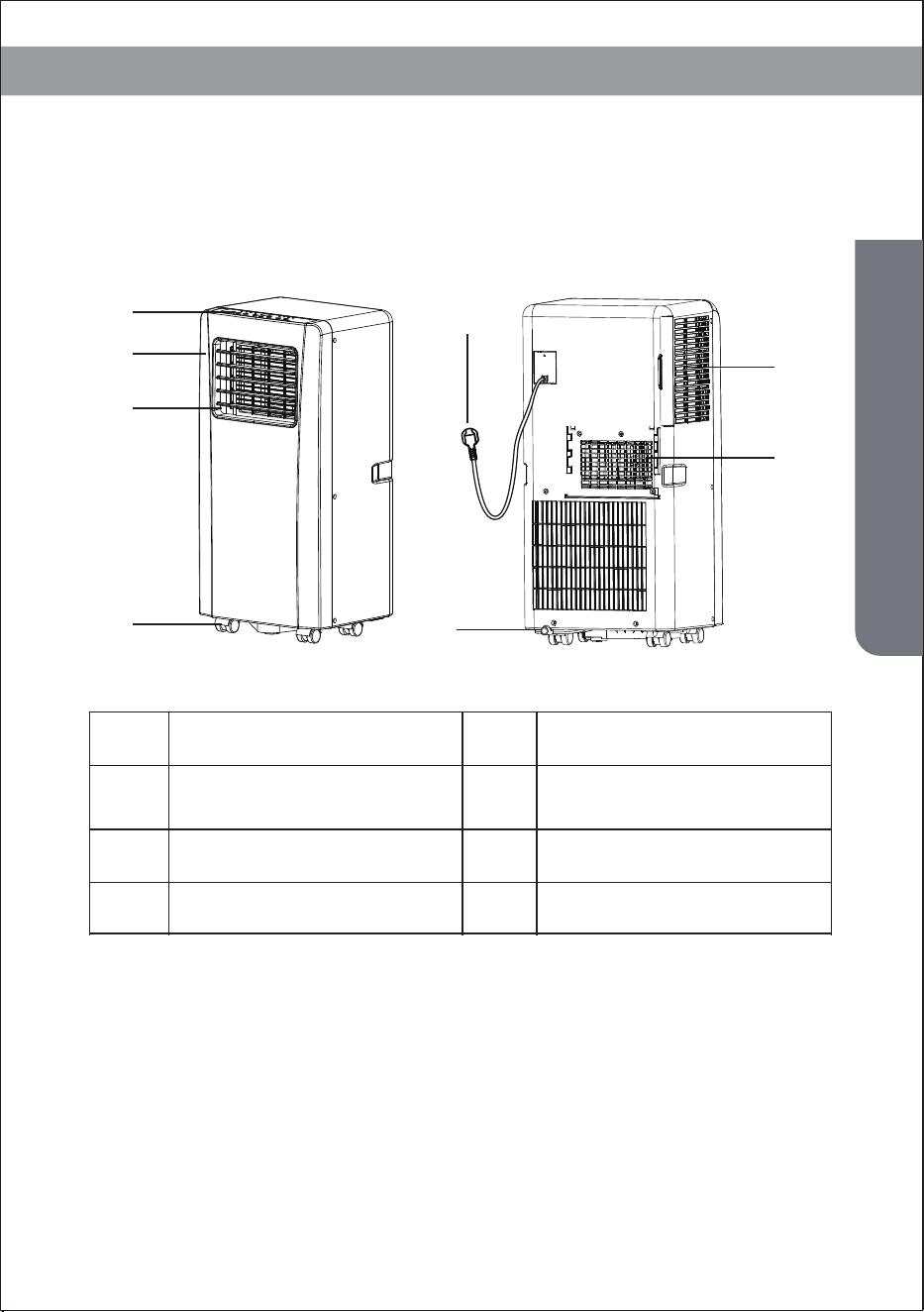
Name of Parts
Name of Parts
Control panel
1
Front cover
Louver
Castor
Power cord
Drainage outlet
Air inlet
Air outlet
1
2
3
4
5
6
7
8
2
3
7
8
4
6
5
8
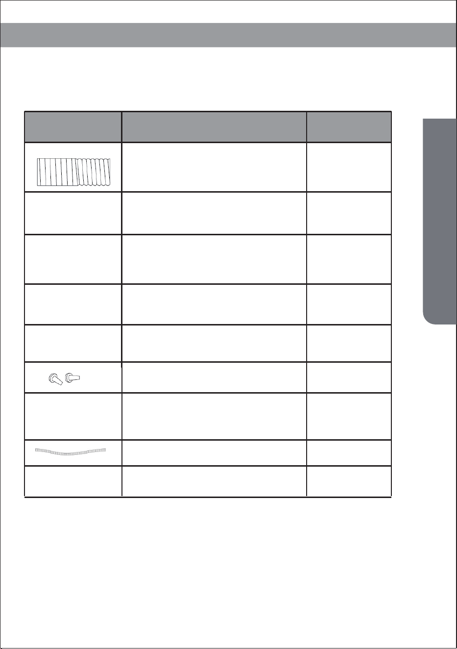
Accessories
After unpacking, please check whether the above-mentioned accessories
are included, and check their purposes in the installation introduction in
this manual.
Accessories
Part Description Quantity
Exhaust hose
Window Connector
Hoseing adaptor
Remote Controller
Window Kit
1
1
1
1
1 (optional)
2 (optional)
1 (optional)
1 (optional)
2 (optional)
Dowel
Air outlet
Water pipe
Batteries
9
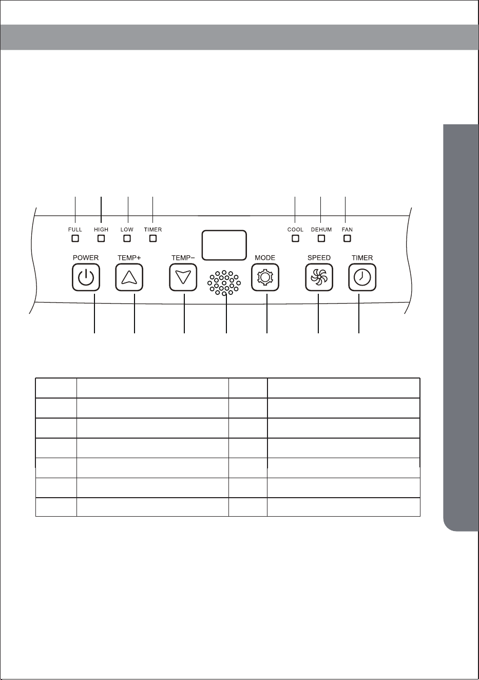
Appearance and Function of Control Panel
Appearance and Function of Control Panel
Cooling only model
1 2 3 4 5 6 7
A B C G D E F
Power on/off
Temperature up
Temperature down
Operation MODE
Water full
High fan speed
Low fan speed
Timer on/off
C
D
1
2
3
4
A
B
Power on/off
Temperature up
Cooling
Dehumidifying
Fan
5
6
7
E
F
Signal receiver
G
10
Appearance and Function of Control Panel
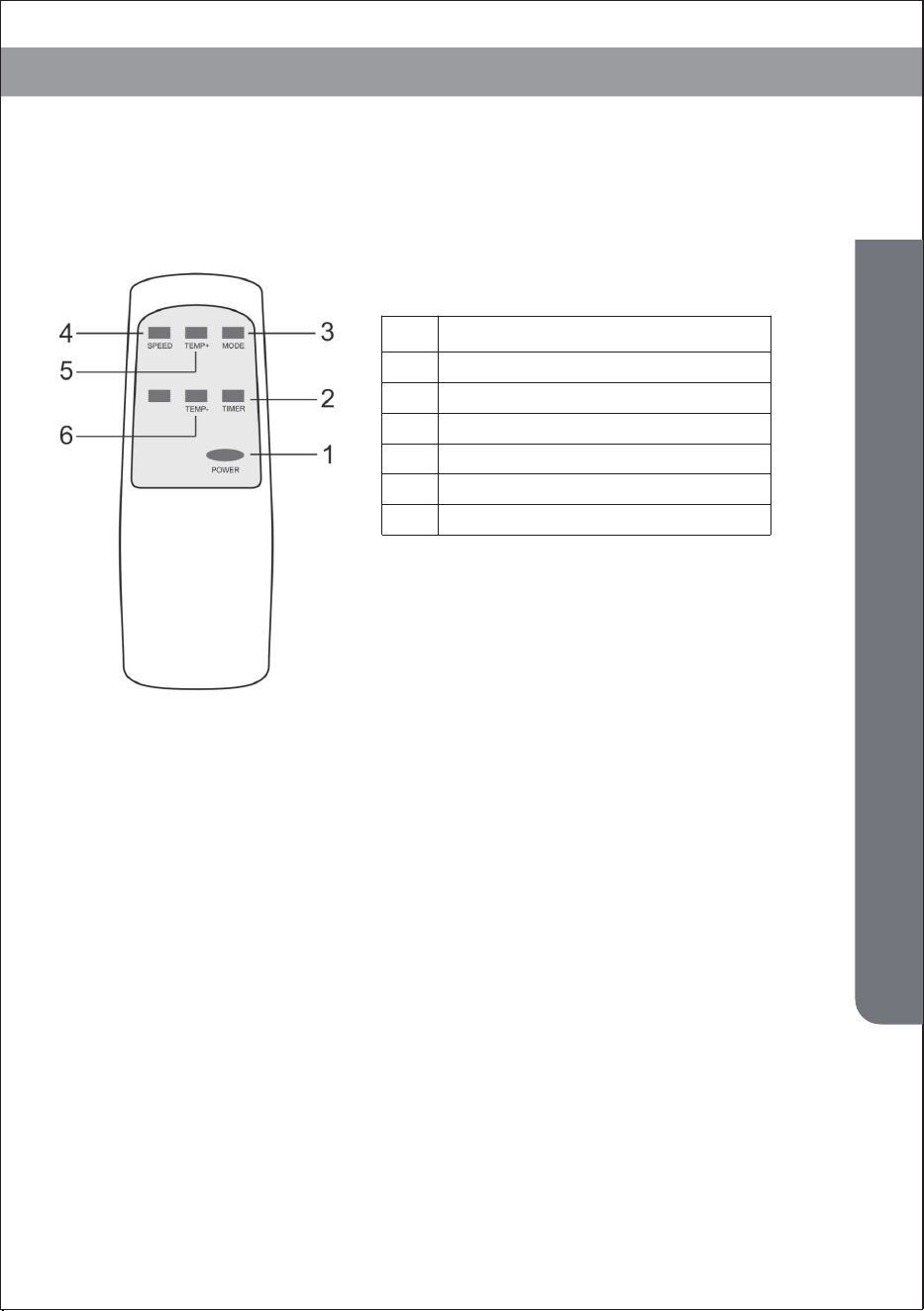
Appearance and Function of Remote Control
Notes:
- Do not drop the remote control.
- Do not place the remote control in a location exposed to direct sunlight.
Power on/off
Timer on/off
Operation MODE
Fan speed
Temperature up
Temperature down
1
2
3
4
5
6
11
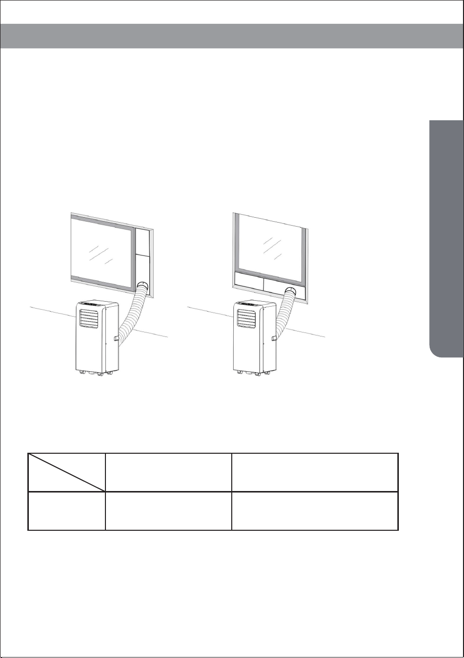
Operation Introduction
Before starting operations in this section:
1.Before using
-Operation temperature range:
Notice:
1)Find a place where there is power supply nearby.
2)As shown in Fig.2 and Fig.2a, install the exhaust hose, and adjust
the window position well.
3)Insert the power cord into an grounded AC115V/60Hz socket;
4)Press the POWER button to turn on the air-conditioner.
DB/WB(℉)
Maximum cooling Minimum cooling
95/75 64/54
Operation Introduction
Fig.2 Fig.2a

1.Power off memory (Auto-restart operation)
Check up whether the exhaust hose has been mounted properly.
Cautions for cooling and dehumidifying operations:
12
Operation Introduction
-When using functions on cooling and dehumidifying, keep an interval
of at least 3 minutes between each POWER.
-Power supply meets the requirements.
-The socket is for AC use.
-Do not share one socket with other appliances.
-Power supply is AC115V/60Hz
- If the unit loses power unexpectedly, it will restart with the
previous function settings when power is restored
2. Cooling operation
-Press the “Mode” button till the “Cool” icon appears.
-Press the “▲”or“ ▼”button to select a desired room temperature.
(60°F-90°F)
-Press the “Fan Speed” button to select wind speed.
3.Dehumidifying operation
Press the “Mode” button till the “Dehumidify” icon appears .
-Automatically set the selected temperature to current room tempera-
ture minus 2°F.
-Automatically set the fan motor to LOW wind speed.
4. Fan operation
-Press the “Mode” button till the “Fan” icon appears.
-Press the “Fan Speed” button to select wind speed.
5. Timer operation
Timer ON setting:
-When the air-conditioner is OFF, press the “Timer” button and select a
desired ON time through the temperature and time setting buttons.
-“Preset ON Time” is displayed on the operation panel.
-ON time can be regulated at any time in 0-24 hours. -Press the “Fan Speed”
button to select wind speed.
Timer OFF setting
-When the air-conditioner ON, press “Timer” button and select a desired
OFF time through the temperature and time setting buttons.
-“Preset OFF Time” is displayed on the operation panel.
-OFF time can be regulated at any time in 0-24 hours.

13
Operation Introduction
Fig.2
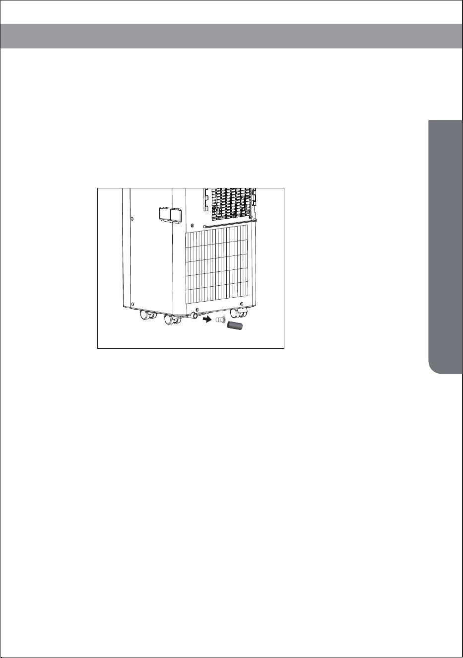
6. Water drainage
The inner water tray inside the air-conditioner has one water level safety
switches, it controls water level. When water level reaches an anticipated
height, the water full indicator lamp lights up. (If water splash motor is dam-
aged, when the water is full, please remove the rubber blockage at the bottom
of unit, and all water will drain outside.)
Water Full Alarm
- When you plan to leave this unit unused for a long time, please remove the
rubber blockage from the drainage hole at the bottom of unit, and connect a
drain hose to the lower fixing clip. All the water in the water tray will drain
outside.
- You can drain the water as the above when the unit working at the HEAT
mode.
- If water splash motor is damaged, continuous drainage can be used, and
under this condition, the water splash motor is not activated. The unit can also
work well.
If water splash motor is damaged, intermittent drainage can also be used.
Under this condition, when the water full indicator lamp lights up, please
connect a drain hose to the lower fixing clip, then all the water in the water tray
will be drained outside. The unit can also work well.
Continuous Drainage
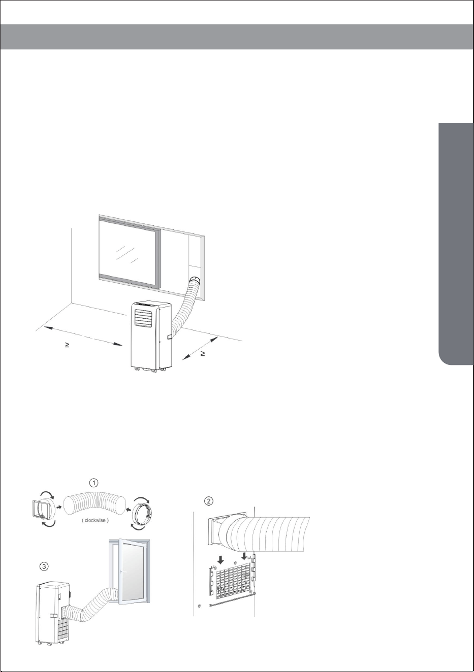
Fig.3
14
Installation Explanations
Installation Explanations
Installation Explanations:
-A removal air-conditioner shall be installed in the flat and empty place all
around. Don’t block the air outlet, and the required distance around
should be at least 30cm. (See Fig.3)
-Should not be installed in wet location, such as the laundry room.
-Socket wiring should be in accordance with the local electric safety
requirements .
2.Introduction to Exhaust Hose Installation
A) Temporary installation
1. Twist both ends of the exhaust hose into the Hose Connector.
2. Insert the fixing clip of the housing adaptor into the openings at back of
the air conditioner (see Fig.4).
3. Put the other end of the exhaust hose to the near windowsill.
11.8 inch
11.8 inch
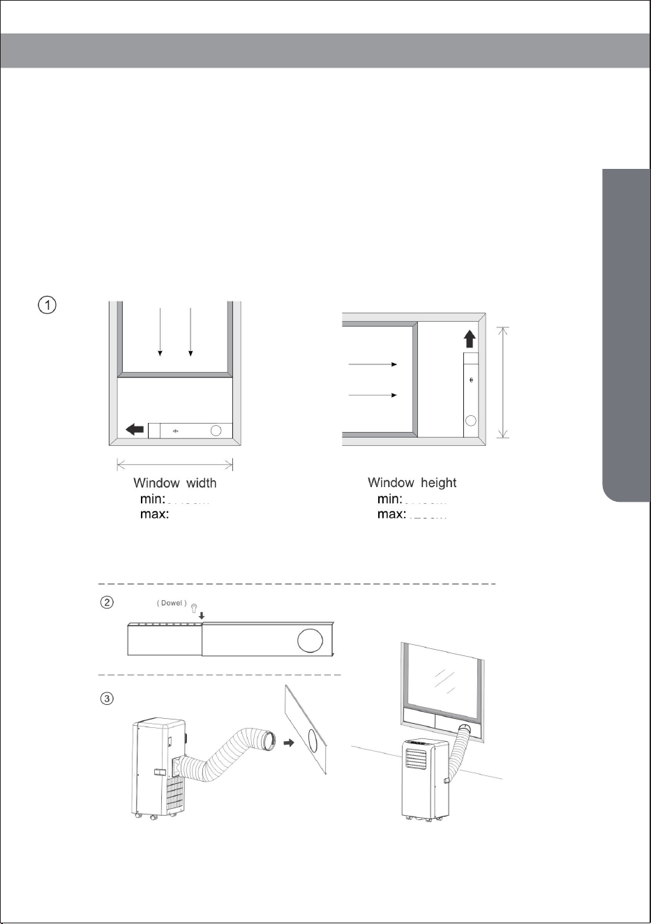
B) Window Slider Kit Installation
The installation manner of window slider kit is mostly in “horizontal” or
“vertical”. As shown Fig.5 and Fig.5a, check the min. and max. size of the
window before the installation.
1. Install the window kit on the window;
2. Adjust the length of the window slider kit according to the window width
or height, and fix it with the dowel;
3. Insert the window connector hose to the hole of the window kit(Fig.5b).
Fig.5 Fig.5a
Fig.5b
15
Installation Explanations
27 inch 27 inch
48 inch48 inch
Water Full Alarm Function
The inner water tray in the air-conditioner has one water level safety
switches, it controls water level. When water level reaches an anticipated
height, the water full indicator lamp lights up. (If water splash motor is
damaged, when the water is full, please remove the rubber blockage at the
bottom of unit, and all water will drain outside.)
Fig.6
16
Maintenance Explanations
17
Maintenance Explanations
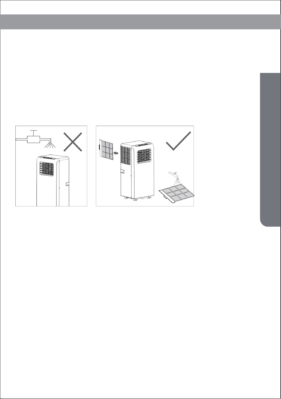
1) Before cleaning, be sure to disconnect the unit from any electric
supply outlet;
Declaration:
2) Do not use gasoline or other chemicals to clean the unit;
3) Do not wash the unit directly;
4) If the conditioner is damaged, please contact the dealer or repair shop.
1. Air Filter
-If the air filter becomes clogged with dust/dirt, the air filter should be
cleaned once every two weeks.
-Dismounting
Open the air inlet grille and take off air filter.
-Cleaning
Clean the air filter with neural detergent in lukewarm(104℉)and dry it up in
the shade.
Maintenance Explanations
Mounting
Putting the air filter into the inlet grille, replace the components as they were.
First clean the surface with a neutral detergent and wet cloth, and then wipe it
with a dry cloth.
2.Clean the Air-conditioner Surface
18
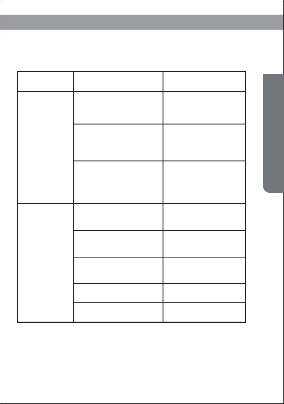
Troubleshooting
1.Unit does
not start
when press-
ing on/off
button
2. Not cool
enough
Possible CausesTroubles Suggested Remedies
- Water full indicator lamp
blinks, and water tank is full.
- Room temperature is higher
than the setting temperature.
(Electric heating mode)
- Room temperature is lower than
the setting temperature. (Cooling
mode)
Reset the temperature
- The doors or windows are
not closed.
Make sure all the windows
and doors are closed.
- There are heat sources
inside the room.
Remove the heat sources if
possible
Connect or clean the exhaust
air hose.
Reset the temperature
- Exhaust air hose is not
connected or blocked.
- Temperature setting is too high.
- Air inlet is blocked. Clean the air inlet.
Dump the water out of the
water tank.
Reset the temperature
Troubleshooting
19
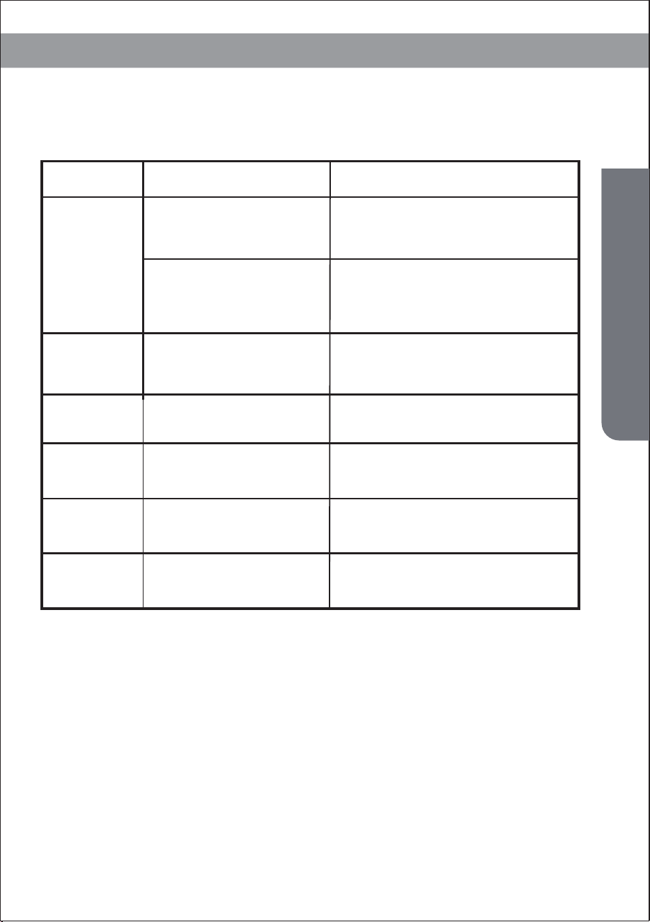
Troubleshooting
3. Noisy
4. E0 Code
5. E2 Code
6. E3 Code
Possible CausesTroubles
Suggested Remedies
- The ground is not level or
not flat enough
- The sound comes from
the flowing of the
refrigerant inside the air
conditioner
Room temperature
sensor failed
Go to service center
Water tray full when
cooling
Take off rubber stopper and
empty the water.
Go to service center
Evaporator temperature
sensor failed
7. E3 Code
Replace evaporator
temperature sensor
Evaporator temperature
sensor failed
8. E4 Code
Please empty the water tray.
Water tray full when heating
Note: The real products may look different.
Place the unit on a flat, level ground
if possible
It is normal.
Troubleshooting