
Visit our website at: http://www.harborfreight.com
Email our technical support at: [email protected]
70952
12” SHOP PRESS
BRAKE ATTACHMENT
TM
Owner’s Manual & Safety Instructions
Save This Manual Keep this manual for the safety warnings and precautions, assembly,
operating, inspection, maintenance and cleaning procedures. Write the product’s serial number in the
back of the manual near the assembly diagram (or month and year of purchase if product has no number).
Keep this manual and the receipt in a safe and dry place for future reference. 24f
When unpacking, make sure that the product is intact
and undamaged. If any parts are missing or broken,
please call 1-888-866-5797 as soon as possible.
Copyright
©
2024 by Harbor Freight Tools
®
. All rights reserved.
No portion of this manual or any artwork contained herein may be reproduced in
any shape or form without the express written consent of Harbor Freight Tools.
Diagrams within this manual may not be drawn proportionally. Due to continuing
improvements, actual product may differ slightly from the product described herein.
Tools required for assembly and service may not be included.
Read this material before using this product.
Failure to do so can result in serious injury.
SAVE THIS MANUAL.

Page 2 For technical questions, please call 1-888-866-5797. 70952
WARNING SYMBOLS AND DEFINITIONS
This is the safety alert symbol. It is used to alert you to
potential personal injury hazards. Obey all safety messages
that follow this symbol to avoid possible injury or death.
Indicates a hazardous situation which, if not avoided,
will result in death or serious injury.
Indicates a hazardous situation which, if not avoided,
could result in death or serious injury.
Indicates a hazardous situation which, if not avoided,
could result in minor or moderate injury.
Addresses practices not related to personal injury.
IMPORTANT SAFETY INFORMATION
1. Study, understand, and follow all instructions
before operating the device.
2. Do not exceed rated capacity.
3. Ensure load is secured to the device.
4. To be used only with the following PASE: Shop Press.
5. Failure to heed these markings may result in
personal injury and/or property damage.
6. Release load-locking devices (if
employed) slowly and carefully.
7. No alterations shall be made to this product.
8. Work area safety
a. Keep work area clean and well lit. Cluttered
or dark areas invite accidents.
b. Keep children and bystanders away while
operating the tool. Distractions can cause
you to lose control.
9. Personal safety
a. Stay alert, watch what you are doing and
use common sense when operating the tool.
Do not use while you are tired or under the
influence of drugs, alcohol or medication.
A moment of inattention while operating the
tool may result in serious personal injury.
b. Wear ANSI-approved safety goggles and
heavy-duty work gloves during use.
c. Do not overreach. Keep proper footing and
balance at all times. This enables better
control of the tool in unexpected situations.
d. Dress properly. Do not wear loose clothing or
jewelry. Keep your hair, clothing and gloves
away from moving parts. Loose clothes, jewelry
or long hair can be caught in moving parts.
10. Tool use and care
a. Do not force the tool. Use the correct tool for your
application. The correct tool will do the job better
and safer at the rate for which it was designed.
b. Store idle tools out of the reach of children and
do not allow persons unfamiliar with the tool or
these instructions to operate the tool. Tools are
dangerous in the hands of untrained users.
c. Maintain tools. Check for misalignment or
binding of moving parts, breakage of parts
and any other condition that may affect
the tool’s operation. If damaged, have the
tool repaired before use. Many accidents
are caused by poorly maintained tools.
d. Use the tool in accordance with these
instructions, taking into account the working
conditions and the work to be performed. Use
of the tool for operations different from those
intended could result in a hazardous situation.
11. Service
a. Have your tool serviced by a qualified
repair person using only identical
replacement parts. This will ensure that
the safety of the tool is maintained.
12. Do not move workpiece while compressed.
13. Release load before service or maintenance.

Page 3For technical questions, please call 1-888-866-5797.70952
14. STOP and release compression if you suspect
imminent structural failure. If safe, inspect
thoroughly and reposition before proceeding.
15. Do not compress springs or other elastic
objects. They could disengage hazardously.
16. This product is not a toy. Keep it
out of reach of children.
17. Maintain labels and nameplates on
the tool. These carry important safety
information. If unreadable or missing, contact
Harbor Freight Tools for a replacement.
18. The warnings, precautions, and instructions
discussed in this manual cannot cover all possible
conditions and situations that may occur. The
operator must understand that common sense and
caution are factors, which cannot be built into this
product, but must be supplied by the operator.
SAVE THESE INSTRUCTIONS.
Specifications
Aluminum
3/16″ thick x 12″ wide
5/16″ thick x 6″ wide
3/8″ thick x 3″ wide
Mild Steel
3/16″ thick x 12″ wide
1/4″ thick x 6″ wide
5/16″ thick x 3″ wide
Stainless
1/8″ thick x 12″ wide
3/16″ thick x 6″ wide
1/4″ thick x 3″ wide
Bend Angle up to 90°
Shop Press Capacity 20 ton (max)
Page 4 For technical questions, please call 1-888-866-5797. 70952
Assembly Instructions
Read the ENTIRE IMPORTANT SAFETY INFORMATION section at the beginning of this document
including all text under subheadings therein before set up or use of this product.
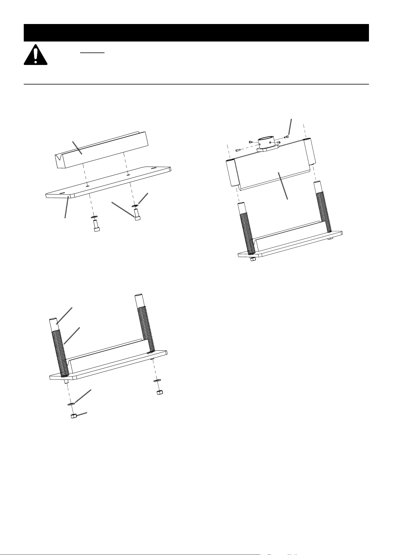
Assembly
1. Place Lower Die (5) onto Base Plate (6).
2. Place Washes (9) and Screws (10)
into Base Plate and Lower Die.
3. Tighten Screws.
Lower Die (5)
Screw (10)
Washer (9)
Base Plate (6)
4. Place Side Posts (3) into Base Plate.
5. Place Washers (7) and Nuts (8)
onto Side Posts thread.
6. Tighten Nuts.
7. Slide Springs (4) over Side Posts.
Side Post (3)
Washer (7)
Nut (8)
Spring (4)
8. Place Upper die (2) onto Side Posts.
9. Place Screws (1) into Upper Die. Do not tighten.
Upper Die (2)
Screw (1)

Page 5For technical questions, please call 1-888-866-5797.70952
Operating Instructions
Read the ENTIRE IMPORTANT SAFETY INFORMATION section at the beginning of this
manual including all text under subheadings therein before set up or use of this product.
Workpiece and Work Area Set Up
1. Designate a work area that is clean and well-lit.
The work area must not allow access by children
or pets to prevent distraction and injury.
2. Secure loose workpieces using a vise or clamps
(not included) to prevent movement while working.
3. There must not be hazardous objects, such
as utility lines or foreign objects, nearby that
will present a hazard while working.
4. You must use personal safety equipment including,
but not limited to, ANSI-approved eye and hearing
protection, as well as heavy-duty work gloves.
General Operating Instructions
Note: Before use, it is necessary that the tool is
installed to a securely mounted hydraulic press.
Note: Do not use with shop press
rated for more than 20 tons.
1. Place tool onto shop press.
2. Lower hydraulic ram into cup of Upper Die (2).
3. Tighten screws (1).
Angle Bending
1. Mark the workpiece where you
want to bend the material.
2. Place the material between Dies.
3. Align the bending mark with the
front edge of the Upper Die.
4. Gently draw down hydraulic ram until
material is bent to desired angle.
Maintenance and Servicing
Procedures not specifically explained in this manual must
be performed only by a qualified technician.
TO PREVENT SERIOUS INJURY FROM TOOL FAILURE:
Do not use damaged equipment. If abnormal noise or vibration occurs,
have the problem corrected before further use.
Cleaning, Maintenance, and Lubrication
1. BEFORE EACH USE, inspect the general
condition of the tool.
Check for loose hardware, misalignment
or binding of moving parts,
cracked or broken parts, and any other
condition that may affect its safe operation.
2. Regularly grease all moving parts.
3. AFTER USE, wipe external surfaces
of the tool with clean cloth.

Page 6 For technical questions, please call 1-888-866-5797. 70952
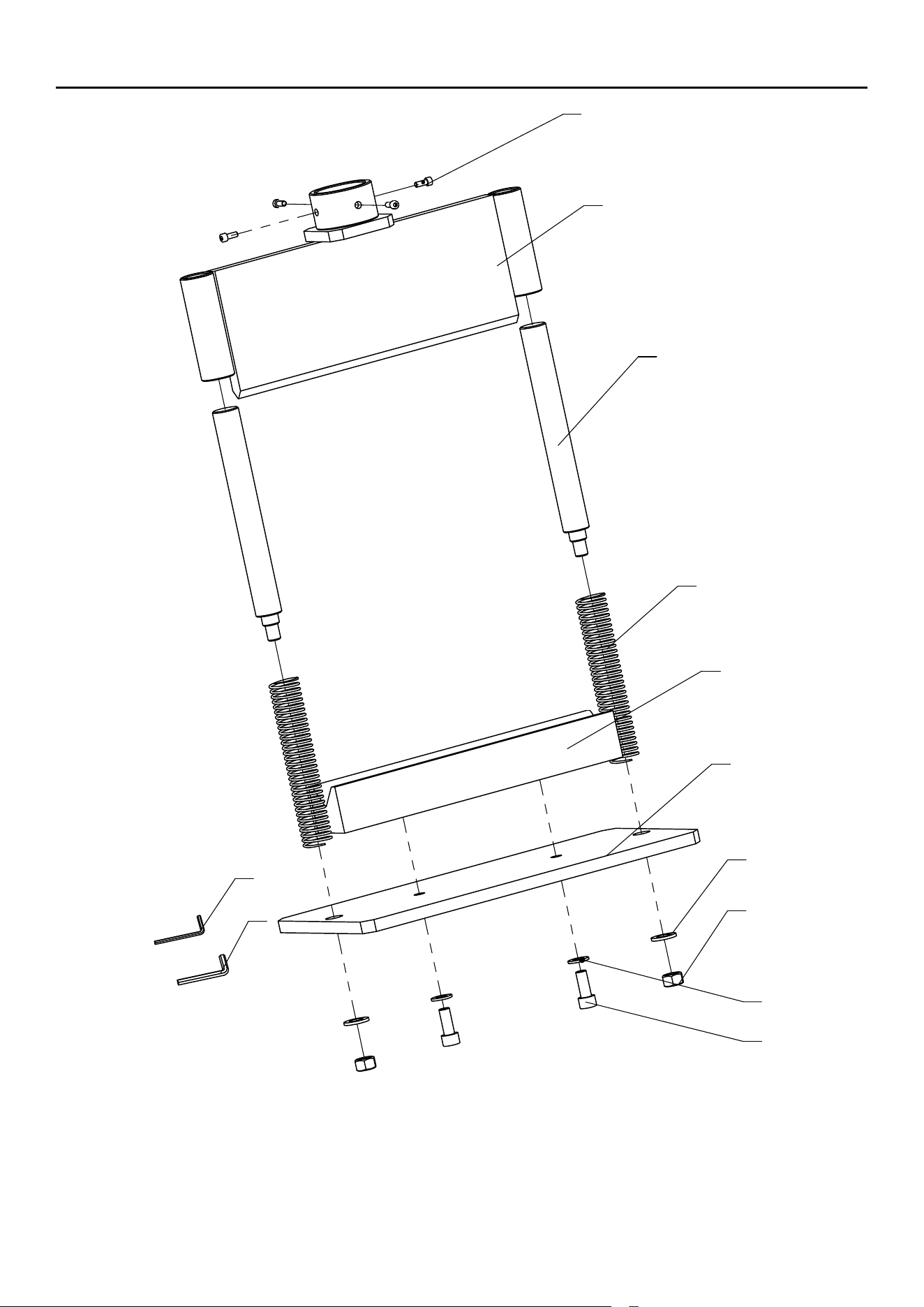
Parts List and Assembly Diagram
Parts List
Part Description Qty
1 M8 x 20 Screw 4
2 Upper Die 1
3 Slide Post 2
4 Release Spring 2
5 Lower Die 1
6 Base Plate 1
7 M12 Washer 2
8 M12 Nut 2
9 M10 Washer 2
10 M10 x 20 Screw 2
11 Hex Key S=6 1
12 Hex Key S=8 1
PLEASE READ THE FOLLOWING CAREFULLY
THE MANUFACTURER AND/OR DISTRIBUTOR HAS PROVIDED THE PARTS LIST AND ASSEMBLY
DIAGRAM IN THIS MANUAL AS A REFERENCE TOOL ONLY. NEITHER THE MANUFACTURER
OR DISTRIBUTOR MAKES ANY REPRESENTATION OR WARRANTY OF ANY KIND TO THE
BUYER THAT HE OR SHE IS QUALIFIED TO MAKE ANY REPAIRS TO THE PRODUCT, OR
THAT HE OR SHE IS QUALIFIED TO REPLACE ANY PARTS OF THE PRODUCT. IN FACT, THE
MANUFACTURER AND/OR DISTRIBUTOR EXPRESSLY STATES THAT ALL REPAIRS AND PARTS
REPLACEMENTS SHOULD BE UNDERTAKEN BY CERTIFIED AND LICENSED TECHNICIANS,
AND NOT BY THE BUYER. THE BUYER ASSUMES ALL RISK AND LIABILITY ARISING OUT OF
HIS OR HER REPAIRS TO THE ORIGINAL PRODUCT OR REPLACEMENT PARTS THERETO,
OR ARISING OUT OF HIS OR HER INSTALLATION OF REPLACEMENT PARTS THERETO.
Record Product’s Serial Number Here:
Note: If product has no serial number, record month and year of purchase instead.
Note: Some parts are listed and shown for illustration purposes only, and are not available
individually as replacement parts. Specify UPC 193175522009 when ordering parts.
Page 7For technical questions, please call 1-888-866-5797.70952
Assembly Diagram
7
3
2
4
1
6
10
8
5
9
11
12

26677 Agoura Road • Calabasas, CA 91302 • 1-888-866-5797
TM
Limited 90 Day Warranty
Harbor Freight Tools Co. makes every effort to assure that its products meet high quality and durability
standards, and warrants to the original purchaser that this product is free from defects in materials
and workmanship for the period of 90 days from the date of purchase. This warranty does not apply to
damage due directly or indirectly, to misuse, abuse, negligence or accidents, repairs or alterations outside
our facilities, criminal activity, improper installation, normal wear and tear, or to lack of maintenance.
We shall in no event be liable for death, injuries to persons or property, or for incidental, contingent,
special or consequential damages arising from the use of our product. Some states do not allow the
exclusion or limitation of incidental or consequential damages, so the above limitation of exclusion
may not apply to you. THIS WARRANTY IS EXPRESSLY IN LIEU OF ALL OTHER WARRANTIES,
EXPRESS OR IMPLIED, INCLUDING THE WARRANTIES OF MERCHANTABILITY AND FITNESS.
To take advantage of this warranty, the product or part must be returned to us with transportation charges
prepaid. Proof of purchase date and an explanation of the complaint must accompany the merchandise.
If our inspection verifies the defect, we will either repair or replace the product at our election or we may
elect to refund the purchase price if we cannot readily and quickly provide you with a replacement. We will
return repaired products at our expense, but if we determine there is no defect, or that the defect resulted
from causes not within the scope of our warranty, then you must bear the cost of returning the product.
This warranty gives you specific legal rights and you may also
have other rights which vary from state to state.
