
Visit our website at: http://www.harborfreight.com
email our technical support at: [email protected]
93799
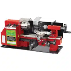
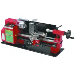
7" X 12"
MINI LATHE
Owner’s Manual & Safety Instructions
Save This Manual Keep this manual for the safety warnings and precautions, assembly,
operating, inspection, maintenance and cleaning procedures. Write the product’s serial number in the
back of the manual near the assembly diagram (or month and year of purchase if product has no number).
Keep this manual and the receipt in a safe and dry place for future reference. 24c
When unpacking, make sure that the product is intact
and undamaged. If any parts are missing or broken,
please call 1-888-866-5797 as soon as possible.
Copyright
©
2024 by Harbor Freight Tools
®
. All rights reserved.
No portion of this manual or any artwork contained herein may be reproduced in
any shape or form without the express written consent of Harbor Freight Tools.
Diagrams within this manual may not be drawn proportionally. Due to continuing
improvements, actual product may differ slightly from the product described herein.
Tools required for assembly and service may not be included.
read this material before using this product.
Failure to do so can result in serious injury.
SaVe tHiS ManuaL.
Page 2 For technical questions, please call 1-888-866-5797. 93799
SaFety OperatiOn MaintenanceSetup
table of contents
Safety ......................................................... 2
Specifications ............................................. 6
Setup .......................................................... 8
Operating Instructions ............................... 12
Maintenance .............................................. 14
Parts List.................................................... 18
Warranty .................................................... 24
WarninG SyMBOLS anD DeFinitiOnS
This is the safety alert symbol. It is used to alert you to potential
personal injury hazards. Obey all safety messages that
follow this symbol to avoid possible injury or death.
Indicates a hazardous situation which, if not avoided,
will result in death or serious injury.
Indicates a hazardous situation which, if not avoided,
could result in death or serious injury.
Indicates a hazardous situation which, if not avoided,
could result in minor or moderate injury.
Addresses practices not related to personal injury.
iMpOrtant SaFety inFOrMatiOn
General tool Safety Warnings
read all safety warnings and instructions.
Failure to follow the warnings and instructions may result in electric shock, fire and/or serious injury.
Save all warnings and instructions for future reference.
1. KEEP GUARDS IN PLACE and in working order.
2. REMOVE ADJUSTING KEYS AND
WRENCHES. Form habit of checking to
see that keys and adjusting wrenches are
removed from tool before turning it on.
3. KEEP WORK AREA CLEAN.
Cluttered areas and benches invite accidents.
4. DON’T USE IN DANGEROUS ENVIRONMENT.
Don’t use power tools in damp or wet locations,
or expose them to rain. Keep work area well lighted.
5. KEEP CHILDREN AWAY. All visitors should
be kept safe distance from work area.
6. MAKE WORKSHOP KID PROOF with padlocks,
master switches, or by removing starter keys.
7. DON’T FORCE TOOL. It will do the job better
and safer at the rate for which it was designed.
8. USE RIGHT TOOL. Don’t force tool or attachment
to do a job for which it was not designed.

Page 3For technical questions, please call 1-888-866-5797. 93799
SaFetyOperatiOnMaintenance Setup
table a: recOMMenDeD MiniMuM Wire GauGe
FOr eXtenSiOn cOrDS
(120 VOLt)
naMepLate
aMpereS
(at full load)
eXtenSiOn cOrD
LenGtH
25′ 50′ 100′ 150′
0 – 6 18 16 16 14
6.1 – 10 18 16 14 12
10.1 – 12 16 16 14 12
12.1 – 16 14 12 Do not use.
9. USE PROPER EXTENSION CORD. Make sure your
extension cord is in good condition. When using
an extension cord, be sure to use one heavy
enough to carry the current your product will draw.
An undersized cord will cause a drop in line voltage
resulting in loss of power and overheating.
Table A shows the correct size to use depending
on cord length and nameplate ampere rating.
If in doubt, use the next heavier gauge.
The smaller the gauge number, the heavier the cord.
10. WEAR PROPER APPAREL. Do not wear
loose clothing, gloves, neckties, rings, bracelets,
or other jewelry which may get caught in moving
parts. Nonslip footwear is recommended.
Wear protective hair covering to contain long hair.
11. ALWAYS USE SAFETY GLASSES. Also use
face or dust mask if cutting operation is dusty.
Everyday eyeglasses only have impact resistant
lenses, they are NOT safety glasses.
12. SECURE WORK. Use clamps or a vise to
hold work when practical. It’s safer than using your
hand and it frees both hands to operate tool.
13. DON’T OVERREACH.
Keep proper footing and balance at all times.
14. MAINTAIN TOOLS WITH CARE. Keep
tools sharp and clean for best and safest
performance. Follow instructions for
lubricating and changing accessories.
15. DISCONNECT TOOLS before servicing;
when changing accessories, such as
blades, bits, cutters, and the like.
16. REDUCE THE RISK OF UNINTENTIONAL
STARTING. Make sure switch is in
off position before plugging in.
17. USE RECOMMENDED ACCESSORIES.
Consult the owner’s manual for recommended
accessories. The use of improper accessories
may cause risk of injury to persons.
18. NEVER STAND ON TOOL.
Serious injury could occur if the tool is tipped or
if the cutting tool is unintentionally contacted.
19. CHECK DAMAGED PARTS. Before further use
of the tool, a guard or other part that is damaged
should be carefully checked to determine that
it will operate properly and perform its intended
function – check for alignment of moving parts,
binding of moving parts, breakage of parts,
mounting, and any other conditions that may
affect its operation. A guard or other part that is
damaged should be properly repaired or replaced.
20. DIRECTION OF FEED.
Feed work into a blade or cutter against the
direction of rotation of the blade or cutter only.
21. NEVER LEAVE TOOL RUNNING UNATTENDED.
TURN POWER OFF. Don’t leave tool
until it comes to a complete stop.

Page 4 For technical questions, please call 1-888-866-5797. 93799
SaFety OperatiOn MaintenanceSetup
Grounding instructions
tO preVent eLectric SHOcK anD DeatH FrOM incOrrect
GrOunDinG Wire cOnnectiOn reaD anD FOLLOW tHeSe inStructiOnS:
110-120 Vac Grounded tools: tools with three prong plugs
1. In the event of a malfunction or breakdown,
grounding provides a path of least resistance for
electric current to reduce the risk of electric shock.
This tool is equipped with an electric cord having an
equipment-grounding conductor and a grounding
plug. The plug must be plugged into a matching
outlet that is properly installed and grounded in
accordance with all local codes and ordinances.
2. Do not modify the plug provided – if it will
not fit the outlet, have the proper outlet
installed by a qualified electrician.
3. Improper connection of the equipment-grounding
conductor can result in a risk of electric shock.
The conductor with insulation having an outer
surface that is green with or without yellow
stripes is the equipment-grounding conductor.
If repair or replacement of the electric cord or
plug is necessary, do not connect the equipment-
grounding conductor to a live terminal.
4. Check with a qualified electrician or service
personnel if the grounding instructions are
not completely understood, or if in doubt as
to whether the tool is properly grounded.
5. Use only 3-wire extension cords that
have 3-prong grounding plugs and 3-pole
receptacles that accept the tool’s plug.
6. Repair or replace damaged or
worn cord immediately.
Grounding
pin
125 Vac 3-prong plug and Outlet
(for up to 125 Vac and up to 15 a)
7. This tool is intended for use on a circuit that has
an outlet that looks like the one illustrated above in
125 Vac 3-prong plug and Outlet. The tool has
a grounding plug that looks like the plug illustrated
above in 125 Vac 3-prong plug and Outlet.
8. The outlet must be properly installed and grounded
in accordance with all codes and ordinances.
9. Do not use an adapter to connect
this tool to a different outlet.
Lathe Safety Warnings
For your Own Safety read instruction
Manual Before Operating Lathe
1. Wear eye protection.
2. Do not wear gloves, necktie, or loose clothing.
3. Tighten all locks before operating.
4. Rotate workpiece by hand before applying power.
5. Rough out workpiece before installing on faceplate.
6. Do not mount split workpiece or one containing knot.
7. Use lowest speed when starting new workpiece.
8. DO nOt Operate WitH any GuarD
DiSaBLeD, DaMaGeD, Or reMOVeD. Moving
guards must move freely and close instantly.
9. The use of accessories or attachments not
recommended by the manufacturer may
result in a risk of injury to persons.
10. When servicing use only identical replacement parts.
11. Do not depress the spindle lock when
starting or during operation.
12. Only use safety equipment that has been approved
by an appropriate standards agency. Unapproved
safety equipment may not provide adequate
protection. Eye protection must be ANSI-approved
and breathing protection must be NIOSH-approved
for the specific hazards in the work area.

Page 5For technical questions, please call 1-888-866-5797. 93799
SaFetyOperatiOnMaintenance Setup
13. Stay alert, watch what you are doing and use
common sense when operating a power tool.
Do not use a power tool while you are tired or
under the influence of drugs, alcohol or medication.
A moment of inattention while operating power
tools may result in serious personal injury.
14. Industrial applications must follow OSHA guidelines.
15. Maintain labels and nameplates on the tool.
These carry important safety information.
If unreadable or missing, contact
Harbor Freight Tools for a replacement.
16. Avoid unintentional starting.
Prepare to begin work before turning on the tool.
17. People with pacemakers should consult their
physician(s) before use. Electromagnetic fields in
close proximity to heart pacemaker could cause
pacemaker interference or pacemaker failure.
18. The warnings, precautions, and instructions
discussed in this instruction manual cannot cover all
possible conditions and situations that may occur.
It must be understood by the operator that
common sense and caution are factors
which cannot be built into this product,
but must be supplied by the operator.
Vibration Safety
This tool vibrates during use. Repeated or
long-term exposure to vibration may cause
temporary or permanent physical injury,
particularly to the hands, arms and shoulders.
To reduce the risk of vibration-related injury:
1. Anyone using vibrating tools regularly or for an
extended period should first be examined by a
doctor and then have regular medical check-ups
to ensure medical problems are not being caused
or worsened from use. Pregnant women or
people who have impaired blood circulation to
the hand, past hand injuries, nervous system
disorders, diabetes, or Raynaud’s Disease should
not use this tool. If you feel any medical or
physical symptoms related to vibration (such as
tingling, numbness, and white or blue fingers),
seek medical advice as soon as possible.
2. Do not smoke during use. Nicotine reduces
the blood supply to the hands and fingers,
increasing the risk of vibration-related injury.
3. Use tools with the lowest vibration when there
is a choice between different processes.
4. Include vibration-free periods each day of work.
5. Grip workpiece as lightly as possible (while still
keeping safe control of it). Let the tool do the work.
6. To reduce vibration, maintain the tool as
explained in this manual. If any abnormal
vibration occurs, stop use immediately.
SaVe tHeSe inStructiOnS.
Page 6 For technical questions, please call 1-888-866-5797. 93799
SaFety OperatiOn MaintenanceSetup
Specifications
Motor 120 VAC / 60 Hz / 3/4 HP
Speed Ranges
0 - 1100 RPM (Low)
0 - 2500 RPM (High)
Drive Gear and Belt
Swing Over Bed 7"
Distance Between Centers 12"
Spindle Bore 3/4"
Quill Travel 2"
Cross Slide Travel 2-3/4"
Cross Slide Swing 4-1/2"
Work Tolerance .005"
Bed Dimensions 19-7/8" L x 3-1/4" W
Saddle Travel 6-7/8"
Compound Travel 2-7/8"
Speed Ranges
0-1100 (low)
0-2500 (high)
Chuck Dimensions 80mm, 3 Jaw
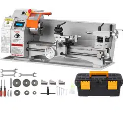
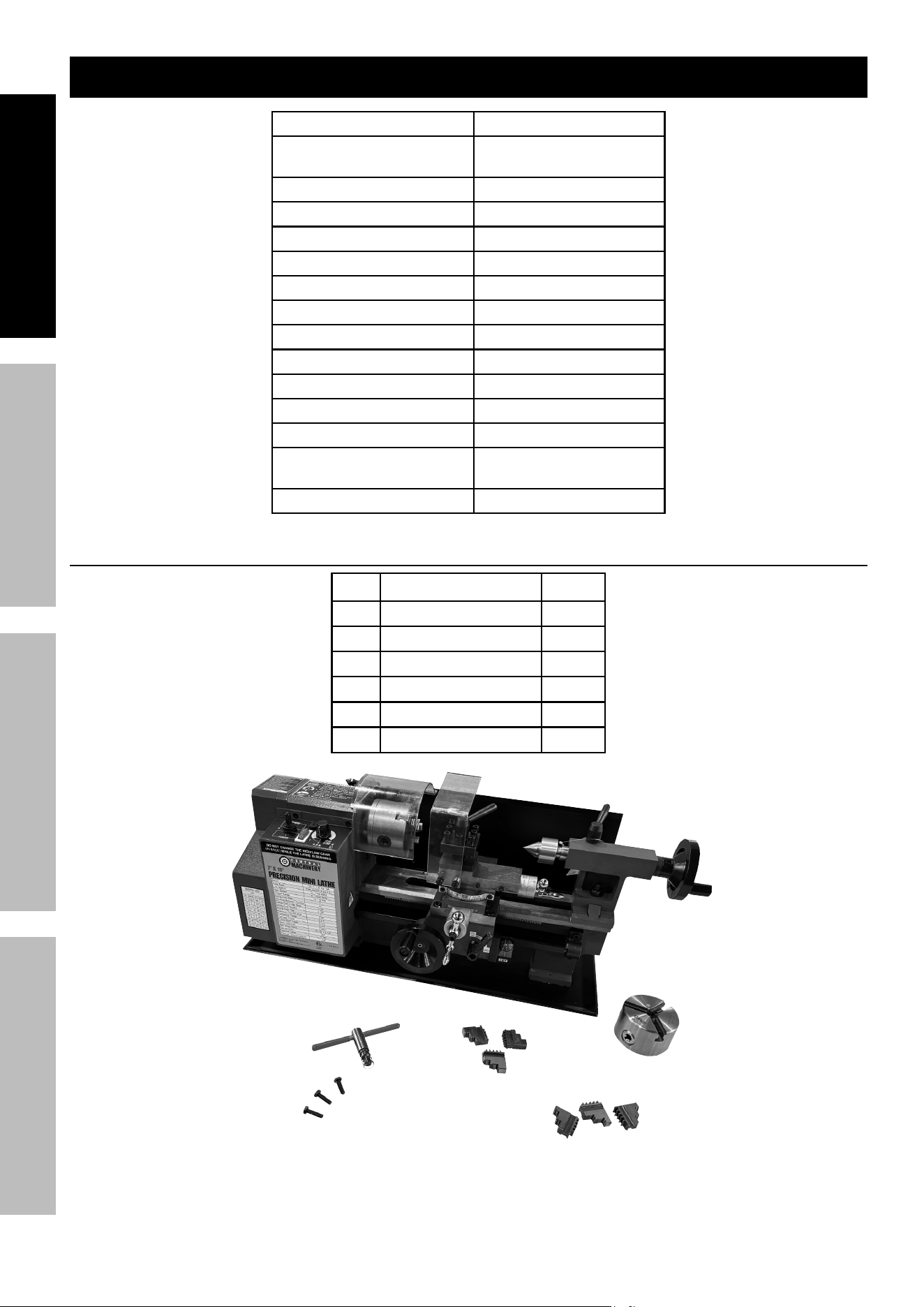
Main components
Description Qty
A Lathe 1
B Chuck Key 1
C External Jaws 3
D Chuck 1
E Chuck Set Screws 3
F Internal Jaws 3
a
B
e
c
F
D
Page 7For technical questions, please call 1-888-866-5797. 93799
SaFetyOperatiOnMaintenance Setup
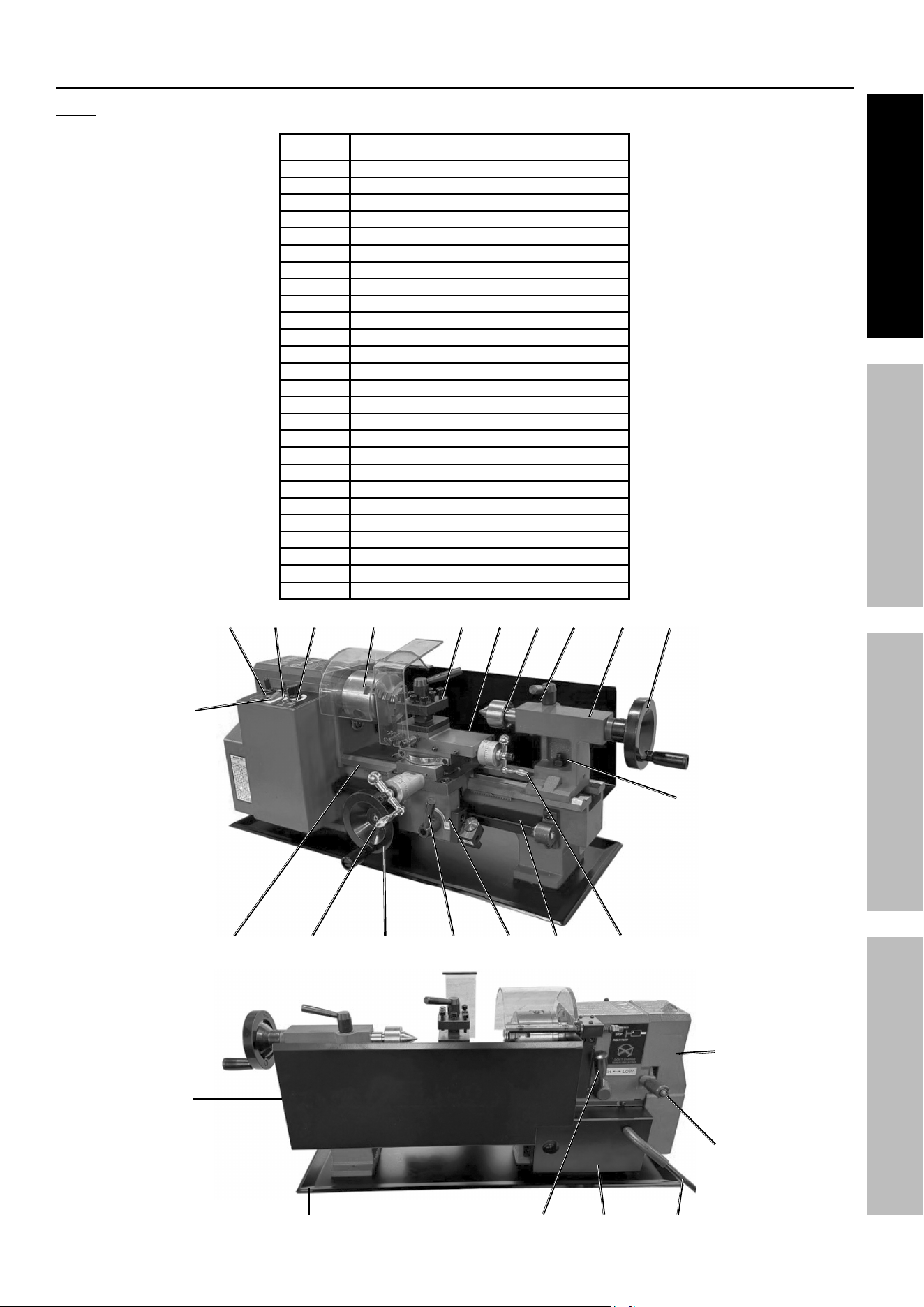
Mini Lathe Features
note: Refer to the parts list and assembly diagram at the end of manual.
part Description
1 Power Switch
2 Forward/OFF/Reverse Switch
3 Fuse
4 Speed Control Knob
5 Chuck
6 Tool Rest
7 Compound Rest
8 Live Center
9 Tailstock Quill Lock Handle
10 Tailstock
11 Tailstock Quill Adjust Handwheel
12 Tailstock Nut
13 Compound Rest Crank
14 Feeding Control Wheel
15 Cross Feeding Crank
16 Automatic Feeding Handle
17 Automatic Feeding Label
18 Bed Way
19 Lead Screw
20 Rear Splash Guard
21 Feeding Direction Selector
22 Power Cord
23 Chip Tray
24 Motor Cover
25 H/L Gearshift Lever
26 End Cover
2 3 4
5 6 7 8 9 10 11
1
12
18
15
14
16 17
19
13
20
23
25
24
22
21
26

Page 8 For technical questions, please call 1-888-866-5797. 93799
SaFety OperatiOn MaintenanceSetup
Setup - Before use:
read the entire iMpOrtant SaFety inFOrMatiOn section at the beginning of this
manual including all text under subheadings therein before set up or use of this product.
tO preVent SeriOuS inJury FrOM acciDentaL OperatiOn:
turn the power Switch of the tool off and unplug the tool from its electrical outlet
before performing any procedure in this section.
note: For additional information regarding the parts listed in the following pages,
refer to the Assembly Diagram near the end of this manual.
attaching rubber Feet
1. Unthread Bolts from bottom of Chip Tray.
2. Slide Rubber Feet onto Bolts and re-thread them
into bottom of Lathe through the Chip Tray holes.
3. Tighten securely.
Mounting to a Workbench
1. Unthread Bolts from bottom of unit.
2. Measure and drill holes in workbench.
3. Install using M6-1 bolts and washers
(sold separately) to secure Lathe
and Chip Tray to workbench.
installing Handwheel Handles
1. Use a flathead screwdriver and a 14mm open
ended wrench to thread handles onto wheels.
installing Guards
1. Attach Chuck Guard to the Hinge using two Screws.
2. To attach the Protective Cover, slide Screw
through protective cover, washer, spring and nut.
3. Thread screw into Compound Rest.
4. Slide notch in Protective Cover
over end of Slotted Screw.
adjusting the Mini Lathe
1. Clean off protective grease on Mini Lathe.
2. Make sure the three Chuck Mounting Bolts (4)
on the chuck are tight.
chuck Mounting Bolts
3. Turn the chuck by hand and
check that it rotates freely.
Page 9For technical questions, please call 1-888-866-5797. 93799
SaFetyOperatiOnMaintenance Setup
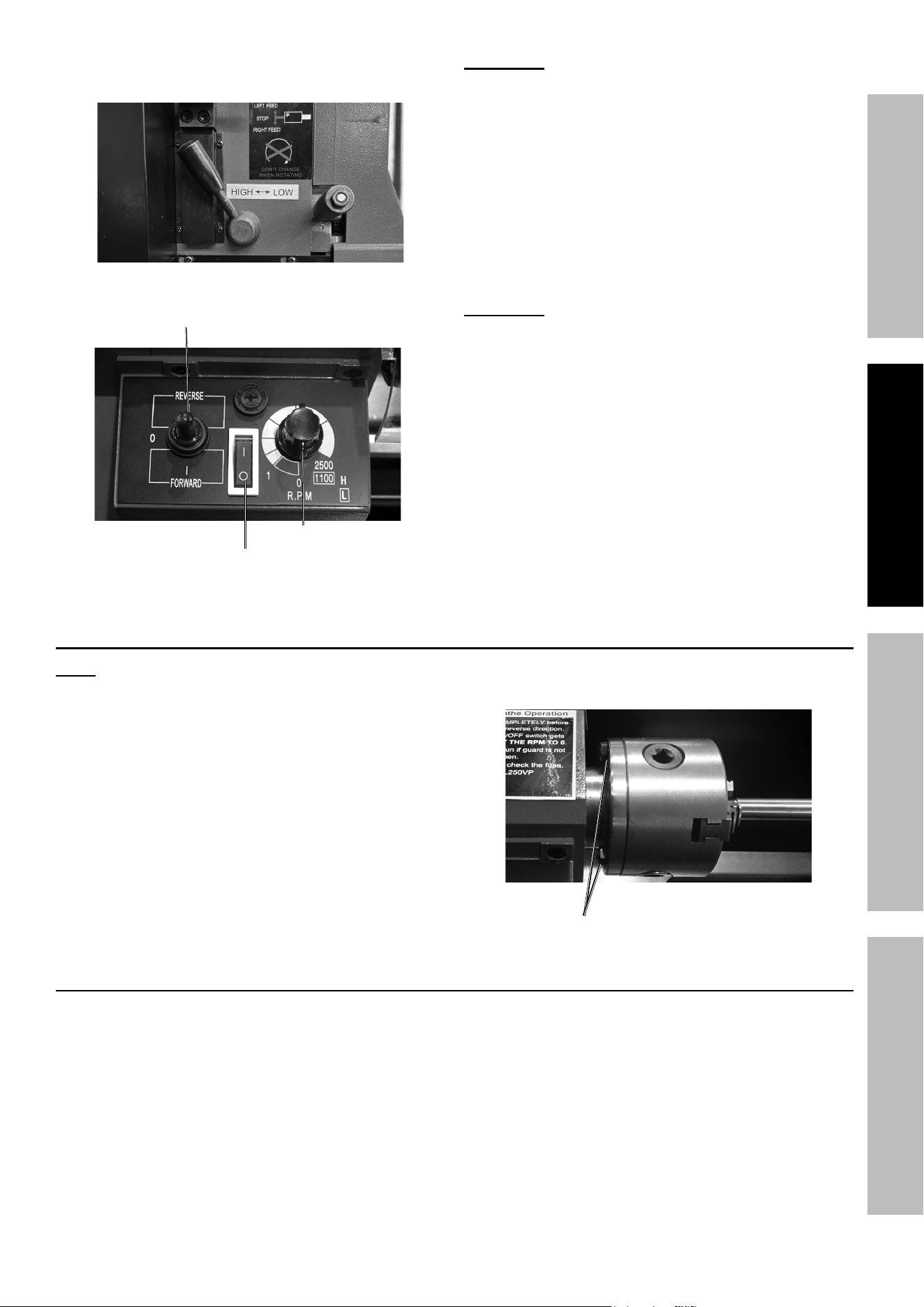
4. Move the Feeding Direction Selector (located
on the back of lathe) to the middle.
5. Make sure the Switch is in the OFF position.
On/Off Switch-
power Lamp
Speed control Knob
Forward/reverse Switch
WarninG: Adjust the speed control knob by turning
it to zero. Before turning on the mini lathe each time it
is to be used, this speed control knob must be at zero.
6. Plug in the electrical cord and turn the Switch to
the ON position and run the lathe for 3 minutes.
When the lathe is on, the Power Lamp will remain
on. Check that the lathe operates normally.
7. Check Compound Rest Crank and the Cross
Feeding Crank to see that they work properly. If
the cranks are too tight or too loose, turn the
adjusting screws located on both sides.
WarninG: The mini lathe must be completely
stopped before changing forward/reverse direction.
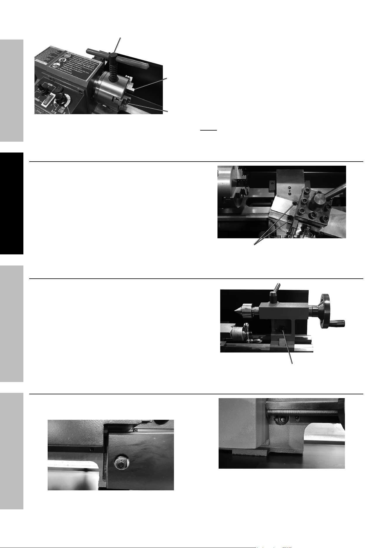
chuck replacement
note; Place a cloth or piece of wood on
the bedway at bottom of Chuck to avoid
damage caused by dropping chuck.
1. Loosen the M6 Nuts (6) on the three
Chuck Mounting Bolts (4) to replace chuck.
chuck Mounting Bolts
Jaw replacement
1. Unplug Lathe.
2. Place a towel under the Chuck to protect the
Bed Way from any Jaws that may drop.
3. Insert the Chuck Key (7) into the side of the
Chuck and turn clockwise while carefully slidiing
each Jaw out of it′s slot as it becomes free.
Page 10 For technical questions, please call 1-888-866-5797. 93799
SaFety OperatiOn MaintenanceSetup
chuck Key
Jaw
Jaw
4. Locate the groove marked #1 then rotate
the Chuck Key clockwise until the lead
thread of the scroll is in groove #1.
5. Slide Jaw #1 into the groove and slightly
rotate the Chuck Key counterclockwise, then
clockwise to engage the lead thread into Jaw.
6. Slide Jaw #2 into the groove and continue
turning the Chuck Key clockwise to
advance lead thread into next Jaw.
7. Repeat process for Jaw #3.
note: When mounting a workpiece, loosen all three
jaws at the same time to protect the inside threads.
compound rest adjustment
1. Turn Compound Rest Crank counterclockwise
to slide the top section of the Compound Rest
so the two screw holes (67) are exposed on
the lower section of the Compound Rest.
2. Adjust to required angle, then tighten screws.
Set Screw
tailstock rest adjustment
1. To change position or replace
tailstock, loosen nut (268).
nut
carbon Brush replacement
1. Remove brush covers on the Motor Controller
and the right bottom side of Speed Controller.
Motor cover
Speed controller Brush cover
Page 11For technical questions, please call 1-888-866-5797. 93799
SaFetyOperatiOnMaintenance Setup
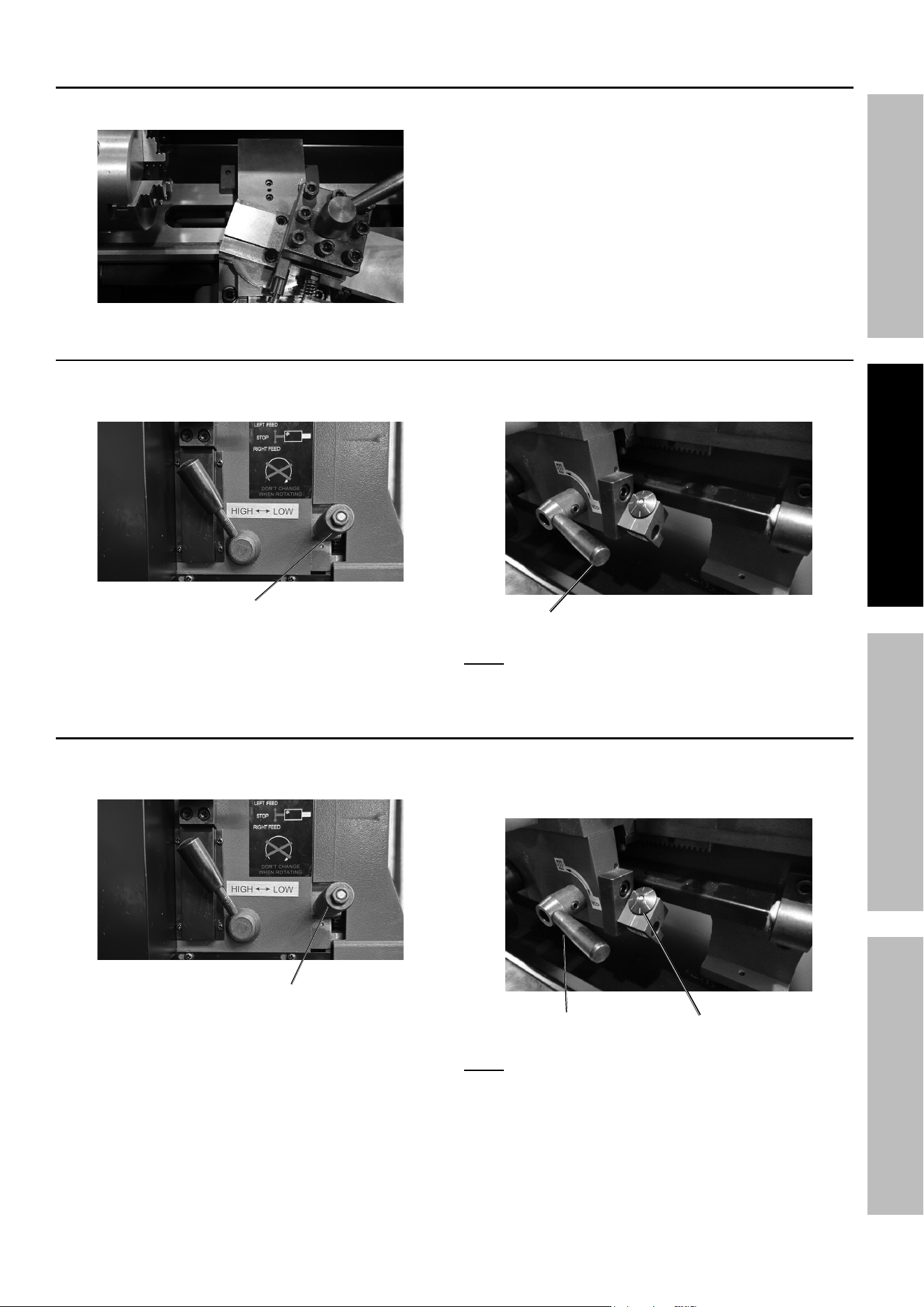
tool post adjustment
1. Loosen the lever to adjust the tool post position. 2. Re-tighten lever after adjusting.
3. To replace a cutter, loosen the socket head screws.
automatic Feeding
1. Adjust the feeding direction selector
to the desired direction.
Feeding Direction Selector
2. Press down the handle and continue
automatic feeding procedure.
Handle
note: When feeding, never try to
change the feeding direction.
threading
1. Set the feeding direction selector to
the desired thread direction.
Feeding Direction Selector
2. Press the handle down to match the calibrations
of the thread dial indicator and continue
the automatic threading procedure.
thread Dial indicator
Handle
note: When threading, never try to
change the threading direction.

Page 12 For technical questions, please call 1-888-866-5797. 93799
SaFety OperatiOn MaintenanceSetup
Operating instructions
read the entire iMpOrtant SaFety inFOrMatiOn section at the beginning of this
manual including all text under subheadings therein before set up or use of this product.
tool Set up
tO preVent SeriOuS inJury FrOM acciDentaL OperatiOn:
turn the power Switch of the tool off and unplug the tool from its electrical outlet
before performing any procedure in this section.
tO preVent SeriOuS inJury:
DO nOt Operate WitH any GuarD DiSaBLeD, DaMaGeD, Or reMOVeD.
Moving guards must move freely and close instantly.
Workpiece and Work area Set up
1. Designate a work area that is clean and well-lit.
The work area must not allow access by children
or pets to prevent distraction and injury.
2. Route the power cord along a safe route to reach
the work area without creating a tripping hazard or
exposing the power cord to possible damage. The
power cord must reach the work area with enough
extra length to allow free movement while working.
3. There must not be objects, such as utility lines,
nearby that will present a hazard while working.
General Operating instructions
note: Make sure that the Switch
is in the off-position, then plug in the tool.
1. Turn on the tool.
2. Use the Chuck to hold the workpiece firmly then
use the Rolling Center (143) to fix the other end.
note: Changing the rolling center to drilling
chuck starts the drilling immediately.
chuck
rolling center
note: Change the tool post angle and adjust
the compound rest for internal cutting.
3. Use the Chuck to firmly hold the workpiece and bring
cutter into position for face cutting or internal cutting.
note: The edge of the cutter must be at
the same height as the center.
chuck
4. Adjust the angle of the Compound Rest (105)
for bevel cutting.
compound rest
5. To prevent accidents, turn off the tool and unplug
the tool from its electrical outlet after use. Clean,
then store the tool indoors out of children’s reach.
Page 13For technical questions, please call 1-888-866-5797. 93799
SaFetyOperatiOnMaintenance Setup
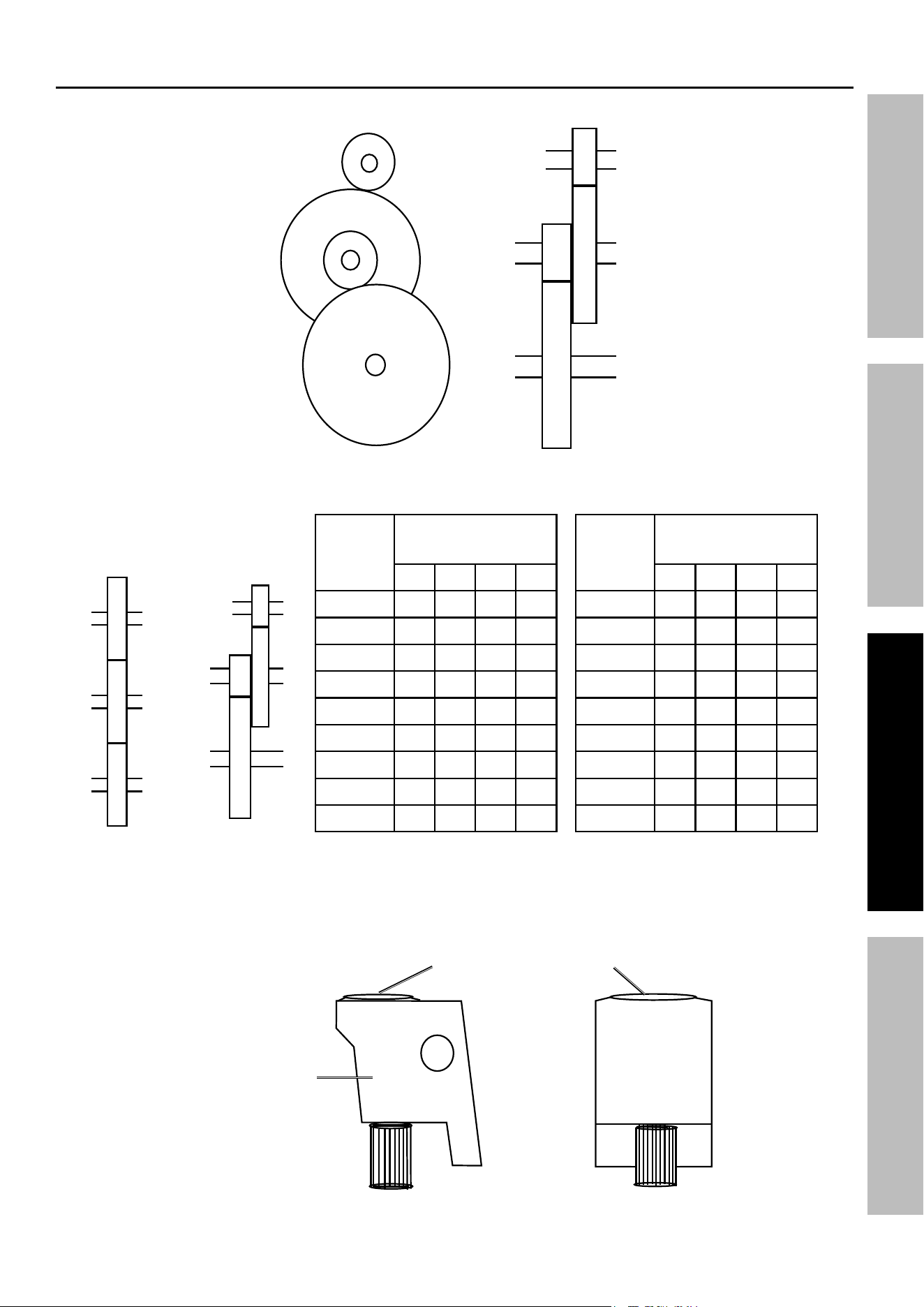
Setup instructions for threading Gears
By changing the gear setup it is possible to cut any thread size. The factory setup for Mini Lathe gears is as follows:
C
D
A
B
B
D
A
C
To change the thread size, use the gear box settings from the table below:
Thread
Per
Inch
Change Gear
Box
A B C D
12 40 65 / 30
13 40 65 60 30
14 40 65 / 35
16 40 65 / 40
18 40 65 / 45
19 40 50 60 57
20 40 65 / 50
22 40 65 / 55
24 40 65 / 60
Thread
Per
Inch
Change Gear
Box
A B C D
26 40 60 / 65
28 20 65 / 35
32 20 65 / 40
36 20 65 / 45
38 20 60 60 57
40 20 65 / 50
44 20 65 / 55
48 20 65 / 60
52 20 60 / 65
C
D
A
B
D
A
B
CHANGE GEAR BOX
When Lathe is ON and the Spindle is revolving, the threaded bar and the
Thread Dial Indicator will also be revolving as shown below.
Before operating, ensure that the alignment mark on the Housing is aligned with the Thread Dial Indicator.
thread Dial indicator
indicator Housing
Position A = 20T
Position B = 80T
Position C = 20T
Position D = 80T

Page 14 For technical questions, please call 1-888-866-5797. 93799
SaFety OperatiOn MaintenanceSetup
Maintenance and Servicing
procedures not specifically explained in this manual must
be performed only by a qualified technician.
tO preVent SeriOuS inJury FrOM acciDentaL OperatiOn:
turn the power Switch of the tool off and unplug the tool from its electrical outlet
before performing any procedure in this section.
tO preVent SeriOuS inJury FrOM tOOL FaiLure:
Do not use damaged equipment. if abnormal noise or vibration
occurs, have the problem corrected before further use.
cleaning, Maintenance, and Lubrication
1. BeFOre eacH uSe, inspect the general
condition of the tool. Check for:
• loose hardware,
• misalignment or binding of moving parts,
• cracked or broken parts,
• damaged electrical wiring, and
• any other condition that may
affect its safe operation.
2. aFter uSe, wipe external surfaces of the tool
with clean cloth. Use a brush to clear off filings
and debris; do NOT use compressed air.
3. Wipe a light coat of machine oil on
exposed metal parts to prevent rust.
4. WarninG! if the supply cord of this
power tool is damaged, it must be replaced
only by a qualified service technician.

Page 15For technical questions, please call 1-888-866-5797. 93799
SaFetyOperatiOnMaintenance Setup
troubleshooting
problem possible causes Likely Solutions
Motor and electrical
Lathe will not
start or a breaker
trips on startup.
1. Cord not connected.
2. No power at outlet.
3. Fuse has blown.
4. Chuck Guard safety
interlock not in place.
5. PC Board (182) faulty.
6. Power Switch (178), Forward/OFF/
Reverse Switch (181) and/or Speed
Control Knob (180) not working.
7. Internal damage or wear
(such as wiring or motor.)
1. Check that cord is plugged in.
2. Check power at outlet. If outlet is unpowered,
turn off tool and check circuit breaker. If breaker
is tripped, make sure circuit is right capacity
for tool and circuit has no other loads.
3. Check for short, replace fuse
4. Rotate Pin (251) so it seats in Rotate Plate (252).
5. Inspect PC Board, have replaced if needed.
6. Check and replace as needed.
7. Have technician service tool.
Lathe stalls. 1. Incorrect workpiece material (metal).
2. Drive Pulleys slipping on shaft.
3. Removing too much
material per pass.
1. Use metal suited for Lathe.
2. Tighten or replace Pulleys (27,148).
3. Remove less material per pass.
Lathe operates
slowly.
Extension cord too long or
wire size too small.
Eliminate use of extension cord. If an extension
cord is needed, use shorter/heavier gauge cord.
Performance
decreases
over time
1. Accessory dull or damaged.
2. Carbon Brushes worn or damaged.
1. Keep cutting accessories sharp.
Replace as needed.
2. Replace Carbon Brushes.
Excessive noise
or rattling.
1. Pulley setscrews missing or loose.
2. Motor fan hitting cover.
3. Belt (if equipped) too loose (slipping)
or too tight (bearing damage).
4. Internal motor damage or wear.
1. Check Pulley keys and setscrews.
Replace or tighten as needed.
2. Tighten fan cover or replace as needed.
3. Properly tension belt.
4. Have technician service tool.
Overheating. 1. Motor overloaded.
2. Forcing machine to work too fast.
3. Accessory dull or damaged.
4. Incorrect RPM or feed rate.
5. Gear setup is too tight, gears bind.
6. Blocked motor housing vents.
7. Motor being strained by long or
small diameter extension cord.
1. Reduce load on motor. Loosen drive Belt
2. Allow machine to work at its own rate.
3. Keep cutting accessories sharp.
Replace as needed.
4. Check that RPM feed rate chart for
appropriate rates for operation.
5. Adjust gears so there is a small amount of
play and the gears move freely and smoothly
when the Chuck is rotated by hand.
6. Wear ANSI-approved safety goggles and NIOSH-
approved dust mask/respirator while blowing
dust out of motor using compressed air.
7. Eliminate use of extension cord. If an
extension cord is needed, use one with the
proper diameter for its length and load.
tool performance
Follow all safety precautions whenever diagnosing or servicing the tool.
Disconnect power supply before service.

Page 16 For technical questions, please call 1-888-866-5797. 93799
SaFety OperatiOn MaintenanceSetup
problem possible causes Likely Solutions
Whole unit
vibrates
excessively
while in use.
1. Workpiece unbalanced.
2. Loose or damaged belt(s).
3. Drive Pulleys not aligned.
4. Worn or broken gear.
5. Chuck loose or unbalanced.
6. Spindle bearings worn.
1. Re-center workpiece.
2. Tighten or replace the belt.
3. Align Drive Pulleys (27, 148).
4. Inspect gears and replace if needed.
5. Tighten Nuts (6) or have a qualified
technician rebalance Chuck.
6. Have a qualified technician replace bearings.
Uneven surface
finish.
1. Incorrect RPM or feed rate for job.
2. Dull or incorrect tool for job.
3. Gibs need adjustment.
4. Tool positioned too high.
1. Adjust RPM and/or feed rate.
2. Sharpen and/or change tool.
3. Tighten Gibs (94 and/or 107).
4. Lower position of tool.
Unable to
remove tapered
tool from
Tailstock.
Quill not fully seated in Tailstock
or taper was inserted without
first removing debris.
Turn quill handwheel until taper is forced out
of quill. In the future make sure that the quill
is fully seated in the tailstock and that the tool
is wiped free of debris before installing.
Cross Slide,
Compound Slide
and/or carriage
feed do not
move smoothly.
1. Gibs need adjusting.
2. Handwheel or crank
handles are too loose.
3. Leadscrew worn or
needs adjustment,
1. Loosen or tighten the Gib Screws (99 and/or 106).
2. Tighten Handwheel and/or crank handle.
3. Tighten Leadscrew fasteners or have lead
screw replaced by a qualified technician.
Difficulty moving
Cranks of
Cross Slide,
Compound Slide
and/or Carriage
Handwheel.
1. Debris jammed around Gibs.
2. Gibs adjusted too tight.
3. Bedways need lubrication.
1. Remove Gibs, clean Gibs and all adjacent
areas. Re-lubricate, then reinstall Gibs.
2. Loosen Gib Screws (99 and/or 106)
and lubricate bedways.
3. Lubricate bedways.
Cutting Tool
or machine
components
vibrate
excessively
during operatio
1. Tool Rest (112) too loose.
2. Cutting tool jutting too far out of Tool
Post or not secure.
3. Gibs need adjustment.
4. Cutting tool need sharpening.
5. RPM or feed rate incorrect for job.
1. Clean any debris around Tool Post,
then securely tighten Tool Post.
2. Remove and reinstall cutting tool so that at least
two screws hold it securely in place and no more
than 1/3 of the tool extends beyond the Tool Post.
3. Adjust Gib Screws (99 and/or 106).
4. Sharpen or replace tool.
5. Check and adjust for recommended
RPM and/or feed rate.
Finished piece
uneven from one
end to the other.
Chuck and Tailstock are not aligned. Realign Tailstock.
Difficulty moving
Chuck Jaws.
Debris lodged between
Jaws and Chuck.
Remove Jaws. Clean and lubricate
Chuck threads, then reinstall Jaws.
Carriage will
not feed.
1. Gear or gears not engaged.
2. Damaged gears.
3. Feed Handle screw loose.
1. Check gears and adjust positions.
2. Check and replace damaged gears.
3. Tighten feed handle screw.
Follow all safety precautions whenever diagnosing or servicing the tool.
Disconnect power supply before service.
trouble Shooting (continued)

Page 17For technical questions, please call 1-888-866-5797. 93799
SaFetyOperatiOnMaintenance Setup
parts List and Diagram
pLeaSe reaD tHe FOLLOWinG careFuLLy
THE MANUFACTURER AND/OR DISTRIBUTOR HAS PROVIDED THE PARTS LIST AND ASSEMBLY DIAGRAM
IN THIS MANUAL AS A REFERENCE TOOL ONLY. NEITHER THE MANUFACTURER OR DISTRIBUTOR
MAKES ANY REPRESENTATION OR WARRANTY OF ANY KIND TO THE BUYER THAT HE OR SHE IS
QUALIFIED TO MAKE ANY REPAIRS TO THE PRODUCT, OR THAT HE OR SHE IS QUALIFIED TO REPLACE
ANY PARTS OF THE PRODUCT. IN FACT, THE MANUFACTURER AND/OR DISTRIBUTOR EXPRESSLY
STATES THAT ALL REPAIRS AND PARTS REPLACEMENTS SHOULD BE UNDERTAKEN BY CERTIFIED AND
LICENSED TECHNICIANS, AND NOT BY THE BUYER. THE BUYER ASSUMES ALL RISK AND LIABILITY
ARISING OUT OF HIS OR HER REPAIRS TO THE ORIGINAL PRODUCT OR REPLACEMENT PARTS
THERETO, OR ARISING OUT OF HIS OR HER INSTALLATION OF REPLACEMENT PARTS THERETO.
record product’s Serial number Here:
note: If product has no serial number, record month and year of purchase instead.
note: Some parts are listed and shown for illustration purposes only, and are not available
individually as replacement parts. Specify UPC 792363937993 when ordering parts.

Page 18 For technical questions, please call 1-888-866-5797. 93799
SaFety OperatiOn MaintenanceSetup
part Description Qty
1 Bed Way 1
2 3 Jaw Chuck 1
3 Spindle 1
4 Chuck Mounting Bolt M6x25 3
6 Nut M6 5
7 Key 5x40 1
8 Key 4x8 2
9 Screw M5x12 6
10 Cover 2
11 Ball Bearing 80206 2
12 Spacer 1
13 Headstock Casting 1
14 H/L Gear 21T/29T 1
15 Spacer 1
16 Spur Gear 45T 1
17 Nut M27x1.5 1
18 Set Screw M5x8 1
19 Steel Ball 5 2
20 Compression Spring 3
21 Set Screw M6x8 3
22 Retaining Ring 12 2
23 Ball Bearing 80101 2
24 H/L Gear 12T/20T 1
25 Parallel Key 4x45 1
26 H/L Gear Shaft 1
27 Pulley 1
28 Retaining Ring 10 2
29 Timing Belt Lx136 1
30 Shifting Fork 1
31 Shifting Arm 1
32 Shifting Knob 1
33 Shifting Lever 1
part Description Qty
34 Shifting Grip 1
35 Handle 1
36 Handle Mount 1
37 Spring 1
38 Indicator 1
39 Pinion 25T 1
40 Support Screw 2
41 Pinion 20T 1
42 Fixed Cover 1
43 Screw M6x20 2
45 Gear 45T 1
46 Shaft 1
47 Parallel Key 3x8 1
48 Mount 1
49 Screw M5x18 2
50 Gearwheel 20T 2
51 Washer M6 4
52 Screw M6x8 3
53 Cover 1
54 Screw M5x45 2
55 Thread Cutting Chart 1
56 Screw M5x8 8
57 Washer M4 2
58 Bush w/Key 1
59 Gearwheel 80T 2
60 Shaft 1
61 Support Plate 1
62 Washer 8 3
63 Nut M8 3
64 Shaft 1
65 Dial Label 16T 1
66 Shaft 1
parts List

Page 19For technical questions, please call 1-888-866-5797. 93799
SaFetyOperatiOnMaintenance Setup
part Description Qty
67 Screw M6x16 9
68 Dial Indicator Body 1
69 Set Screw M4x10 3
70 Apron 1
71 Gib Strip 1
72 Washer 2
73 Screw M4x8 4
74 Shaft 1
75 Half Nut Base 2
76 Angle Block 1
77 Screw M4x10 2
78 Groove Cam 1
79 Handle 1
80 Shaft 1
81 Feeding Gear 11T/54T 1
82 Feeding Gear 24T 1
83 Screw M6x10 4
84 Wheel 2
85 Knob 2
86A Handle Large 1
86B Handle Small 1
87 Dial 2
88 Bracket 1
89 Feeding Screw 1
90 Nut M5 4
91 Screw M6x12 6
92 Slide Plate 2
93 Saddle 1
94 Gib Strip 1
95 Feeding Nut Imperial 1
96 Swivel Disk 1
part Description Qty
97 Screw M8x20 6
98 Nut M4 6
99 Screw M4x16 3
100 Cross Slide 1
101 Screw M5x10 2
105 Compound Rest(B) 1
106 Screw M4x14 3
107 Gib Strip 1
108 Compound Rest(A) 1
109 Position Pin 1
110 Screw M6x25 8
111 Clamping Lever 1
112 Tool Rest 1
113 Stud M10x65 1
114 Cross Feed Screw 1
115 Bracket 1
116 Screw M4x12 2
119 Washer 1
120 Model Label 1
121 Dial Indicator Label 1
122 Switch Label 1
123 Control Box 1
124 Plug w/Cord 1
125 Rubber Foot 4
126 Chip Tray 1
127 Bracket 1
128 Key M3x16 1
129 Lead Screw 1
131 Bracket 1
133 Screw M3x10 3
134 Rack 1
parts List (continued)

Page 20 For technical questions, please call 1-888-866-5797. 93799
SaFety OperatiOn MaintenanceSetup
part Description Qty
135 Clamp Plate 1
136 Washer M10 1
137 Screw M5x16 1
138 Tailstock Casting 1
139 Tailstock Screw 1
140 Bracket 1
141 Screw M4x10 2
142 Tailstock Quill 1
143 Rolling Center 1
144 Stud M8x40 1
145 Clamp 1
146 Handle 1
148 Pulley 1
150 Motor 1
151 Motor Cover 1
152 Cable Gland 1
153 Rear Splash Guard 1
154 F/N/R Label 1
155 High-Low Label 1
156 Top Warning Label 1
157 Gearwheel 30T 1
158 Gearwheel 35T 1
159 Gearwheel 40T 2
160 Gearwheel 45T 1
161 Gearwheel 50T 1
part Description Qty
162 Gearwheel 55T 1
163 Gearwheel 57T 1
164 Gearwheel 60T 1
165 Gearwheel 65T 1
166 External Jaws (set) (not shown) 1
167 3-Jaw Chuck Key (not shown) 1
170 Screw M4x8 1
171 Clamp Block 1
172 Check Ring 8 1
173 Screw M5x10 4
174 Protector 1
175 Screw M5x10 2
176 Nut M6 4
177 Screw M6x25 2
178 Power Switch 1
179 Fuse Box 1
180 Variable Speed Control Knob 1
180A Potentiometer 1
181 Forward/Off/Reverse Switch 1
182 P.C.Board 1
184 Screw M5x10 1
185 Spring Washer 5 1
186 Washer 5 2
187 Key 3x16 1
188 Spacer 1
parts List (continued)

Page 21For technical questions, please call 1-888-866-5797. 93799
SaFetyOperatiOnMaintenance Setup
part Description Qty
190 Spring 2
191 Washer 8 1
192 Spring Washer 6 2
193 Screw M8 x 55 2
194 Screw M4 x 38 1
195 Nut M4 1
196 Tailstock Plate 1
197 Screw M5 x 16 1
198 Flange 1
199 Screw M5x25 1
200 Key 3x12 1
201 Chuck Protect Cover 1
202 Hinge 1
205 Spring Washer M6 1
206 Large Washer M6 1
207 Spring 1
208 Washer 6 2
209 Screw M3x4 4
210 Switch Cover 1
211 Screw M5x16 2
212 Fixed Cover 1
235 Protective Cover 1
236 Slotting Screw 1
237 Compression Spring 1
238 Slotting Screw M6x30 1
part Description Qty
239 Small Washer 6 1
240 Nut M6 1
251 Round Pin 1
252 Rotate Plate 1
253 Screw ST2.9x4.5 2
254 Cover 1
255 Micro Switch 1
256 Dustproof Sleeve 1
257 Protective Cover for Leadscrew 1
258 Screw M5x8 3
265 Spring Washer 6 2
266 Large Washer 6 2
267 Screw M6x25 2
268 Nut M10 1
269 Screw M5x14 2
270 Leadscrew Support 1
271 Nut M4 2
272 Protective Cover 1
273 Screw M4x6 2
300 Screw 1
301 Label 1
302 Label 1
303 Plate 1
304 Screw M6x12 1
309 Washer 10 1
parts List (continued)
Page 22 For technical questions, please call 1-888-866-5797. 93799
SaFety OperatiOn MaintenanceSetup
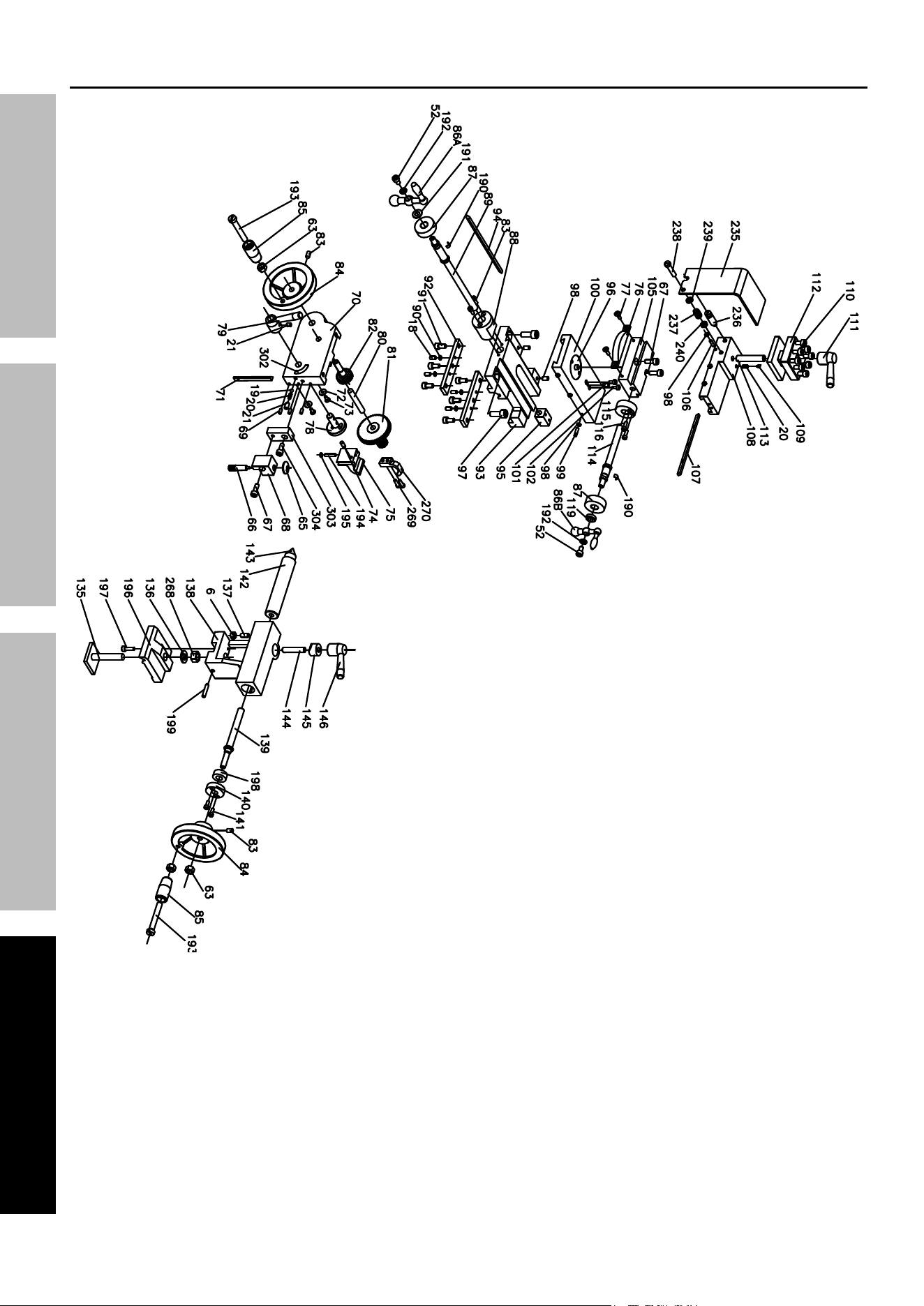
assembly Diagram
Page 23For technical questions, please call 1-888-866-5797. 93799
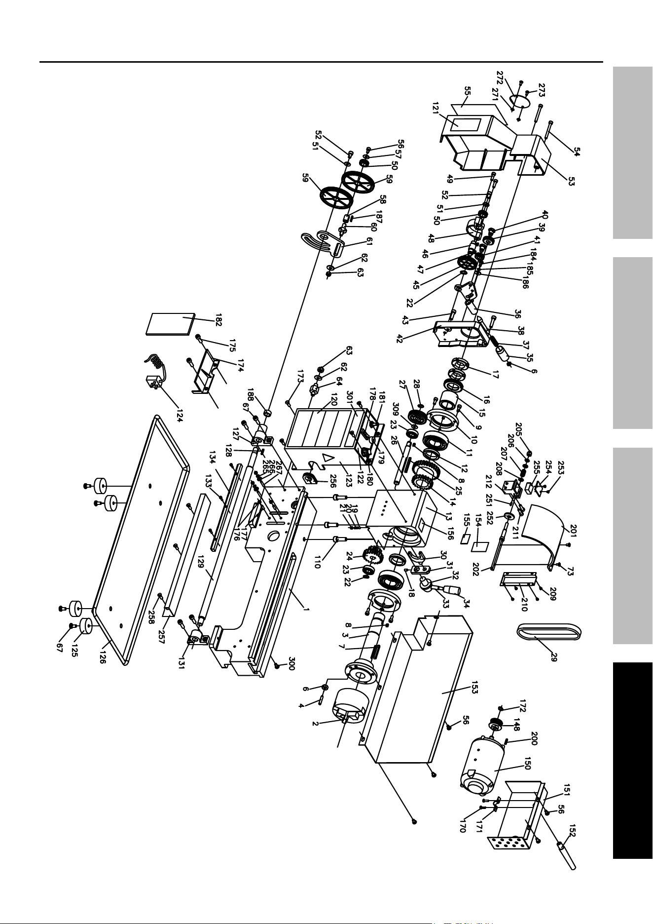
SaFetyOperatiOnMaintenance Setup
assembly Diagram

Limited 90 Day Warranty
Harbor Freight Tools Co. makes every effort to assure that its products meet high quality and durability standards,
and warrants to the original purchaser that this product is free from defects in materials and workmanship for the
period of 90 days from the date of purchase. This warranty does not apply to damage due directly or indirectly,
to misuse, abuse, negligence or accidents, repairs or alterations outside our facilities, criminal activity, improper
installation, normal wear and tear, or to lack of maintenance. We shall in no event be liable for death, injuries
to persons or property, or for incidental, contingent, special or consequential damages arising from the use of
our product. Some states do not allow the exclusion or limitation of incidental or consequential damages, so the
above limitation of exclusion may not apply to you. THIS WARRANTY IS EXPRESSLY IN LIEU OF ALL OTHER
WARRANTIES, EXPRESS OR IMPLIED, INCLUDING THE WARRANTIES OF MERCHANTABILITY AND FITNESS.
To take advantage of this warranty, the product or part must be returned to us with transportation charges
prepaid. Proof of purchase date and an explanation of the complaint must accompany the merchandise.
If our inspection verifies the defect, we will either repair or replace the product at our election or we may
elect to refund the purchase price if we cannot readily and quickly provide you with a replacement. We will
return repaired products at our expense, but if we determine there is no defect, or that the defect resulted
from causes not within the scope of our warranty, then you must bear the cost of returning the product.
This warranty gives you specific legal rights and you may also have other rights which vary from state to state.
26677 agoura road • calabasas, ca 91302 • 1-888-866-5797