USER MANUAL
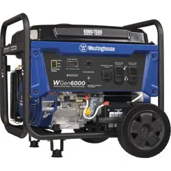
WGen6000
Portable Generator
6000 Running Watts | 7500 Peak Watts
2 | Westinghouse Portable Power
DISCLAIMERS:
All information, illustrations and specications in this manual are based on the latest information available at the time of
publishing. The illustrations used in this manual are intended as representative reference views only. Moreover, because
of our continuous product improvement policy, we may modify information, illustrations and/or specications to explain
and/or exemplify a product, service or maintenance improvement. We reserve the right to make any change at any time
without notice. Some images may vary depending upon which model is shown.
ALL RIGHTS RESERVED:
No part of this publication may be reproduced or used in any form by any means – graphic, electronic or mechanical,
including photocopying, recording, taping or information storage and retrieval systems – without the written permission
of MWE Investments LLC.
DANGER
This manual contains important instructions for operating this generator. For your safety and the
safety of others, be sure to read this manual thoroughly before operating the generator. Failure to
properly follow all instructions and precautions can cause you and others to be seriously hurt or
killed.
Model
Number
Running
Watts
Peak
Watts
Fuel
Tank
Size
(L/G)
Rated
Speed
(RPM)
Ignition
Type
Spark
plug
Engine
Disp (cc)
Stroke X
Bore
Oil
Capacity
(L) Oil Type
WGen6000 6000 7500 25/6.6 3600 TCI F7TC 420 66X90 1.10 10W30
NOTICE
Even with a carburetor modication, engine horsepower will decrease about 3.5% for each 300 meter (1,000 foot) increase in altitude. The
eect of altitude on horsepower will be greater if no carburetor modication is made. A decrease in engine horsepower will decrease the
power output of the generator. Contact our service team to order altitude kits.
FOR YOUR RECORDS:
Date of Purchase:
Generator Model Number:
Purchased from Store/Dealer:
Generator Serial Number:
TECHNICAL SPECIFICATIONS
HAVE QUESTIONS? Email us at service@wpowereq.com
or call 1-855-944-3571
Operating, servicing and maintaining this equipment can expose you to chemicals including engine exhaust,
carbon monoxide, phthalates, and lead, which are known to the State of California to cause cancer and birth
defects or other reproductive harm. To minimize exposure, avoid breathing exhaust, do not idle the engine
except as necessary, service your equipment in a well-ventilated area and wear gloves or wash your hands
frequently when servicing your equipment. For more information go to www.P65Warnings.ca.gov.
WARNING
Westinghouse Portable Power | 3
IMPORTANT: KEEP YOUR PURCHASE RECEIPT TO ENSURE TROUBLE-FREE WARRANTY
COVERAGE.
PRODUCT REGISTRATION
To ensure trouble-free warranty coverage, it is important you register your Westinghouse generator.
You can register your generator by either:
1. Filling in the product registration form below and mailing to:
Product Registration
MWE Investments LLC
777 Manor Park Drive
Columbus, Ohio 43228
2. Registering your product Online at wpowereq.com/register
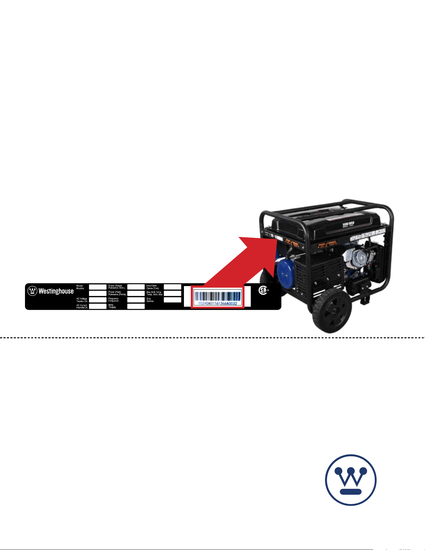
To register your generator you will need to locate the following information:
WESTINGHOUSE PRODUCT REGISTRATION FORM
PERSONAL INFORMATION GENERATOR INFORMATION
First Name: _______________________________________ Model Number: _____________________________________
Last Name: _______________________________________ Serial Number: ______________________________________
Street Address: ___________________________________ Date Purchased: ____________________________________
Street Address: ___________________________________ Purchased From: ____________________________________
City, State, ZIP: ____________________________________
Country: __________________________________________
Phone Number: ___________________________________
E-Mail: ___________________________________________
Made in China/ Fabriqu é en Chine
CSA Master Contract
Number :
Numéro de contrat
principa l de CS A
MWE Investments LLC
Columbus Ohio 43228 USA
Con u à columbus , Oh io,tats-Unis
MWE Investments LLC
Columbus Ohio 43228 Etats-Unis
Par t N0.
Numéro de
pièc e
Designed in Columbus , Ohio USA
WHERE IS MY SERIAL NUMBER?

4 | Westinghouse Portable Power
TABLE OF CONTENTS
TECHNICAL SPECIFICATIONS ..................2
PRODUCT REGISTRATION .....................3
For Your Records: ..........................3
Product Registration .......................3
Product Registration Form ...................3
SAFETY .....................................5
Safety Denitions ..........................5
Safety Symbol Denitions ...................5
General Safety Rules ........................6
Safety Labels and Decals ....................7
UNPACKING .................................9
What Comes in the Box ......................9
Wheel Kit Accessories Box ...................9
ASSEMBLY .................................10
Installing Wheels and Feet ....................10
Installing the Battery ........................11
FEATURES .................................12
Generator Features .........................12
Control Panel Features .....................14
OPERATION .................................15
Before Starting the Generator .................15
Altitude Kit Part Number .....................15
Power Cord ..............................16
Using Extension Cords ...................16
Using Westinghouse Power Cord ...........16
Transfer Switch Connections ..................17
How to Float the Neutral ...................17
Engine Fluids and Fuel .......................17
Adding Gasoline to the Fuel Tank ...........18
Power Output and Demand ...................19
Starting the Generator ......................20
Stopping the Generator ......................21
Normal Operation .......................21
During an Emergency ....................21
MAINTENANCE ..............................21
Maintenance Schedule ......................22
Cleaning the Spark Arrestor ...................23
Draining Carburetor .........................23
Engine Oil Maintenance .....................24
Engine Oil Specication ...................24
Checking Engine Oil .....................24
Adding Engine Oil .......................24
Changing Engine Oil .....................25
Air Filter Maintenance .......................25
Cleaning the Air Filter ....................25
Spark Plug Maintenance .....................26
Checking and Adjusting Valve Lash. . . . . . . . . . . . . 27
Testing GFCI Outlets ........................27
Battery Service. . . . . . . . . . . . . . . . . . . . . . . . . . . . . 27
Replacing Battery ........................28
Cleaning the Generator ......................28
STORAGE ...................................28
TROUBLE SHOOTING .........................29
EXPLODED AND ENGINE VIEWS ................30
WGen6000 Exploded View ...................30
WGen6000 Engine View .....................32
SCHEMATICS ................................34
WGen6000 Schematic .......................34
SPECIFICATIONS .............................35
Westinghouse Portable Power | 5
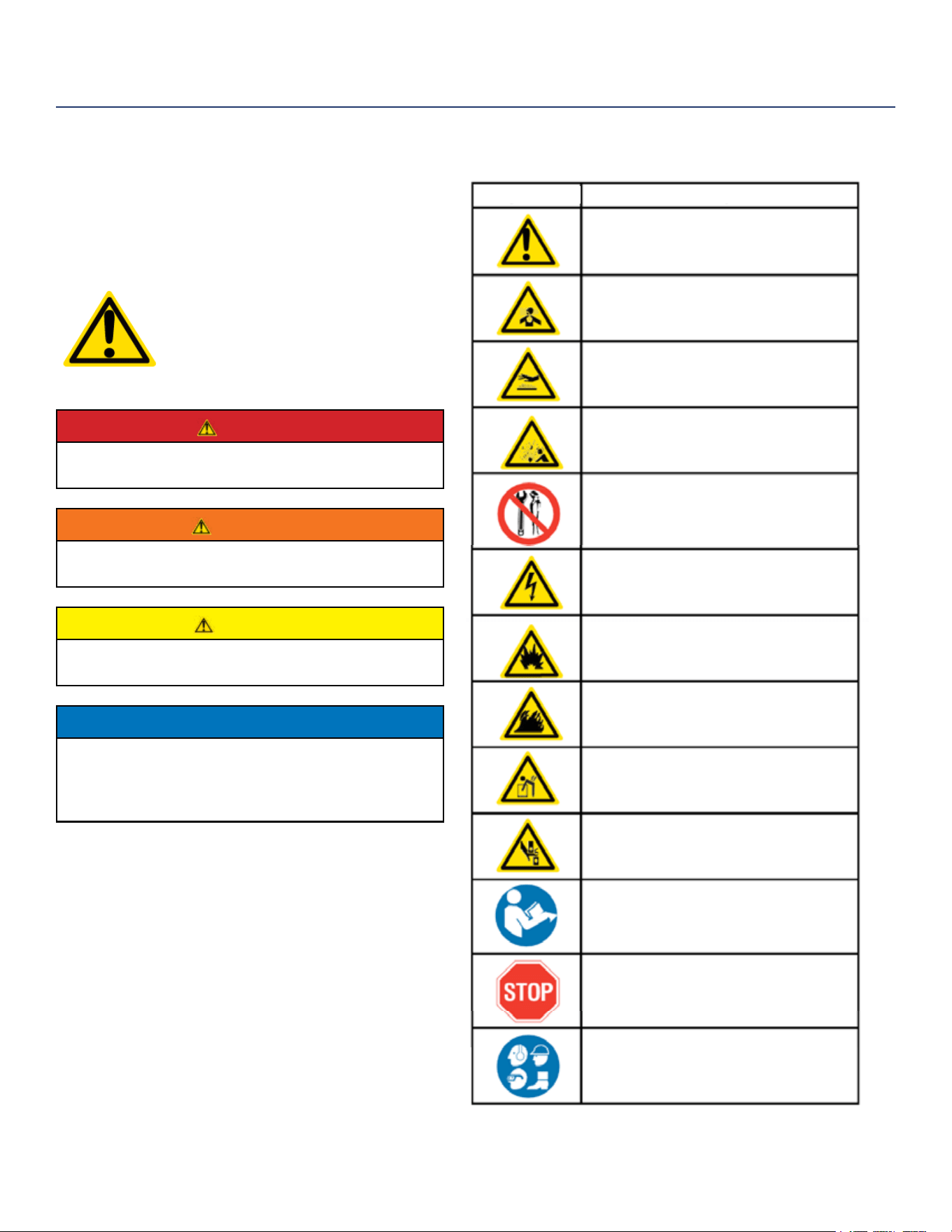
SAFETY DEFINITIONS
The words DANGER, WARNING, CAUTION and
NOTICE are used throughout this manual to highlight
important information. Be certain that the meanings of
these alerts are known to all who work on or near the
equipment.
This safety alert symbol appears
with most safety statements. It
means attention, become alert, your
safety is involved! Please read and
abide by the message that follows
the safety alerts symbol.
DANGER
Indicates a hazardous situation which, if not
avoided, will result in death or serious injury.
WARNING
Indicates a hazardous situation which, if not
avoided, could result in death or serious injury.
CAUTION
Indicates a hazardous situation which, if not
avoided, could result in minor or moderate injury.
NOTICE
Indicates a situation which can cause damage
to the generator, personal property and/or the
environment, or cause the equipment to operate
improperly.
NOTE: Indicates a procedure, practice or condition
that should be followed in order for the
generator to function in the manner
intended.
SAFETY
SAFETY SYMBOL DEFINITIONS
Explosion Hazard
Fire Hazard
Electrical Shock Hazard
Lifting Hazard
Pinch-Point Hazard
Read Manufacturer’s Instructions
Read Safety Messages
Before Proceeding
Wear Personal Protective
Equipment (PPE)
Safety Alert Symbol
Asphyxiation Hazard
Burn Hazard
Burst/Pressure Hazard
Don’t leave tools in the area
Symbol Description
6 | Westinghouse Portable Power
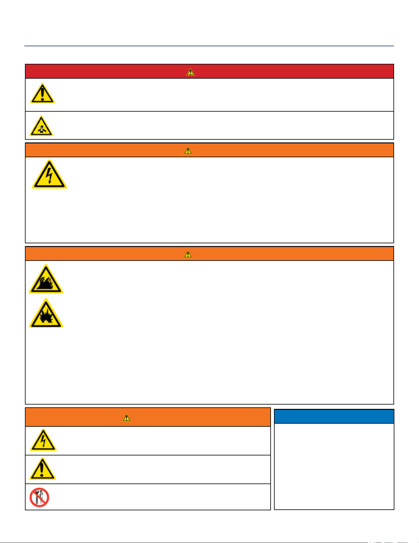
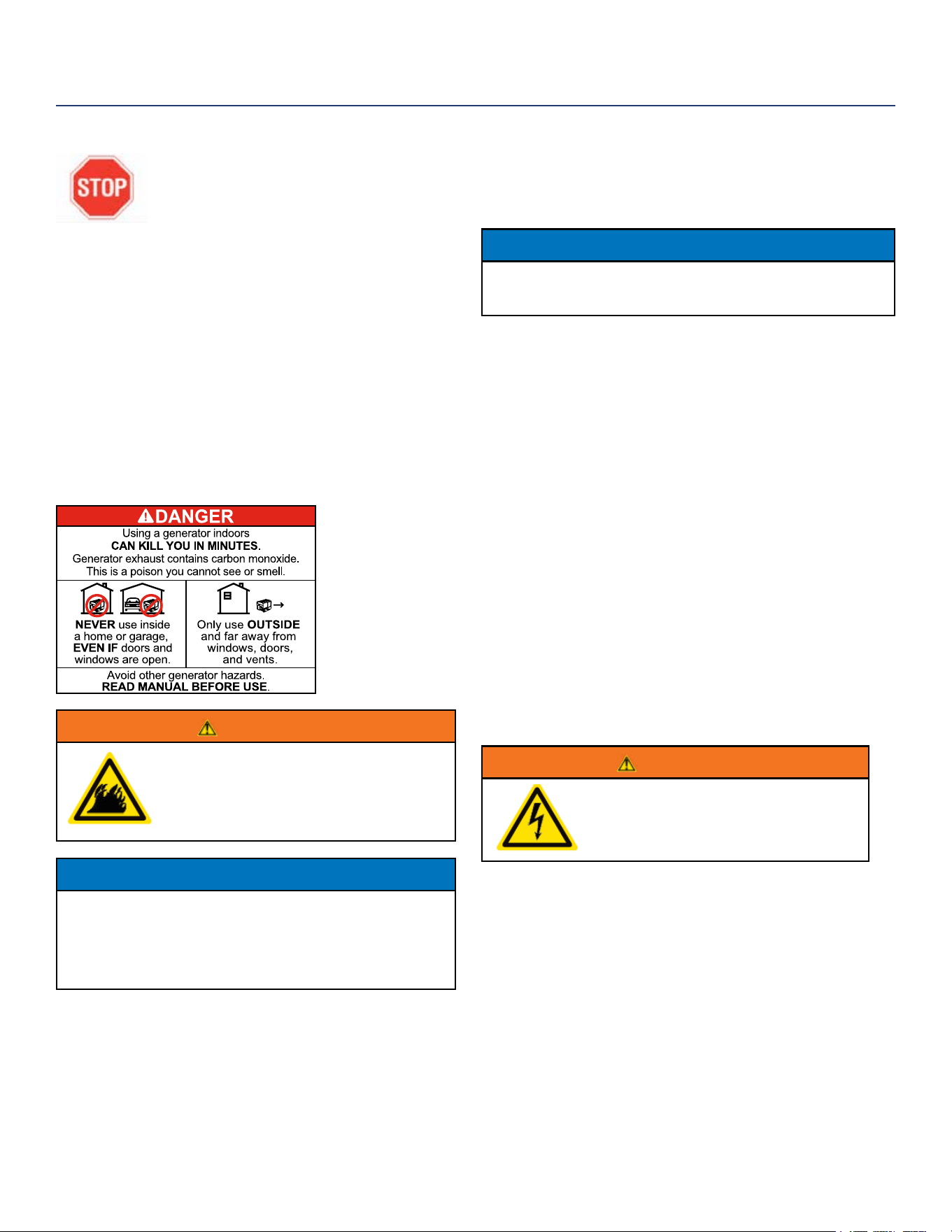
DANGER
Never use the generator in a location that is wet or damp. Never expose the generator to rain, snow, water
spray or standing water while in use. Protect the generator from all hazardous weather conditions. Moisture
or ice can cause a short circuit or other malfunction in the electrical circuit.
Never operate the generator in an enclosed area. Engine exhaust contains carbon monoxide. Only operate
the generator outside and away from windows, doors and vents.
WARNING
Voltage produced by the generator could result in death or serious injury.
• Never operate the generator in rain or a ood plain unless proper precautions are taken to avoid
being subject to rain or a ood.
• Never use worn or damaged extension cords.
• Always have a licensed electrician connect the generator to the utility circuit.
• Never touch an operating generator if the generator is wet or if you have wet hands.
• Never operate the generator in highly conductive areas such as around metal decking or steel works.
• Always use grounded extension cords. Always use three-wire or double-insulated power tools.
• Never touch live terminals or bare wires while the generator is operating.
• Be sure the generator is properly grounded before operating.
WARNING
Gasoline and gasoline vapors are extremely ammable and explosive under certain conditions.
• Always refuel the generator outdoors, in a well-ventilated area.
• Never remove the fuel cap with the engine running.
• Never refuel the generator while the engine is running. Always turn engine o and allow the generator
to cool before refueling.
• Only ll fuel tank with gasoline.
• Keep sparks, open ames or other form of ignition (such as match, cigarette, static electric source)
away when refueling.
• Never overll the fuel tank. Leave room for fuel to expand. Overlling the fuel tank can result in a
sudden overow of gasoline and result in spilled gasoline coming in contact with HOT surfaces.
Spilled fuel can ignite. If fuel is spilled on the generator, wipe up any spills immediately. Dispose of
rag properly. Allow area of spilled fuel to dry before operating the generator.
• Wear eye protection while refueling.
• Never use gasoline as a cleaning agent.
• Store any containers containing gasoline in a well-ventilated area, away from any combustibles or
source of ignition.
• Check for fuel leaks after refueling. Never operate the engine if a fuel leak is discovered.
WARNING
Never operate the generator if powered items overheat, electrical
output drops, there is sparking, ames or smoke coming from the
generator, or if the receptacles are damaged.
Never use the generator to power medical support equipment.
Always remove any tools or other service equipment used during
maintenance from the generator before operating.
NOTICE
Never modify the generator.
Never operate the generator if it
vibrates at high levels, if engine
speed changes greatly or if the
engine misres often.
Always disconnect tools or
appliances from the
generator before starting.
GENERAL SAFETY RULES
SAFETY
Westinghouse Portable Power | 7
Made in China/ Fabriqu é en Chine
CSA Master Contract
Number :
Numéro de contrat
principa l de CSA
MWE Investments LLC
Columbus Ohio 43228 USA
Con u à columbus , Oh io,tats-Unis
MWE Investments LLC
Columbus Ohio 43228 Etats-Unis
Part N0.
Numéro de
pièce
Designed in Columbus , Ohio USA
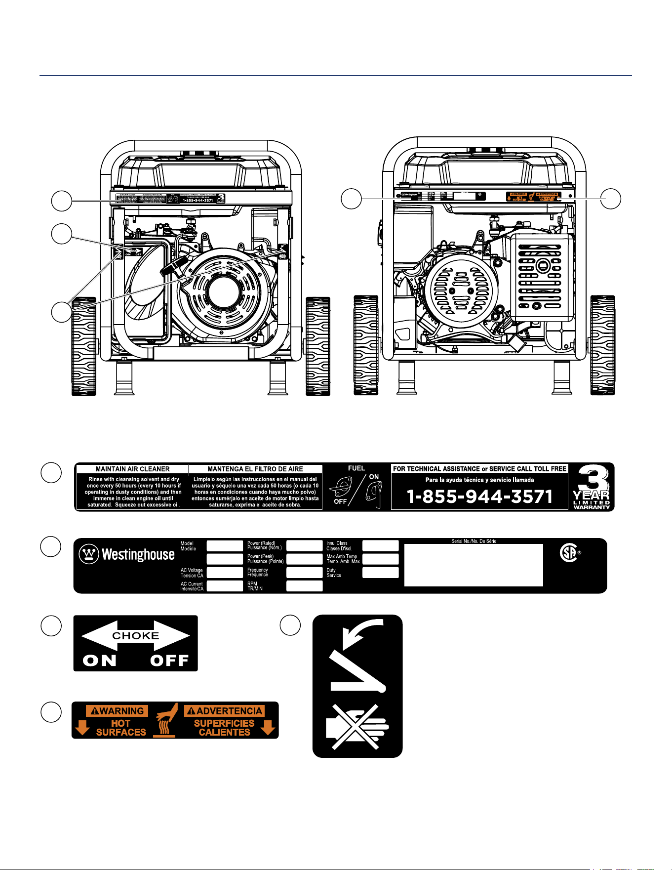
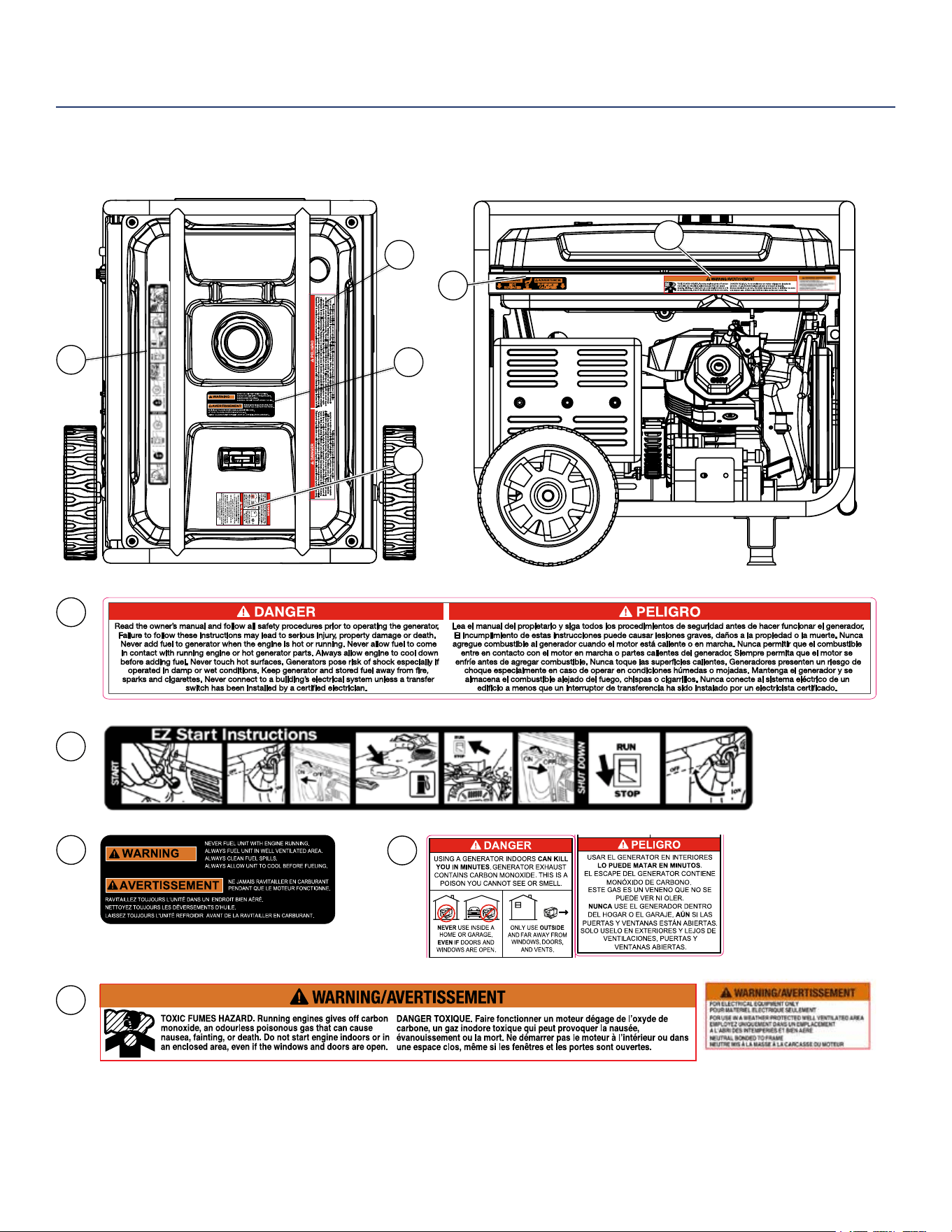
SAFETY
SAFETY LABELS AND DECALS
4
1
1
3
4
2
Made in China/
Fabriqu é en Chine
MWE Investments LLC
Columbus Ohio 43228 USA
Con u à columbus , Ohio,tats-Unis
MWE Investments LLC
Columbus Ohio 43228 Etats-Unis
Par t N0.
Numéro de
pièc e
Designed in Columbus , Ohio USA
4
2
5
5
3
Made in China/ Fabriqu é en Chine
CSA Master Contract
Number :
Numéro de contrat
principa l de CS A
MWE Investments LLC
Columbus Ohio 43228 USA
Con u à columbus , Ohio,tats-Unis
MWE Investments LLC
Columbus Ohio 43228 Etats-Unis
Par t N0.
Numéro de
pièc e
Designed in Columbus , Ohio USA
8 | Westinghouse Portable Power
SAFETY
SAFETY LABELS AND DECALS
8
7
10
8
9
6
6
7
5
10
9
Westinghouse Portable Power | 9
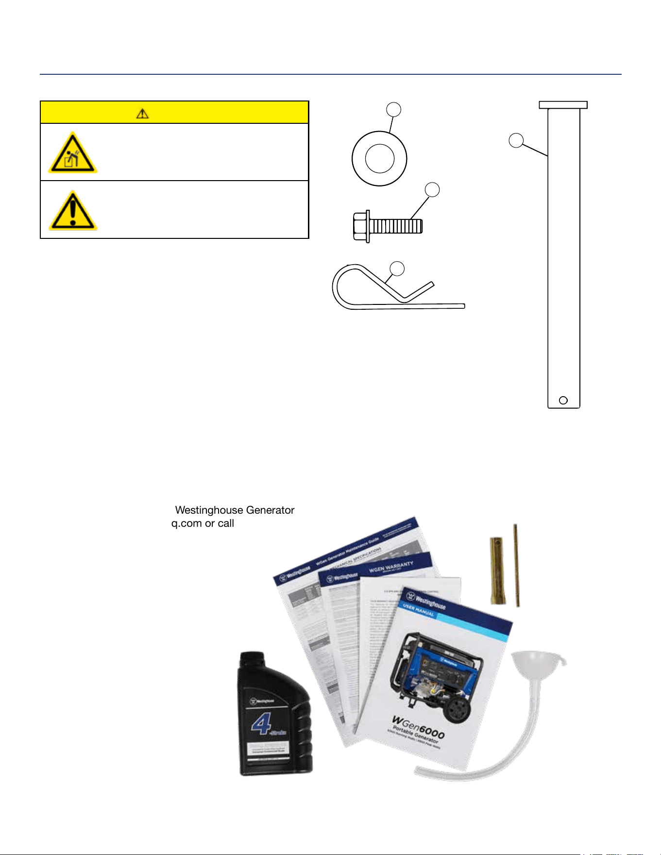
1. Washer (2 used)
2. Flange Bolt M8 x16mm (4 used)
3. Hairpin Cotter Pin (2 used)
4. Wheel Axle Pin (2)
CAUTION
Always have assistance when lifting
the generator. The generator is heavy;
lifting it could cause bodily harm.
Avoid cutting on or near staples
to prevent personal injury.
Tools required – box cutter or similar device.
1. Carefully cut the packing tape on top of the carton.
2. Fold back top aps to reveal the manual.
3. Remove the Wheel Kit Accessories cardboard box.
4. Carefully cut two sides of the carton to
remove the generator.
WHAT COMES IN THE BOX
Manual
Quick Start Guide/Maintenance Schedule
1.1 Liter Bottle of SAE 10W30 Oil (1)
Spark Plug Socket Wrench (1)
Wheel Kit Accessories Box
Funnel (1)
WHEEL KIT ACCESSORIES BOX
Open the Wheel Kit Accessories box and verify the
contents against the list right. If any parts are missing,
please locate an authorized Westinghouse Generator
dealer at service@wpowereq.com or call
1-855-944-3571.
UNPACKING
Wheel and Feet Kit Hardware
1
2
3
4
10 | Westinghouse Portable Power
INSTALLING WHEELS AND FEET
BEFORE ASSEMBLING THE
GENERATOR, REVIEW THE SAFETY
SECTION STARTING ON PAGE 5.
CAUTION
Never lift the generator without
assistance. The generator is heavy
and lifting without assistance could
result in personal injury.
Never use the handles as a lifting point to
support the entire weight of the generator.
Only use the handles to move the
generator by lifting the handles and using
the wheels to move the generator.
Use caution when collapsing the handles.
Hands and ngers could get caught and
pinched.
NOTICE
Assembling the generator will require lifting the unit on
one side. Make sure all engine oil and fuel are drained
from the unit prior to assembling. Once assembled, the
wheel kit is not intended for on-road use. The wheel kit
is designed for use on this generator only.
INSTALLING FEET TO FRAME
1. Place generator on a at surface.
2. Place a piece of cardboard or other soft material to
tip the generator onto, to protect the frame paint and
prevent the generator from sliding. Tip the generator
onto the side.
3. Install the mounting feet to the frame using the M8
ange bolts included.
1 - Mounting Foot
2 - Flange Bolts M8
1
2
Figure 1 - Assemble Mounting Feet to Frame
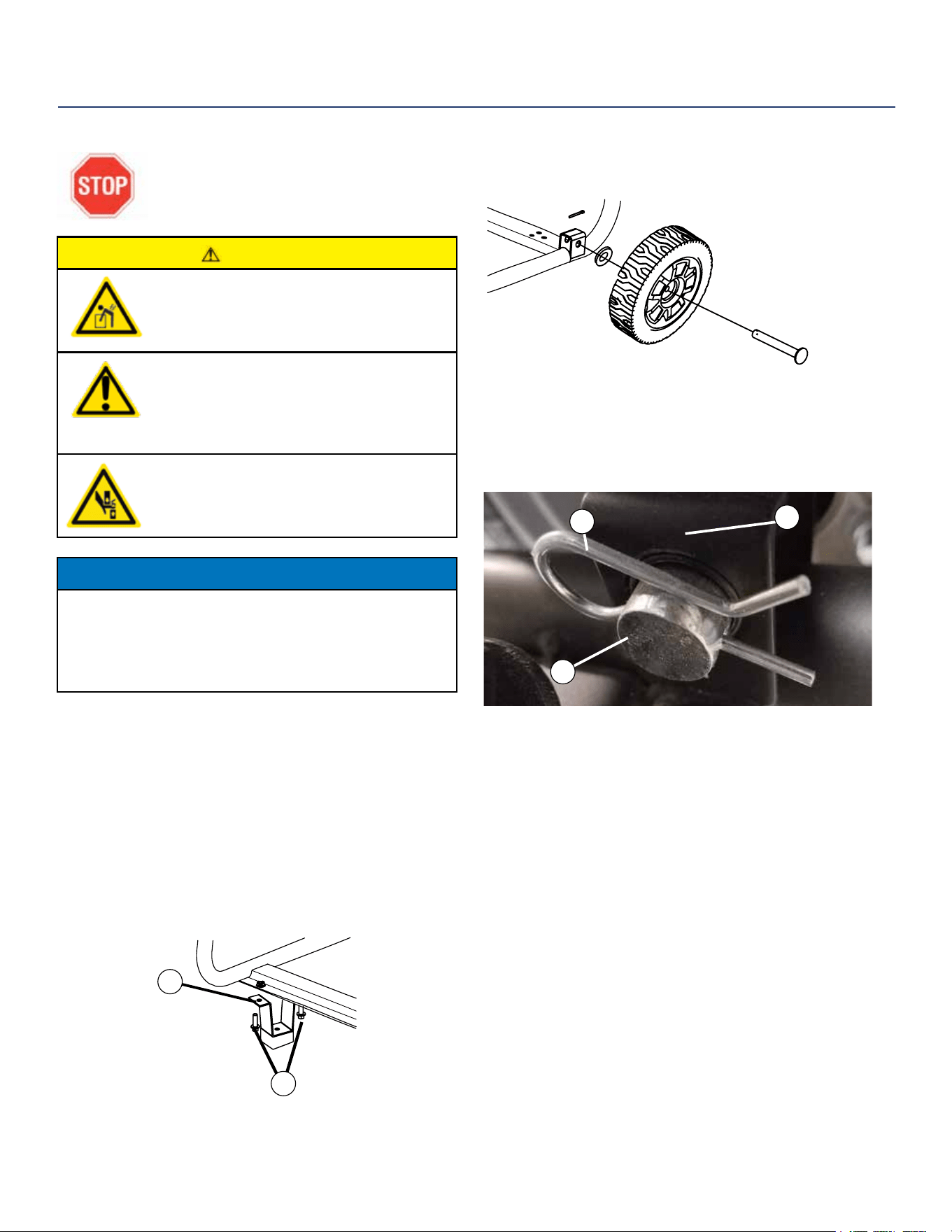
INSTALLING WHEELS TO FRAME
1. Insert axle pin through washer and wheel.
2. Install the wheel with axle pin through the axle
bracket on the frame. The eye of the bolt should be
facing toward the inside of the generator.
2
1
3
Figure 3 - Assemble Wheel to Frame
3. Install the hairpin cotter through the axle pin to lock it
in place.
1 - Axle Bracket
2 - Hairpin Clip
3 - Axle Pin
4. Repeat previous steps on other wheel.
ASSEMBLY
Figure 2 -Wheel Assembly
Westinghouse Portable Power | 11
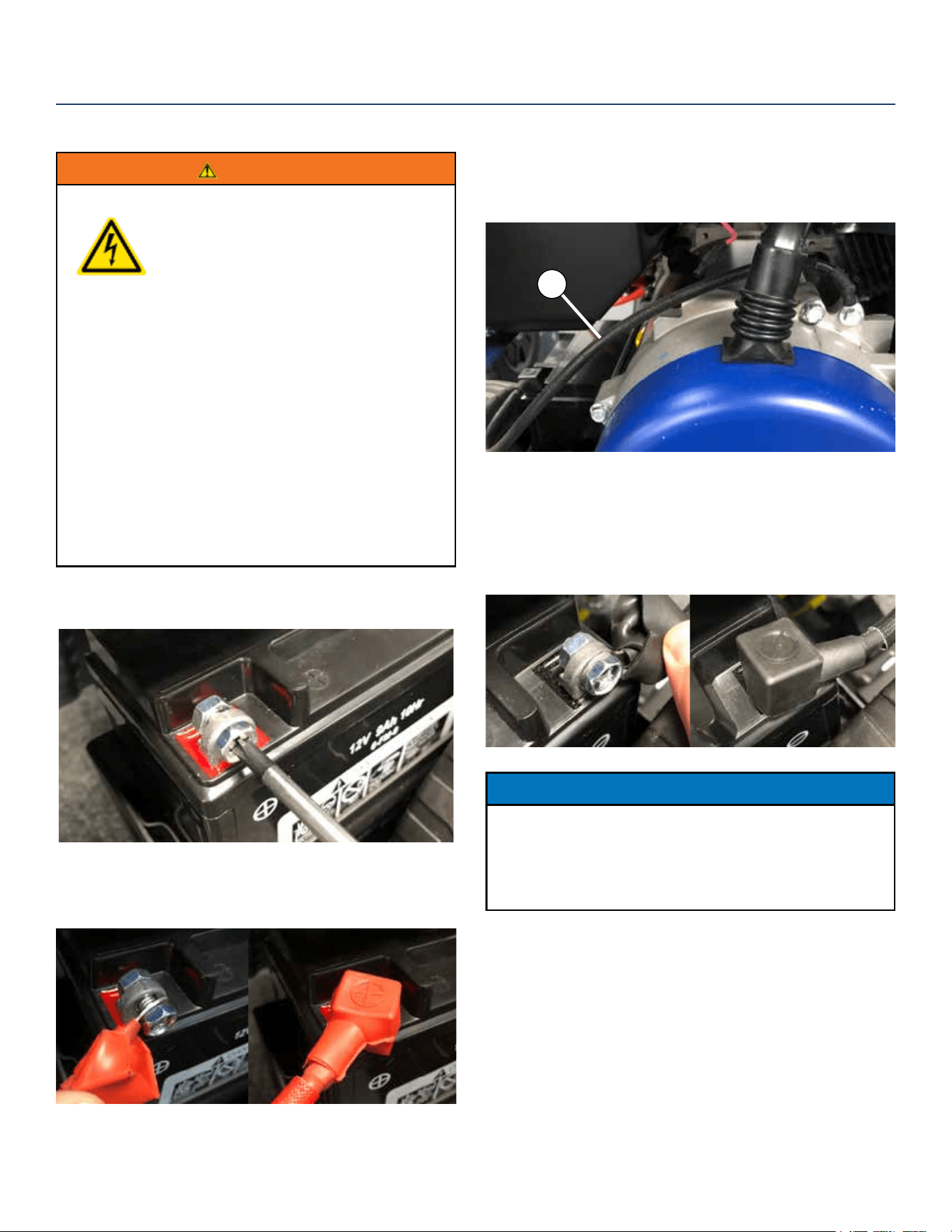
CONNECTING THE BATTERY
WARNING
To avoid electrics shock:
• ALWAYS connect the positive (+)
battery cable (red boot) rst when
connecting battery cables.
• ALWAYS disconnect the negative (-)
battery cable (black boot) rst when
disconnecting battery cables.
• NEVER connect the negative (-)
battery cable (black boot) to the
positive (+) post on the battery.
• NEVER connect the positive (+)
battery cable (red boot) to the
negative (-) post on the battery.
• NEVER touch both battery posts
simultaneously.
• NEVER place a metal tool across
both battery posts.
• ALWAYS use insulated or
nonconducting tools when installing
the battery.
1. Using a screw driver, remove the screw on the red
positive (+) battery lead.
2. Securely tighten the positive (+) battery cable (red
boot) to the positive (+) battery post. Make sure boot
is over battery post.
ASSEMBLY
3. Locate the black negative (-) cable attached to the
alternator case, route it to the negative (-) battery
post. See Figure 5 below for location (1) of negative (-)
cable.
1
Figure 5 - Locating Negative (-) Cable
4. Remove the screw on the negative (-) battery post. Pull
back the black boot and securely attach the negative
(-) battery cable (black boot) to the negative (-) battery
post and tighten screw. Replace the black boot so it
protects the cable lug and battery post.
NOTICE
The electric start generator is equipped with a battery
charging feature. Once the engine is running, a small
charge is supplied to the battery via the battery cables
and will slowly recharge the battery.
12 | Westinghouse Portable Power
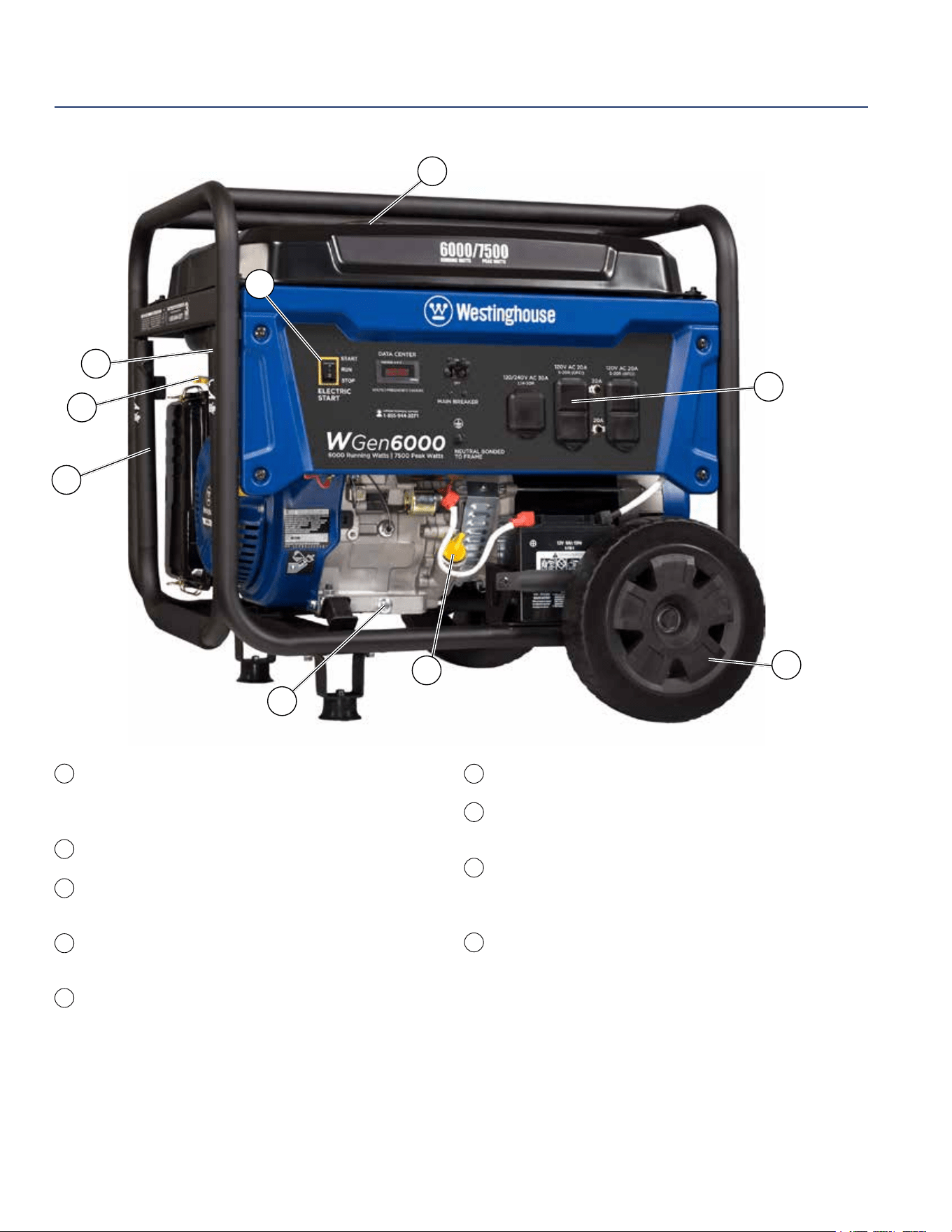
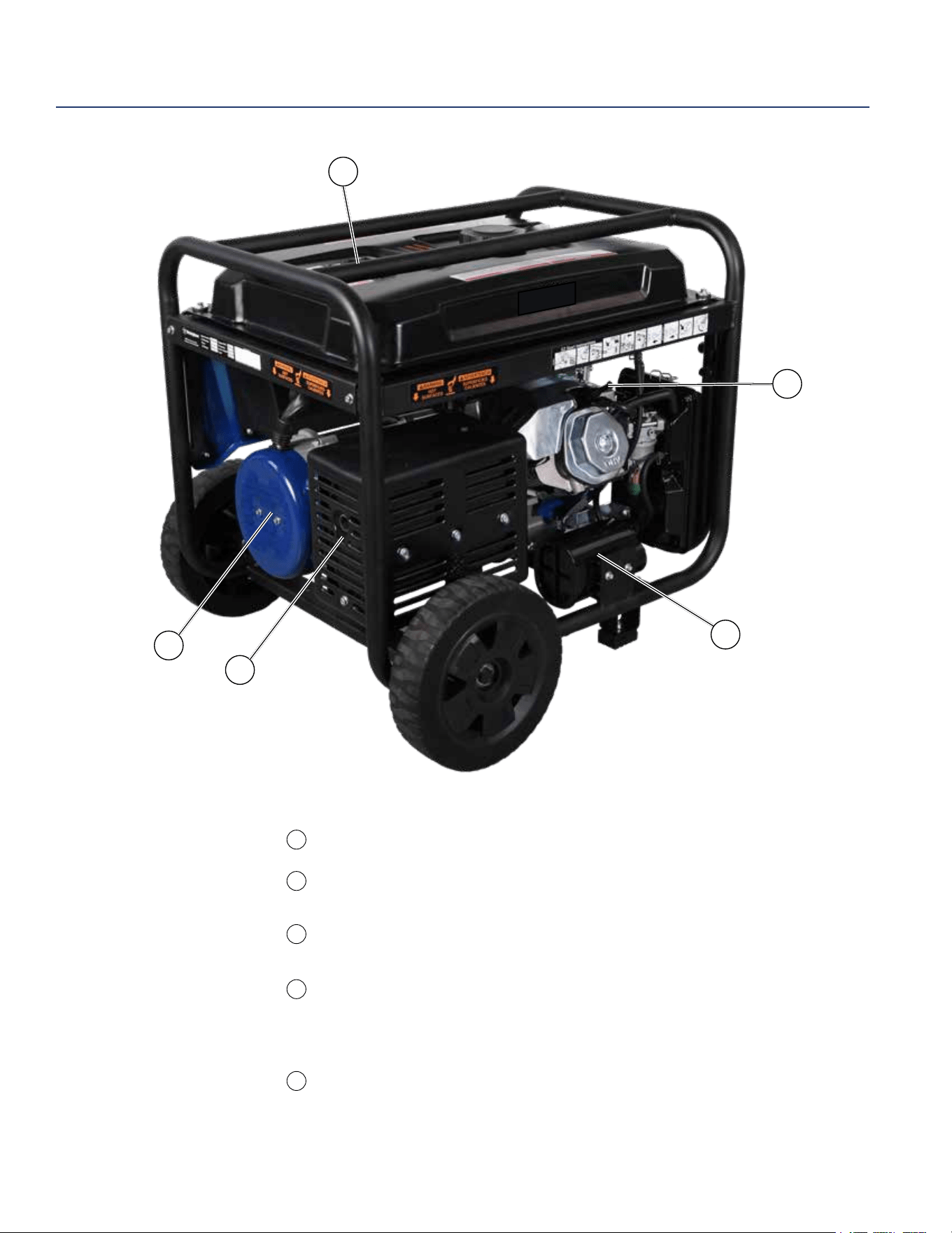
Electric Start Switch: Hold in Start position
for 1 second to start engine. Make sure to
manually open choke prior to cold starting.
Fuel Cap: Close until clicking sound is heard.
Control Panel: Contains the circuit breakers
and outlets.
Oil Fill Plug/Dipstick: Must be removed to add
and check oil.
Oil Drain Plug: Must be removed to drain
engine oil
FEATURES
Never Flat Wheels: For easy portability
Fuel Shut o Valve: Controls the ow of fuel
to the engine.
Manual Choke: Choke must be set manually by
adjusting choke lever. Move to ON position for cold
starting.
Single Piece Handle: Includes rubber grip. Allows
you to easily push or pull unit with one hand.
1
5
6
7
8
9
2
3
4
1
3
5
4
9
8
7
6
2
Westinghouse Portable Power | 13
FEATURES
Fuel Gauge: Indicates fuel level.
Spark Plug Boot (Wire): Must be removed when
servicing the engine or the spark plug.
CARB Canister: Required for models sold into and
used in California.
Muer and Spark Arrester: Avoid contact until
engine is cooled down. Spark arrestor prevents
sparks from exiting the muer. It must be removed
for servicing.
Alternator Cover: Gain access to alternator wiring.
10
11
13
14
10
11
12
13
14
12
14 | Westinghouse Portable Power
START
RUN
STOP
NEUTRALŁ
BONDED TOŁ
FRAME
ELECTRICŁ
START
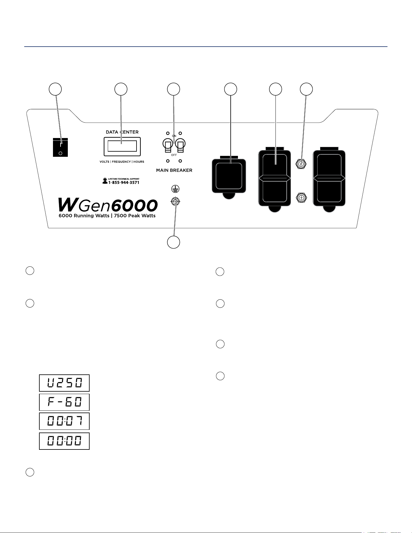
120/240-Volt, 30-Amp Twist Lock Outlet
(NEMA L14-30R): Outlet can supply either
120V or 240V output.
120-Volt, 20-Amp Duplex GFCI Outlets
(NEMA 5-20R): Each outlet is capable of carrying
a maximum of 20 amps on a single receptacle or
a combination of both receptacles.
20-Amp Circuit Breakers: Each circuit breaker
limits the current that can be delivered through
the 120-volt duplex outlets to 20amps.
Ground Terminal: The ground terminal is used to
ground the generator.
Electric Start Switch: Hold in START position until
engine starts. Make sure to set choke prior to cold
starting.
Data Center: The VFT Meter is 4 state LED display
that will rotate through volts, frequency, and lifetime
run hours. The 4th display is not used and will
always display 00:00. You can press the MODE
button to cycle through the dierent displays. The
meter will display volts and hertz even if there is no
load connected.
The frequency and voltage can vary +/- 5% and
still be within tolerance.
Frequency in hertz
Lifetime run hours
Inoperative
Voltage
Main Circuit Breaker: The main circuit breaker
controls total output of all outlets to protect the
generator.
CONTROL PANEL FEATURES
1
6
7
2
3
4
5
1
7
FEATURES
120/240V AC 30AŁ
L14-30R
120V AC 20AŁ
5-20R (GFCI)
120V AC 20AŁ
5-20R (GFCI)
20A
20A
3 42 5 6
Westinghouse Portable Power | 15
No Connected Loads – Make sure the generator has no
connected loads before starting it. To ensure there are no
connected loads, unplug any electrical extension cords that
are plugged into the control panel receptacles.
NOTICE
Starting the generator with loads already applied to it could result in
damage to any appliance being powered o the generator during the
brief start-up period.
Grounding the Generator – The National Electric Code
(NEC), as well as many local electrical codes, may require
the generator to be connected to earth ground. The most
common application that requires a ground rod is when you
are using the generator as a separately derived system to
provide back up power to your house. Typically this is when a
transfer switch has a switched neutral.
As the generator application has many variables that cannot
be determined by the manufacturer of the generator, a
licensed electrician will need to determine if a grounding rod is
needed.
If a licensed electrician has determine the application requires
a ground rod, make sure it is connected to earth ground by
connecting the ground terminal on the control panel to earth
ground using copper wire (minimum 10 AWG). Consult a
qualied electrician for local grounding requirements.
Neutral Bonded: There is a permanent conduct or between
the generator (stator winding) and the frame.
WARNING
Be sure the generator is properly connected to
earth ground before operating. The generator
must be grounded to prevent electrical shock
due to faulty appliances.
High Altitude Operation
Engine power is reduced the higher you operate above sea
level. Output will be reduced approximately 3.5% for every
1000ft of increased altitude from sea level. This is a natural
occurrence and cannot be adjusted by engine. Increased
exhaust emissions can also result due to increased fuel
mixture. Other issues include hard starting, increased fuel
consumption and spark plug fouling. Contact our service
team 1-855-944-3571 for altitude part kits.
High Altitude Carburetor Kit Part Number: 140545
BEFORE STARTING THE GENERATOR
BEFORE STARTING THE GENERATOR,
REVIEW SAFETY SECTION STARTING ON
PAGE 5.
Location Selection – Before starting the generator, avoid
exhaust and location hazards by verifying:
• You have selected a location to operate the generator
that is outdoors and well ventilated.
• You have selected a location with a level and solid
surface on which to place the generator.
• You have selected a location that is at least 15 feet
(4.5 m) away from any building, other equipment or
combustible material.
• If the generator is located close to a building, make
sure it is not located near any windows, doors and/or
vents.
WARNING
Always operate the generator on a level surface.
Placing the generator on non level surfaces can
cause the generator to tip over, causing fuel and
oil to spill. Spilled fuel can ignite if it comes in
contact with an ignition source such as a very hot
surface.
NOTICE
Only operate the generator on a solid, level surface. Operating the
generator on a surface with loose material such as sand or grass
clippings can cause debris to be ingested by the generator that
could:
• Block cooling vents
• Block air intake system
Weather – Never operate your generator outdoors during
rain, snow or any combination of weather conditions that
could lead to moisture collecting on, in or around the
generator.
Dry Surface – Always operate the generator on a dry
surface free of any moisture.
OPERATION
16 | Westinghouse Portable Power
POWERCORD
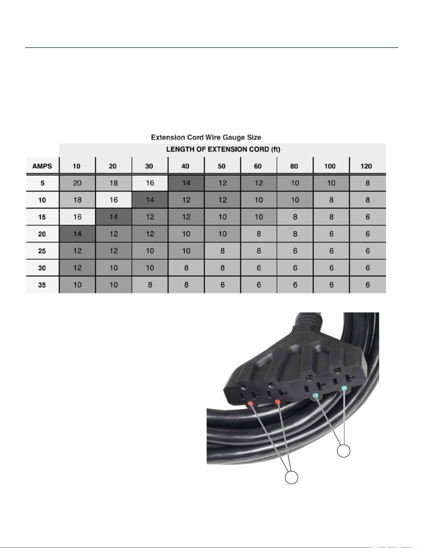
Using Extension Cords
Westinghouse Portable Power assumes no responsibility for the content within this table. The use of this table is the
responsibility of the user only. This table is intended for reference only. The results produced by using this table are
not guaranteed to be correct or applicable in all situations as the type and construction of cords are highly variable.
Always check with local regulations and a licensed electrician prior to installing or connecting an electrical appliance
Using Westinghouse Power Cord
Use the extension cord chart to determine the size
of the conductor for extension cord applications.
Determine the distance of the generator to the
appliance on the top line of the chart. Then select the
rated amperage of the generator on the left side of the
chart. Where the two meet is the size of the conductor
required for the application.
The WCG25 power cord is connected to the generator
at the 120/240 plug. The opposite end of the power
cord is a fan tail receptacle with 2 green receptacles
and 2 red receptacles. Each receptacle is rated at
120 volts AC. To balance the load on the generator’s
alternator, use the red and green identiers on the fan
tail receptacle. To keep the load balanced, connect
the loads so that both color receptacles are used. An
example is one in red and one in green. Do not connect
2 in red and none in green, or 2 in green and none in
red. If only one color receptacle is used with multiple
loads, the alternator may experience an unbalanced
load, causing undue vibration to generator.
OPERATION
1
2
- WCG25/WCG20 Extension Cord
Red Dots
Green Dots
Westinghouse Portable Power | 17
ADDING / CHECKING ENGINE
FLUIDS AND FUEL
BEFORE ADDING/CHECKING ENGINE
FLUIDS AND FUEL, REVIEW SAFETY
SECTION STARTING ON PAGE 5.
DANGER
Filling the fuel tank with gasoline while
the generator is running can cause
gasoline to leak and come in contact
with hot surfaces that can ignite the
gasoline.
Before starting the generator, always check the level of:
• Engine oil
• Gasoline in the fuel tank
Once the generator is started and the engine gets warm,
it is not safe to add gasoline to the fuel tank or engine oil
to the engine while the engine is running or the engine and
muer are hot.
CHECKING AND / OR ADDING ENGINE OIL
WARNING
Internal pressure can build in the engine
crankcase while the engine is running.
Removing the oil ll plug/ dipstick while
the engine is hot can cause extremely
hot oil to spray out of the crankcase and
can severely burn skin. Allow engine
oil to cool for several minutes before
removing the oil ll plug/dipstick.
The unit as shipped does not contain oil in the engine. You
must add engine oil before starting the generator for the
rst time. See Checking Engine Oil and Adding Engine Oil
on page 24 for instructions on checking engine oil level
and the procedure for adding engine oil.
NOTICE
The engine does not contain engine oil as shipped.
Attempting to start the engine can damage engine
components. The owner of the generator is responsible
to ensure the proper oil level is maintained during the
operation of the generator. Failure to maintain the proper
oil level can result in engine damage.
OPERATION
CONNECTING THE GENERATOR TO A
BUILDING ELECTRICAL SYSTEM
It is recommended to use a manual transfer switch when
connecting directly to a buildings electrical system.
Connecting a portable generator to a buildings electrical
system must be made in strict compliance with all
national and local electrical codes and laws, and be
completed by a qualied electrician.
TRANSFER SWITCH CONNECTIONS
The Westinghouse generator is wired with the neutral
bonded to ground. If you are connecting your generator
to a panel board transfer switch, a licensed electrician
will need to consider removing the bonded neutral to
ensure proper operation of household GFCI circuits.
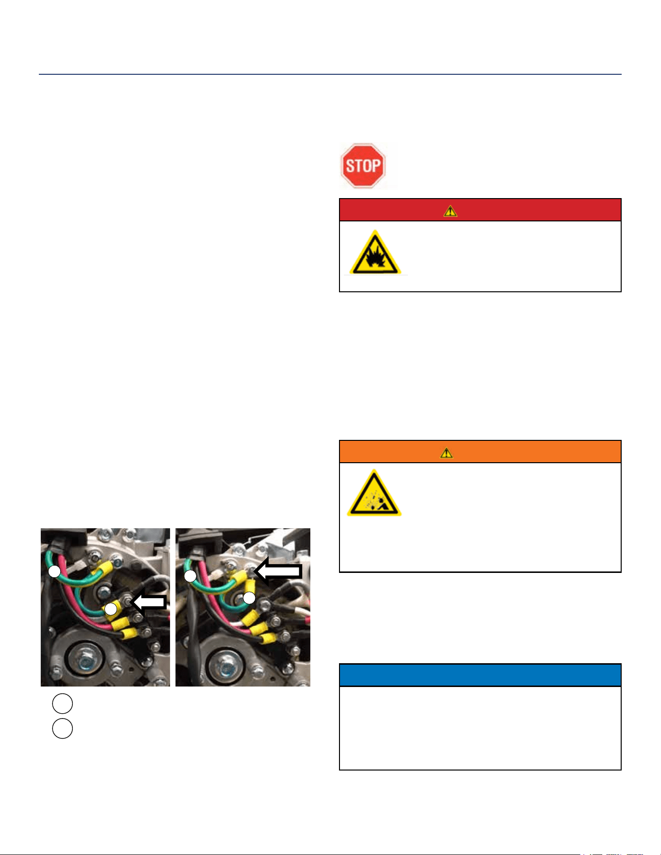
Begin by removing the alternator cover (14 on page
13). Once the cover is o remove the nut that holds the
bonded ground jumper wire (see “2” in Figure 6). Once
the nut is removed take the bonded jumper wire o and re-
secure the nut. Next remove the screw holding the neutral
ground wire (see “1” in Figure 6). Attach the bonded jumper
wire (2) to the neutral ground (1) and tighten the screw.
If the bonded neutral is removed the generator must be
relabeled as oating neutral on the control panel.
If your generator is equipped with GFCI receptacles,
removing the bonded neutral may not allow proper
operation of the GFCI receptacles. Always keep the
jumper wire in case it is needed for future use when not
connected to a transfer switch.
1
1
1
2
2
2
Figure 6
REMOVE
MOVE WIRE HERE
Alternator Neutral Ground Wire (white/Green)
Alternator Bonded Jumper Wire (white/Green)
18 | Westinghouse Portable Power
ADDING GASOLINE TO THE FUEL TANK
WARNING
Never refuel the generator while the
engine is running.
Always turn the engine o and allow
the generator to cool before refueling.
Required Gasoline – Only use gasoline that meets the
following requirements:
• Unleaded gasoline only
• Gasoline with maximum 10% ethanol added
• Gasoline with an 87 octane rating or higher
Filling the Fuel Tank – Follow the steps below to ll the
fuel tank:
1. Shut o the generator.
2. Allow the generator to cool down so all surface areas
of the muer and engine are cool to the touch.
3. Move the generator to a at surface.
4. Clean area around the fuel cap.
5. Remove the fuel cap by rotating counterclockwise.
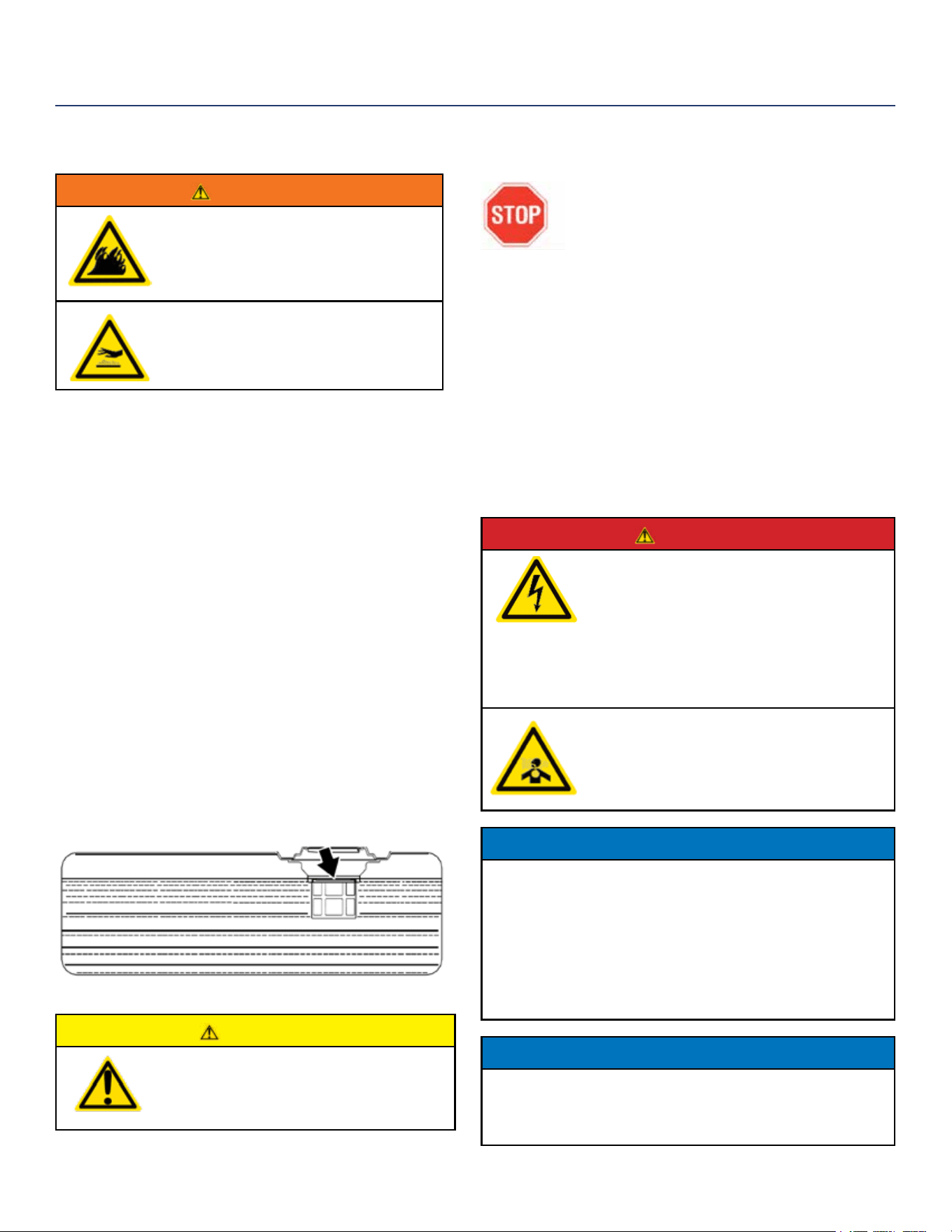
6. Slowly add gasoline into the fuel tank. Be very careful
not to overll the tank. The gasoline level should NOT
be higher than the ller neck (see Figure 7).
7. Install the fuel cap by rotating clockwise until
you hear a click, indicating the cap is completely
installed.
Figure 7 - Maximum Gasoline Fill Level
CAUTION
Avoid prolonged skin contact with
gasoline. Avoid prolonged breathing of
gasoline vapors.
BEFORE STARTING THE GENERATOR
BEFORE STARTING THE GENERATOR,
REVIEW SAFETY SECTION STARTING ON
PAGE 5.
Before attempting to start the generator,
verify the following:
• The engine is lled with engine oil. See Checking Engine
Oil on page 24.
• The generator is situated in a proper location (Location
Selection on page 15).
• The generator is on a dry surface (Weather and Dry
Surface on page 15).
• All loads are disconnected from the generator (No
Connected Loads on page 15).
• The generator is properly grounded (page 15).
DANGER
Never use the generator in a location
that is wet or damp. Never expose the
generator to rain, snow, water spray or
standing water while in use. Protect the
generator from all hazardous weather
conditions. Moisture or ice can cause a
short circuit or other malfunction in the
electrical circuit.
Never operate the generator in an
enclosed area. Engine exhaust contains
carbon monoxide. Only operate the
generator outside and away from
windows, doors and vents.
NOTICE
The engine is equipped with a low oil shutdown switch. If the
oil level becomes low, the engine may shut down and not start
until the oil is lled to the proper level. Poor oil quality may
interfere with the operation of the low oil shutdown switch.
The owner of the generator is responsible to ensure the proper
oil level is maintained during the operation of the generator.
Failure to maintain the proper oil level can result in engine
damage.
NOTICE
DO NOT connect 240V loads to a 120V receptacles. DO NOT
connect 3-phase loads to the generator. DO NOT connect 50Hz
loads to the generator. Let engine stabilize and warm up for a
few minutes before adding load.
OPERATION

Westinghouse Portable Power | 19
OPERATION
POWER OUTPUT AND DEMAND
The generator should not be run completely unloaded for extended periods otherwise the engine may be
damaged. It is recommended that the generator should always be operated with at least one-third of its
rated 120-Volt AC power output. 120-Volt AC devices have two dierent electric power demands that must
be taken into consideration, namely the running power and the starting/peak power. Both are measured in
Watts (typically abbreviated as “W”).
The steady state continuous load is the running power demand and this is often marked on the device near
its model number or serial number. Sometimes the device might only be marked with its voltage (i.e. 120 V)
and current draw (e.g. 6 Amp or 6 A), in which case the running power demand in Watts can be obtained by
multiplying the voltage times the current, e.g. 120 V × 20 A = 2,400 W.
Simple resistive 120-Volt AC devices such as incandescent bulbs, toasters, heaters, etc. have no extra power
demand when starting, and so their starting power demands are the same as their running power demands.
More complex 120-Volt AC devices containing inductive or capacitive elements such as electric motors have a
momentary extra power demand when starting, which can be up to seven times the running power demand or
more. Manufacturers of such devices rarely publish this starting power demand and so it’s often necessary to
estimate it. A rule of thumb for devices tted with an electric motor is to apply a starting power multiplier of 1.2
for small hand-held or portable devices and a value of 3.5 for larger stationary devices. For example, a 900 W
angle grinder can be assumed to have a starting power demand of at least 1.2 × 900 W, which equals 1,080 W.
Similarly, a 1,650 W air compressor can be assumed to have a starting power demand of at least 3.5 × 1,650 W,
which equals 5,775 W.
To prevent overloading of the generator’s 120-Volt AC system:
1. Add up the running power demand of all the 120-Volt AC devices that will be connected to the generator at
one time. This total must not be greater than the generator’s specied running power output.
2. Add up the running power demand again, but for the largest motor-driven device use the value of its starting
power demand instead of its running power demand. This total must not be greater than the generator’s
specied starting power output.
3. The total running power demand of all the devices that will be connected to any one of the generator’s
outlets must not exceed the generator’s specied running power output or 3,700 W, whichever is the lesser.
20 | Westinghouse Portable Power
STARTING THE GENERATOR
Be sure to check oil levels before starting. If it is the rst
time starting make sure to add oil (see Adding Engine Oil
page 24).
1. Make sure nothing is plugged into power outlets.
2. Verify the battery is installed and both battery
cables are attached to their corresponding polarity.
(See Installing the Battery on page 11)
3. Make sure the circuit breakers are properly set (see
Figure 8 below).
Figure 8 - Breakers
1
240/120VMain Circuit Breaker Operating Position
2
240/120V Main Circuit Breaker Tripped Position
3
120V Circuit Breaker Operating Position
4
120V Circuit Breaker Tripped Position
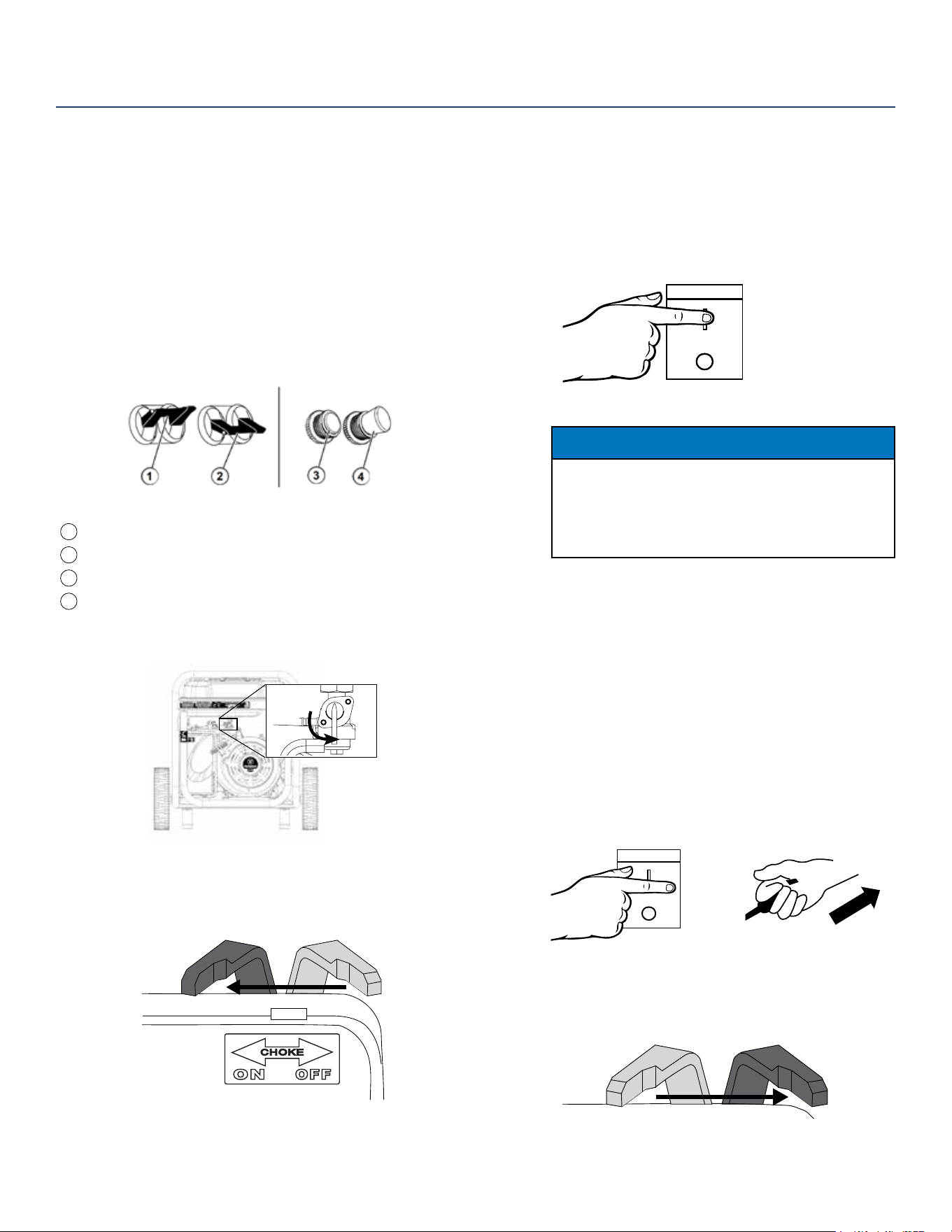
4. Move the fuel shut o valve to the ON position (see
Figure 9 below).
ON
OFF
Figure 9 - Fuel Shut O - ON
5. For cold starting move the choke lever to the ON
position (see Figure 10 below). If warm starting move
choke to OFF position.
Figure 10 - Cold Start Choke Lever - ON
6. Choose starting method:
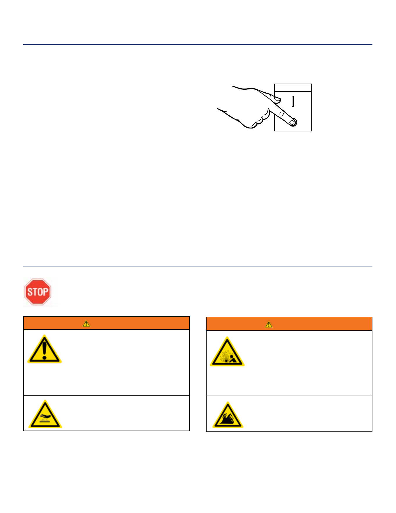
a. Electric Start: Push and hold the engine control
switch in the START position until the engine
starts. Once the engine starts, release the engine
control switch; the switch will automatically move
into the RUN position (see Figure 11 below).
START
RUN
STOP
Figure 11 - Engine Control Switch - START
NOTICE
Failure to release the engine control switch once the engine
starts could result in damage to the generator.
Never push the engine control switch to the START
position while the engine is running’ this could damage the
generator.
Note: If the engine fails to start after 5
seconds, release the engine control switch.
Let the generator sit idle for 15 seconds and
then repeat step 8. If the cranking speed
drops after each unsuccessful attempt, then
the battery may not be adequately charged.
Manually start the generator by following
steps below:
b. Manual Start: Make sure the engine control
switch is in the RUN position. Firmly grasp
and pull the recoil handle slowly until you feel
increased resistance. At this point, apply a rapid
pull while pulling up and slightly away from the
generator.
START
RUN
STOP
Figure 12 - Cold Start Choke Lever - OFF
7. After cold starting, as the engine starts and stabilizes,
gradually move the choke lever back to the OFF
position (see Figure 13 below).
Figure 13 - Cold Start Choke Lever - OFF
8. Plug in electric devices.
OPERATION
Westinghouse Portable Power | 21
STOPPING THE GENERATOR
Normal Operation
During normal operation, use the following steps to stop
your generator:
1. Remove any connected loads from the control panel
receptacles.
2. Allow the generator to run at “no load” to reduce and
stabilize engine and alternator temperatures.
3. Position the engine control switch to STOP or if you
plan to store the generator after use, turn the fuel
shuto valve to the OFF position and allow the fuel to
be consumed from the carburetor (see Figure 14).
During an Emergency
If there is an emergency and the generator must be
stopped quickly, position the engine control switch to the
STOP position immediately.
WARNING
Internal pressure can build in the engine
crankcase while the engine is running.
Removing the oil ll plug/ dipstick while
the engine is hot can cause extremely
hot oil to spray out of the crankcase and
can severely burn skin. Allow engine
oil to cool for several minutes before
removing the oil ll plug/dipstick.
Always perform maintenance in a well-
ventilated area. Gasoline fuel and fuel
vapors are extremely ammable and
can ignite under certain conditions.
WARNING
Avoid accidentally starting the generator
during maintenance by removing the
spark plug boot from the spark plug.
For electric start generators, also
disconnect the battery cables from the
battery (disconnect the black negative
(-) cable rst) and place the cables away
from the battery posts to avoid arcing.
Allow hot components to cool to
the touch prior to performing any
maintenance procedure.
OPERATION
MAINTENANCE
Figure 14 - Move engine switch to STOP
BEFORE PERFORMING MAINTENANCE ON THE GENERATOR, REVIEW THE
SAFETY SECTION STARTING ON PAGE 5, AS WELL AS THE FOLLOWING
SAFETY MESSAGES.
START
RUN
STOP
22 | Westinghouse Portable Power
MAINTENANCE SCHEDULE
WARNING
Failure to perform periodic maintenance
or not following maintenance procedures
can cause the generator to malfunction
and could result in death or serious injury.
NOTICE
Periodic maintenance intervals vary depending on
generator operating conditions. Operating the generator
under severe conditions, such as sustained high-
load, high-temperature, or unusually wet or dusty
environments, will require more frequent periodic
maintenance. The intervals listed in the maintenance
schedule should be treated only as a general guideline.
MAINTENANCE
TABLE 1: MAINTENANCE SCHEDULE - OWNER PERFORMED
Maintenance Item
Before Every
Use
After First 20
Hours or First
Month of Use
After 50 Hours
of Use or Every
6 Months
After 100 Hour
of Use or Every
6 Months
After 300 Hours of
Use or Every Year
Engine Oil
Check Level Change Change - -
Cooling Features
Check/Clean - - - -
Air Filter
Check - Clean* - Replace
Spark Plug
- - - Check/Clean Replace
Spark Arrestor
- - - Check/Clean -
*Service more frequently if operating in dry and dusty conditions
TABLE 2: MAINTENANCE SCHEDULE - AUTHORIZED WESTINGHOUSE
SERVICE DEALER PERFORMED
Maintenance Item
Before Every
Use
After First 20
Hours or First
Month of Use
After 50 Hours
of Use or Every
6 Months
After 100 Hour
of Use or Every
6 Months
After 300 Hours of
Use or Every Year
Valve Clearance
- - - - Check/Adjust
Fuel Filter
- - - Check/Clean -
CAUTION
Avoid skin contact with engine
oil or gasoline. Prolonged
skin contact with engine oil
or gasoline can be harmful.
Frequent and prolonged contact
with engine oil may cause
skin cancer. Take protective
measures and wear protective
clothing and equipment. Wash
all exposed skin with soap and
water.
Following the maintenance schedule is important
to keep the generator in good operating condition.
The following is a summary of maintenance items by
periodic maintenance intervals.
Westinghouse Portable Power | 23
MAINTENANCE
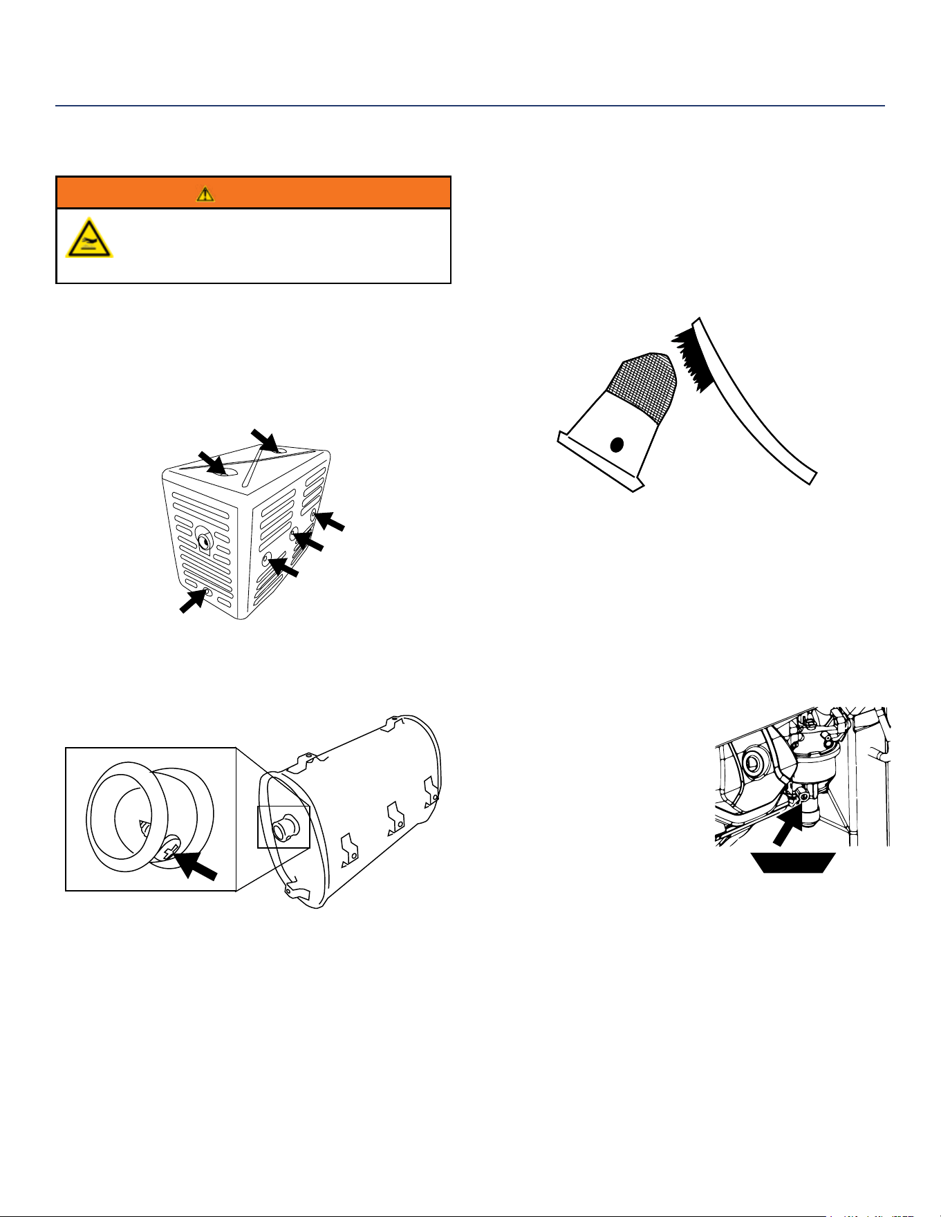
CLEANING THE SPARK ARRESTOR
WARNING
Hot Surfaces. When operating machine, do not
touch hot surfaces. Keep machine away from
combustibles during use. Hot surfaces could
result in severe burns or re.
Check and clean the spark arrestor after every 100 hours
of use or 6 months.
1. Generator must be cold to perform this maintenance.
2. Move the inverter to a at, level surface.
3. Remove the 6 screws holding the muer cover in
place (see Figure 15).
Figure 15: Remove screws holding muer cover
4. Once the cover is removed, locate the screw on the
tip of the muer and remove. Pull the spark arrestor
out of the muer. (see Figure 16).
Figure 16: Remove spark arrestor
5. If the spark arrestor screen shows signs of wear (rips,
tears or large openings in the screen), replace the
spark arrestor screen. NOTE: Only use Westinghouse
spark arrestors as replacements.
6. If screen is not torn then clean using a wire brush,
commercial solvent, or compressed air. Remove any
dirt and debris that may have collected on the spark
arrestor screen (see Figure 17).
Figure 17: Clean spark arrestor
7. Install the spark arrestor back into the muer. Make
sure to fully push it in so that it is tight on the tip of
the muer.
8. Replace the muer cover and tighten all 6 screws.
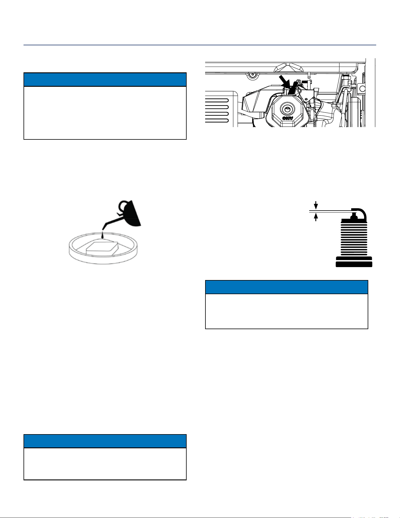
DRAINING CARBURETOR FLOAT BOWL
1. Make sure the generator is o and you are away from
any open ames.
2. Place pan (or suitable
container) under the
carburetor assembly.
3. Loosen screw at bottom of
the bowl and allow gas to
drain out.
4. After all the gas has drained
out, tighten the screw.
fuel pan
24 | Westinghouse Portable Power
ENGINE OIL MAINTENANCE
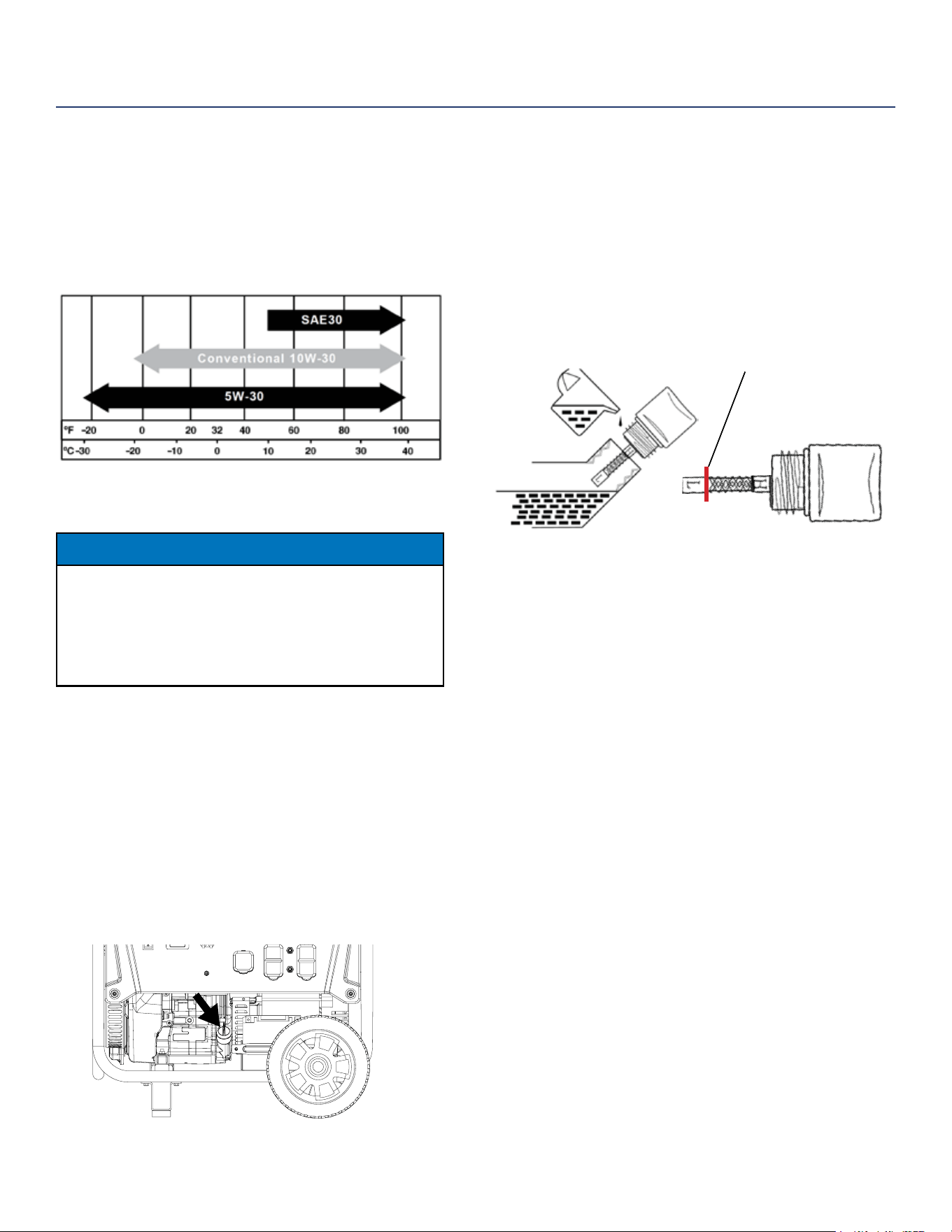
Engine Oil Specication
1. Only use the engine oil specied in Figure 18.
2. Only use 4-stroke/cycle engine oil. NEVER USE
2-STROKE/CYCLE OIL. Synthetic oil is an
acceptable substitute for conventional oil.
Figure 18 - Recommended Oil
CHECKING ENGINE OIL
NOTICE
Always maintain proper engine oil level. Failure to
maintain proper engine oil level could result in severe
damage to the engine and/or shorten the life of the
engine. Always use the specied engine oil. Failure
to use the specied engine oil can cause accelerated
wear and/or shorten the life of the engine.
Engine oil level should be checked before every use.
1. Always operate or maintain the generator
on a at surface.
2. Stop engine if running.
3. Let engine sit and cool for several minutes (allow
crankcase pressure to equalize).
4. With a damp rag, clean around the
oil ll plug/dipstick.
5. Remove oil ll plug/dipstick (see Figure 19 below).
Figure 19 - Oil Fill Plug/Dipstick
6. Check oil level: When checking the engine oil,
remove the oil ll plug/dipstick and wipe it clean.
Thread the oil ll plug/dipstick all the way back in and
then remove and check the oil level on the oil ll plug/
dipstick.
• Acceptable Oil Level – Oil is visible on the
crosshatches between the H and L lines on the oil
ll plug/dipstick (see Figure 20).
• Low Oil – Oil is below the L line on the oil ll plug/
dipstick.
If oil level is below
this line it is too
low to operate.
Figure 20 - Checking Oil Level
ADDING ENGINE OIL
1. Always operate or maintain the generator
on a at surface.
2. Stop engine if running.
3. Let engine sit and cool for several minutes (allow
crankcase pressure to equalize).
4. Thoroughly clean around the oil ll plug/dipstick.
5. Remove oil ll plug/dipstick and wipe clean.
6. Select the proper engine oil as specied
in Figure 18.
7. Using the supplied funnel, slowly add engine oil to
the engine. Stop frequently to check the level to
avoid overlling.
8. Continue to add oil until the oil is at the correct level.
See Figure 20.
9. Replace the oil ll plug/dipstick.
MAINTENANCE
Westinghouse Portable Power | 25
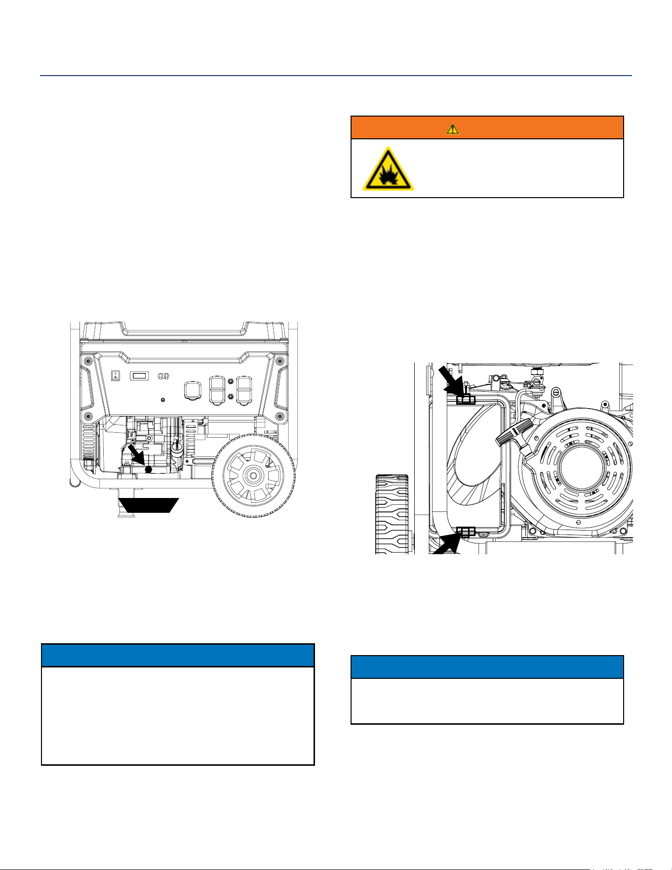
AIR FILTER MAINTENANCE
WARNING
Never use gasoline or other ammable
solvents to clean the air lter. Use only
household detergent soap to clean the
air lter.
Cleaning the Air Filter
The air lter must be cleaned after every 50 hours of use
or 3 months (frequency should be increased if generator
is operated in a dusty environment).
1. Turn o the generator and let it cool for several
minutes if running.
2. Move the generator to a at, level surface.
3. Unclip the clips on the top and bottom of the air lter
cover (Figure 22).
Figure 22 - Unclip air lter
4. Remove the black coarse air lters.
5. Wash the foam air lter elements by submerging
the elements in a solution of household detergent
soap and warm water. Slowly squeeze the foam to
thoroughly clean.
NOTICE
NEVER twist or tear the foam air lter element
during cleaning or drying. Only apply slow but rm
squeezing action.
6. Rinse in clean water by submerging the air lter
elements in fresh water and applying a slow
squeezing action
CHANGING ENGINE OIL
1. Always operate or maintain the generator
on a at surface.
2. Stop the engine.
3. Let engine sit and cool for several minutes (allow
crankcase pressure to equalize).
4. Place oil pan (or suitable container) under the oil
drain plug (see Figure 21).
5. With a damp rag, thoroughly clean around the oil
drain plug.
6. Remove the oil drain plug (see Figure 21). Once
removed, place the oil drain plug on a clean surface.
oil pan
Figure 21 - Oil Drain Plug
7. Allow oil to completely drain.
8. Replace oil drain plug.
9. Fill crankcase with oil following the steps outlined in
Adding Engine Oil on page 24.
NOTICE
Never dispose of used engine oil by dumping the
oil into a sewer, on the ground, or into ground
water or waterways. Always be environmentally
responsible. Follow the guidelines of the EPA or
other governmental agencies for proper disposal
of hazardous materials. Consult local authorities or
reclamation facility.
MAINTENANCE
26 | Westinghouse Portable Power
Cleaning the Air Filter - Continued from Page 25
NOTICE
Never dispose of soap cleaning solution used to clean
the air lter by dumping the solution into a sewer, on the
ground, or into ground water or waterways. Always be
environmentally responsible. Follow the guidelines of the
EPA or other governmental agencies for proper disposal
of hazardous materials. Consult local authorities or
reclamation facility.
7. Dispose of used soap cleaning solution properly.
8. Dry the air lter elements by again applying a slow
rm squeezing action.
9. Once the air lters are dry, coat the air lters with
clean engine oil.
10. Squeeze the lters to remove any excess oil.
11. Install the lters back into the unit. Make sure the
gray (ne) air lter goes in rst followed by the black
(coarse) air lter on the outside.
12. Install the air lter cover and secure the air lter assembly.
SPARK PLUG MAINTENANCE
The spark plug must be checked and cleaned after every
100 hours of use or 6 months and must be replaced after
300 hours of use or every year.
1. Stop the generator and let it cool for several minutes if
running.
2. Move the generator to a at, level surface.
3. Remove the spark plug boot by rmly pulling the
plastic spark plug boot handle directly away from the
engine (see Figure 23).
NOTICE
Never apply any side load or move the spark plug laterally
when removing the spark plug. Applying a side load or
moving the spark plug laterally may crack and damage the
spark plug boot.
Figure 23 - Remove Spark Plug Boot
4. Clean area around the spark plug.
5. Using the spark plug socket wrench provided, remove
the spark plug from the cylinder head.
6. Place a clean rag over the opening created by the
removal of the spark plug to make sure no dirt can get
into the combustion chamber.
Inspect the spark plug for:
• Cracked or chipped insulator
• Excessive wear
• Spark plug gap (the acceptable
limit of 0.027–0.032 in.
[0.70 – 0.80 mm]).
NOTICE
Use only recommended spark plugs when servicing.
The manufacturer is not responsible for engine
damage when using spark plugs not recommended
by the manufacturer.
7. Install the spark plug by carefully following the steps
outlined below:
a. Carefully insert the spark plug back into the
cylinder head. Hand-thread the spark plug until it
bottoms out.
b. Using the spark plug socket wrench provided, turn
the spark plug to ensure it is fully seated.
c. Replace the spark plug boot, making sure the boot
fully engages the spark plug’s tip.
Recommended Spark Plug Replacement:
NGK: (1034) BP7ES (Replacement)
Torch: F7TC (OE Spark Plug)
Westinghouse Part Number: 180526
MAINTENANCE
SPARK PLUG GAP
Westinghouse Portable Power | 27
6. If an adjustment is required, hold the adjusting nut and
loosen the jam nut.
7. Turn the adjusting nut to obtain the correct valve lash.
When the valve lash is correct, hold the adjusting nut
and tighten the jam nut to 106 in-lb (12 N•m).
8. Recheck the valve lash after tightening the jam nut.
9. Perform this procedure for both the intake and
exhaust valves.
10. Install the rocker arm cover, gasket and spark plug.
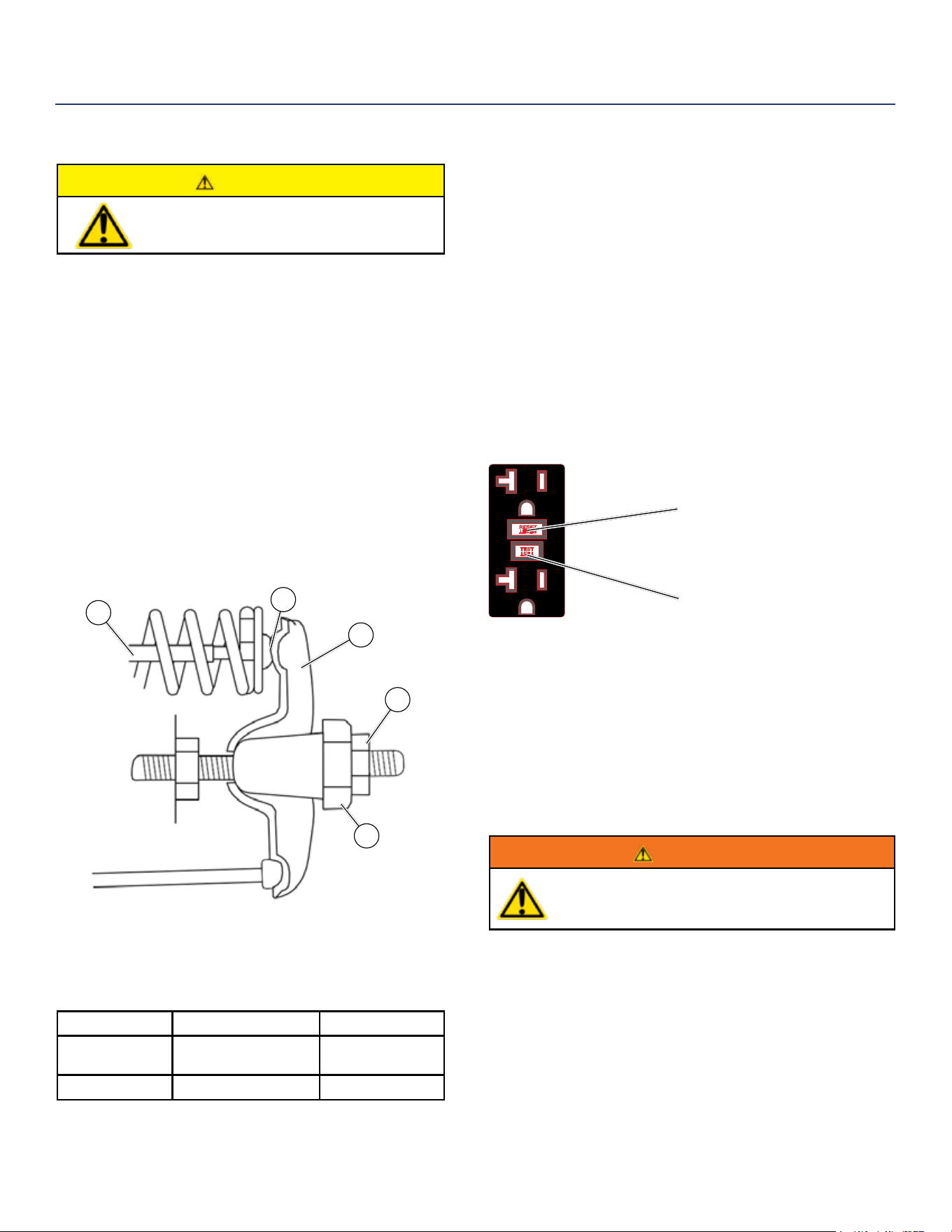
TESTING GFCI OUTLETS
1. Start the generator and allow it to warm up.
2. Press the test button on the GFCI outlet.
Test Button
Reset Button
3. The reset button should pop out and there will be
no power from the outlets. If the reset button does
not pop out, the GFCI outlet is not working correctly
and must be repaired before the generator can be
operated.
4. Press the reset button to restore power to the outlet.
BATTERY SERVICE
WARNING
Do not charge for over 8 hours. Leaving
the battery on the charger indenitely could
overcharge the battery and lead to battery failure.
To ensure the battery remains charged, the generator
should be started every 2 to 3 months and run for a
minimum of 15 minutes or a charger should be connected
to the battery and charged overnight. If using a battery
charger be sure to follow instructions provided by the
manufacturer for proper use.
CHECKING AND ADJUSTING VALVE LASH
CAUTION
Checking and adjusting valve lash
must be done when the engine is cold.
1. Remove the rocker arm cover and carefully remove
the gasket. If the gasket is torn or damaged, it must
be replaced.
2. Remove the spark plug so the engine can be rotated
more easily.
3. Rotate the engine to top dead center (TDC) of the
compression stroke. Looking through the spark plug
hole, the piston should be at the top.
4. Both the rocker arms should be loose at TDC on the
compression stroke. If they are not, rotate the engine
360°.
5. Insert a feeler gauge between the rocker arm and the
push rod and check for clearance (see Figure 24). See
Table 3 for valve lash specications.
1
2
3
4
5
Figure 24
(1) Push Rod, (2) Feeler Gauge Area
(3) Rocker Arm, (4) Jam Nut, (5) Adjusting Nut
(Table 3) Standard Valve Lash
Intake Valve Exhaust Valve
Valve Lash
0.0035 ± 0.0043 in
(0.09 ± 0.11 mm)
0.0043 ± 0.0051 in
(0.11 ± 0.13 mm)
Bolt Torque
8-12N.m 8-12N.m
MAINTENANCE
28 | Westinghouse Portable Power
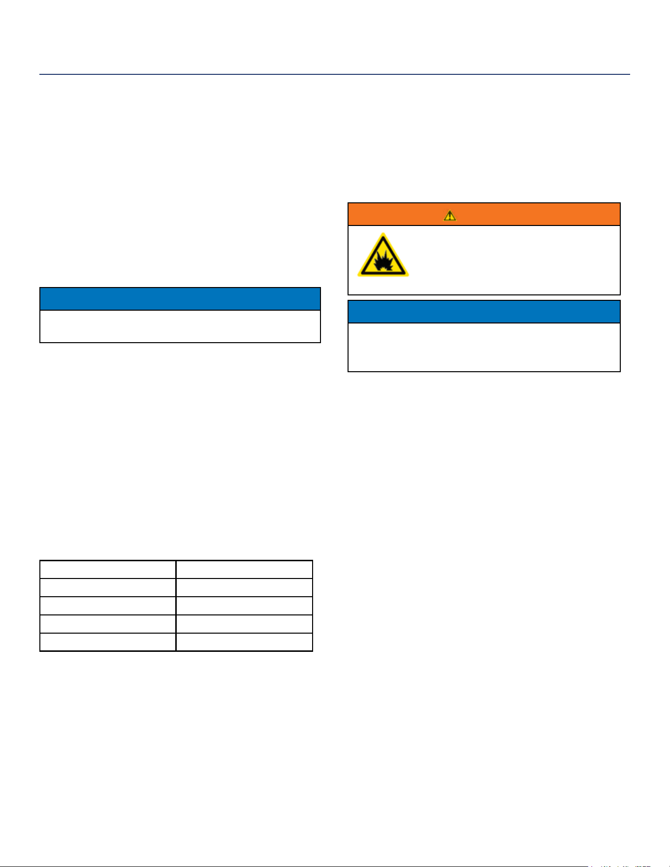
BATTERY REPLACEMENT
1. Remove the spark plug wire from spark plug.
2. Loosen and remove the bolt on the battery hold
down plate and swing the plate out.
3. Tip the battery forward slightly to access battery
cables.
4. Disconnect the black negative (-) battery cable from
the battery rst.
5. Disconnect the red positive (+) battery cable second
and remove the battery.
NOTICE
Dispose of the used battery properly according to the
guidelines established by your local or state government.
6. Install the new battery into the generator frame.
Battery must meet specications in table below to
work properly.
7. Connect the red positive (+) battery cable to the
battery rst.
8. Connect the black negative (-) battery cable to the
battery second.
9. Install the battery hold-down plate using the nuts
removed in step 2.
10. Install the spark plug wire onto spark plug.
See below for the battery specication
when replacing the battery.
Westinghouse Part No. 100557
After Market Battery Model YT9A
Volts 12
Amp Hr 9
Dimensions 5 5/16in by 3in by 5 3/8in
CLEANING THE GENERATOR
It is important to inspect and clean the generator after
every use.
Clean All Engine Air Inlet and Outlet Ports – Make sure
all engine air inlet and outlet ports are clean of any dirt
and debris to ensure the engine does not run hot.
Clean All Engine Cooling Fins – Use a damp rag and
a brush to loosen and remove all dirt on or around the
engine’s cooling ns.
Clean All Alternator Cooling Air Inlets and Exhaust
Ports – Make sure the cooling air inlets and exhaust
ports of the alternator are free of any debris and
obstructions. Use a vacuum cleaner to remove dirt and
debris stuck in the cooling air inlets and exhaust ports.
General Cleaning of the Generator – Use a damp rag to
clean all remaining surfaces.
STORING GENERATOR
WARNING
Never store a generator with fuel in the tank
indoors or in a poorly ventilated area where the
fumes can come in contact with an ignition source
such as a: 1) pilot light of a stove, water heater,
clothes dryer or any other gas appliance; or 2)
spark from an electric appliance.
NOTICE
Gasoline stored for as little as 60 days can go bad, causing gum,
varnish and corrosive buildup in fuel lines, fuel passages and the
engine. This corrosive buildup restricts the ow of fuel, preventing
an engine from starting after a prolonged storage period.
Proper care should be taken to prepare the generator for
any storage.
1. Make sure the Engine Switch is switched to STOP so
the generator does not draw power from battery.
2. Clean the generator as outlined in Cleaning the
Generator.
3. Drain all gasoline from the fuel tank as best as
possible.
4. With the fuel shut o valve open, start the engine
and allow the generator to run until all the remaining
gasoline in the fuel lines and carburetor is consumed
and the engine shuts o.
5. Close the fuel shut o valve.
6. Drain the remaining gas in the carburetor oat bowl
outlined in Draining Carburetor Float Bowl on page 23.
7. Change the oil (see Changing Engine Oil on page 25).
8. Remove the spark plug (see Spark Plug Maintenance
on page 26) and place about 1 tablespoon of oil in the
spark plug opening. While placing a clean rag over
the spark plug opening, slowly pull there coil handle
to allow the engine to turn over several times. This
will distribute the oil and protect the cylinder wall from
corroding during storage.
9. Replace the spark plug (see Spark Plug Maintenance
on page 26).
10. Move the generator to a clean, dry place for storage.
MAINTENANCE

Westinghouse Portable Power | 29
WARNING
Before attempting to service or troubleshoot the generator, the owner or service technician must rst read the owner’s manual and
understand and follow all safety instructions. Failure to follow all instructions may result in conditions that can lead to voiding of the EPA
certication or product warranty, serious personal injury, property damage or even death.
TROUBLESHOOTING
PROBLEM POTENTIAL CAUSE SOLUTION
Engine is running, but no
electrical output
1. Circuit breakers are tripped. 1. Reset the circuit breakers and check for overload
condition.
2. The power cord’s plug connector is not fully
engaged in the generator’s outlet.
2. Verify plug connector is rmly engaged in the
generator’s outlet. If using the 240V outlet, make sure plug
connector is rotated 1/4 turn in the clockwise direction.
3. Faulty or defective power cord 3. Replace power cord.
4. Faulty or defective electrical appliance 4. Try connecting a known good appliance to verify the
generator is producing electrical power.
5. GFCI outlet is tripped 5. Press the reset button on the GFCI outlet.
6. If trying 1-5 above does not solve the
problem, the cause might be the generator has
a fault.
6. Take the generator to your nearest authorized service
dealer.
Engine will not start or
remain running while
trying to start.
1. Fuel shuto valve is in the OFF position. 1. Move the fuel shut o valve to the ON position.
2. Generator is out of gasoline. 2. Add gasoline to the generator.
3. Fuel ow is obstructed. 3. Inspect and clean fuel delivery passages.
4. Unit is over choked. 4. Move the choke lever halfway between the ON and OFF
positions.
5. Starting battery may have insucient charge 5. On electric start models only. Check battery output and
charge battery as necessary.
6. Dirty air lter 6. Check and clean the air lter.
7. Low oil level shut down switch is preventing
the unit from starting.
7. Check oil level and add oil if necessary.
8. Spark plug boot is not fully engaged with the
spark plug tip.
8. Firmly push down on the spark plug boot to ensure the
boot is fully engaged
9. Spark plug is faulty. 9. Remove and check the spark plug. Replace if faulty.
10. Dirty/plugged spark arrestor 10. Check and clean the spark arrestor.
11. Stale fuel 11. Drain fuel and replace with fresh fuel.
12. If trying 1-11 above does not solve the
problem, the cause might be the generator has
a fault.
12. Take the generator to your nearest authorized service
dealer.
Generator suddenly
stops running.
1. Generator is out of fuel. 1. Check fuel level. Add fuel if necessary.
2. The low oil shut down switch has stopped
the engine.
2. Check oil level and add oil if necessary.
3. Too much load 3. Restart the generator and reduce the load.
4. If trying 1-3 above does not solve the
problem,the cause might be a fault in the
generator.
4. Take the generator to your nearest authorized service
dealer.
Engine runs
erratic; does not hold a
steady RPM.
1. Choke was left in the ON position.
1. Move choke to the OFF position
2. Dirty air lter 2. Clean the air lter.
3. Applied loads maybe cycling on and o 3. As applied loads cycle, changes in engine speed may
occur; this is a normal condition.
4. If trying 1-3 above does not solve
the problem, the cause might be a
fault in the generator
4. Take the generator to your nearest authorized service
dealer.
30 | Westinghouse Portable Power
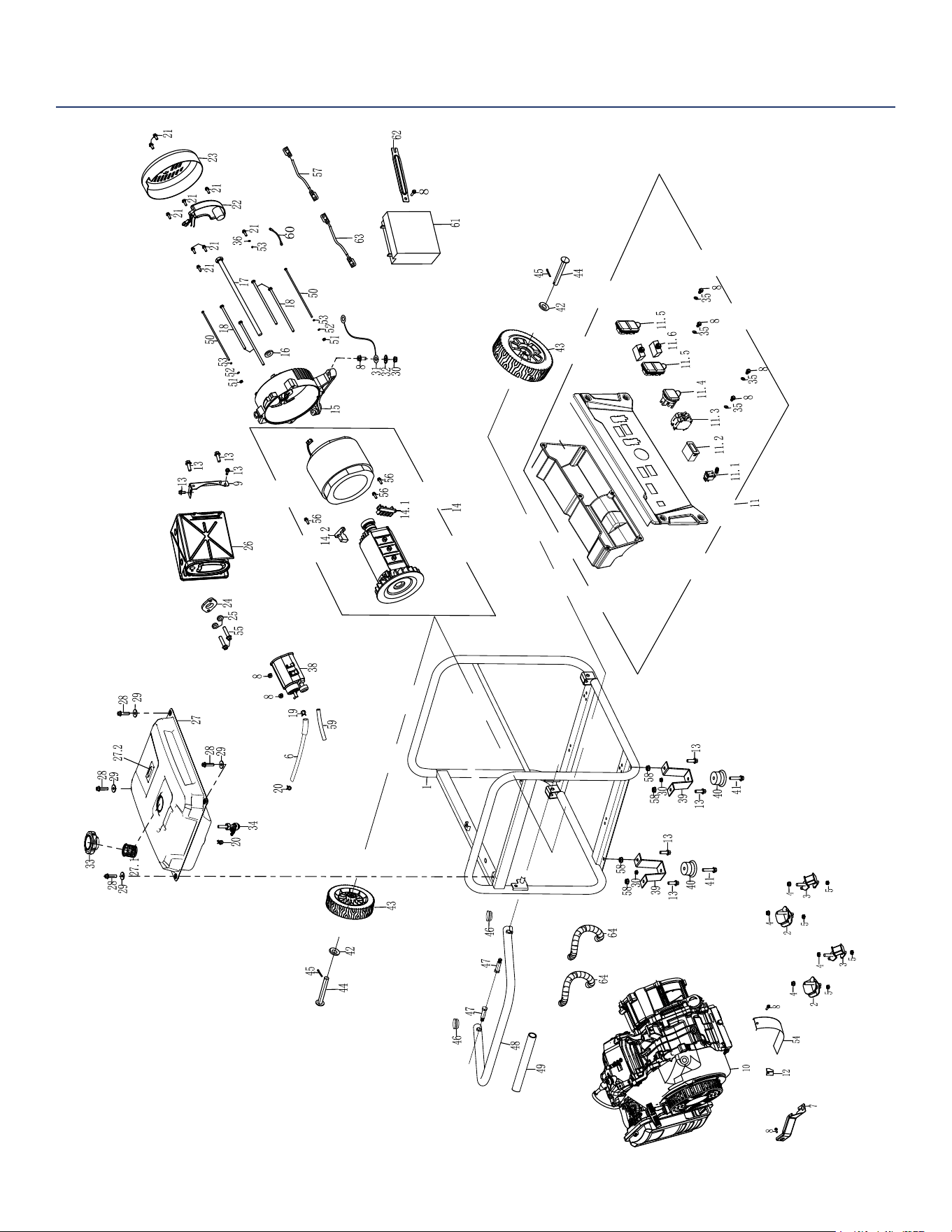
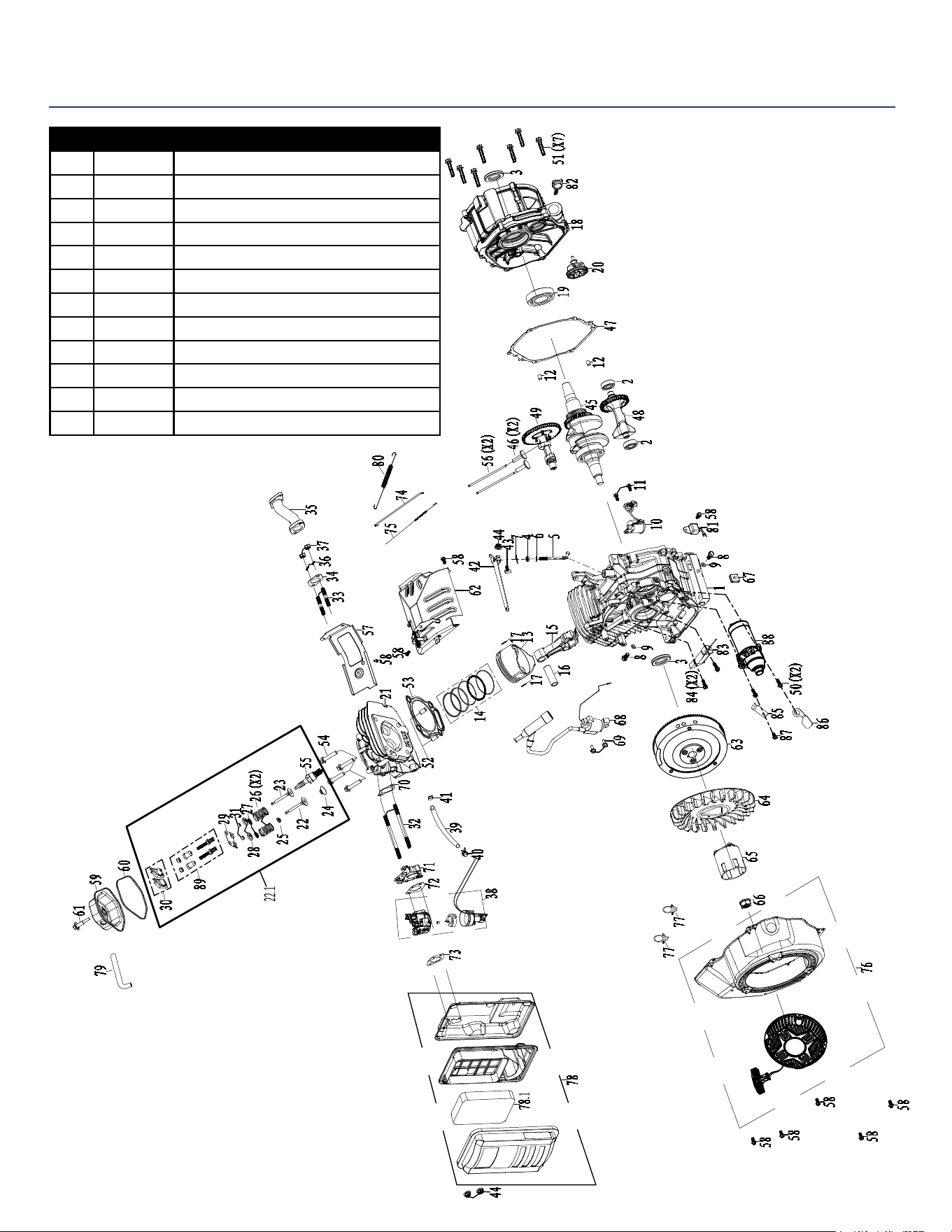
WGEN6000 EXPLODED VIEW

Westinghouse Portable Power | 31
WGEN6000 EXPLODED VIEW PART NO.
No. Part. Description
35 100547 WASHER
36 120508 TOOTH TYPE GASKET Φ5
38 150512 CARBON TANK
39 100512 SUPPORT, FRAME
40 100515 VIBRATION ISOLATION PAD,SQUARE
41 100518 BOLT M6X25
42 100510 FLAT WASHER Φ13XΦ37X4
43 100506 WHEEL
44 100504 AXLE
45 100508 COTTER PIN
46 100527 PLUG, HANDLE
47 100525 BOLT, HANDLE M10XΦ12.5X53.5
48 100521 HANDLE ASSEMBLY
49 100523 RUBBER, HANDLE
50 120535 BOLT M5X204
51 120510 NUT M5
52 120511 FLAT WASHER Ф5
53 120512 SPRING WASHER Ф5
54 180561 GUARD COVER, CRANKCASE
55 110503 BOLT M8X30
56 110518 BOLT M5X16
57 100555 NEGATIVE LEAD
58 100520 NUT M8
59 150510 CONNECTING PIPE
60 120516 GROUNDING WIRE
61 100557 BATTERY
62 100558 SHROUD, BATTERY
63 100584 POSITIVE LEAD
64 100591 TUBE, GLASS FIBER
- 230523 1.1L OIL BOTTLE
No. Part. Description
1 100601 FRAME
2-3 100552 ISOLATOR
4 100551 NUT M10
5 180524 NUT M8
6 150507 CARB CANISTER CONNECTING PIPE
7 180563 BRACKET, AIR CLEANER
8 120505 BOLT M6X12
9 110504 MUFFLER BRACKET
10 180591 ENGINE ASSY
11 130556 PANEL COMP
11.1 130534 SWITCH ASSEMBLY
11.2 130503 MULTIFUNCTION METER
11.3 130557 MAIN BREAKER
11.4 130505 L14-30R OUTLET
11.5 130506 GFCI RECEPTACLE
11.6 130533 CIRCUIT BREAKER 20A
12 180562 DUSTPROOF SHEET
13 100516 BOLT M8X16
14 120520 ROTOR/STATOR ASSY ALTERNATOR
14.1 120503 GROUNDING POST COMP
14.2 120502 CARBON BRUSH COMP
15 120504 REAR BEARING CARRIER
16 100540 GASKET, ROTOR BOLT Φ10.5×Φ30×4
17 120522 BOLT M10X1.25X255
18 120521 BOLT M6X165
19 150508 CLIP, FUEL LINE Φ9X0.8
20 140539 CLIP, FUEL LINE Φ10
21 120537 BOLT M5X12
22 120547 AUTOMATIC VOLTAGE REGULATOR (AVR)
23 120519 END COVER, GENERATOR
24 110501 EXHAUST PIPE GASKET
25 110502 SPRING WASHER Ф8
26 110517 MUFFLER COMP
27 150555 FUEL TANK ASSEMBLY
27.1 150506 FUEL FILTER
27.2 230514 FUEL GAGE
28 120536 BOLT M6X25
29 150501 WASHER FUEL TANK
30 120506 NUT M6
31 120528 FRAME WIRE
32 120508 BEARING Φ8
33 150505 FUEL TANK CAP COMP
34 150502 FUEL COCK
Westinghouse Generator Accessories (call to order)
210004 GENERATOR COVER
210003 WGC25 25’ POWER CORD
210052 30A 6 BREAKER TRANSFER SWITCH KIT - MODEL
WHMTS30
210075 25’ CORD 30AMP TRANSFER SWITCH
210076 50A 6 BREAKER TRANSFER SWITCH KIT - MODEL
WHMTS50
210051 25’ CORD 50AMP TRANSFER SWITCH
140545 HIGH ALTITUDE CARBURETOR KIT
m07500 MAINTENANCE KIT - SPARK ARRESTOR, SPARK
PLUG, AIR FILTERS
32 | Westinghouse Portable Power
WGEN6000 ENGINE VIEW
No. Part. Description
1 190223 CRANKCASE
2 180593 BALL BEARING
3 180504 OIL SEAL
4 190411 SEAL, GOVERNOR ARM SHAFT
5 190410 SHAFT, GOVERNOR ARM
6 190409 WASHER, GOVERNOR ARM SHAFT
7 190408 PIN, LOCK
8 180507 BOLT DRAIN PLUG
9 180508 WASHER, DRAIN PLUG
10 180586 OIL LEVEL SENSOR
11 130536 BOLT M6X16
12 180604 DOWEL PIN, CASECOVER

Westinghouse Portable Power | 33
No. Part. Description
13 190407 PISTON
14 190406 SCRAPER RING SET, PISTON
15 190405 ROD ASSEMBLY., CONNECTING
16 190404 PIN, PISTON
17 180791 CLIP, PISTON
18 180512 COVER ASSEMBLY, CRANKCASE
19 180530 BALL BEARING
20 190225 GOVERNOR ASSEMBLY
21 180514 CYLINDER HEAD
22 180743 VALVE, IN
22.1 190417 CYLINDER HEAD ASSEMBLY KIT
23 180780 VALVE EXHAUST
24 180752 RETURNER, INTAKE VALVE
25 180753 OIL SEAL,VALVE
26 190224 SPRING,VALVE
27 180744 LOCKING FLAPS
28 180755 SEAT, VALVE SPRING,EX
29 180798 PLATE, PUSH ROD GUIDE
30 180799 ROCKER ASSY
31 180756 ROTATOR
32 140503 BOLT, STUD
33 180571 BOLT, STUD
34 180522 EXHAUST GASKET
35 180521 EXHAUST PIPE
36 110502 SPRING WASHER
37 180524 NUT M8
38 140551 CARBURETOR ASSEMBLY
39 140507 FUEL LINE
40 140508 FUEL LINE CLIP
41 140506 RUBBER WASHER
42 180515 GOVERNOR ARM
43 300075 BOLT, GOVERNOR ARM
44 120506 NUT M6
45 190403 CRANKSHAFT ASSEMBLY
46 190402 LIFTER, VALVE
47 180511 CASECOVER GASKET
48 190401 BALANCING SHAFT
49 190400 CAMSHAFT ASSEMBLY
50 180807 BOLT M8X35
51 180808 BOLT M8X40
52 180742 PIN DOWEL
53 180513 CYLINDER HEAD GASKET
54 180523 BOLT M10X80
55 180526 SPARK PLUG
WGEN6000 ENGINE VIEW PART NO.
No. Part. Description
56 180810 ROD,PUSH
57 180520 SHROUD
58 120505 BOLT M6X12
59 180527 CYLINDER HEAD COVER
60 180528 HEADCOVER GASKET
61 180529 LOCK BOLT
62 180519 SHROUD ASSY, UPPER
63 180503 FLYWHEEL ASSEMBLY
64 180502 FAN, RECOIL STARTER
65 180501 PULLEY, STARTER
66 180500 NUT
67 180510 GROUNDING GROMMET
68 180505 IGNITION COIL ASSY
69 100518 BOLT M6X25
70 140504 INTAKE GASKET
71 140502 CARBURETOR SPACER
72 140501 CARBURETOR GASKET
73 140537 AIR CLEANER GASKET
74 180516 GOVERNOR ROD
75 180517 THROTTLE RETURN SPRING
76 170500 RECOIL STARTER ASSEMBLY
77 170502 CLIP
78 160500 AIR CLEANER ASSEMBLY
78.1 160037 AIR FILTER ELEMENT
79 180533 TUBE, BREATHER
80 180518 SPRING, GOVERNOR
81 180509 AMPLIFIER
82 180531 DIPSTICK
83 180506 CHARGE COIL
84 100636 BOLT M6X30
85 170506 CLAMPER CORD A
86 170504 CLAMPER CORD B
87 180589 BOLT M6X8
88 170503 STARTING MOTOR ASSEMBLY
34 | Westinghouse Portable Power
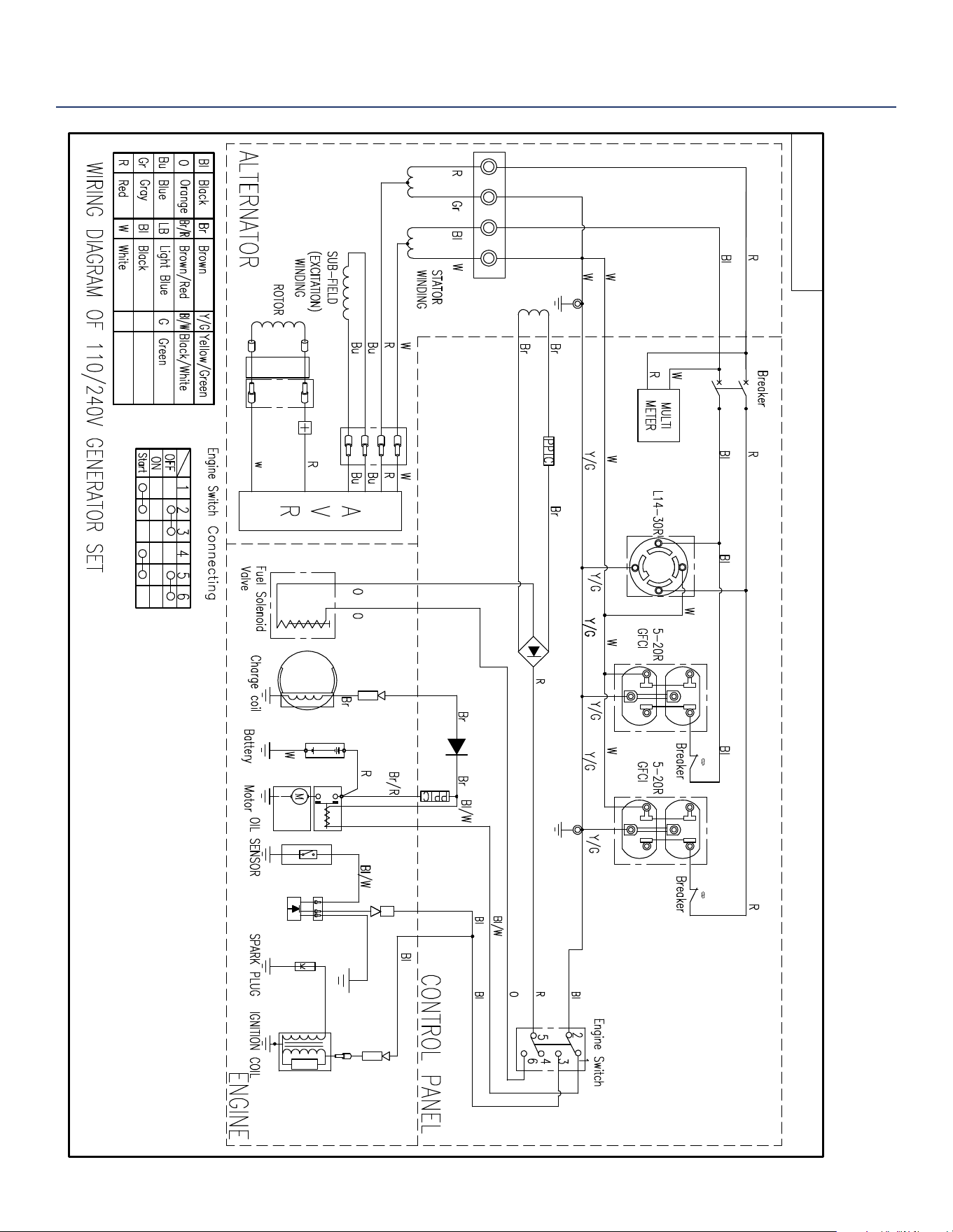
WGEN6000 SCHEMATIC
WH7500v SCHEMATIC

Westinghouse Portable Power | 35
Gasoline Running Watts 6000
Gasoline Peak Watts 7500
Running Amps
50A @ 240V
25A @ 120V
Peak Amps
31.25 @ 240V
62.5A @ 120V
AC Voltage 120/240 Volts
AC Frequency 60 Hz
Engine Horse Power (HP) 13 HP
Total Harmonic Distortion (THD) <23%
Automatic Voltage Regulator (AVR) Yes
Starting System Electric, Recoil
Battery Yes
Push Button Start No
Mobile App Compatible No
Engine Displacement 420cc
Engine Brand Westinghouse
Engine Type OHV 4 Stroke
Engine RPM 3600
Operational Volume (dBA) As low as 72 dBA
Spark Plug (included) Torch F7TC
Carburetor Kit Required to Operate
at Altitude
Yes
Altitude Carburetor Kit Number (sold
separate)
140545
Auto Idle Control No
Built-in Inverter No
Engine Lubrication Splash
Recommended Oil SAE 10W30
Oil Bottle Size (included) 1.1 qt. (37.2 oz.)
Oil Capacity (Quarts/Ounces) 1.1 qt. (37.2 oz.)
Low Oil Shutdown Automatic
Fuel Type
Unleaded Gasoline,
%10 Ethanol or less
Fuel Shut O Manual
Fuel Tank Material Steel
Fuel Tank Capacity (Gallons/Liters) 6.6 gal. (25 L)
Gasoline Fuel Gauge Yes
Choke type Manual
Choke Location Above Air Filter
AC Outlets
(1) 120/240V 30A
(L14-30R),
(2) Duplex 120V 20A
(5-20R)
DC Outlets (2) 5V USB ports
Ground Neutral Bonded
Covered Outlets Yes
Transfer Switch Ready Yes
Westinghouse Portable Transfer
Switch Ready (ST Switch)
No
GFCI Outlets Yes
VFT Data Center (volts, frequency,
lifetime hours)
Yes
RV Ready Outlet No
Overload Protection (circuit breaker) Yes
Handle Style
Single Handle with
Foam Grip
Wheel Kit Included Yes
Wheel Size
10 in. Diameter,
2.5 in. Wide
Wheel Type Polyurethane
Frame Thickness in. (mm) 1.25 in. (32 mm)
Emissions EPA, CARB
Canada CSA Compliant No
Muer Pulse-Flo™
Spark Arrestor Yes
Residential Warranty 3 Years
Commercial Warranty 1 Year
UPC 855464003483
GTIN 00855464003483
WGen6000
Generator Specifications

36 | Westinghouse Portable Power
Version 08.10.18KD