USER MANUAL
DO NOT RETURN THIS PRODUCT TO THE STORE
If you have questions or need assistance, please call customer
service at 855-944-3571.
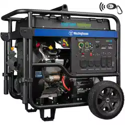
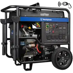
WGen5300
Portable Generator
Gasoline: 5300 Running Watts | 6600 Peak Watts
2 | Westinghouse Outdoor Power Equipment, LLC
INTRODUCTION
INTRODUCTION
WARNING: Operating, servicing, and maintaining
this equipment can expose you to chemicals including
engine exhaust, carbon monoxide, phthalates, and lead,
which are known to the State of California to cause
cancer and birth defects or other reproductive harm. To
minimize exposure, avoid breathing exhaust, and wear
gloves or wash your hands frequently when servicing
this equipment. For more information go to www.
P65warnings.ca.gov.
DISCLAIMERS
All information, illustrations, and specications in
this manual were in effect at the time of publishing.
The illustrations used in this manual are intended as
representative reference views only. We reserve the right
to make any specication or design change without notice.
ALL RIGHTS RESERVED
All rights reserved. No reproduction allowed in any form
without written permission from Westinghouse Outdoor
Power Equipment, LLC.
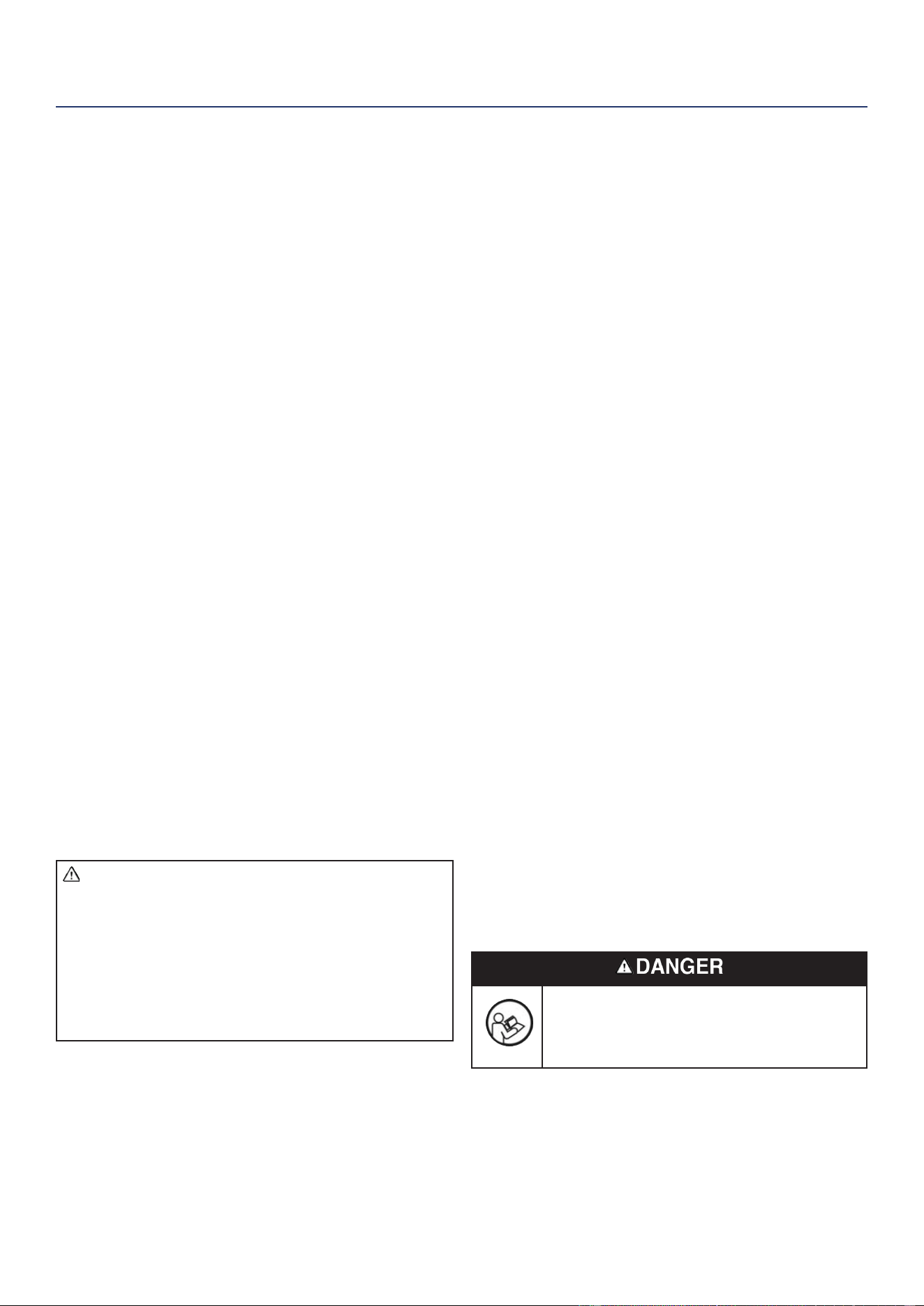
Read this manual before using or performing
maintenance on this product. Failure to follow
the instructions and safety precautions in this
manual can result in serious injury or death.
SAVE THESE INSTRUCTIONS
TABLE OF CONTENTS
IINTRODUCTION
DISCLAIMERS .........................................................................2
ALL RIGHTS RESERVED
........................................................2
SPECIFICATIONS
....................................................................3
SAFETY
SAFETY DEFINITIONS............................................................4
SAFETY SYMBOLS
.................................................................4
SAFETY INSTRUCTIONS
.......................................................5
SAFETY LABELS
.................................................................... 7
COMPONENTS
CONTROL PANEL COMPONENTS .........................................8
GENERATOR COMPONENTS
................................................9
ASSEMBLY
CARTON CONTENTS ...........................................................10
INSTALL FEET AND WHEELS
..............................................10
INITIAL OIL FILL
....................................................................11
FUEL
......................................................................................11
CONNECT THE BATTERY
....................................................12
OPERATION
GENERATOR LOCATION ......................................................13
GROUNDING
.........................................................................13
REMOTE START
...................................................................14
VOLTAGE SELECTOR SWITCH
...........................................14
BREAK-IN PERIOD
...............................................................14
BEFORE STARTING THE GENERATOR
..............................14
STARTING THE ENGINE
......................................................14
STOPPING THE ENGINE
...................................................... 15
FREQUENCY OF USE
..........................................................15
AC CIRCUIT BREAKERS
......................................................15
GENERATOR CAPACITY
......................................................15
POWER MANAGEMENT
.......................................................16
EXTENSION CORDS
............................................................16
TRANSPORTING
................................................................... 17
MAINTENANCE
MAINTENANCE SCHEDULE ................................................18
MAINTENANCE REMINDERS
..............................................18
MAINTENANCE REPLACEMENT PARTS
............................18
AIR FILTER MAINTENANCE
.................................................18
ENGINE OIL LEVEL CHECK
.................................................19
ENGINE OIL CHANGE
..........................................................19
SPARK PLUG MAINTENANCE
.............................................20
SPARK ARRESTOR SERVICE
.............................................. 20
BATTERY REPLACEMENT
...................................................20
STORAGE
.............................................................................. 21
FUEL VALVE MAINTENANCE
..............................................22
VALVE CLEARANCE
.............................................................22
TROUBLESHOOTING
TROUBLESHOOTING ...........................................................23
EXPLODED VIEWS AND PARTS LIST
ENGINE EXPLODED VIEW ................................................... 24
ENGINE PARTS LIST
............................................................25
GENERATOR EXPLODED VIEW
..........................................27
GENERATOR PARTS LIST
....................................................28
SCHEMATICS
SCHEMATICS ........................................................................29
ESPAÑOL .............................................................................30
FRANÇAIS ........................................................................... 54
INTRODUCTION

Westinghouse Outdoor Power Equipment, LLC | 3
INTRODUCTION
SPECIFICATIONS
Specications
Running Watts: 5300
Peak Watts: 6600
Rated Power @1.0 Power
Factor:
5.3 kW
Peak Power: 6.6 kVA
Rated Voltage: 120V/240V
Rated frequency: 60 Hz @ 3600 RPM
Phase: Single phase
Total Harmonic
Distortion:
≤ 23%
Engine Displacement: 274 cc
Starting Type: Recoil, electric start
Fuel Capacity: 4.7 Gallons (18 Liters)
Fuel Type:
Unleaded gasoline
87–93 octane*
Oil Capacity: 0.74 Quart (0.7 Liter)
Oil Type: SAE 10W-30
Spark Plug: 97108 (F7TC)
Spark Plug Gap:
0.024 – 0.032 in.
(0.60 – 0.80 mm)
Valve Intake
Clearance:
0.0031 – 0.0047 in.
(0.08 – 0.12 mm)
Valve Exhaust
Clearance:
0.0051 – 0.0067 in.
(0.13 – 0.17 mm)
AC Grounding System: Floating neutral
Voltage Regulator: AVR
Alternator Type: Brushed
Maximum Ambient
Temperature:
104°F (40°C)
Certications:
• EPA
• CARB
*Ethanol content of 10% or less. DO NOT use E15 or E85.
UPDATES
The latest User Manual for your Westinghouse
generator can be found under our support tab. https://
westinghouseoutdoorpower.com/pages/manuals
Or scan the following QR code with your smartphone
camera to be directed to the link.
NOTICE
This product is designed and rated for continuous
operation at ambient temperatures up to 104°F (40°C).
If needed, this product can be operated at temperatures
ranging from 5°F (15°C)–122°F (50°C) for short periods.
If the product is exposed to temperatures outside of this
range during storage, it should be brought back within
this range before operation. This product must ALWAYS
be operated outdoors in a well-ventilated area and far
away from doors, windows, and other vents.
Maximum wattage and current are subject to and
limited by such factors as fuel BTU content, ambient
temperature, altitude, engine conditions, etc. Maximum
power decreases about 3.5% for each 1,000 feet above
sea level, and will also decrease about 1% for each 10°F
(6°C) above 60°F (16°C) ambient temperature.
PRODUCT REGISTRATION
For trouble-free warranty coverage, it is important to
register your Westinghouse generator.
You can register by:
• Completing and mailing the product registration card
included in the carton.
• Registering your product online at:
https://westinghouseoutdoorpower.com/pages/
warranty-registration
• Scan the following QR code with your smartphone
camera to be directed to the mobile registration link.
• Sending the following product information to:
Westinghouse Outdoor Power
Warranty registration
777 Manor Park Drive
Columbus, OH 43228
For Your Records
Date of Purchase:
Model Number:
Serial Number:
Place of Purchase:
IMPORTANT: Keep your purchase receipt for trouble-free
warranty coverage.
4 | Westinghouse Outdoor Power Equipment, LLC
SAFETY
SAFETY
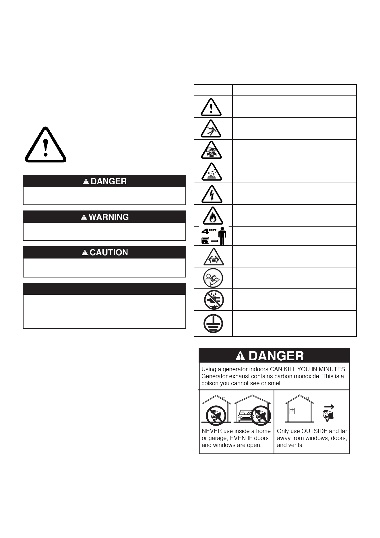
SAFETY DEFINITIONS
The words DANGER, WARNING, CAUTION, and
NOTICE are used throughout this manual to highlight
important information. Make sure that the meanings of this
safety information is known to all who operate, perform
maintenance on, or are near the generator.
This safety alert symbol appears
with most safety statements. It
means attention, become alert, your
safety is involved! Read and
abide by the message that follows
the safety alerts symbol.
Indicates a hazardous situation which, if not avoided,
will result in death or serious injury.
Indicates a hazardous situation which, if not avoided,
could result in death or serious injury.
Indicates a hazardous situation which, if not avoided,
could result in minor or moderate injury.
NOTICE
Indicates a situation which can cause damage
to the generator, personal property, and/or the
environment, or cause the equipment to operate
improperly.
Note: Indicates a procedure, practice or condition
that should be followed for the generator to function
in the manner intended.
SAFETY SYMBOLS
Follow all safety information contained in this manual
and on the generator.
Symbol Description
Safety Alert Symbol
Electrocution Hazard
Asphyxiation Hazard
Burn Hazard. DO NOT touch hot surfaces.
Electrical Shock Hazard
Fire Hazard
Maintain Safe Distance
Lifting Hazard
Read Manufacturer’s Instructions
DO NOT Operate in Wet Conditions
Ground. Consult with electrician to
determine grounding requirements before
operation.
Westinghouse Outdoor Power Equipment, LLC | 5
SAFETY
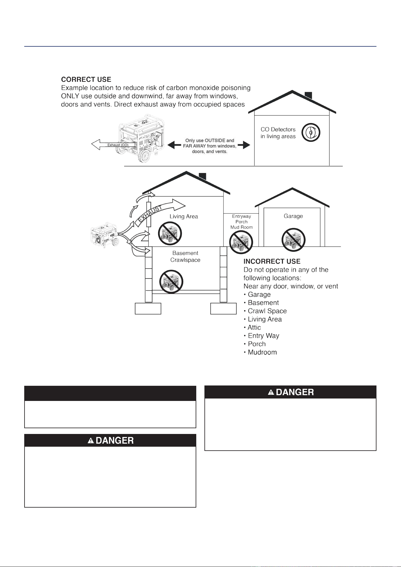
SAFETY INSTRUCTIONS
NOTICE
Install battery-powered carbon monoxide detectors or
plug-in carbon monoxide detectors with battery back-up
in living areas.
Fire and electrocution hazard. DO NOT connect to
a building’s electrical system unless the generator
and transfer switch have been properly installed and
the electrical output has been veried by a qualied
electrician. The connection must isolate the generator
power from utility power and must comply with all
applicable laws and electrical codes.
Electrocution hazard. NEVER use the generator in
a location that is wet or damp. NEVER expose the
generator to rain, snow, water spray, or standing water
while in use. Protect the generator from all hazardous
weather conditions. Moisture or ice can cause a short
circuit or other malfunction in the electrical circuit.

6 | Westinghouse Outdoor Power Equipment, LLC
SAFETY
GENERAL SAFETY PRECAUTIONS
• NEVER use the generator to power medical support
equipment.
• DO NOT operate the generator when you are tired or
under the inuence of drugs, alcohol, or medication.
• DO NOT use generator with electrical cords which are
worn, frayed, bare, or otherwise damaged.
• All electrical tools and appliances operated from this
generator must be properly grounded by use of a third
wire or be double-insulated.
• When this generator is used to supply a building wiring
system the generator must be installed by a qualied
electrician and connected to a transfer switch as a
separately derived system in accordance with NFPA 70,
National Electrical Code.
• If you begin to feel sick, dizzy, or weak while using
the generator, move to fresh air IMMEDIATELY. See a
doctor, as you can have carbon monoxide poisoning.
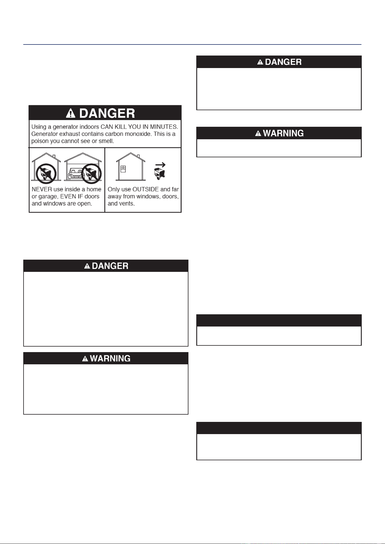
• Only use OUTSIDE and far away from windows, doors,
and vents as recommended by the US Department
of Health and Human Services Centers for Disease
Control and Prevention. Your specic home and/or wind
conditions may require additional distance.
• While operating and storing, keep at least ve feet
of clearance on all sides of the generator, including
overhead. Allow the generator to cool a minimum of 30
minutes before storage. Heat created by the mufer and
exhaust gases could be hot enough to cause serious
burns and/or ignite combustible objects.
• DO NOT touch the mufer or engine. They are very
HOT and will cause severe burns. DO NOT put body
parts or any ammable or combustible materials in the
direct path of the exhaust.
• ALWAYS remove any tools or other service equipment
used during maintenance away from the generator
before operating.
• Avoid skin contact with engine oil or gasoline. Wear
protective clothing and equipment. Wash all exposed
skin with soap and water.
• A transfer switch must be installed by a licensed
electrician approved by the authority having jurisdiction.
The installation must comply with all applicable laws
and electrical codes.
FUEL SAFETY
• Store fuel in a container approved for gasoline.
• DO NOT smoke when lling the generator with gasoline.
• DO NOT allow the generator’s gas tank to overow
when lling.
• Shut down the engine and allow it to cool for two
minutes before adding gasoline or oil to the generator.
• NEVER remove the fuel cap when the generator is
running. Shut off the engine and allow the unit to cool
at least two minutes. Remove the fuel cap slowly to
release pressure, keep fuel from escaping around the
cap, and to avoid the heat from the mufer igniting fuel
vapors. Tighten the fuel cap securely after refueling.
• Wipe spilled fuel from the unit.
• NEVER attempt to burn off spilled fuel.
• NEVER overll the fuel tank. Leave room for fuel to
expand. Overlling the fuel tank can result in a sudden
overow of gasoline and result in spilled gasoline
coming in contact with HOT surfaces.
• Spilled fuel can ignite. If fuel is spilled on the generator,
wipe up any spills immediately. Dispose of rag properly.
Allow area of spilled fuel to dry before operating the
generator.
• Wear eye protection while refueling.
• NEVER use gasoline as a cleaning agent.
• Store any containers containing gasoline or in a well-
ventilated area, away from any combustibles or source
of ignition.
GASOLINE AND GASOLINE VAPOR (GAS)
Fire and explosion hazard. Gasoline and is highly
explosive and ammable and can cause severe burns
or death.
• In case of a gas re, DO NOT attempt to extinguish
the ame if the fuel tank valve is in the ON position.
Introducing an extinguisher to a generator with an open
fuel valve could create an explosion hazard.
• Gas has a distinctive odor; this will help detect potential
leaks quickly.
• Gas vapors can cause a re if ignited.
• Gasoline is a skin irritant and needs to be cleaned up
immediately if it comes in contact with the skin.
• Flammable gas under pressure can cause a re or
explosion if ignited.
When starting the generator:
• Make sure that the fuel cap, air lter, spark plug, fuel
lines, and exhaust system are properly in place.
• If you spill any gasoline on the tank, allow it to fully
evaporate before operating.
• Make sure the generator is on a at surface before
operating.
• When transporting or servicing the generator:
• Disconnect the spark boot to prevent accidental starting.
When storing the generator:
• Store away from sparks, open ames, pilot lights, heat,
and other sources of ignition.

Westinghouse Outdoor Power Equipment, LLC | 7
SAFETY LABELS
SAFETY
8 | Westinghouse Outdoor Power Equipment, LLC
COMPONENTS
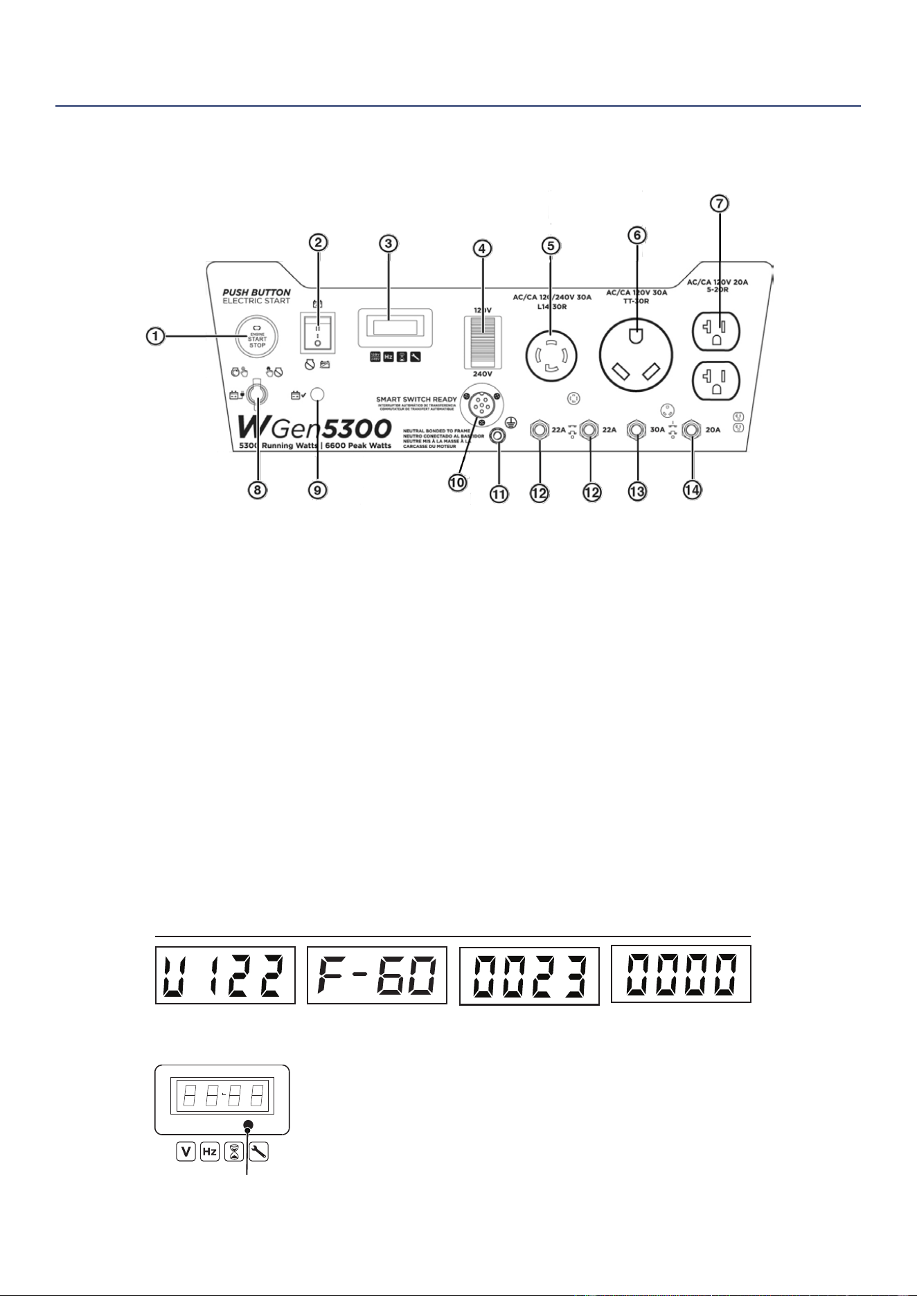
CONTROL PANEL COMPONENTS
COMPONENTS
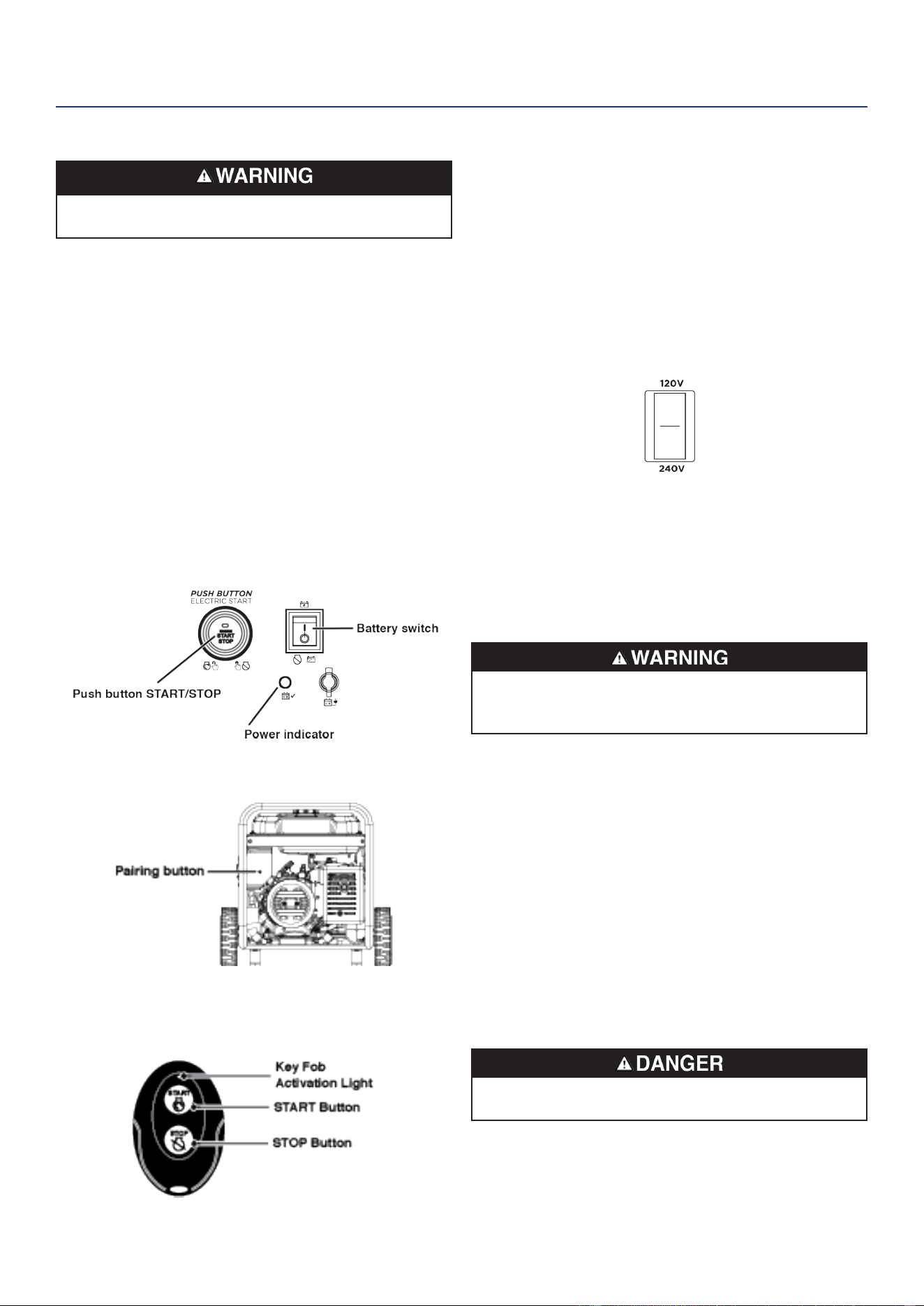
1. Push-Button START/STOP: Push once to
automatically start the engine. Push again to stop
the engine.
2. Battery Switch: Turns battery ON and OFF. Must be
ON before electric or remote start.
3. Data Center: Toggle to show voltage, frequency,
total hour meter, and run/maintenance timer.
4. Voltage Selector Switch: Select 120 Volts or 240
Volts. Shut the generator OFF before switching
voltages.
5. 120/240 Volt AC, 30 Amp NEMA L14-30R Twist-
Lock Receptacle: Receptacle can supply a
maximum of 30 Amps
6. 120 Volt AC, 30 Amp NEMA TT-30R Receptacle:
Receptacle can supply a maximum of 30 Amps.
7. 120 Volt AC, 20 Amp Duplex NEMA 5-20R
Receptacles: Receptacles can supply a maximum
of 20 Amps.
8. Battery Charging Port: Used to charge the battery
with the included battery charger.
9. Battery Indicator: Indicates that power is ON. Light
will remain illuminated while the unit is ON.
10. Smart Switch Outlet: Connects the Westinghouse
ST Switch (sold separately) to the control panel.
11. Ground Terminal: The ground terminal is used to
externally ground the generator.
12. 22-Amp Circuit Breakers: Each circuit breaker
limits the current that can be delivered through
each 120 Volt leg on L14-30R to 22 Amps.
13. 30-Amp AC Circuit Breaker: Circuit breaker limits
the current that can be delivered through the TT-
30R receptacle to 30 Amps.
14. 20-Amp AC Circuit Breaker: Circuit breaker limits
the current that can be delivered through the TT-
30R receptacle to 30 Amps.
DATA CENTER
Run Time/Maintenance:
Displays current run time.
Resets to zero when shut
down. Maintenance
reminder displayed
when required.
Frequency (Hz):
Displays power output
frequency in Hertz.
Voltage:
Displays current voltage
output.
Lifetime Hours:
Displays the lifetime run
hours.
Mode Button
METER V-F-T
Maintenance Codes:
P25: Change engine oil
P50: Clean air filter,
Change engine oil
P100: Change engine oil,
clean air filter, replace
fuel filter
Push the Mode button to cycle through
the data display modes.
Westinghouse Outdoor Power Equipment, LLC | 9
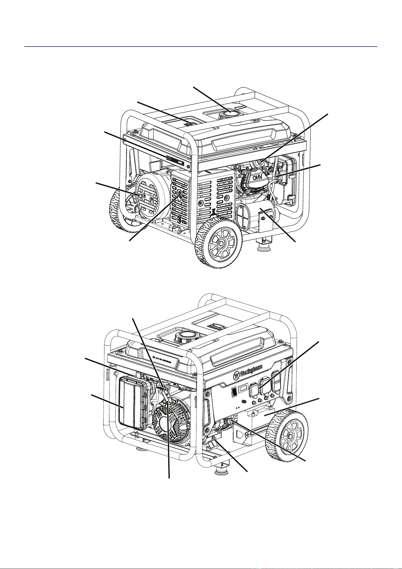
GENERATOR COMPONENTS
Oil drain
bolt
Oil dipstick/
filler neck
Fuel cap
Fuel gauge
Muffler/spark arrestor
Carbon canister
Carburetor
Alternator
cover
Control panel
Recoil
Starter
Air filter
Fuel tank
valve
Spark plug
Serial number
Choke lever
Battery
COMPONENTS
10 | Westinghouse Outdoor Power Equipment, LLC
ASSEMBLY
CARTON CONTENTS
Weight hazard. ALWAYS have assistance when lifting
the generator.
1. Carefully open the carton.
2. Remove and save the carton contents.
3. Remove and discard the packing tray.
4. Unfold the top of the plastic bag enclosing the generator.
5. Carefully cut the vertical corners of the carton to access
the generator.
6. Recycle or dispose of the packaging materials properly.
CARTON CONTENTS
• User manual
• Quick Start Guide
• Bottle of SAE 10W-30 oil
• Spark plug wrench
• Wrench
• Battery charger
• Oil Funnel
• Wheel and mounting foot components:
Item Quantity
• Mounting foot 2
• Flange bolt, M8 4
• Wheel 2
• Axle pin 2
• Washer 2
• Cotter pin 2
If any parts are missing, contact our service team at
[email protected] or call 1-855-944-3571.
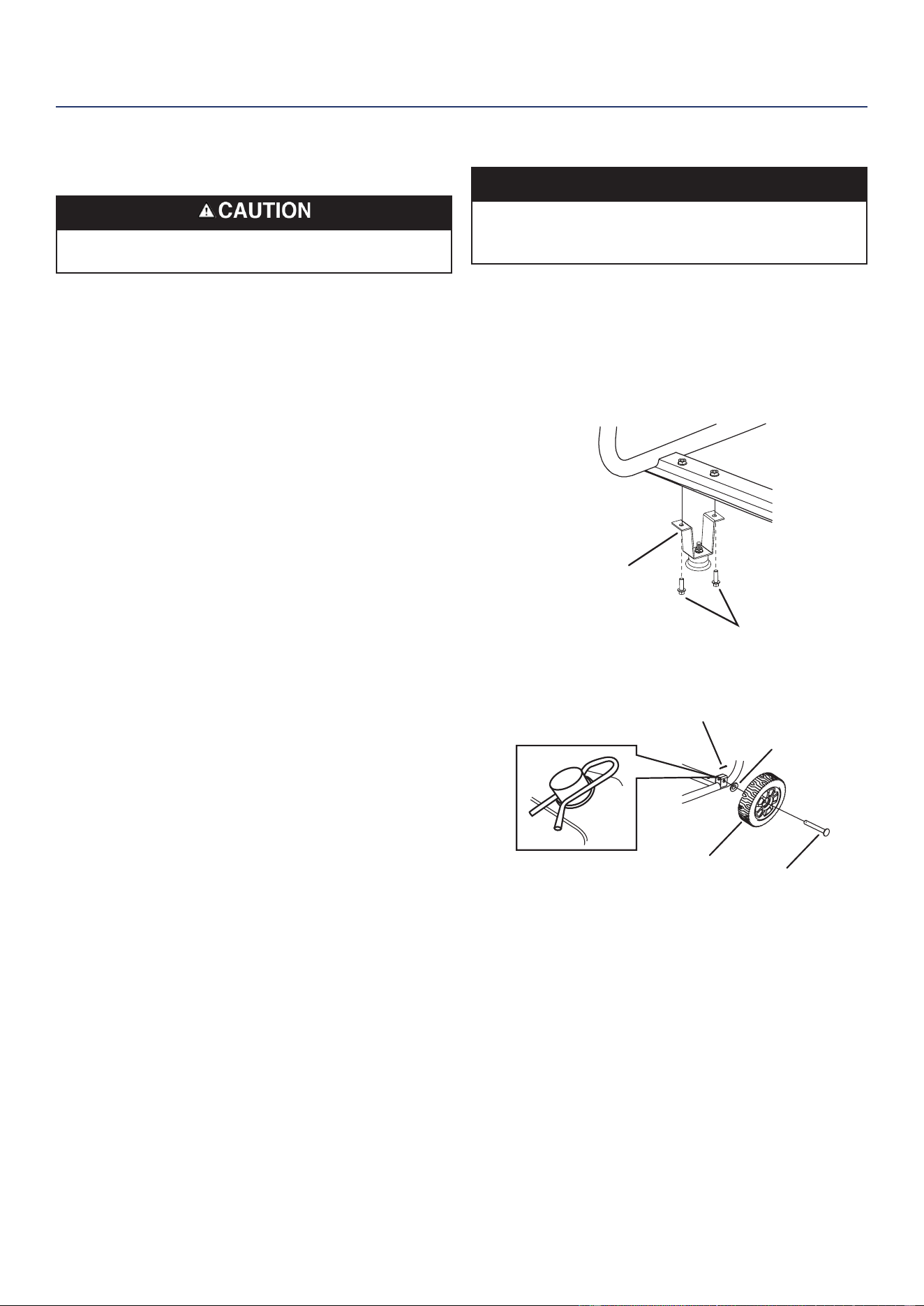
INSTALL FEET AND WHEELS
NOTICE
Assembling the generator will require lifting the unit on
one side. Install the mounting feet and wheel before
adding fuel or oil.
1. Place generator on a at surface.
2. Tip the generator on a piece of cardboard or other soft
material to protect the frame paint and prevent the
generator from sliding.
3. With the included wrench, install the mounting feet to
the frame as shown.
Mounting foot
Bolt, M8
4. Install the wheels as shown.
Axle pin
Wheel
Cotter pin
Washer
Note: The wheels are only intended for hand transport.
The wheels are not suitable for towing the generator
either on or off-road.
ASSEMBLY
Westinghouse Outdoor Power Equipment, LLC | 11
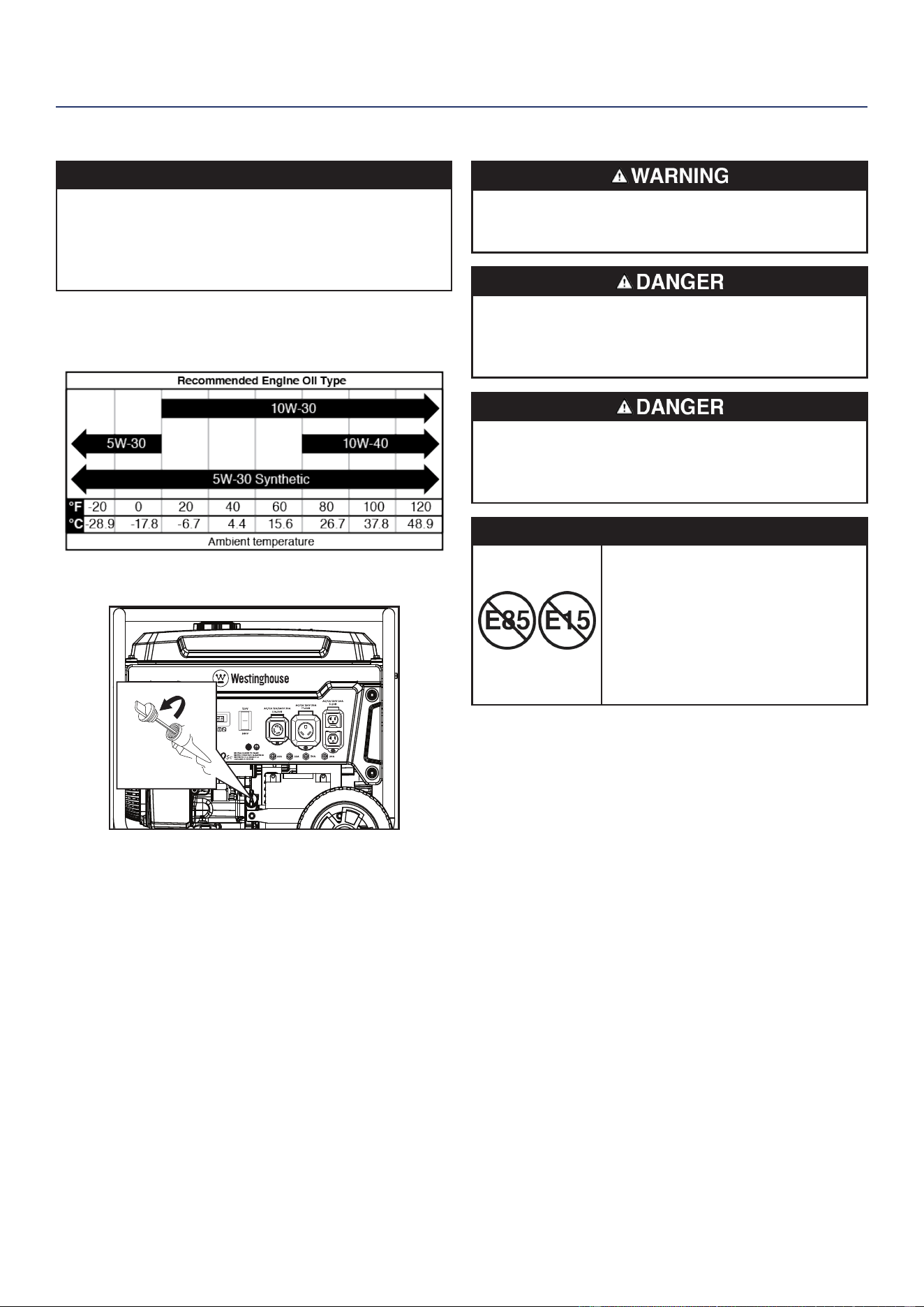
INITIAL OIL FILL
NOTICE
THIS GENERATOR HAS BEEN SHIPPED WITHOUT
OIL. DO NOT attempt to crank or start engine before
it has been properly serviced with recommended oil.
Failure to add engine oil before starting will result in
serious engine damage.
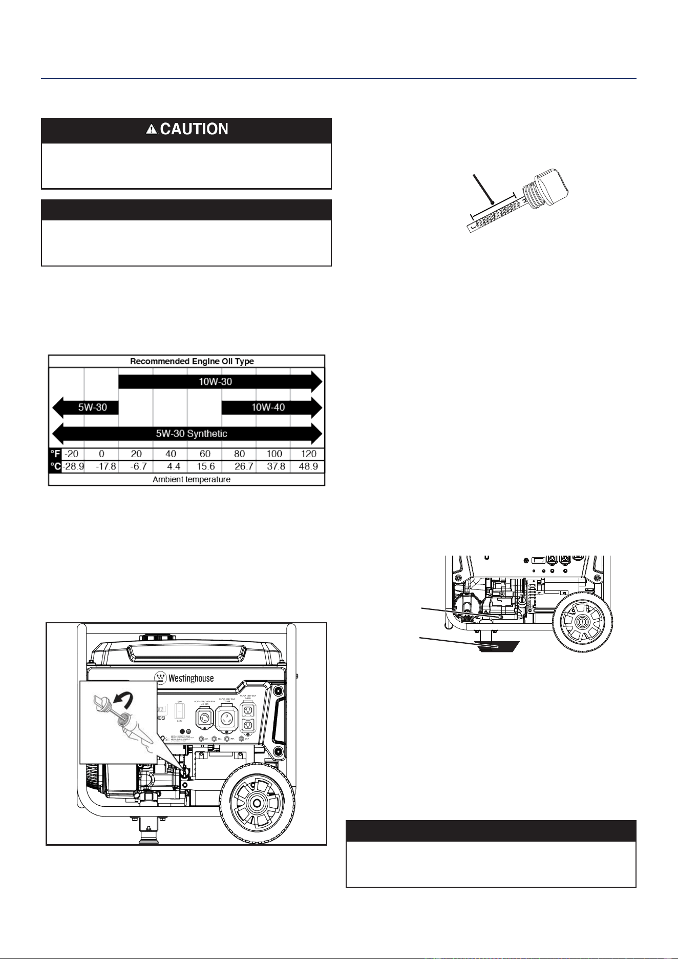
The included, recommended oil type for typical use is
10W-30 engine oil. If running the generator in extreme
temperatures, refer to the following chart.
1. On a level surface, remove the oil dipstick.
2. Using the supplied funnel and oil, add oil into oil ller
neck.
Note: As residual oil from the factory may remain in the
engine, add the oil incrementally near the end of the
bottle to prevent overlling the engine. See Engine
Oil Level Check in the Maintenance section.
3. Wipe the oil dipstick clean. Replace the oil dipstick and
hand-tighten.
FUEL
Fire and explosion hazard. NEVER use a gasoline
container, gasoline tank, or any other fuel item that is
broken, cut, torn or damaged.
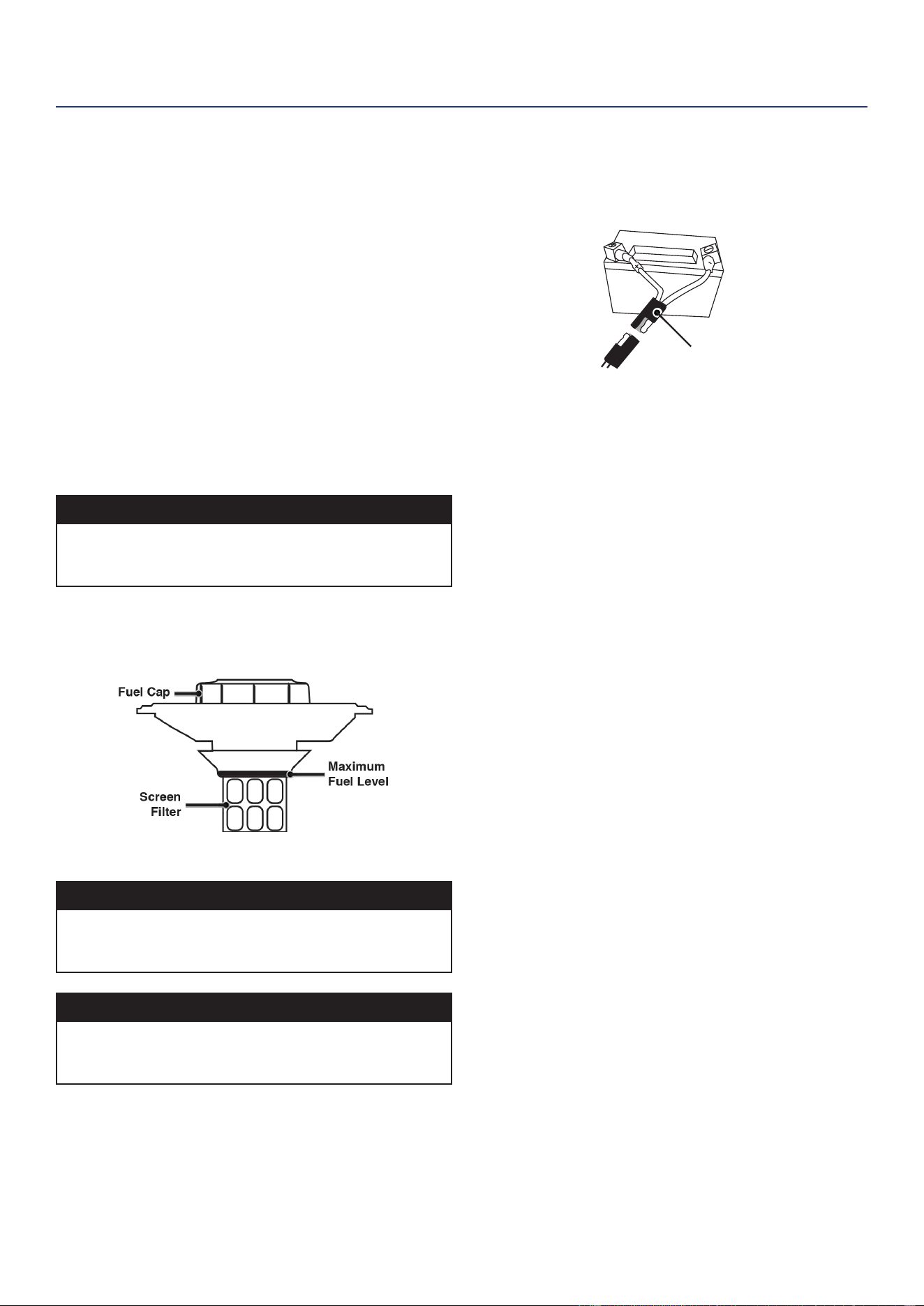
Fire and explosion hazard. DO NOT overll fuel tank. Fill
only to the red ll ring located in the in-tank fuel screen
lter. Overlling may cause fuel to spill onto engine
causing a re or explosion hazard.
Fire and explosion hazard. NEVER refuel the generator
while the engine is running. ALWAYS turn the engine off
and allow the generator to cool for two minutes before
refueling.
NOTICE
DO NOT use E15 or E85 fuel in
this product. Engine or equipment
damage caused by stale fuel or
the use of unapproved fuels (such
as E15 or E85 ethanol blends) is
not covered by warranty. Only use
unleaded gasoline containing up to
10% ethanol.
FUEL REQUIREMENTS
• CLEAN, FRESH, unleaded gasoline, 87–93 octane.
• Up to 10% ethanol (gasohol) is acceptable (where
available; non-ethanol fuel is recommended).
• DO NOT use E85 or E15.
• DO NOT use a gas oil mix.
• DO NOT modify the engine to run on alternate fuels.
• DO NOT fuel indoors.
• DO NOT create a spark or ame while fueling.
ASSEMBLY
12 | Westinghouse Outdoor Power Equipment, LLC
USING FUEL STABILIZER
Adding a fuel stabilizer (not included) extends the usable
life of fuel and helps prevent deposits from forming that
can clog the fuel system. Follow the manufacturer’s
instructions for use.
ALWAYS mix the correct amount of fuel stabilizer to
gasoline in an approved gasoline container before fueling
the generator. Run the generator for ve minutes to allow
the stabilizer to treat the entire fuel system.
FILLING THE FUEL TANK
1. Turn the generator OFF and allow to cool for a minimum
of two minutes before fueling.
2. Place the generator on level ground in a well-ventilated
area.
3. Clean area around fuel cap and remove the cap slowly.
NOTICE
Only ll the tank from an approved gasoline container.
Make sure the gasoline container is internally clean and
in good condition to prevent fuel system contamination.
4. Slowly add the recommended fuel. DO NOT overll. Fill
only to the red maximum ll ring on the fuel screen lter
visible in the ller neck.
5. Install the fuel cap.
NOTICE
Fuel can damage paint and plastic. Use caution when
lling the fuel tank. Damage caused by spilled fuel is not
covered under warranty.
NOTICE
Clean the fuel screen lter of debris before and after
each fueling. Remove the fuel screen lter by slightly
compressing it while removing it from the fuel tank.
CONNECT THE BATTERY
A quick-connect battery plug is pre-installed on the battery.
Remove the cable tie securing the plugs then push rmly
to connect them.
Quick-Connect Plug
Note: The generator is equipped with a battery charging
feature. Once the engine is running, a small charge
will slowly recharge the battery.
ASSEMBLY
Westinghouse Outdoor Power Equipment, LLC | 13
OPERATION
GENERATOR LOCATION
Read and understand all safety information before starting
the generator.
NEVER operate the generator inside any building, including
garages, basements, crawlspaces, sheds, enclosure, or
compartment, including the generator compartment of a
recreational vehicle.
Electrocution hazard. NEVER use the generator in
a location that is wet or damp. NEVER expose the
generator to rain, snow, water spray, or standing water
while in use. Protect the generator from all hazardous
weather conditions. Moisture or ice can cause a short
circuit or other malfunction in the electrical circuit. Using
a generator or electrical appliance in wet conditions,
such as rain or snow, or near a pool or sprinkler system,
or when your hands are wet, could result in electrocution
Fire hazard. Only operate the generator on a solid, level
surface. Operating the generator on a surface with loose
material such as sand or grass clippings can cause debris
to be ingested by the generator that could block cooling
vents or the air intake system. Allow the generator to
cool for 30 minutes before transport or storage.
The generator should be on a at, level surface at all times
(Even while not in operation). The generator must have
at least 5 ft. (1.5 m) of clearance from all combustible
material.
DO NOT operate the generator in the back of a SUV,
camper, trailer, truck bed (regular, at, or otherwise), under
stairs, next to walls or buildings, or in any other location
that will not allow for adequate cooling of the generator
and/or the mufer. DO NOT contain generators during
operation.
Asphyxiation hazard. Place the generator in a well-
ventilated area. DO NOT place the generator near vents
or intakes where exhaust fumes could be drawn into
occupied or conned spaces. Carefully consider wind
and air currents when positioning the generator.
GROUNDING
Shock hazard. Failure to properly ground the generator
can result in electric shock.
The generator neutral is oating. The generator ground
terminal is connected to the frame of the generator, the
metal non-current-carrying parts of the generator, and
the ground terminals of each receptacle. The generator
(stator winding) is isolated from the frame and from the
AC receptacle ground pin. Electrical devices that require
a grounded receptacle pin connection may not function
properly.
If this generator will be used only with cord and plug
equipment connected to the receptacles mounted on the
generator, National Electric Code does not require that
the unit be grounded. However, other methods of using
the generator may require grounding to reduce the risk of
shock or electrocution.
Before using the ground terminal, consult a qualied
electrician, electrical inspector, or local agency having
jurisdiction for local codes or ordinances that apply to the
intended use of the generator.
NOTICE
Only use grounded 3-prong extension cords, tools, and
appliances, or double-insulated tools and appliances.
HIGH ALTITUDE OPERATION
Engine power is reduced the higher you operate above sea
level. Output will be reduced approximately 3.5% for every
1000 feet of increased altitude from sea level.
High altitude adjustment is required for operation at
altitudes over 2000 ft. (762 m). Operation without this
adjustment will cause decreased performance, increased
fuel consumption, and increased emissions.
NOTICE
DO NOT operate the generator at altitudes below 2,000
ft. (762 m) with the high altitude kit installed. Engine
damage may occur.
High Altitude Carburetor Kit: Part# 518965
OPERATION
14 | Westinghouse Outdoor Power Equipment, LLC
REMOTE START
Verify that the area around the generator is clear before
remote starting the generator.
The remote start key fob included with the generator should
be attached to the recoil handle or control panel. If your
unit was shipped without a key fob, contact Westinghouse
customer service.
The generator can be started remotely from up to 99 feet
(30 meter) using the remote start key fob.
Note: As the batteries in the remote start key fob drain,
operational distance will decrease.
PAIRING THE REMOTE START
Remote replacement batteries: (2) CR2016
If the remote start key fob is replaced or needs re-paired to
the generator, follow this procedure.
1. Turn the generator battery switch to the ON position.
The power indicator light will illuminate.
2. Push and hold the red Pairing button on the side of the
control panel until the START/STOP button illuminates.
3. Push and hold the STOP button on the key fob until the
START/STOP button illumination turns OFF. Release
the button. The START/STOP button will illuminate after
the button is released.
4. Push and hold the START button on the key fob until the
START/STOP button illumination turns OFF. Release
the button. The START/STOP button will illuminate after
the button is released.
5. Push the Pairing button on the side of the control panel
until the START/STOP button illumination turns OFF.
Release the button.
6. Turn the generator battery switch to the OFF position.
The remote is now paired.
VOLTAGE SELECTOR SWITCH
The 120V/240V selector switch gives the user the ability to
double the amperage in the generator for more demanding
applications. The voltage selector switches the dual 120V
AC windings of the generator to produce 120V or 240V.
If a 240V appliance is connected to the 4-prong L14-30R
receptacle, the switch must be in the “240V” position. The
120V only outlets will not output power when the Voltage
Selector is in the 240V position.
Only change the Voltage Selector Switch with the
generator OFF. DO NOT switch the voltage while the
generator is running or powering appliances.
BREAK-IN PERIOD
For proper break-in, DO NOT exceed 50% of the rated
running watts (2650 watts) during the rst ve hours of
operation.
Vary the load occasionally to allow stator windings to heat
and cool and help seat the piston rings.
BEFORE STARTING THE GENERATOR
Verify that:
• The generator is placed in a safe, appropriate location.
• The generator is on a dry, at, and level surface.
• The engine is lled with oil.
• All loads are disconnected.
Fire and explosion hazard. DO NOT move or tip the
generator during operation.
STARTING THE ENGINE
1. Verify that fuel is in the gas tank.
2. Turn the fuel tank valve to the ON position.
OPERATION
Westinghouse Outdoor Power Equipment, LLC | 15
3. Push the battery switch to the ON position.
4. Choose the starting method:
a. Remote Start: Push and hold the START button on
the remote start key fob for one second.
b. Push-Button Start: Push and hold the engine
START/STOP button for two seconds.
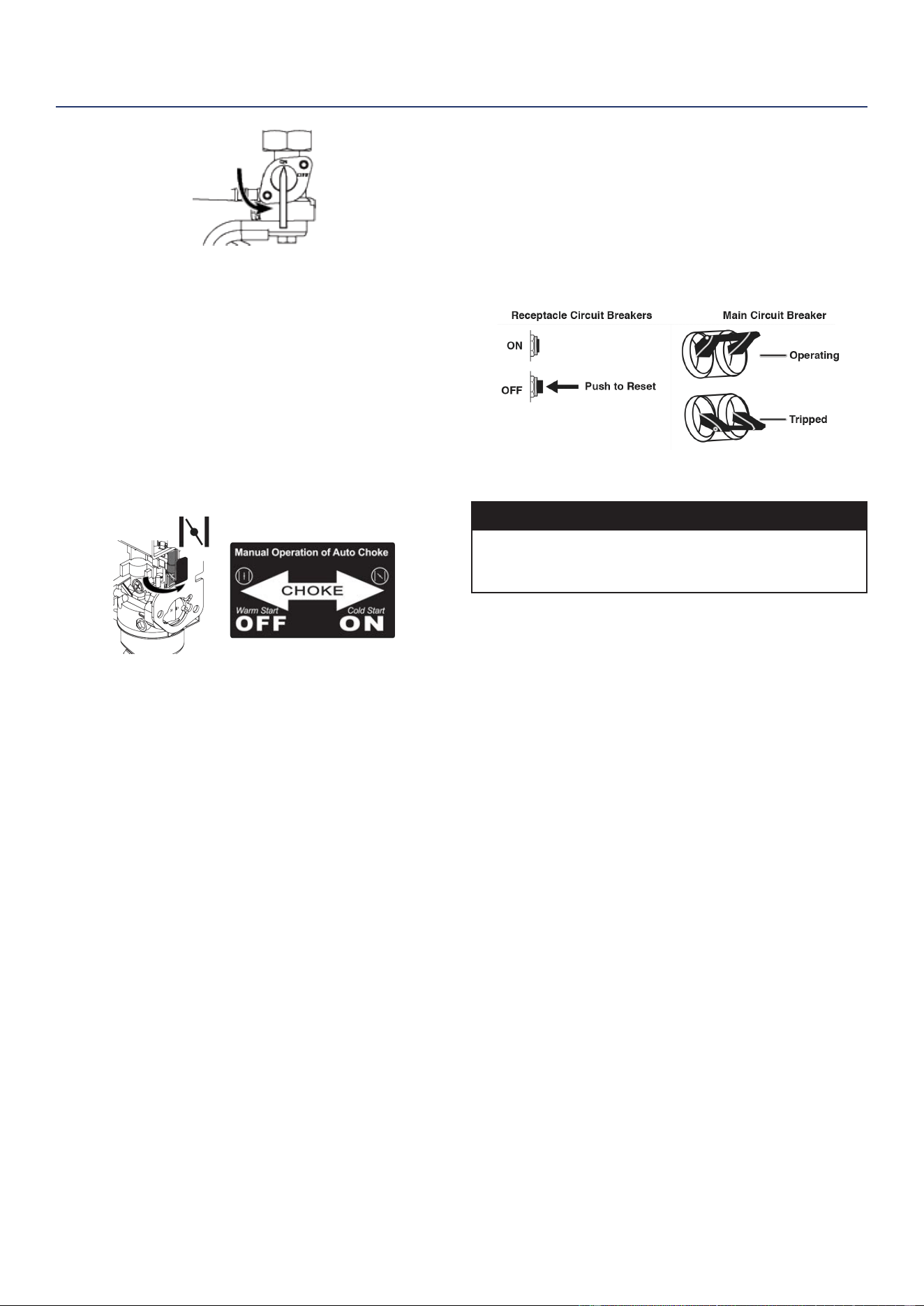
c. Recoil Start: Manually close the choke if the engine
is cold. Firmly grasp and pull the recoil handle slowly
until you feel increased resistance, then pull rapidly.
Note: During pushbutton or remote start the engine will
automatically set the choke and begin the start
sequence. If the engine fails to start, the generator
will attempt to start the engine two more times.
STOPPING THE ENGINE
1. Turn off and unplug all connected electrical loads.
IMPORTANT: NEVER start or stop the generator with
electrical devices connected.
2. Let the generator run with no load for several minutes to
stabilize internal temperatures of the engine.
3. Push and hold the START/STOP button for one second
or push STOP on the remote start key fob for one
second.
Note: Alternately, if the generator is used infrequently, turn
the fuel tank valve to the OFF position to limit the
residual fuel remaining in the carburetor oat bowl.
The engine will stop when fuel in the carburetor and
fuel line is exhausted.
FREQUENCY OF USE
If the generator will be used on an infrequent or intermittent
basis (more than one month before next use), refer to the
Storage section of this manual for information regarding
fuel deterioration.
AC CIRCUIT BREAKERS
The circuit breakers will automatically switch OFF if there
is a short circuit or a signicant overload of the generator
at each receptacle.
If an AC circuit breaker switches OFF automatically,
check that the appliance is working correctly and it does
not exceed the rated load capacity of the circuit before
resetting the AC circuit breaker ON.
GENERATOR CAPACITY
NOTICE
DO NOT overload the generator’s capacity. Exceeding
the generator’s wattage/amperage capacity can damage
the generator and/or electrical devices connected to it.
Make sure the generator can supply enough continuous
(running) and surge (starting) watts for the items you will
power at the same time.
The total power requirements (Volts x Amps = Watts) of all
appliances connected must be considered. Appliance and
power tool manufacturers usually list rating information
near the model or serial number.
To determine power requirements:
1. Select the items you will power at the same time.
2. Total the continuous (running) watts of these items. This
is the amount of power the generator must produce
to keep the items running. See the wattage reference
chart.
3. Estimate how many surge (starting) watts you will need.
Surge wattage is the short burst of power needed to
start electric motor-driven tools or appliances such as a
circular saw or refrigerator. Because not all motors start
at the same time, total surge watts can be estimated by
adding only the item(s) with the highest additional surge
watts to the total rated watts from step 2.
OPERATION
16 | Westinghouse Outdoor Power Equipment, LLC
Example:
Tool or Appliance
Running
Watts*
Starting
Watts*
RV Air Conditioner (11,000 BTU) 1010 1600
TV (at screen) 120 235
RV Refrigerator 180 600
Radio 200 0
Light (75 Watts) 300 0
Coffee Maker 600 0
Totals 2410 2435
Total Running Watts* 2410
Highest Starting Watts* + 1600
Total Starting Watts Needed 4010
*Wattages listed are approximate. Verify actual wattage.
POWER MANAGEMENT
To prolong the life of the generator and attached devices,
use care when adding electrical loads to the generator.
There should be nothing connected to the generator
outlets before starting the engine. The correct and safe
way to manage generator power is to sequentially add
loads as follows:
1. With nothing connected to the generator, start the
engine as described in this manual.
2. Plug in and turn on the rst load, preferably the largest
load you have.
3. Permit the generator output to stabilize (engine runs
smoothly and attached device operates properly).
4. Plug in and turn on the next load.
5. Again, permit the generator to stabilize.
6. Repeat steps 4 and 5 for each additional load.
Wattage Reference
Tool or Appliance
Est. Running
Watts*
Est. Starting
Watts*
Incandescent Lights
(4 Quantity x 75 Watts)
300 0
TV (at screen) 120 235
Sump Pump (1/3 hp) 800 1300
Refrigerator or Freezer 700 2200
Well Pump (1/3 hp) 1000 2000
Furnace (1/2 hp) 800 2350
Radio 200 0
Drill (3/8”, 4 amps) 440 600
Circular Saw
(Heavy Duty, 7-1/4”)
1400 2300
Miter Saw (10”) 1800 1800
Table Saw (10”) 2000 2000
*Wattages listed are approximate. Verify actual wattage.
EXTENSION CORDS
Asphyxiation hazard. Extension cords running directly
into the home increase the risk of carbon monoxide
poisoning through any openings. If an extension cord
running directly into your home is used to power indoor
items, there is a risk of carbon monoxide poisoning to
people inside the home. ALWAYS use battery-powered
carbon monoxide detector (s) that meet current UL 2034
safety standards when running the generator. Regularly
check the detector (s) battery.
Asphyxiation hazard. When operating the generator with
extension cords, make sure the generator is located in
an open, outdoor area, far away from occupied spaces
with exhaust pointed away.
Fire and electrocution hazard. NEVER use worn or
damaged extension cords. Damaged or overloaded
extension cords could overheat, arc, and burn resulting
in death or serious injury.
Before connecting an AC appliance or power cord to the
generator:
• Use grounded 3-prong extension cords, tools, and
appliances, or double-insulated tools and appliances.
• Make sure the tool or appliance is in good working
order. Faulty appliances or power cords can create a
potential for electric shock.
• Make sure the electrical rating of the tool or appliance
does not exceed the rated power of the generator or the
receptacle being used.
OPERATION
Westinghouse Outdoor Power Equipment, LLC | 17
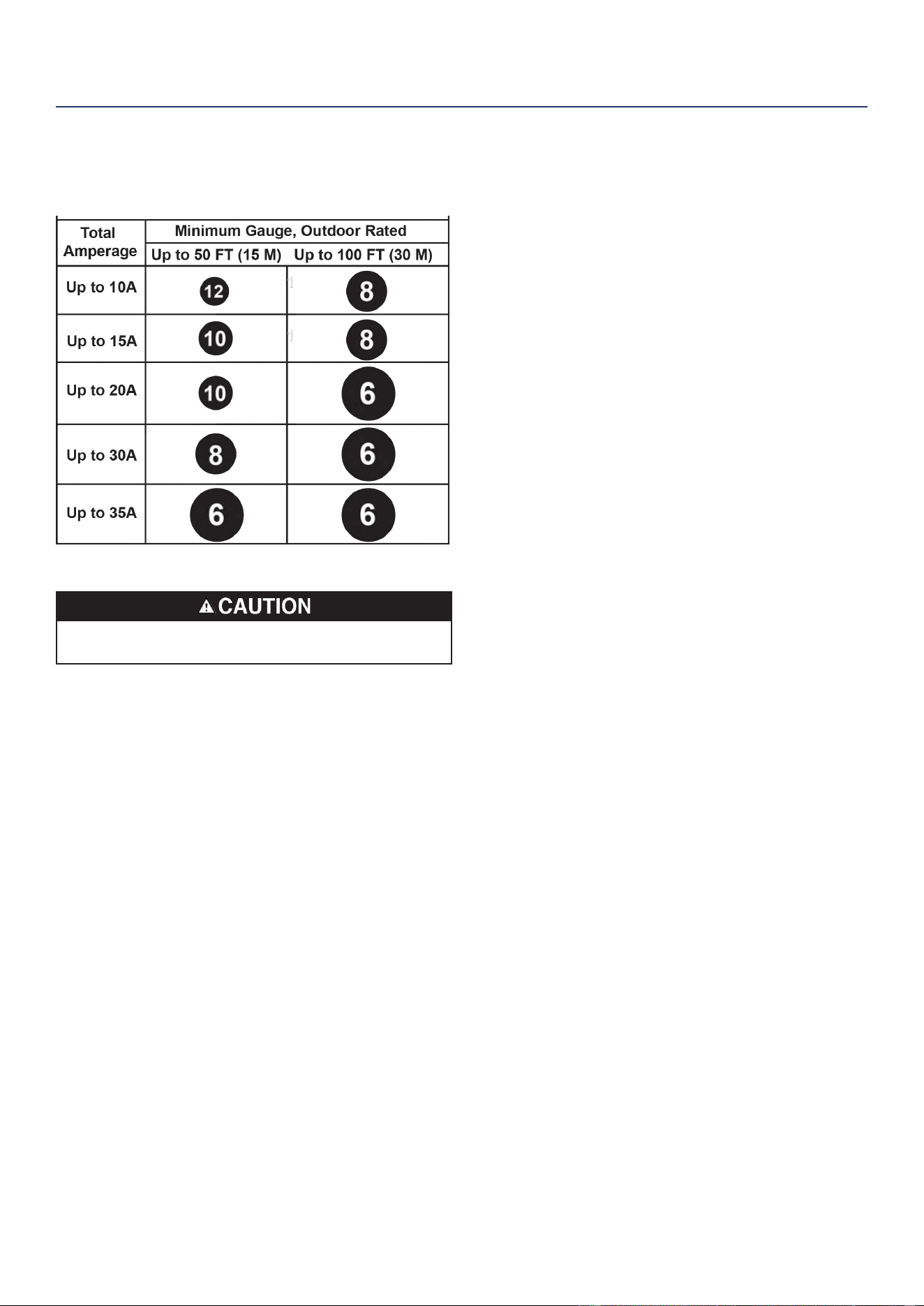
EXTENSION CORD SIZING
Only use grounded 3-prong extension cords marked for
outdoor use that are rated for the electrical load.
TRANSPORTING
Weight hazard. ALWAYS have assistance when lifting
the generator.
• Allow the generator to cool a minimum of 30 minutes
before transporting.
• Replace all protective covers on the generator control
panel.
• Only use the generator’s xed frame to lift the unit or
attach any load restraints such as ropes or tie-down
straps. DO NOT attempt to lift or secure the generator
by holding onto any of its other components.
• Keep the unit level during transport to minimize the
possibility of fuel leakage or, if possible, drain the fuel
or run the engine until the fuel tank is empty before
transport.
OPERATION
18 | Westinghouse Outdoor Power Equipment, LLC
MAINTENANCE
Fire hazard. DO NOT up-end the generator or place it on
its side. Fuel or oil can leak and damage to the generator
may occur.
Accidental start-up. Disconnect the spark plug boot from
the spark plug when performing maintenance on the
generator.
MAINTENANCE SCHEDULE
Regular maintenance will improve performance and
extend the service life of the generator. Follow the hourly
or calendar intervals, whichever occurs rst. More frequent
service is required when operating in adverse conditions
as noted below.
Before Each Use
Check engine oil
After First 25 Hours or First Month
Change engine oil
After 50 Hours or Every 6 Months
Change engine oil
1
Clean air lter
2
After 100 Hours or Every 6 Months
Inspect/clean spark arrestor
Inspect/clean spark plug
Fuel valve maintenance
Inspect/adjust valve clearance
3
After 300 Hours or Every Year
Replace spark plug
Replace air lter
1
Change oil every month when operating under heavy
load or in high temperatures.
2
Clean more often under dirty or dusty conditions.
Replace air lter if it cannot be adequately cleaned.
3
Recommend service to be performed by authorized
Westinghouse service dealer.
MAINTENANCE REMINDERS
Maintenance reminder codes will be shown on the Data
Display based on unit Lifetime Hours. The maintenance
codes will be displayed until the unit is turned off. Refer to
the Maintenance section for specic procedures.
Maintenance Code Required Maintenance
P25 Change engine oil
P50
• Change engine oil
• Clean air lter
Maintenance Code Required Maintenance
P100
• Change engine oil
• Clean air lter
• Fuel valve maintenance
• Inspect/adjust valve clearance
MAINTENANCE REPLACEMENT PARTS
Description Part Number
Air lter 5941
Oil drain plug crush washer 94007
Spark arrestor 6790
Spark plug 97108 (F7TC)
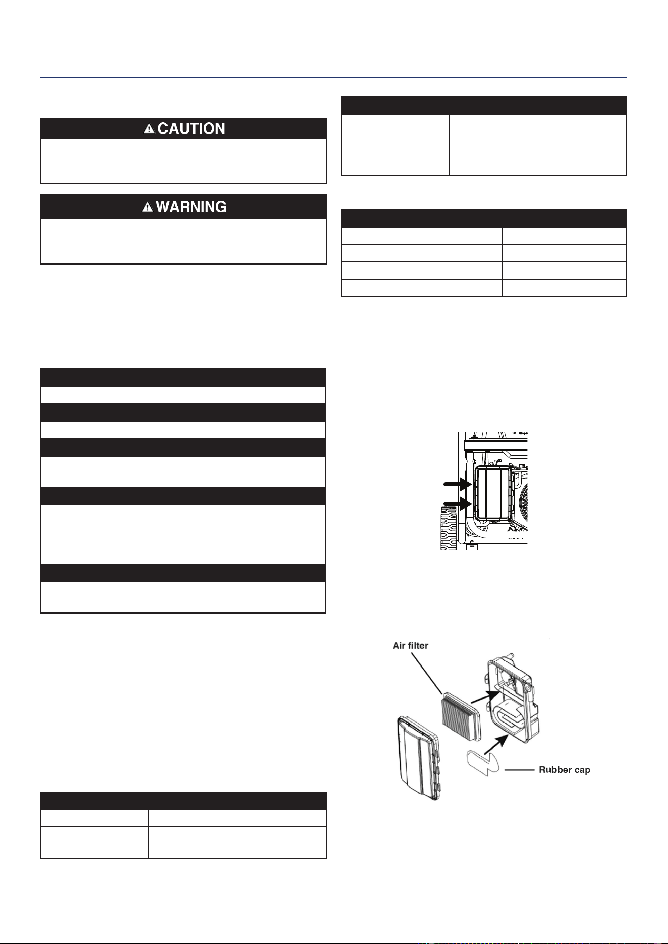
AIR FILTER MAINTENANCE
The air lter must be cleaned after every 50 hours of use or
six months (frequency should be increased if the generator
is operated in a dusty environment).
1. Place the generator on a level surface and allow the
engine to cool for several minutes.
2. Release the clips and remove the air lter cover.
3. Clean the air lter with compressed air. Replace if
damaged.
4. Make sure the air lter and rubber cap are correctly
installed. Install the air lter cover and secure it in place
with the cover clips.
MAINTENANCE
Westinghouse Outdoor Power Equipment, LLC | 19
MAINTENANCE
ENGINE OIL LEVEL CHECK
Avoid skin contact with engine oil. Wear protective
clothing and equipment. Wash all exposed skin with
soap and water.
NOTICE
ALWAYS use the specied engine oil. Failure to use the
specied engine oil can cause accelerated wear and/or
shorten the life of the engine.
When using the generator under dirty, dusty conditions or
in extremely hot weather, change the oil more frequently.
Ambient air temperature will affect engine oil performance.
Change the type of engine oil used based on weather
conditions.
Check the engine oil level before each use or every 8
hours of operation.
1. Place the generator on a level surface and allow the
engine to cool for several minutes.
2. With a damp rag, clean around the oil dipstick.
3. Remove the oil dipstick and wipe the dipstick clean.
4. Insert the dipstick into the oil ller neck without screwing
it in. Remove the dipstick and verify that the oil level
is within safe operating range between the low (L) and
high (H) marks on the dipstick.
Safe Operating Range
L
H
5. If low, add recommended engine oil incrementally and
recheck until the level is between the L and H marks on
the dipstick. DO NOT overll. If over the H mark on the
dipstick, drain oil to reduce the oil level to the full mark.
6. Replace the oil dipstick and hand-tighten.
ENGINE OIL CHANGE
When using the generator under dirty, dusty conditions or
in extremely hot weather, change the oil more frequently.
Change the oil while the engine is still warm from operation.
1. Place the generator on a level surface and allow the
engine to cool for several minutes.
2. With a damp rag, clean around the oil dipstick. Remove
the dipstick and wipe clean.
3. Place an oil pan (or suitable container) under the oil
drain bolt.
4. Using a 10mm wrench, remove the oil drain bolt and
allow the oil the to drain.
Drain bolt
Oil pan
5. Install the oil drain bolt and tighten securely.
Note: A new oil drain plug crush washer is recommended
at each oil change.
6. Slowly pour oil into the oil ller neck until oil the level
is between the L and H marks on the dipstick. Stop
frequently to check the oil level. DO NOT overll.
Maximum oil capacity: 0.74 Quart (0.7 Liter)
7. Install the oil dipstick and hand-tighten.
NOTICE
DO NOT pollute. Follow the guidelines of the EPA or other
governmental agencies for proper disposal of hazardous
materials. Consult local authorities or reclamation facility.
20 | Westinghouse Outdoor Power Equipment, LLC
MAINTENANCE
SPARK PLUG MAINTENANCE
Inspect and clean the spark plug after every 100 hours of
use or six months. Replace the spark plug after 300 hours
of use or every year.
NOTICE
ALWAYS use the Westinghouse OEM or compatible
non-resistor-type spark plug. Use of resistor-type spark
plug can result in rough idling, misre, or may prevent
the engine from starting.
1. Place the generator on a level surface and allow the
engine to cool.
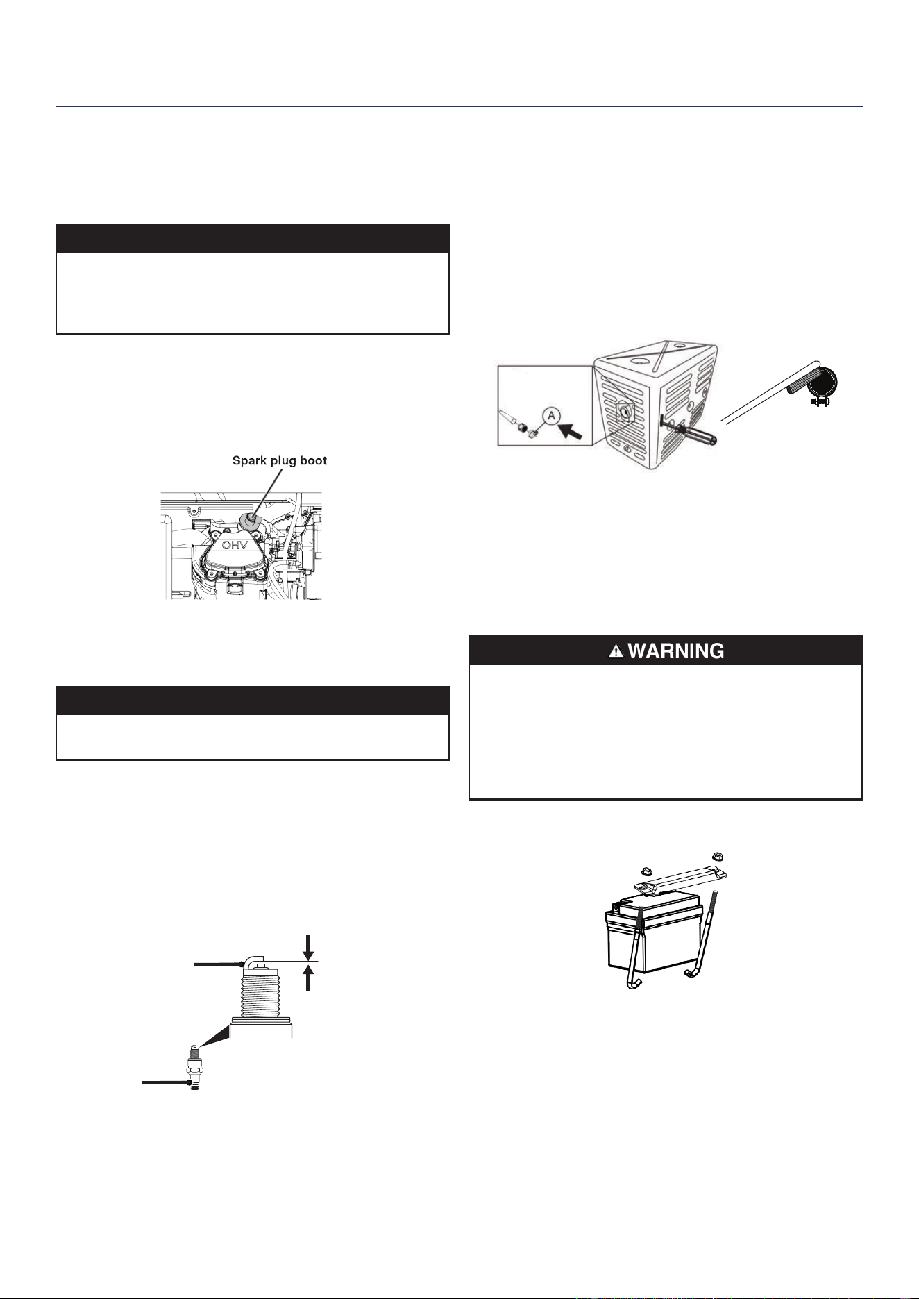
2. Remove the spark plug boot by rmly pulling the spark
boot directly away from the engine.
3. Clean the area around the spark plug.
4. Remove the spark plug with the included spark plug
socket wrench.
NOTICE
NEVER apply any side load or move the spark plug
laterally when removing the spark plug.
5. Inspect the spark plug. Replace if electrodes are
pitted, burned, or the insulator is cracked. Only use a
recommended replacement plug.
6. Measure the spark plug electrode gap with a wire-type
feeler gauge. If necessary, correct the gap by carefully
bending the side electrode.
Spark plug gap: 0.024 – 0.032 in. (0.60 – 0.80 mm)
0.024 - 0.032 in.
(0.60 - 0.80 mm)
Insulator
Side
Electrode
7. Carefully install the spark plug nger tight, then tighten
as additional 3/8 to 1/2 turn with the spark plug wrench.
8. Attach the spark plug boot.
SPARK ARRESTOR SERVICE
Allow the mufer to cool completely before servicing the
spark arrestor. Check and clean the spark arrestor after
every 100 hours of use or six months. Failure to clean the
spark arrestor will result in degraded engine performance.
1. Place the generator on a level surface.
2. Slide in screwdriver into side slot and remove screw
holding clamp (A) on spark arrestor. Pull out spark
arrestor assembly.
3. Carefully remove the carbon deposits from the spark
arrestor screen with a wire brush. The spark arrestor
must be free of breaks and tears. Replace the spark
arrestor if damaged.
4. Reinstall the spark arrestor.
BATTERY REPLACEMENT
Keep battery terminals covered at all times. The
generator is shipped with a lithium ion (Li-Ion) battery.
Exposed metal positive and negative terminals can
short-circuit when they come into contact with metal
objects, igniting the cell’s internal materials and forcibly
expelling burning contents, resulting in res, explosions,
serious injuries and even death.
1. Loosen and remove the bolts securing the battery hold-
down plate and remove the plate.
2. Disconnect the quick-connect plugs and remove the
battery from the unit.
3. Disconnect the quick-disconnect cable leads from the
battery.
4. On the replacement battery, connect the white (-) quick-
connect cable to the battery negative terminal. Slide the
rubber boot over the connection hardware.
5. Connect the red (+) quick-connect cable to the battery
positive terminal. Slide the rubber boot over the
Westinghouse Outdoor Power Equipment, LLC | 21
connection hardware.
6. Install the battery into the generator. Reinstall the battery
hold-down plate and tighten the bolts.
7. Connect the quick-connect plug.
NOTICE
Dispose of the used battery properly according to the
guidelines established by your local or state government.
STORAGE
Proper storage preparation is required for trouble-free
operation and generator longevity.
NOTICE
Gasoline stored for as little as 30 days can deteriorate,
causing gum, varnish, and corrosive buildup in fuel lines,
fuel passages, and the engine. This corrosive buildup
restricts the ow of fuel, which can prevent the engine
from starting after a prolonged storage period. The use
of fuel stabilizer signicantly increases the storage life of
gasoline. Full-time use of fuel stabilizer is recommended.
Follow the manufacturer’s instructions for use.
STORAGE TIME RECOMMENDED PROCEDURE
Less than 1 month No service required.
2 to 6 months
Fill with fresh gasoline and add
gasoline stabilizer. Drain the
carburetor oat bowl.
6 months or longer
Drain the fuel tank and carburetor
oat bowl.
SHORT TERM STORAGE
• Allow the generator to cool a minimum of 30 minutes
before storage.
• Replace all protective covers on the generator control
panel.
• Wipe the generator with a moist cloth. Clean any debris
from the mufer cooling vents.
• Store the generator in a well-ventilated, dry location
away from sparks, open ames, pilot lights, heat, and
other sources of ignition such as areas with a spark-
producing electric motor or where power tools are
operated.
• DO NOT store the generator, or gasoline near furnaces,
water heaters, or any other appliances that produce
heat or have automatic ignitions.
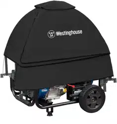
• With the engine and exhaust system cool and all
surfaces dry, cover the generator to keep out dust. DO
NOT use a plastic sheet as a dust cover. Non-porous
materials trap moisture and promote rust and corrosion.
LONG TERM STORAGE
Even properly stabilized fuel can leave residue and cause
corrosion if left long term. If storing the generator for two to
six months, drain the oat bowl to prevent gum and varnish
buildup in the carburetor.
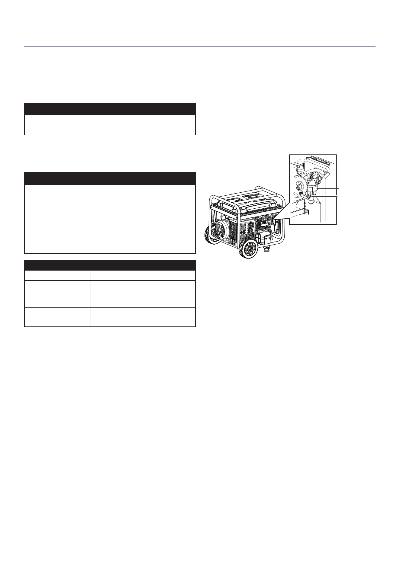
DRAINING THE FLOAT BOWL
1. Turn the fuel tank valve to the OFF position.
2. Locate the drain screw on the bottom of the carburetor
oat bowl.
Drain screw
Float bowl
3. Place an appropriate gasoline container under the drain
screw to catch the drained fuel.
4. Loosen the oat bowl drain screw and allow the fuel to
drain. Tighten the oat bowl drain screw.
DRAINING THE FUEL TANK
If storing the generator for longer than six months, drain
the fuel tank to prevent fuel separation, deterioration, and
deposits in the fuel system.
1. Unscrew the fuel tank cap. Remove the fuel screen lter
by slightly compressing it while removing it from the
tank.
2. Using a commercially available gasoline hand pump
(not included), siphon the gasoline from the fuel tank
into an approved gasoline container. DO NOT use an
electric pump.
3. Reinstall the fuel screen lter and the fuel tank cap.
4. Start the generator and allow it to run until the generator
engine stops.
5. Push the Run/Stop switch to the Stop position.
6. Remove the spark plug.
7. Put a teaspoon of engine oil into the cylinder and pull the
recoil handle until resistance is felt. At this position the
piston is coming up on its compression stroke and both
valves are closed. Storing the engine in this position will
help prevent internal corrosion.
MAINTENANCE
22 | Westinghouse Outdoor Power Equipment, LLC
8. Return the recoil handle gently.
9. Reinstall the spark plug. Leave the spark plug boot
disconnected to prevent accidental starting.
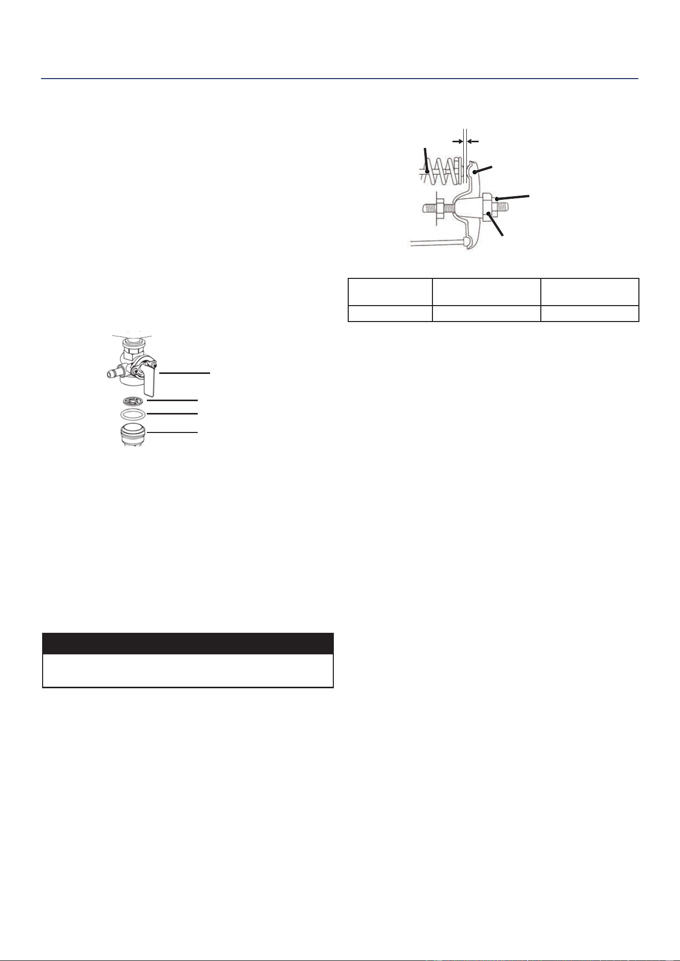
FUEL VALVE MAINTENANCE
The fuel valve is equipped with a fuel sediment cup, screen,
and o-ring. The fuel valve does not require servicing if the
unit is properly maintained with fresh, clean fuel. If fuel-
related troubleshooting is required, perform fuel valve
maintenance.
1. Allow the generator to cool completely.
2. Turn the fuel valve to the OFF position.
3. Remove the sediment cup from the fuel valve. Remove
the o-ring and screen.
Fuel valve
Screen
O-ring
Cup
4. Wash the sediment cup, o-ring, and screen in a
nonammable solvent. Dry thoroughly.
5. Place the screen and o-ring into the fuel valve. Install
the sediment cup and tighten securely.
6. Turn the fuel valve to the ON position and check for
leaks. Replace the fuel valve if there is any leakage.
7. Turn the fuel valve to the ON position and check for
leaks. Replace the fuel valve if there is any leakage.
VALVE CLEARANCE
NOTICE
Checking and adjusting valve clearance must be done
when the engine is cold.
1. Remove the rocker arm cover and carefully remove
the gasket. If the gasket is torn or damaged, it must be
replaced.
2. Remove the spark plug so the engine can be rotated
more easily.
3. Rotate the engine to top dead center (TDC) by pulling
the recoil handle slowly. Looking through the spark plug
hole, the piston should be at the top (both valves are
closed).
4. Both the rocker arms should be loose at TDC on the
compression stroke. If they are not, rotate the engine
360°.
5. Insert a feeler gauge between the rocker arm and the
valve stem to measure valve clearance.
Pivot
Adjusting Nut
Valve Stem
Rocker Arm
Rocker Arm Pivot
Intake Valve Exhaust Valve
Valve Clearance
0.0031 – 0.0047 in
(0.08 – 0.12 mm)
0.0051 – 0.0067 in
(0.13 – 0.17 mm)
Torque 8-12 N•m 8-12 N•m
6. If an adjustment is necessary, hold the rocker arm pivot
and loosen the pivot adjusting nut.
7. Turn the rocker arm pivot to obtain the specied
clearance. Hold the rocker arm pivot and re-tighten the
pivot adjusting nut to the specied torque.
Torque: 106 inch-pound (12 N•m)
8. Perform this procedure for the other valve.
9. Install the gasket, rocker arm cover, and spark plug.
MAINTENANCE

Westinghouse Outdoor Power Equipment, LLC | 23
TROUBLESHOOTING
TROUBLESHOOTING
PROBLEM POSSIBLE CAUSE CORRECTION
Engine will not start
Battery switch in the OFF position. Turn battery switch to the ON position.
Out of fuel. Refuel.
Bad fuel, generator stored without treating or
draining gasoline, or refueled with bad gasoline.
Drain the fuel tank. Refuel with fresh gasoline.
Dirty air lter. Clean the air lter.
Low engine oil level stopped generator.
If low oil LED illuminated, turn battery switch to
the OFF position. Add engine oil.
Spark plug wet with fuel (ooded engine).
Wait ve minutes. Turn battery switch to the
OFF position. Pull recoil handle rapidly several
times. If the generator does not start, remove
spark plug and dry.
Spark plug faulty, fouled, or improperly gapped. Gap or replace the spark plug. Reinstall.
Fuel lter restricted, fuel system malfunction, fuel
pump failure, ignition malfunction, valves stuck,
etc.
Contact Westinghouse customer service toll-
free at 1 (855) 944-3571.
Battery drained.
Use the recoil handle to start the generator.
Charge the battery.
Choke partially open or closed due to weak or
disconnected battery.
Manually set the choke. See Maintenance
section.
Engine starts, then shuts down
Out of fuel. Refuel.
Incorrect engine oil level. Check engine oil level.
Dirty air lter. Clean the air lter.
Contaminated fuel. Drain the fuel tank. Refuel with fresh gasoline.
Defective low oil level switch.
Contact Westinghouse customer service toll-
free at 1 (855) 944-3571.
Engine lacks power
Air lter restricted. Clean or replace air lter.
Bad fuel, generator stored without treating or
draining gasoline, or refueled with bad gasoline.
Drain the fuel tank. Refuel with fresh gasoline.
Fuel lter restricted, fuel system malfunction, fuel
pump failure, ignition malfunction, valves stuck,
etc.
Contact Westinghouse customer service toll-
free at 1 (855) 944-3571.
Engine runs rough or bogs when load
applied
Dirty air lter. Clean the air lter.
Generator overloaded. Unplug some devices.
Faulty power tool or appliance.
Replace or repair tool or appliance. Stop and
restart the engine.
Fuel lter restricted, fuel system malfunction, fuel
pump failure, ignition malfunction, valves stuck,
etc.
Contact Westinghouse customer service toll-
free at 1 (855) 944-3571.
No power at AC receptacles
AC circuit breaker/s tripped. Check AC loads and reset circuit breaker/s.
Faulty power tool or appliance.
Replace or repair tool or appliance. Stop and
restart the engine.
Faulty generator.
Contact Westinghouse customer service toll-
free at 1 (855) 944-3571.
TROUBLESHOOTING
24 | Westinghouse Outdoor Power Equipment, LLC
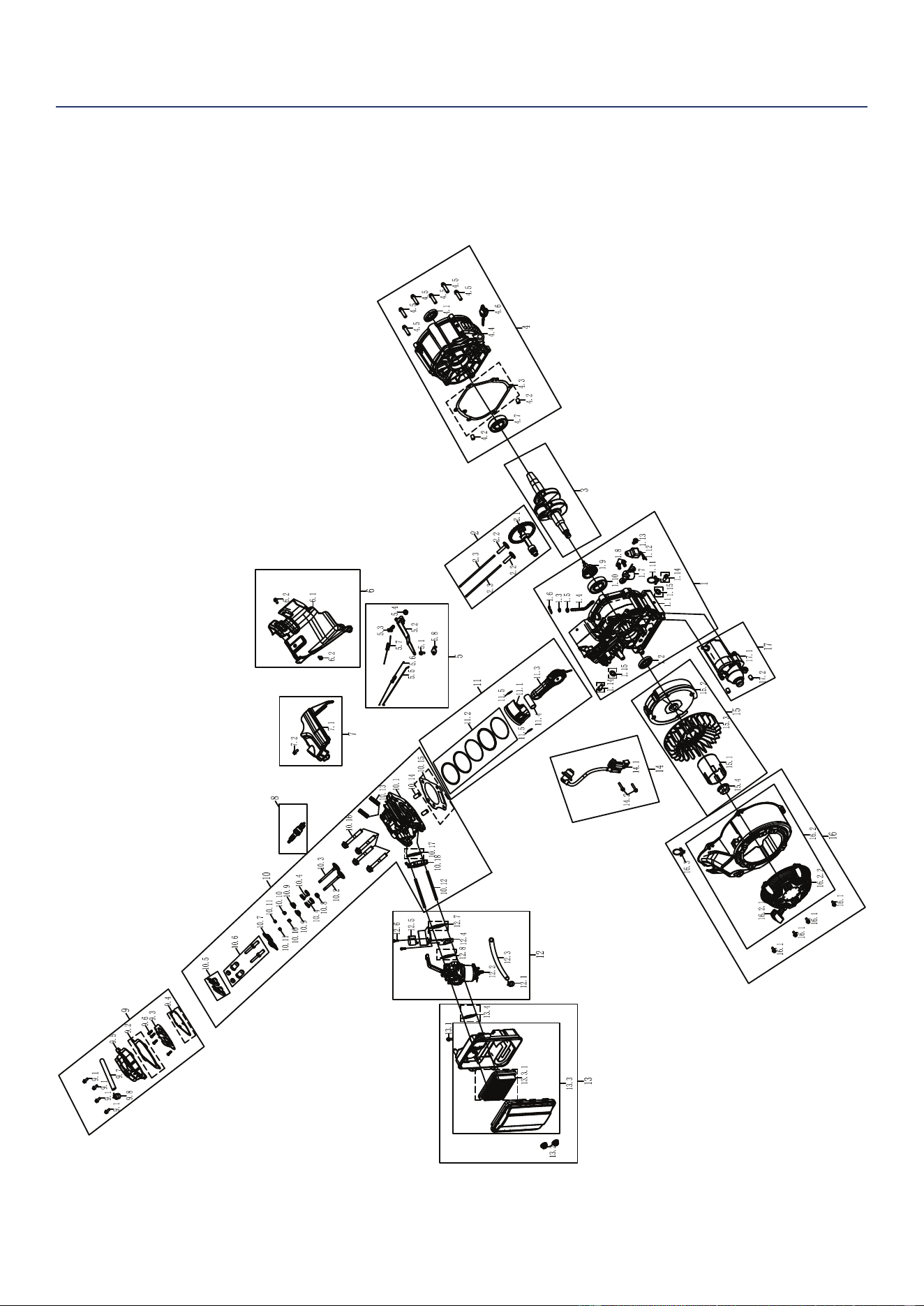
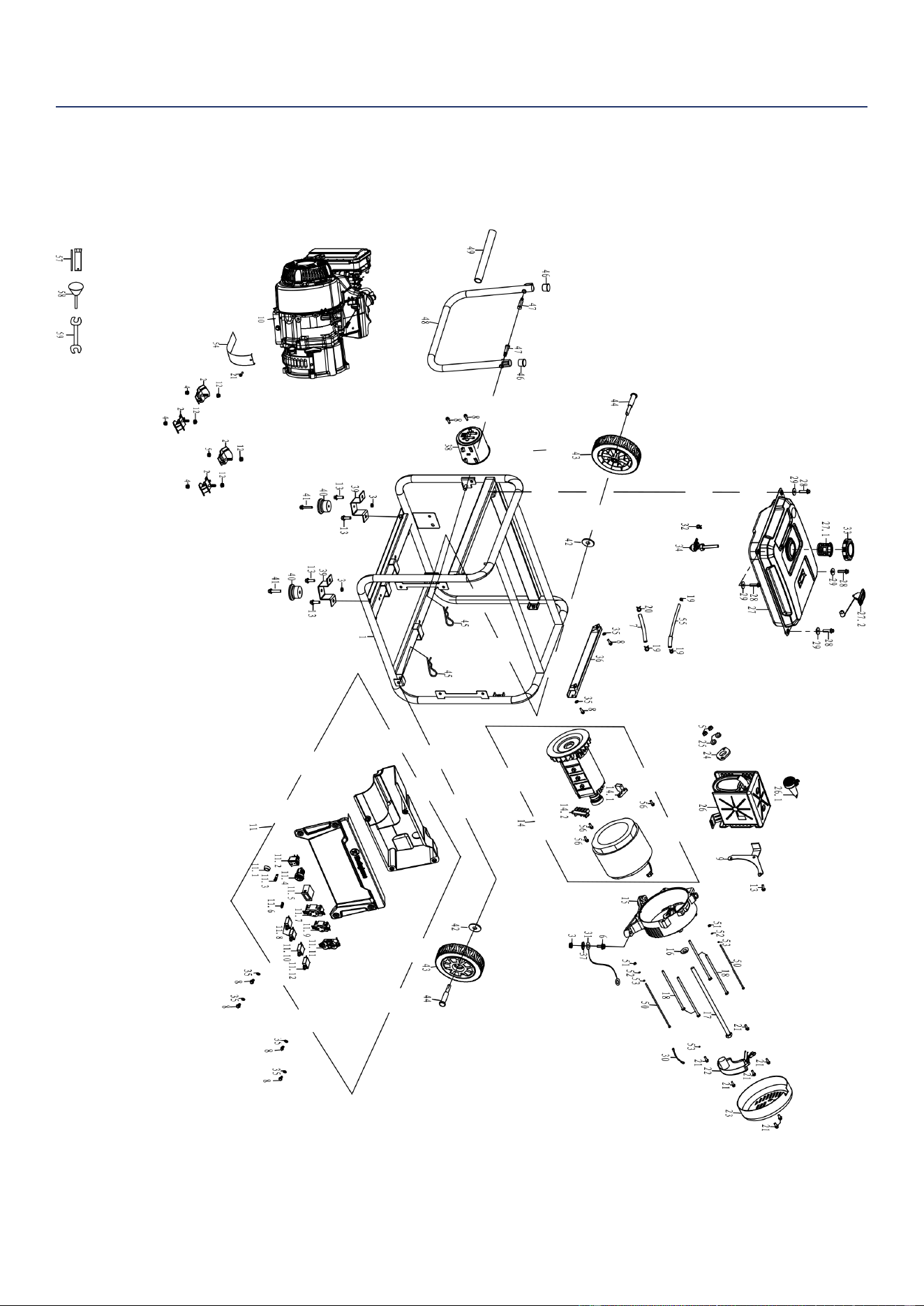
EXPLODED VIEWS AND PARTS LIST
ENGINE EXPLODED VIEW
EXPLODED VIEWS

Westinghouse Outdoor Power Equipment, LLC | 25
EXPLODED VIEWS
ENGINE PARTS LIST
NO. PART # DESCRIPTION
1 50120043 CRANKCASE ASSEMBLY
1.1 400202 CRANKCASE
1.2 93509 CRANKCASE OIL SEAL
1.3 93520 SWING ROD OIL SEAL
1.4 403901 SWINGING ROD
1.5 96804 SWINGING ROD GASKET
1.6 383902 RETAINING CLIP
1.7 245106 OIL SENSOR
1.8 91329 BOLT M6*16 GB/T5787-1986
1.9 404301 CENTRIFUGAL GOVERNOR GEAR
ASSEMBLY
1.10 93012 BEARING
1.11 240801 CABLE CLIP
1.12 245104 OIL PROTECTOR
1.13 91325 BOLT M6*12 GB/T5787-1986
1.14 91816 BOLT M10*1.25*15
1.15 94007 OIL DRAIN BOLT WASHER
2 50150010 CAMSHAFT ASSEMBLY
2.1 402002 CAMSHAFT ASSEMBLY
2.2 406101 VALVE LIFTER
2.3 401901 PUSH ROD
3 400301 CRANKSHAFT
4 50200038 CRANKCASE COVER ASSEMBLY
4.1 93509 CRANKCASE OIL SEAL
4.2 240904 CRANKCASE LOCATING PIN
4.3 96222 CRANKCASE GASKET
4.4 400101 CRANKCASE COVER
4.5 91347 BOLT M8*30 GB/T5787-1986
4.6 245601-295 DIPSTICK ASSEMBLY
4.7 93012 BEARING
5 50060027 SPEED CONTROL BRACKET
ASSEMBLY
5.1 91329 BOLT M6*16 GB/T5787-1986
5.2 404001 SPEED REGULATING ARM
5.3 91822 BOLT M6*21
5.4 90016 NUT M6 GB/T6177-2000
5.5 402701 THROTTLE LEVER
5.6 404201 SPRING C
5.7 404101 SPRING B
5.8 407701 SPEED CONTROL BRACKET
6 50670001 LOWER GUARD ASSEMBLY
6.1 407601 LOWER GUARD
6.2 91325 BOLT M6*12 GB/T5787-1986
7 50130014 WIND-LEAD-COVER ASSEMBLY
7.1 407501 WIND-LEAD-COVER
7.2 91325 BOLT M6*12 GB/T5787-1986
8 97108 SPARK PLUG
9 50010030 CYLINDER HEAD COVER ASSEMBLY
9.1 91329 BOLT M6*16 GB/T5787-1986
9.2 96225 CYLINDER HEAD COVER GASKET
9.3 401102 CYLINDER HEAD INTERNAL COVER
9.4 96226 CYLINDER HEAD INTERNAL COVER
GASKET
NO. PART # DESCRIPTION
9.5 401101 CYLINDER HEAD COVER
9.6 92036 SCREW
9.7 95603 BREATHER TUBE
9.8 94435 BREATHER TUBE CLIP
10 50020069 CYLINDER HEAD ASSEMBLY
10.1 401002 CYLINDER HEAD
10.2 401701 INTAKE VALVE
10.3 405901 EXHAUST VALVE
10.4 406001 VALVE SPRING
10.5 402101 ROCKING ARM
10.6 91818 BOLT
10.7 402201 VALVE RETAINER ASSEMBLY
10.8 241806 VALVE SEAL
10.9 241817 VALVE SPRING RETAINER
10.10 329930 VALVE LOCK CLIP
10.11 241804 TOP CAP
10.12 91022 DOUBLE END BOLT M6*95
10.13 91007 DOUBLE END BOLT M8*38
10.14 400901 CYLINDER HEAD LOCATING PIN
10.15 96223 CYLINDER HEAD GASKET
10.16 91452 BOLT M10*1.25*70 GB/T5789-1986
10.17 96235 GASKET
10.18 402301 CARBURETOR CONNECTION BLOCK
11 50050021 PISTON & PISTON RING ASSEMBLY
11.1 401201 PISTON
11.2 401601 PISTON RING ASSEMBLY
11.3 401501 CONNECTING ROD ASSEMBLY
11.4 405501 PISTON PIN
11.5 241301 PISTON PIN RING
12 50040098 CARBURETOR ASSEMBLY
12.1 94403 FUEL LINE CLAMP
12.2 402806 CARBURETOR ASSEMBLY
12.3 95407L FUEL LINE
12.4 249906 STEPPER MOTOR BRACKET
12.5 249904 STEPPER MOTOR
12.6 92217 BOLT ASSEMBLY M4*8
12.7 96224 GASKET
12.8 94229 AIR FILTER GASKET
13 50030057 AIR FILTER ASSEMBLY
13.1 91329 BOLT M6*16 GB/T5787-1986
13.2 90016 NUT M6 GB/T6177-2000
13.3 402901 AIR FILTER ASSEMBLY
13.3.1 5941 AIR FILTER
13.4 94229 AIR FILTER GASKET
14 50100034 IGNITER ASSEMBLY
14.1 97514 IGNITER
14.2 91331 BOLT M6*25 GB/T5787-1986
15 50180021 FLYWHEEL ASSEMBLY
15.1 244508 STARTER PULLEY
15.2 240413 FLYWHEEL ASSEMBLY
15.3 404601 IMPELLER
15.4 90003 NUT M14*1.5 GB/T6177-2000
16 50090067 RECOIL STARTER ASSEMBLY

26 | Westinghouse Outdoor Power Equipment, LLC
ENGINE PARTS LIST CONTINUED
NO. PART # DESCRIPTION
16.1 91325 BOLT M6*12 GB/T5787-1986
16.2 404707-221A RECOIL STARTER ASSEMBLY
16.2.1 5943 RECOIL HANDLE
16.2.2 5942-221 START PULLER RECOIL COVER
16.3 260801 CABLE CLIP
17 50260012 STARTER MOTOR ASSEMBLY
17.1 97459 STARTING MOTOR ASSEMBLY
17.2 240910 LOCATING PIN
Westinghouse Outdoor Power Equipment, LLC | 27
GENERATOR EXPLODED VIEW
EXPLODED VIEWS

28 | Westinghouse Outdoor Power Equipment, LLC
EXPLODED VIEWS
GENERATOR PARTS LIST
NO. PART # DESCRIPTION
1 60070034 FRAME ASSEMBLY
1.1 774331-116 FRAME
1.2 531318 ISOLATION SUPPORT
1.3 90016 NUT M6
1.4 90018 NUT M8
1.5 91325 BOLT M6X12
1.6 91327 BOLT M6X12
1.7 544301 FRAME WIRE
1.8 96120 PAPER WASHER
1.9 530324-116 MOVABLE RECTANGLE PIPE
1.10 94002 TOOTH WASHER 6
2 60200014 BATTERY BRACKET ASSEMBLY
2.1 511085 BATTERY
2.2 511086 BATTERY PULL ROD
2.3 501133 BATTERY HOLDER
2.4 512058 BATTERY WIRING ASSEMBLY
2.5 90016 NUT M6
3 60150028 FOOT BRACKET ASSEMBLY
3.1 90023 NUT M6
3.2 91343 BOLT M8X16
3.3 525314-116 FOOT BRACKET ASSEMBLY
3.4 531115 FOOT BRACKET ISOLATION
SUPPORT
3.5 91333 BOLT M6X28
4 60590019 ENGINE ASSEMBLY
4.1 1148274120022 ENGINE ASSEMBLY DH275
4.2 91322 BOLT M5X12
4.3 539602 CRANKCASE COVER SHIELD
5 60180034 HANDLE WELDING ASSEMBLY
5.1 527613 HANDLE PLUG
5.2 527611 HANDLE MOUNTING BOLT
5.3 526639-116 HANDLE
5.4 528609 HANDLE RUBBER SLEEVE
6 60570005 CARBON CANISTER ASSEMBLY
6.1 95021 CARBON CANISTER AND AIR
FILTER CONNECTING PIPE
6.2 91327 BOLT M6X12
6.3 94402 FUEL LINE CLAMP 8.5
6.4 94408 FUEL LINE CLAMP 10
6.5 543601L CARBON CANISTER ASSEMBLY
6.6 95020 CARBON CANISTER AND FUEL
TANK CONNECTING PIPE
6.7 94423 FUEL LINE CLAMP 9
7 60040081 PANEL ASSEMBLY
7.1 91327 BOLT M6X12
7.2 714362 PANEL ASSEMBLY
7.2.1 536002 SWITCH
7.2.2 6387 SOCKET
7.2.3 6502 ENGINE SWITCH
7.2.4 6393 INDICATOR LIGHT
7.2.5 6041 TIME ACCUMULATOR
7.2.6 6488 SMART SWITCH READY
7.2.7 6386 GROUND TERMINAL ASSEMBLY
NO. PART # DESCRIPTION
7.2.8 6385 L14-30R RECEPTACLE
7.2.9 6848 WATERPROOF CAP
7.2.10 6441-22 THERMAL PROTECTOR
7.2.11 6015 RV SOCKET
7.2.12 6849 WATERPROOF CAP
7.2.13 6441-30 THERMAL PROTECTOR
7.2.14 6032 L5-20R RECEPTACLE
7.2.15 6846 WATERPROOF CAP
7.2.16 6441-20 THERMAL PROTECTOR
7.3 96120 PAPER WASHER
8 60060028 WHEEL ASSEMBLY
8.1 94224 FLAT WASHER
8.2 523308 WHEEL
8.3 524320 AXLE
8.4 548302 COTTER PIN
9 60010046 FUEL TANK ASSEMBLY
9.1 700271L-116 FUEL TANK
9.1.1 518801 FUEL TANK FILTER
9.1.2 6785 FUEL GAUGE
9.2 519215 FUEL CAP
9.3 91460 BOLT M6X25
9.4 518202 FUEL SWITCH
9.5 94403 FUEL LINE CLAMP 7.5
10 60030033 EXHAUST MUFFLER ASSEMBLY
10.1 90011 NUT M8
10.2 520308 MUFFLER MOUNTING BRACKET
10.3 91343 BOLT M8X16
10.4 96252 EXHAUST GASKET
10.5 94206 SPRING WASHER 8
10.6 705658 MUFFLER
10.6.1 6790 SPARK ARRESTER
11 60580027 ALTERNATOR ASSEMBLY
11.1 755537 ALTERNATOR ASSEMBLY
11.1.1 599019 CARBON BRUSH
11.1.2 6560 TERMINAL ASSEMBLY
11.2 532303-052 TAIL BRACKET FIXING PLATE
11.3 94204 SPRING WASHER 5
11.4 532306 ALTERNATOR TAIL BRACKET
11.5 96813 GASKET 10.5×30×4
11.6 91721 BOLT M10X1.25X225
11.7 91619 BOLT M6X140
11.8 91322 BOLT M5X12
11.9 534806 AVR
11.10 533302-221 ALTERNATOR TAIL COVER
11.11 91323 BOLT M5X16
11.12 91513 BOLT M5X175
11.13 90009 NUT M5
11.14 544604 SHORT WIRE
12 99010 SPARK PLUG SLEEVE
13 500942 FUNNEL
14 99025 WRENCH
15 511076 CHARGER
Westinghouse Outdoor Power Equipment, LLC | 29
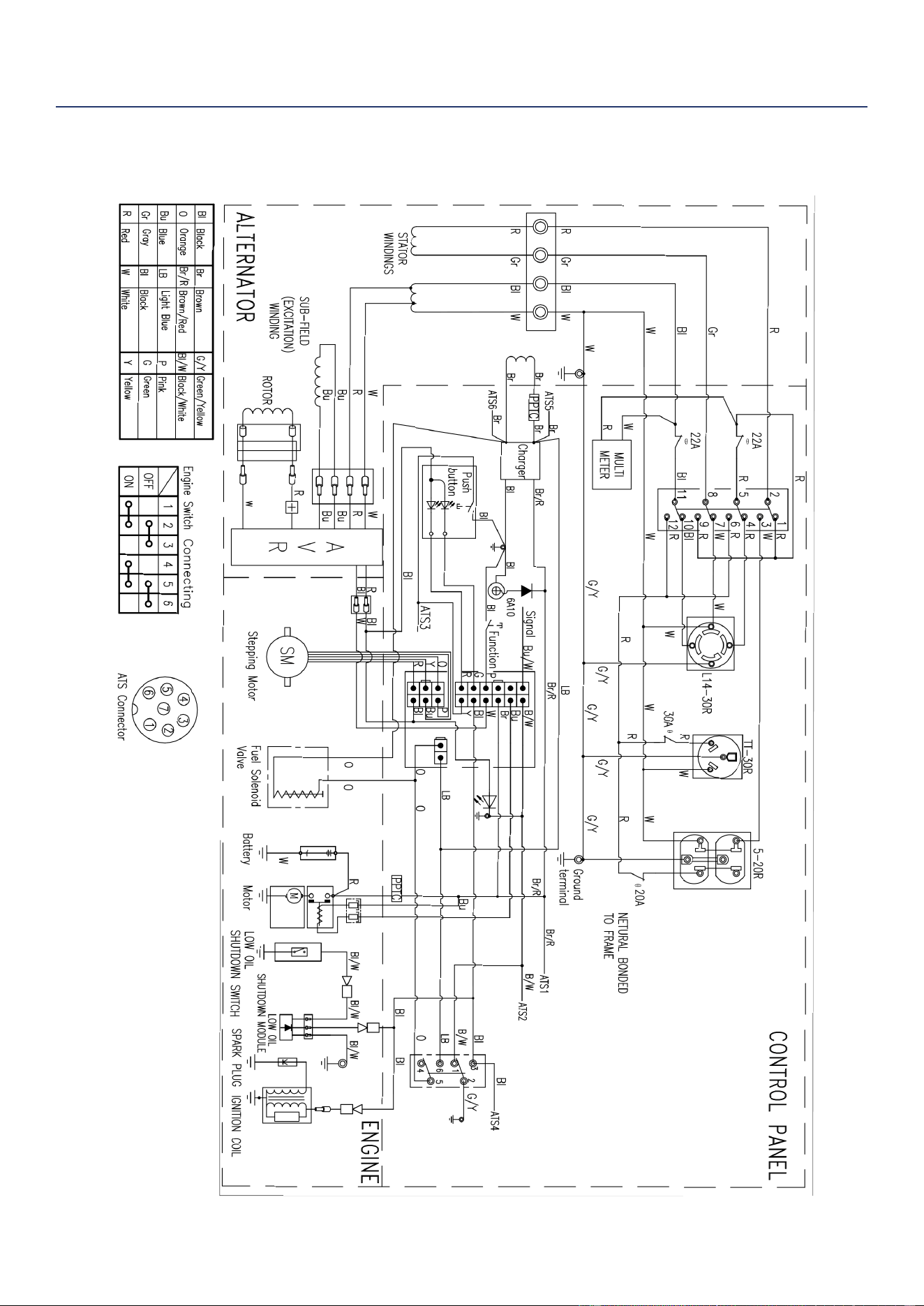
SCHEMATICS
SCHEMATICS
SCHEMATICS

30 | Westinghouse Outdoor Power Equipment, LLC
NO DEVUELVA ESTE PRODUCTO A LA TIENDA
Si tiene preguntas o necesita ayuda, llame al servicio al
cliente al 855-944-3571.
MANUAL DE USUARIO
ESPAÑOL
WGen5300
Generador Portátil
Gasolina: 5300 Vatios en Funcionamiento | 6600 Vatios de arranque
TABLA DE CONTENIDO
INTRODUCCIÓN
DESCARGOS DE RESPONSABILIDAD ...............................31
TODOS LOS DERECHOS RESERVADOS
...........................31
GUARDA ESTAS INSTRUCCIONES
.....................................31
ESPECIFICACIONES
ESPECIFICACIONES ............................................................32
SEGURIDAD
DEFINICIONES DE SEGURIDAD .........................................33
SÍMBOLOS DE SEGURIDAD Y SIGNIFICADO
....................33
LAS INSTRUCCIONES DE SEGURIDAD
.............................34
PRECAUCIONES GENERALES DE SEGURIDAD
...............34
SEGURIDAD DEL COMBUSTIBLE
.......................................35
GASOLINA Y VAPOR DE GASOLINA (GAS)
........................35
CALCOMANÍAS DE SEGURIDAD
.........................................36
COMPONENTES
COMPONENTES DEL PANEL DE CONTROL ......................37
COMPONENTES DEL GENERADOR
...................................38
MONTAJE
CONTENIDO DE LA CAJA ....................................................39
INSTALE PIES Y RUEDAS
....................................................39
LLENADO DE ACEITE INICIAL
.............................................40
COMBUSTIBLE
.....................................................................40
CONECTAR LA BATERÍA
......................................................41
OPERACIÓN
CUBICACIÓN DEL GENERADOR .........................................42
TOMA DE TIERRA
.................................................................42
OPERACIÓN A GRAN ALTITUD
............................................43
INTERRUPTOR SELECTOR DE VOLTAJE
...........................43
ANTES DE ARRANCAR EL GENERADOR
........................... 43
ARRANCAR EL MOTOR
.......................................................43
PARAR EL MOTOR
................................................................44
FRECUENCIA DE USO
.........................................................44
DISYUNTORES DE CA
..........................................................44
CAPACIDAD DEL GENERADOR
..........................................44
GESTIÓN DE ENERGÍA
........................................................45
CABLES DE EXTENSIÓN
.....................................................45
TAMAÑO DEL CABLE DE EXTENSIÓN
................................46
TRANSPORTE
....................................................................... 46
MANTENIMIENTO
PROGRAMA DE MANTENIMIENTO .....................................47
RECORDATORIOS DE MANTENIMIENTO
...........................47
PIEZAS DE REPUESTO PARA MANTENIMIENTO
..............47
MANTENIMIENTO DEL FILTRO DE AIRE
.............................47
DEL MOTOR
..........................................................................48
CAMBIO DE ACEITE DEL MOTOR
.......................................48
MANTENIMIENTO DE BUJÍAS
..............................................49
SERVICIO DE APAGACHISPAS
.........................................49
CAMBIO DE BATERÍA
...........................................................50
ALMACENAMIENTO
..............................................................50
DRENAJE DEL BOWL FLOTADOR
....................................... 51
DRENAJE DEL TANQUE DE COMBUSTIBLE
......................51
MANTENIMIENTO DE LA VÁLVULA DE COMBUSTIBLE
....51
SOLUCIÓN DE PROBLEMAS
SOLUCIÓN DE PROBLEMAS ...............................................53
Westinghouse Outdoor Power Equipment, LLC | 31
INTRODUCCIÓN
ADVERTENCIA: La operación, el servicio y el mantenimiento de este equipo pueden exponerlo a sustancias
químicas que incluyen gases de escape del motor, monóxido de carbono, ftalatos y plomo, que el estado de California
reconoce como causantes de cáncer y defectos de nacimiento u otros daños reproductivos. Para minimizar la
exposición, evite respirar los gases de escape y use guantes o lávese las manos con frecuencia cuando realice el
mantenimiento de este equipo. Para obtener más información, visite www.P65warnings.ca.gov.
DESCARGOS DE RESPONSABILIDAD
Toda la información, ilustraciones y especicaciones de este manual estaban vigentes en el momento de su publicación.
Las ilustraciones utilizadas en este manual están destinadas a ser vistas de referencia representativas únicamente.
Nos reservamos el derecho de realizar cualquier cambio de especicación o diseño sin previo aviso.
TODOS LOS DERECHOS RESERVADOS
Todos los derechos reservados. No se permite la reproducción de ninguna forma sin el permiso por escrito de
Westinghouse Outdoor Power Equipment, LLC.
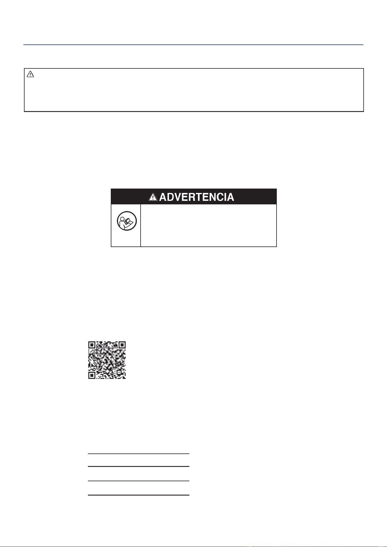
Lea este manual antes de usar o realizar
el mantenimiento de este producto. El
incumplimiento de las instrucciones y
precauciones de seguridad de este manual
puede provocar lesiones graves o la muerte.
GUARDA ESTAS INSTRUCCIONES
REGISTRACIÓN DEL PRODUCTO
Para una cobertura de garantía sin problemas, es importante registrar su generador Westinghouse.
Puede registrarse por:
• Completar y enviar por correo la tarjeta de registro del producto incluida en la caja.
• Registrando su producto en línea en: https://westinghouseoutdoorpower.com/pages/warranty-registration
• Escaneando el siguiente código QR con la cámara de su teléfono inteligente. Se le dirigirá al enlace de registro móvil.
• Envío de la siguiente información del producto a:
Westinghouse Outdoor Power
Warranty registration
777 Manor Park Drive
Columbus, OH 43228
Para su archivo
Fecha de compra:
Número de modelo:
Número de serie:
Lugar de compra:
IMPORTANTE: Conserve su recibo de compra
para una cobertura de garantía sin
problemas.
INTRODUCCIÓN

32 | Westinghouse Outdoor Power Equipment, LLC
ESPECIFICACIONES
ESPECIFICACIONES
ESPECIFICACIONES
Watts en funcionamiento: 5300
Vatios pico: 6600
Potencia nominal a 1,0
factor de potencia:
5.3 kW
La punta del Poder: 6.6 kVA
Voltaje nominal: 120V/240V
Frecuencia nominal: 60 Hz @ 3600 RPM
Fase: Fase única
Distorsión armónica
total:
≤ 23%
Desplazamiento del
motor:
274 cc
Tipo de inicio:
Retroceso, arranque
eléctrico
Capacidad de
combustible:
4.7 Galones (18 litros)
Tipo de combustible:
Gasolina sin plomo
87–93 octane*
Capacidad de aceite: 0,74 cuartos (0,7 litros)
Tipo de aceite: SAE 10W-30
Bujía: 97108 (F7TC)
Espacio de la bujía:
0.024 – 0.032 in.
(0.60 – 0.80 mm)
Válvula de admisión
Despeje:
0.0031 – 0.0047 in.
(0.08 – 0.12 mm)
Válvula de escape
Despeje:
0.0051 – 0.0067 in.
(0.13 – 0.17 mm)
Sistema de puesta a
tierra de CA:
Flotante neutral
Regulador de voltaje: AVR
Tipo de alternador: Cepillado
Temperatura ambiente
máxima:
104°F (40°C)
Certicaciones:
• EPA
• CARB
* Contenido de etanol del 10% o menos. NO use E15 o
E85.
AVISO
Este producto está diseñado y clasicado para un
funcionamiento continuo a temperaturas ambiente de
hasta 104 ° F (40 ° C). Si es necesario, este producto
se puede utilizar a temperaturas que oscilan entre 5 ° F
(15 ° C) y 122 ° F (50 ° C) durante períodos cortos. Si el
producto se expone a temperaturas fuera de este rango
durante el almacenamiento, debe volver a colocarse
dentro de este rango antes de su funcionamiento. Este
producto siempre debe utilizarse al aire libre en un
área bien ventilada y lejos de puertas, ventanas y otros
conductos de ventilación.
El vataje y la corriente máximos están sujetos y limitados
por factores como el contenido de BTU de combustible,
la temperatura ambiente, la altitud, las condiciones
del motor, etc. La potencia máxima disminuye
aproximadamente un 3.5% por cada 1,000 pies sobre
el nivel del mar, y también disminuirá aproximadamente
un 1% por cada 10 ° F (6 ° C) por encima de 60 ° F (16
° C) de temperatura ambiente.
ACTUALIZACIONES
El último manual de usuario para su generador
Westinghouse se puede encontrar en nuestra pestaña de
soporte.
https://westinghouseoutdoorpower.com/pages/
manuals
O escanee el siguiente código QR con la cámara de su
teléfono inteligente para dirigirse al enlace.
Westinghouse Outdoor Power Equipment, LLC | 33
LA SEGURIDAD
SEGURIDAD
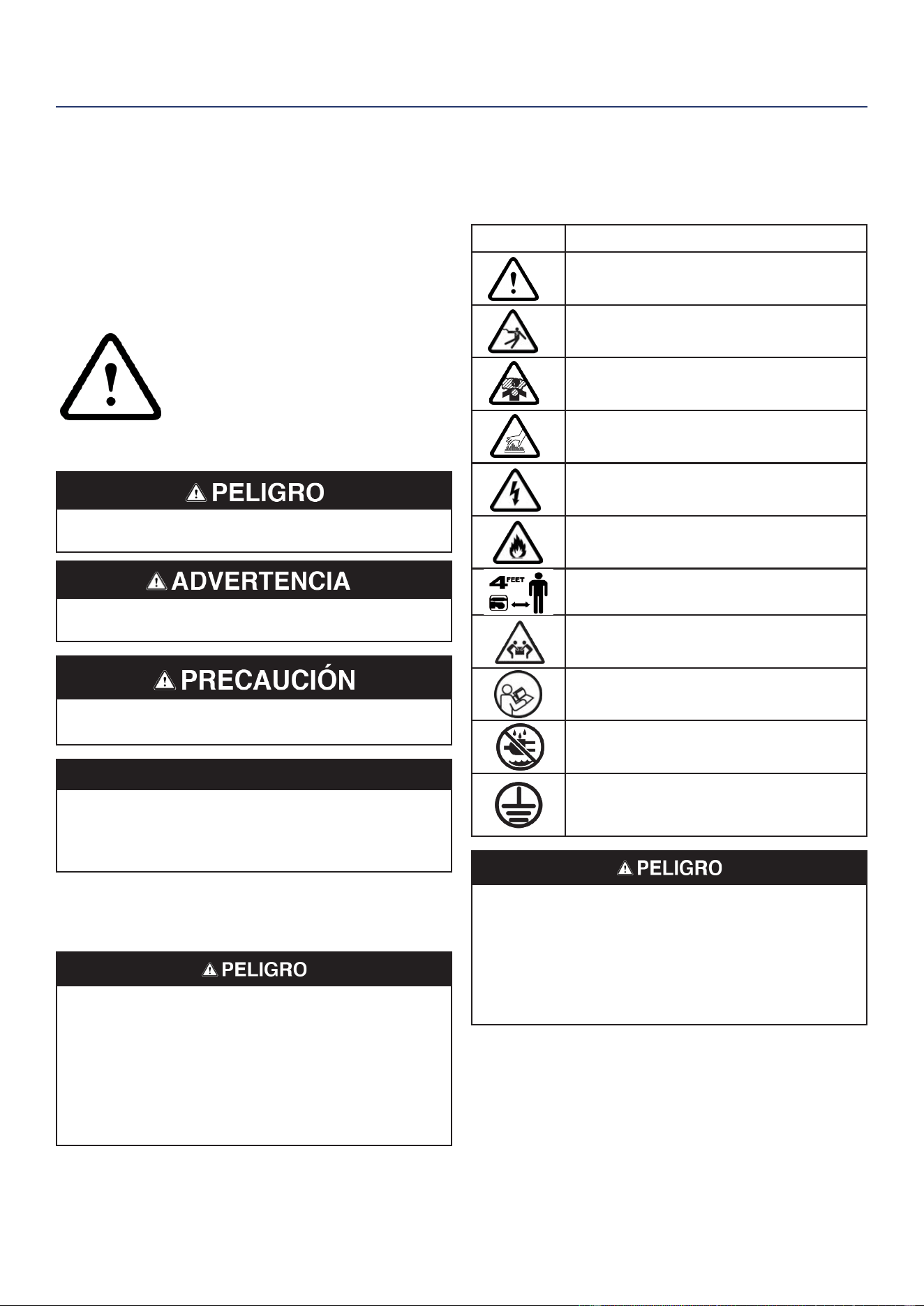
DEFINICIONES DE SEGURIDAD
Las palabras PELIGRO, ADVERTENCIA, PRECAUCIÓN
y AVISO se utilizan en este manual para resaltar
información importante. Asegúrese de que todos los que
operan, realizan mantenimiento o se encuentran cerca del
generador conozcan el signicado de esta información de
seguridad.
Aparece este símbolo de alerta de
seguridad con la mayoría de las
declaraciones de seguridad. Eso
signica atención, mantente alerta, tu
la seguridad está involucrada! Por
favor lea y Cumplir con el mensaje
que sigue el símbolo de alertas de
seguridad.
Indica una situación peligrosa que, si no se evita,
provocará la muerte o lesiones graves.
Indica una situación peligrosa que, si no se evita,
podría provocar la muerte o lesiones graves.
Indica una situación peligrosa que, si no se evita,
podría provocar lesiones leves o moderadas.
AVISO
Indica una situación que puede causar daños
al generador, propiedad personal y / o el medio
ambiente, o hacer que el equipo funcione
incorrectamente.
Nota: Indica un procedimiento, práctica o condición que
se debe seguir para que el generador funcione de
la manera prevista.
Riesgo de incendio y electrocución. No lo conecte
al sistema eléctrico de un edicio a menos que el
generador y el interruptor de transferencia se hayan
instalado correctamente y la salida eléctrica haya sido
vericada por un electricista calicado. La conexión
debe aislar la energía del generador de la energía de la
red pública y debe cumplir con todas las leyes y códigos
eléctricos aplicables.
SÍMBOLOS DE SEGURIDAD Y
SIGNIFICADO
Siga toda la información de seguridad contenida en este
manual y en el generador.
Símbolo Descripción
Símbolo de alerta de seguridad
Riesgo de electrocución
Peligro de asxia
Peligro de quemaduras. No toque
supercies calientes.
Peligro de descarga eléctrica
Peligro de incendio
Mantenga una distancia segura
Peligro de levantamiento
Leer las instrucciones del fabricante
No operar en condiciones de humedad
Suelo. Consulte con un electricista para
determinar los requisitos de conexión a
tierra antes de la operación.
Riesgo de electrocución. Nunca use el generador en un
lugar mojado o húmedo. Nunca exponga el generador
a la lluvia, nieve, rocío de agua o agua estancada
mientras esté en uso. Proteja el generador de todas
las condiciones climáticas peligrosas. La humedad
o el hielo pueden provocar un cortocircuito u otro mal
funcionamiento en el circuito eléctrico.
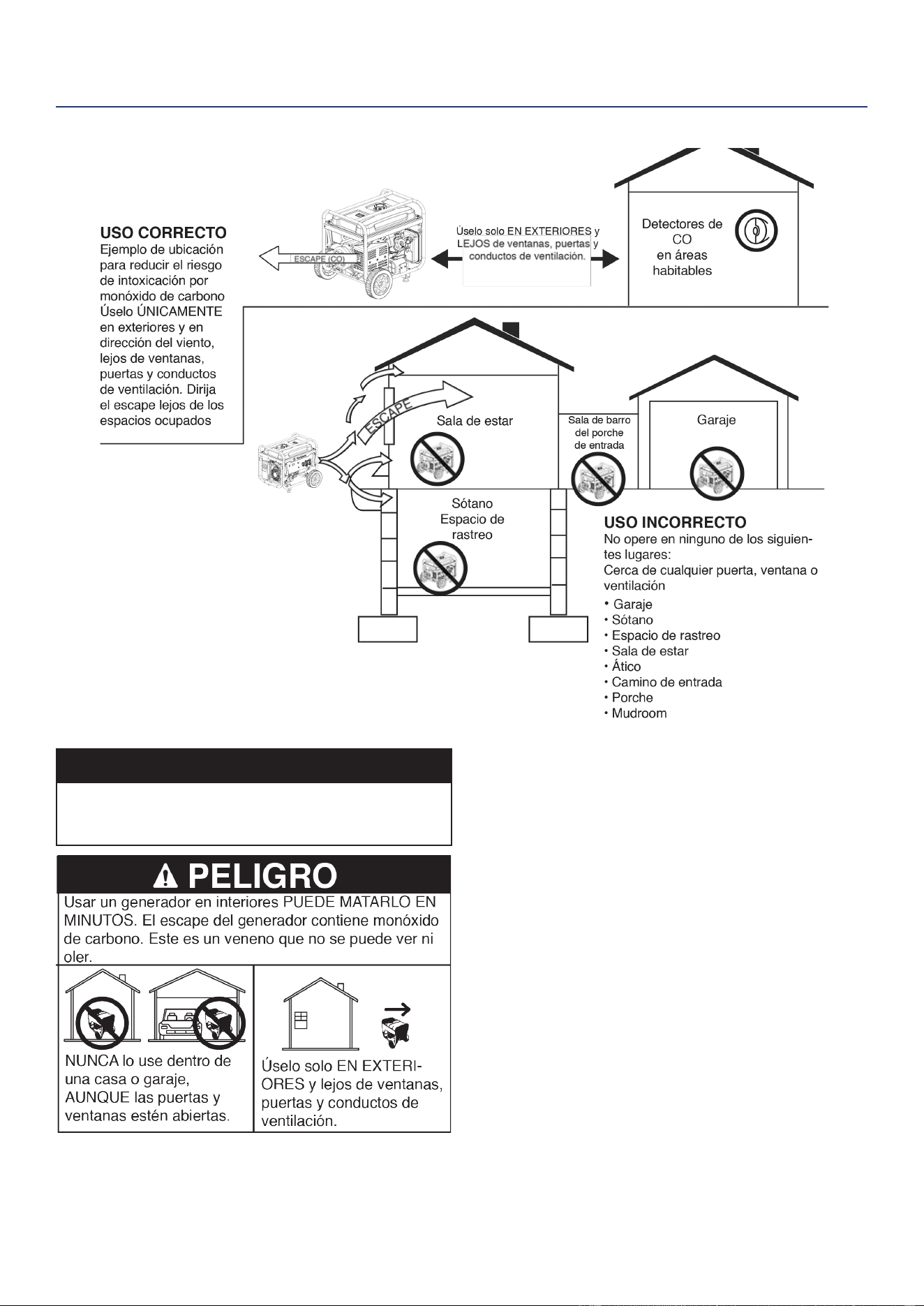
34 | Westinghouse Outdoor Power Equipment, LLC
LAS INSTRUCCIONES DE SEGURIDAD
AVISO
Instale detectores de monóxido de carbono a batería o
detectores de monóxido de carbono enchufables con
respaldo de batería en las áreas habitables.
PRECAUCIONES GENERALES DE
SEGURIDAD
• Nunca use el generador para alimentar equipos de
apoyo médico.
• No opere el generador cuando esté cansado o bajo la
inuencia de drogas, alcohol o medicamentos.
• No use el generador con cables eléctricos gastados,
deshilachados, desnudos o dañados.
• Todas las herramientas y artefactos eléctricos
operados con este generador deben estar debidamente
conectados a tierra mediante el uso de un tercer cable
o tener doble aislamiento.
• Cuando este generador se utiliza para suministrar
un sistema de cableado de un edicio, un electricista
calicado debe instalar el generador y conectarlo a un
interruptor de transferencia como un sistema derivado
por separado de acuerdo con NFPA 70, Código
Eléctrico Nacional.
• Si comienza a sentirse enfermo, mareado o débil
mientras usa el generador, muévase al aire fresco
INMEDIATAMENTE. Consulte a un médico, ya que
puede sufrir una intoxicación por monóxido de carbono.
LA SEGURIDAD

Westinghouse Outdoor Power Equipment, LLC | 35
• Úselo solo EN EXTERIORES y lejos de ventanas,
puertas y conductos de ventilación según lo
recomendado por los Centros para el Control y la
Prevención de Enfermedades del Departamento
de Salud y Servicios Humanos de EE. UU. Su casa
especíca y / o las condiciones del viento pueden
requerir una distancia adicional.
• Durante la operación y almacenamiento, mantenga al
menos 5 pies de espacio libre en todos los lados del
generador, incluido el techo. Deje que el generador se
enfríe un mínimo de 30 minutos antes de almacenarlo.
El calor creado por el silenciador y los gases de escape
puede ser lo sucientemente caliente como para
causar quemaduras graves y / o encender objetos
combustibles.
• No toque el silenciador ni el motor. Están muy
CALIENTES y causarán quemaduras graves. No
coloque partes del cuerpo ni ningún material inamable
o combustible en el camino directo del escape.
• Siempre retire cualquier herramienta u otro equipo de
servicio utilizado durante el mantenimiento lejos del
generador antes de operar.
• Evite el contacto de la piel con aceite de motor o
gasolina. Use ropa y equipo de protección. Lave toda
la piel expuesta con agua y jabón.
• Un interruptor de transferencia debe ser instalado por
un electricista autorizado y aprobado por la autoridad
competente. La instalación debe cumplir con todas las
leyes y códigos eléctricos aplicables.
SEGURIDAD DEL COMBUSTIBLE
• Almacene el combustible en un recipiente aprobado
para gasolina.
• No fume al llenar el generador con gasolina.
• No permita que el tanque de gasolina del generador se
desborde al llenarlo.
• Apague el motor y déjelo enfriar durante cinco minutos
antes de agregar gasolina o aceite al generador.
• Nunca quite la tapa de combustible cuando el
generador esté funcionando. Apague el motor y deje
que la unidad se enfríe por lo menos cinco minutos.
Retire la tapa de combustible lentamente para liberar
la presión, evitar que el combustible se escape por
la tapa y evitar que el calor del silenciador encienda
los vapores de combustible. Apriete bien la tapa de
combustible después de repostar.
• Limpie el combustible derramado de la unidad.
• Nunca intente quemar el combustible derramado.
• Nunca llene demasiado el tanque de combustible.
Deje espacio para que el combustible se expanda.
El llenado excesivo del tanque de combustible puede
provocar un desbordamiento repentino de gasolina y
provocar que la gasolina derramada entre en contacto
con supercies CALIENTES.
• El combustible derramado puede arder. Si se
derrama combustible sobre el generador, limpie
cualquier derrame inmediatamente. Deseche el trapo
correctamente. Deje que el área de combustible
derramado se seque antes de operar el generador.
• Use protección para los ojos mientras reposta.
• Nunca use gasolina como agente de limpieza.
• Almacene cualquier recipiente que contenga gasolina
en un área bien ventilada, lejos de cualquier combustible
o fuente de ignición.
GASOLINA Y VAPOR DE GASOLINA (GAS)
Riesgo de incendio y explosión. La gasolina es altamente
explosiva e inamable y puede causar quemaduras
graves o la muerte.
• En caso de un incendio de gas, no intente apagar la
llama si la válvula de combustible está en la posición
de gas. La introducción de un extintor en un generador
con una válvula de combustible abierta podría crear un
peligro de explosión. El gas tiene un olor distintivo, esto
ayudará a detectar posibles fugas rápidamente.
• Los vapores de gas pueden provocar un incendio si se
encienden.
• La gasolina irrita la piel y debe limpiarse inmediatamente
si entra en contacto con la piel.
Al arrancar el generador:
• Asegúrese de que la tapa de combustible, el ltro de
aire, la bujía, las líneas de combustible y el sistema de
escape estén colocados correctamente.
• Si derrama gasolina en el tanque, deje que se evapore
completamente antes de operar.
Al transportar o reparar el generador:
• Desconecte el cable de la bujía para evitar un arranque
accidental.
Al almacenar el generador:
• Almacene lejos de chispas, llamas abiertas, luces
piloto, calor y otras fuentes de ignición.
LA SEGURIDAD
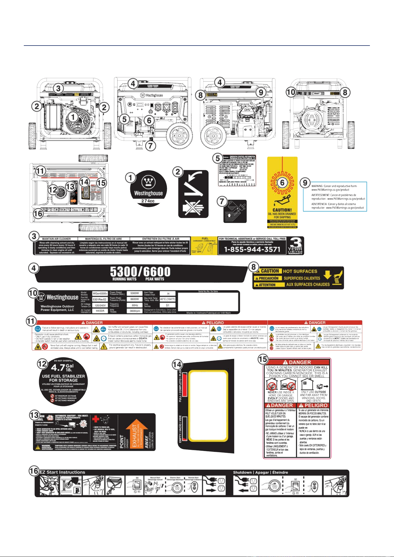
36 | Westinghouse Outdoor Power Equipment, LLC
CALCOMANÍAS DE SEGURIDAD
LA SEGURIDAD
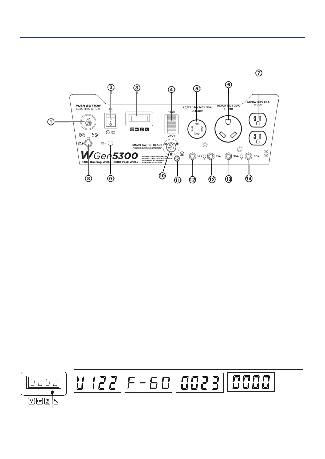
Westinghouse Outdoor Power Equipment, LLC | 37
COMPONENTES
COMPONENTES DEL PANEL DE CONTROL
COMPONENTES
1. Botón de arranque / parada: presione una vez
para arrancar el motor automáticamente. Presione
de nuevo para detener el motor.
2. Interruptor de batería: enciende y apaga la batería.
Debe estar ENCENDIDO antes del arranque eléctrico
o remoto.
3. Centro de datos: alterne para mostrar voltaje,
frecuencia, contador de horas total y temporizador
de funcionamiento / mantenimiento.
4. Interruptor selector de voltaje: seleccione 120
voltios o 240 voltios. Apague el generador antes de
cambiar los voltajes.
5. Receptáculo con cierre giratorio NEMA L14-
30R de 120/240 voltios CA, 30 amperios: el
receptáculo puede suministrar un máximo de 30
amperios.
6. Receptáculo NEMA TT-30R de 120 voltios CA,
30 amperios: el receptáculo puede suministrar un
máximo de 30 amperios.
7. Receptáculos NEMA 5-20R dúplex de 120
voltios CA, 20 amperios: los receptáculos pueden
suministrar un máximo de 20 amperios.
8. Puerto de carga de la batería: se utiliza para cargar
la batería con el cargador de batería incluido.
9. Indicador de batería: indica que la energía está
encendida. La luz permanecerá encendida mientras
la unidad esté encendida.
10. Salida de interruptor inteligente: conecta
el interruptor Westinghouse ST (se vende por
separado) al panel de control.
11. Terminal de tierra: El terminal de tierra se utiliza
para conectar a tierra externamente el generador.
12. Disyuntores de 22 amperios: cada disyuntor
limita la corriente que se puede suministrar a
través de cada tramo de 120 voltios en L14-30R a
22 amperios.
13. Disyuntor de CA de 30 amperios: El disyuntor
limita la corriente que se puede suministrar a través
del receptáculo TT-30R a 30 amperios.
14. Disyuntor de 20 amperios de CA: el disyuntor
limita la corriente que se puede suministrar a través
de los receptáculos NEMA 5-20R a 20 amperios.
Visualización de datos
Frecuencia (Hz):
Muestra la frecuencia de
salida de potencia en
hercios
Voltaje:
Muestra la salida de
voltaje actual
Modo de botón
METER V-F-T
Tiempo de ejecución /
mantenimiento:
Muestra el tiempo de ejecución
actual. Se restablece a cero cuando
se apaga. Se muestra un recordatorio
de mantenimiento cuando es necesario.
Horas de vida:
Muestra las horas de
funcionamiento de la
vida útil
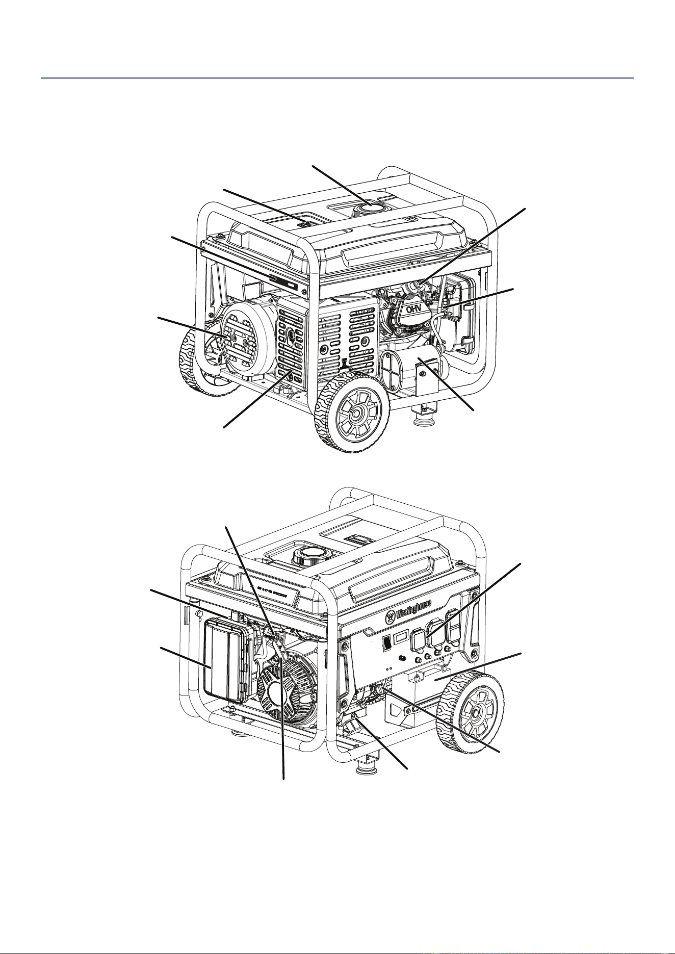
38 | Westinghouse Outdoor Power Equipment, LLC
COMPONENTES DEL GENERADOR
Tapa de combustible
Indicador de combustible
Silenciador / parachispas
Recipiente de carbono
Carburador
Tapa del alternador
Bujía
Número de serie
Perno de
drenaje de aceite
Varilla medidora de
aceite / boca de
llenado
Panel de control
Arrancador
de retroceso
Filtro de aire
Válvula del
tanque de combustible
Palanca del
estrangulador
Batería
COMPONENTES
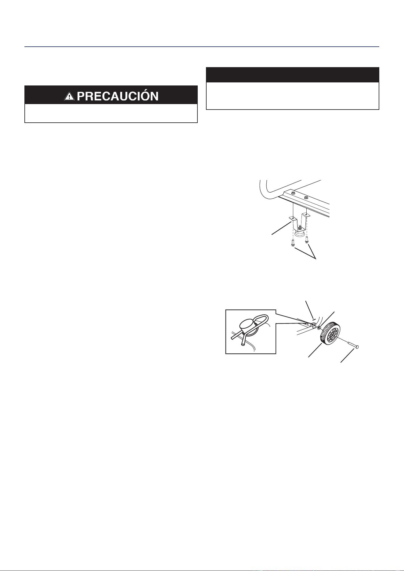
Westinghouse Outdoor Power Equipment, LLC | 39
MONTAJE
CONTENIDO DE LA CAJA
Peligro de peso. Siempre tenga ayuda cuando levante
el generador.
1. Abra la caja con cuidado.
2. Retire y deseche los materiales de embalaje.
3. Despliegue la parte superior de la bolsa de plástico que
encierra el generador.
4. Corte con cuidado las esquinas verticales de la caja
para acceder al generador.
5. Recicle o deseche los materiales de embalaje
correctamente.
CONTENIDO DE LA CAJA
• Manual de usuario
• Guía de inicio rápido
• Botella de aceite SAE 10W-30
• Llave de tubo para bujías
• Llave inglesa
• Cargador de batería
Articulo Cantidad
• Pie de montaje 2
• Perno de brida, M8 4
• Rueda 2
• Pasador del eje 2
• Lavadora 2
• Pasador de chaveta 2
Si falta alguna pieza, comuníquese con nuestro
equipo de servicio en [email protected] o llame
al 1-855-944-3571.
INSTALE PIES Y RUEDAS
AVISO
El ensamblaje del generador requerirá levantar la
unidad por un lado. Instale las patas de montaje y la
rueda antes de agregar combustible o aceite.
1. Coloque el generador sobre una supercie plana.
2. Incline el generador sobre un trozo de cartón u otro
material blando para proteger la pintura del marco y
evitar que el generador se deslice.
3. Con la llave incluida, instale los pies de montaje en el
marco como se muestra.
Pie de montaje
Tornillo, M8
4. Instale las ruedas como se muestra.
Pasador del eje
Rueda
Pasador de chaveta
Lavadora
Nota: Las ruedas solo están diseñadas para el transporte
manual. Las ruedas no son adecuadas para
remolcar el generador dentro o fuera de la carretera.
MONTAJE
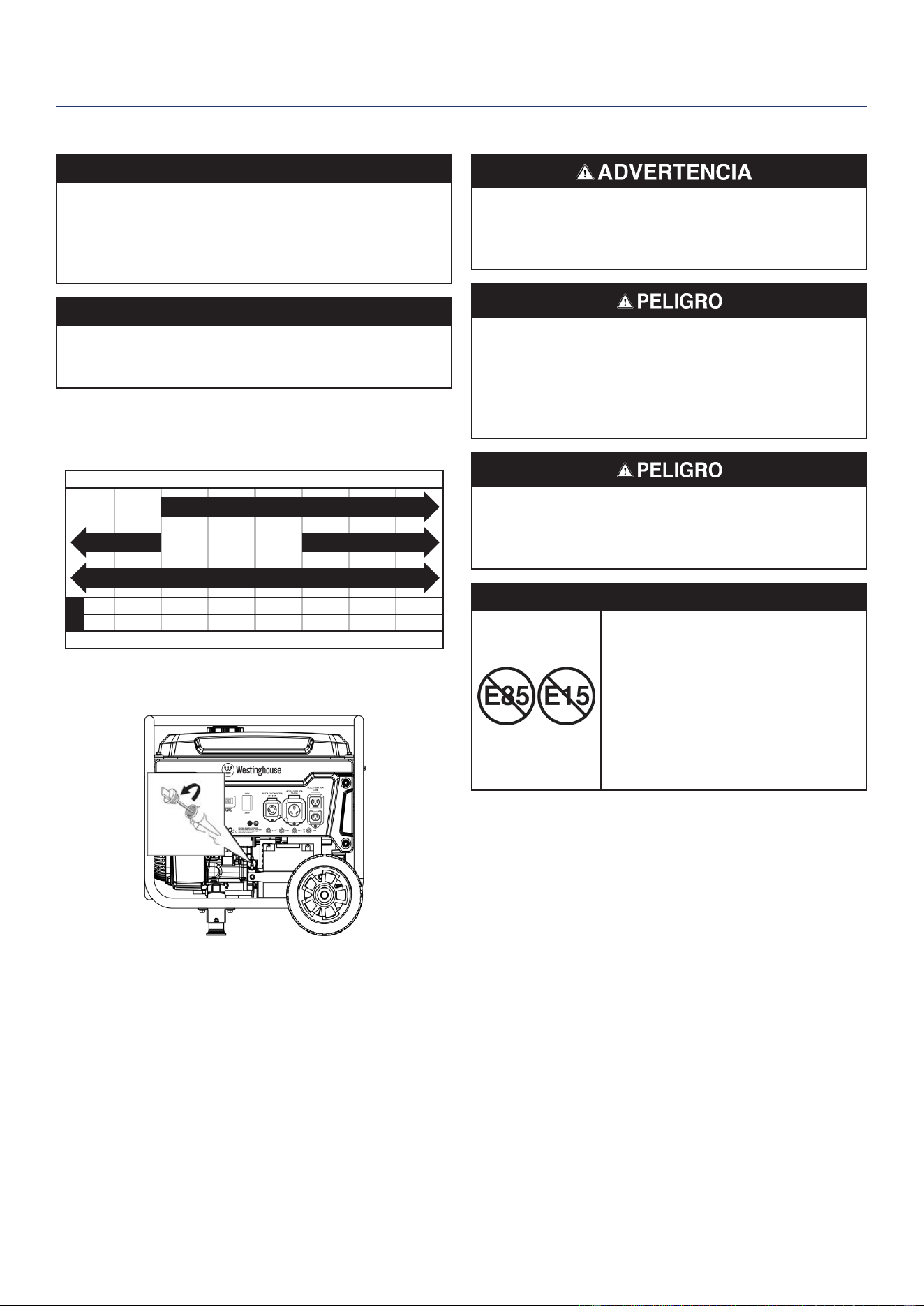
40 | Westinghouse Outdoor Power Equipment, LLC
MONTAJE
LLENADO DE ACEITE INICIAL
AVISO
ESTE GENERADOR SE HA ENVIADO SIN ACEITE. No
intente arrancar o arrancar el motor antes de que haya
recibido el servicio adecuado con el aceite recomendado.
No agregar aceite de motor antes de arrancar resultará
en daños graves al motor.
AVISO
El uso de aceite de 2 tiempos / ciclo u otros tipos de
aceite no aprobados puede causar daños graves al
motor que no están cubiertos por la garantía.
El tipo de aceite recomendado incluido para uso típico es
aceite de motor 10W-30. Si hace funcionar el generador
en temperaturas extremas, consulte la siguiente tabla.
-20 0 20 40 60
Temperatura ambiente
Tipo de aceite de motor recomendado
80 100 120
-28.9
°F
°C -17.8 -6.7 4.4 15.6 26.7 37.8 48.9
10W-30
5W-30 Synthetic
10W-405W-30
1. En una supercie nivelada, retire la varilla medidora de
aceite.
2. Con el embudo y el aceite suministrados, agregue
aceite en la boca de llenado de aceite.
Nota: Como el aceite residual de la fábrica puede
permanecer en el motor, agregue el aceite
gradualmente cerca del nal de la botella para
evitar sobrellenar el motor. Consulte Comprobación
del nivel de aceite del motor en la sección
Mantenimiento.
3. Limpiar la varilla de nivel de aceite. Reemplace la varilla
medidora de aceite y apriete a mano.
COMBUSTIBLE
Riesgo de incendio y explosión. Nunca use un
recipiente de gasolina, tanque de gasolina o cualquier
otro elemento de combustible que esté roto, cortado,
rasgado o dañado.
Riesgo de incendio y explosión. No llene demasiado
el tanque de combustible. Llene solo hasta el anillo de
llenado rojo ubicado en el ltro de malla de combustible
en el tanque. El sobrellenado puede hacer que el
combustible se derrame sobre el motor y cause un
riesgo de incendio o explosión.
Riesgo de incendio y explosión. Nunca reposte el
generador con el motor en marcha. Siempre apague
el motor y deje que el generador se enfríe durante dos
minutos antes de repostar.
AVISO
No utilice combustible E15 o E85
en este producto. La garantía no
cubre los daños al motor o al equipo
causados por combustible viejo o el
uso de combustibles no aprobados
(como mezclas de etanol E15 o
E85). Utilice únicamente gasolina sin
plomo que contenga hasta un 10%
de etanol.
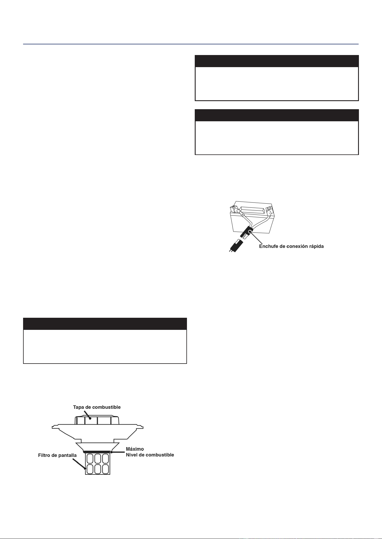
Westinghouse Outdoor Power Equipment, LLC | 41
MONTAJE
REQUISITOS DE COMBUSTIBLE
• Gasolina sin plomo, fresca y magra, de 87 a 93 octanos.
• Se acepta hasta un 10% de etanol (gasohol) (cuando
esté disponible; se recomienda combustible sin etanol).
• NO use E85 o E15.
• NO use una mezcla de gasóleo.
• NO modique el motor para que funcione con
combustibles alternativos.
• NO cargue combustible en interiores.
• NO cree una chispa o llama mientras reposta.
USANDO ESTABILIZADOR DE COMBUSTIBLE
Agregar un estabilizador de combustible (no incluido)
extiende la vida útil del combustible y ayuda a prevenir la
formación de depósitos que pueden obstruir el sistema de
combustible. Siga las instrucciones de uso del fabricante.
Siempre mezcle la cantidad correcta de estabilizador de
combustible con gasolina en un recipiente de gasolina
aprobado antes de cargar combustible al generador. Haga
funcionar el generador durante cinco minutos para permitir
que el estabilizador trate todo el sistema de combustible.
LLENADO DEL TANQUE DE COMBUSTIBLE
1. Apague el generador y deje que se enfríe durante un
mínimo de dos minutos antes de cargar combustible.
2. Coloque el generador en un terreno nivelado en un área
bien ventilada.
3. Limpie el área alrededor de la tapa de combustible y
retire la tapa lentamente.
AVISO
Llene el tanque únicamente con un recipiente de
gasolina aprobado. Asegúrese de que el recipiente de
gasolina esté limpio por dentro y en buenas condiciones
para evitar la contaminación del sistema de combustible.
4. Agregue lentamente el combustible recomendado. No
llene demasiado. Llene solo hasta el anillo de llenado
máximo rojo en el ltro de malla de combustible visible
en el cuello de llenado.
5. Instale la tapa de combustible. Apriete hasta que se
escuche un clic.
AVISO
El combustible puede dañar la pintura y el plástico.
Tenga cuidado al llenar el tanque de combustible. Los
daños causados por el combustible derramado no están
cubiertos por la garantía.
AVISO
Limpie los residuos del ltro de malla de combustible
antes y después de cada repostaje. Quite el ltro de
malla de combustible comprimiéndolo ligeramente
mientras lo saca del tanque de combustible.
CONECTAR LA BATERÍA
Un enchufe de batería de conexión rápida está preinstalado
en la batería. Retire la atadura de cables que sujeta los
enchufes y luego presione rmemente para conectarlos.
Nota: El generador está equipado con una función de carga
de batería. Una vez que el motor está funcionando,
una pequeña carga recargará lentamente la batería.
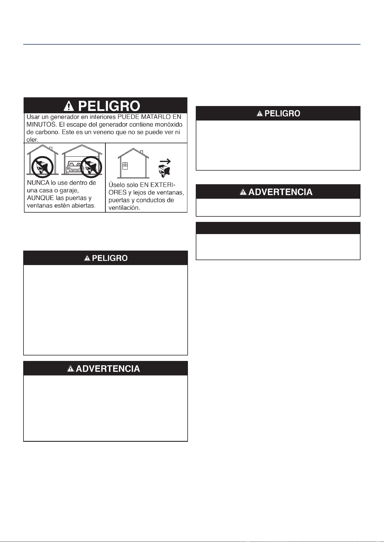
42 | Westinghouse Outdoor Power Equipment, LLC
OPERACIÓN
CUBICACIÓN DEL GENERADOR
Lea y comprenda toda la información de seguridad antes
de encender el generador.
NUNCA opere el generador dentro de un edicio, incluidos
garajes, sótanos, espacios de acceso, cobertizos,
cerramientos o compartimentos, incluido el compartimiento
del generador de un vehículo recreativo.
Riesgo de electrocución. Nunca use el generador en un
lugar mojado o húmedo. Nunca exponga el generador
a la lluvia, nieve, rocío de agua o agua estancada
mientras esté en uso. Proteja el generador de todas
las condiciones climáticas peligrosas. La humedad
o el hielo pueden provocar un cortocircuito u otro
mal funcionamiento en el circuito eléctrico. El uso de
un generador o aparato eléctrico en condiciones de
humedad, como lluvia o nieve, o cerca de una piscina
o sistema de rociadores, o cuando sus manos están
mojadas, puede resultar en electrocución.
Peligro de incendio. Utilice el generador únicamente
sobre una supercie sólida y nivelada. Operar el
generador en una supercie con material suelto,
como arena o recortes de césped, puede hacer que el
generador ingiera desechos que podrían bloquear las
rejillas de ventilación o el sistema de admisión de aire.
Deje que el generador se enfríe durante 30 minutos
antes de transportarlo o almacenarlo.
TEl generador debe estar en una supercie plana y
nivelada en todo momento (incluso cuando no esté en
funcionamiento). El generador debe tener al menos 5 pies
(1,5 m) de espacio libre de todo material combustible.
No opere el generador en la parte trasera de un SUV,
caravana, remolque, caja de camión (regular, plana o
de otro tipo), debajo de escaleras, cerca de paredes
o edicios, o en cualquier otro lugar que no permita el
enfriamiento adecuado del generador y / o silenciador. NO
contenga generadores durante el funcionamiento.
Peligro de asxia. Coloque el generador en un área bien
ventilada. NO coloque el generador cerca de conductos
de ventilación o entradas donde los gases de escape
puedan entrar en espacios ocupados o connados.
Considere cuidadosamente las corrientes de aire y
viento cuando coloque el generador.
TOMA DE TIERRA
Peligro de choque. No conectar a tierra correctamente
el generador puede provocar una descarga eléctrica.
AVISO
Utilice únicamente cables de extensión, herramientas y
electrodomésticos de 3 clavijas con conexión a tierra, o
herramientas y electrodomésticos con doble aislamiento.
El neutro del generador está otando. El terminal de
tierra del generador está conectado a la estructura
del generador, las partes metálicas no portadoras de
corriente del generador y los terminales de tierra de cada
receptáculo. El generador (devanado del estator) está
aislado del bastidor y de la clavija de tierra del receptáculo
de CA. Es posible que los dispositivos eléctricos que
requieren una conexión de clavija de toma a tierra no
funcionen correctamente.
Si este generador se usará solo con un cable y equipo
de enchufe conectados a los receptáculos montados en
el generador, el Código Eléctrico Nacional no requiere
que la unidad esté conectada a tierra. Sin embargo, otros
métodos de uso del generador pueden requerir conexión
a tierra para reducir el riesgo de descarga eléctrica o
electrocución.
Antes de usar la terminal de tierra, consulte a un electricista
calicado, inspector eléctrico o agencia local que tenga
jurisdicción sobre los códigos u ordenanzas locales que
se aplican al uso previsto del generador.
OPERACIÓN
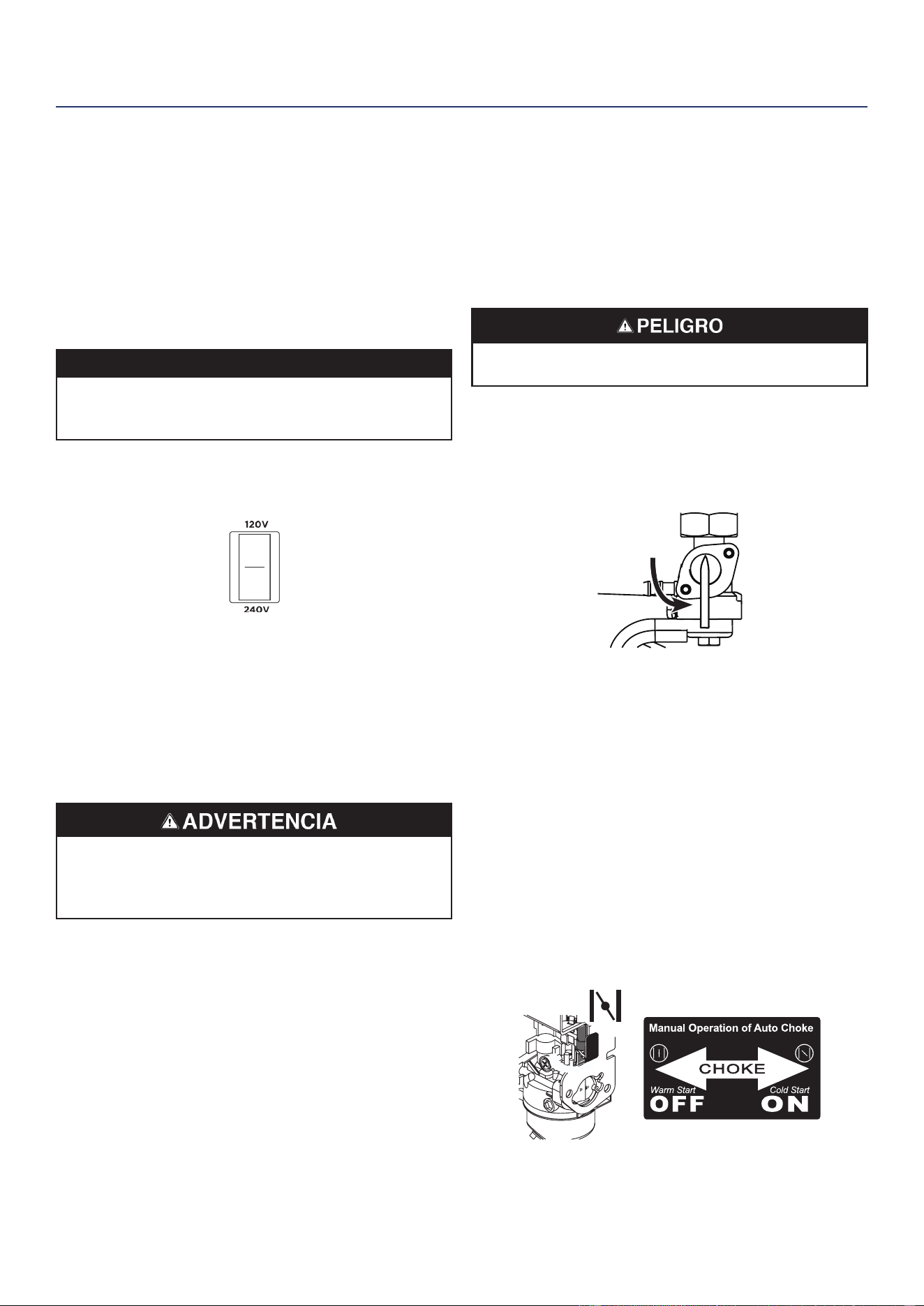
Westinghouse Outdoor Power Equipment, LLC | 43
OPERACIÓN A GRAN ALTITUD
LLa potencia del motor se reduce cuanto más alto se
opera sobre el nivel del mar. La producción se reducirá
aproximadamente un 3,5% por cada 1000 pies de aumento
de altitud desde el nivel del mar.
Se requiere un ajuste de altitud elevada para el funcionamiento
a altitudes superiores a los 2.000 pies (762 m). El
funcionamiento sin este ajuste provocará una disminución
del rendimiento, un mayor consumo de combustible y un
aumento de las emisiones.
AVISO
NO opere el generador en altitudes inferiores a 2.000
pies (762 m) con el kit de gran altitud instalado. Pueden
producirse daños en el motor.
Kit de carburador para gran altitud: Parte# 518965
INTERRUPTOR SELECTOR DE VOLTAJE
El interruptor selector de 120V / 240V, que brinda al
usuario la capacidad de duplicar el amperaje en el
generador para aplicaciones más exigentes. El selector
de voltaje cambia los devanados duales de 120 V CA del
generador para producir 120 V o 240 V. Si un aparato
de 240 V está conectado al receptáculo L14-30R de 4
clavijas, el interruptor debe estar en la posición “240 V”.
Los tomacorrientes de solo 120 V no emitirán energía
cuando el selector de voltaje esté en la posición de 240 V.
Solo cambie el interruptor selector de voltaje con el
generador apagado. No cambie el voltaje mientras
el generador está funcionando o alimentando
electrodomésticos.
PERÍODO DE RODAJE
Para un rodaje adecuado, no exceda el 50% de los ivajes
nominales. de funcionamiento (2650 vatios) durante las
primeras cinco horas de funcionamiento.
Varíe la carga ocasionalmente para permitir que los
devanados del estator se calienten y enfríen y ayuden a
asentar los anillos del pistón.
ANTES DE ARRANCAR EL GENERADOR
Comprueba eso:
• El generador se coloca en un lugar seguro y apropiado.
• El generador está sobre una supercie seca, plana y
nivelada.
• El motor está lleno de aceite.
• Todas las cargas están desconectadas.
Riesgo de incendio y explosión. NO mueva ni incline el
generador durante el funcionamiento.
ARRANCAR EL MOTOR
1. Verique que haya combustible en el tanque de gasolina.
2. Gire la válvula del tanque de combustible a la posición
ON.
ON
OFF
3. Empuje el interruptor de la batería a la posición ON.
4. Elija el método de inicio:
c. Arranque remoto: Mantenga presionado el botón
START en el llavero de arranque remoto durante un
segundo.
d. Arranque con botón pulsador: Mantenga pulsado
el botón ARRANQUE / PARO del motor durante dos
segundos.
e. Inicio de retroceso: Si es un arranque en frío,
cierre manualmente el estrangulador moviéndolo
hacia la derecha hacia la manija delantera del
generador.Sujete rmemente y tire lentamente de
la manija de retroceso hasta que sienta una mayor
resistencia, luego tire rápidamente.
OPERACIÓN

44 | Westinghouse Outdoor Power Equipment, LLC
PARAR EL MOTOR
1. Apague y desenchufe todas las cargas eléctricas
conectadas.
IMPORTANTE: Nunca arranque ni detenga el generador
con dispositivos eléctricos conectados.
2. Deje que el generador funcione sin carga durante varios
minutos para estabilizar las temperaturas internas del
motor.
3. Mantenga presionado el botón START / STOP durante
un segundo o presione STOP en el llavero de inicio
remoto durante un segundo.
Nota: Alternativamente, si el generador se usa con
poca frecuencia, gire la válvula del tanque de
combustible a la posición de APAGADO para limitar
el combustible residual que queda en la taza del
otador del carburador. El motor se detendrá
cuando se agote el combustible en el carburador y
la línea de combustible..
4. Empuje el interruptor de la batería a la posición de
APAGADO.
FRECUENCIA DE USO
Si el generador se usará de manera poco frecuente
o intermitente (más de un mes antes del próximo uso),
consulte las secciones de Mantenimiento y almacenamiento
de la batería de este manual para obtener información
sobre la carga de la batería y el deterioro del combustible.
DISYUNTORES DE CA
Los disyuntores se apagarán automáticamente si hay un
cortocircuito o una sobrecarga signicativa del generador
en cada receptáculo.
Si un disyuntor de CA se APAGA automáticamente,
verique que el aparato esté funcionando correctamente y
que no exceda la capacidad de carga nominal del circuito
antes de reiniciar el disyuntor de CA.
CAPACIDAD DEL GENERADOR
AVISO
No sobrecargue la capacidad del generador. Exceder
la capacidad de vataje/amperaje del generador puede
dañar el generador y/o los dispositivos eléctricos
conectados a él.
Asegúrese de que el generador pueda suministrar
sucientes vatios continuos (en funcionamiento) y
de sobretensión (arranque) para los elementos que
alimentará al mismo tiempo.
Se deben considerar los requisitos de potencia total (voltios
x amperios = vatios) de todos los aparatos conectados.
Los fabricantes de electrodomésticos y herramientas
eléctricas suelen incluir información de clasicación cerca
del modelo o número de serie.
Para determinar los requisitos de energía:
1. Seleccione los elementos que alimentará al mismo
tiempo.
2. Sume los vatios continuos (en funcionamiento) de estos
artículos. Esta es la cantidad de energía que debe
producir el generador para mantener los elementos
en funcionamiento. Consulte la tabla de referencia de
potencia en la página siguiente.
3. Calcule cuántos vatios de sobretensión (arranque)
necesitará. El vataje de sobretensión es la breve ráfaga
de energía necesaria para arrancar herramientas o
aparatos accionados por motor eléctrico, como una
sierra circular o un refrigerador. Debido a que no todos
los motores arrancan al mismo tiempo, los vatios de
sobretensión totales se pueden estimar agregando
solo los elementos con los vatios de sobretensión
adicionales más altos al total de vatios nominales del
paso 2.
Ejemplo:
Herramienta o aparato
Ejecución
de Watts *
Watts de
arranque*
TV (pantalla plana) 120 235
Refrigerador RV 180 600
Radio 200 0
Ligera (75 vatios) 300 0
Cafetera 600 0
Totales 1400
Vatios totales en funcionamiento 1400
Watts iniciales más altos + 600
Total de vatios iniciales necesarios 2000
* Las potencias indicadas son aproximadas. Verique la potencia real.
OPERACIÓN
Westinghouse Outdoor Power Equipment, LLC | 45
OPERACIÓN
GESTIÓN DE ENERGÍA
Para prolongar la vida útil del generador y los dispositivos
conectados, tenga cuidado al agregar cargas eléctricas al
generador. No debe haber nada conectado a las salidas del
generador antes de arrancar el motor. La forma correcta y
segura de administrar la energía del generador es agregar
cargas secuencialmente de la siguiente manera:
1. Sin nada conectado al generador, arranque el motor
como se describe en este manual.
2. Enchufe y encienda la primera carga, preferiblemente
la carga más grande que tenga.
3. Permita que la salida del generador se estabilice
(el motor funciona sin problemas y el dispositivo
conectado funciona correctamente).
4. Enchufe y encienda la siguiente carga.
5. Nuevamente, permita que el generador se estabilice.
6. Repita los pasos 4 y 5 para cada carga adicional.
Referencia de potencia
Herramienta o aparato
Watts de
funcionamiento
estimados *
Watts
iniciales
estimados *
Luces incandescentes (4
cantidades x 75 vatios)
300 0
TV (pantalla plana) 120 235
Bomba de sumidero
(1/3 hp)
800 1300
Refrigerador o congelador 700 2200
Bomba de pozo (1/3 hp) 1000 2000
Radio 200 0
Taladro (3/8 “, 4 amperios) 440 600
Sierra circular
(Servicio pesado, 7-1 / 4 “)
1400 2300
Sierra de inglete (10 “) 1800 1800
Sierra de mesa (10 “) 2000 2000
* Las potencias indicadas son aproximadas. Verique la potencia real.
CABLES DE EXTENSIÓN
Peligro de asxia. Los cables de extensión que llegan
directamente a la casa aumentan el riesgo de intoxicación
por monóxido de carbono a través de las aberturas. Si
se utiliza un cable de extensión que llega directamente
a su casa para alimentar elementos de interior, existe el
riesgo de intoxicación por monóxido de carbono para las
personas dentro de la casa. Utilice siempre detectores
de monóxido de carbono a batería que cumplan con los
estándares de seguridad UL 2034 actuales cuando haga
funcionar el generador. Compruebe periódicamente la
batería de los detectores.
Peligro de asxia. Cuando opere el generador con
cables de extensión, asegúrese de que el generador
esté ubicado en un área abierta al aire libre, al menos a
20 pies (6 m) de los espacios ocupados con el escape
apuntando hacia afuera.
Riesgo de incendio y electrocución. Nunca use cables de
extensión gastados o dañados. Los cables de extensión
dañados o sobrecargados podrían sobrecalentarse,
formarse un arco y quemarse y provocar la muerte o
lesiones graves.
Antes de conectar un aparato de CA o un cable de
alimentación al generador:
• Use cables de extensión, herramientas y
electrodomésticos de tres clavijas con conexión a
tierra, o herramientas y electrodomésticos con doble
aislamiento.
• Asegúrese de que la herramienta o el aparato estén
en buenas condiciones de funcionamiento. Los
electrodomésticos o cables de alimentación defectuosos
pueden crear una posible descarga eléctrica.
• Asegúrese de que la clasicación eléctrica de la
herramienta o aparato no exceda la potencia nominal
del generador o del receptáculo que se está utilizando.
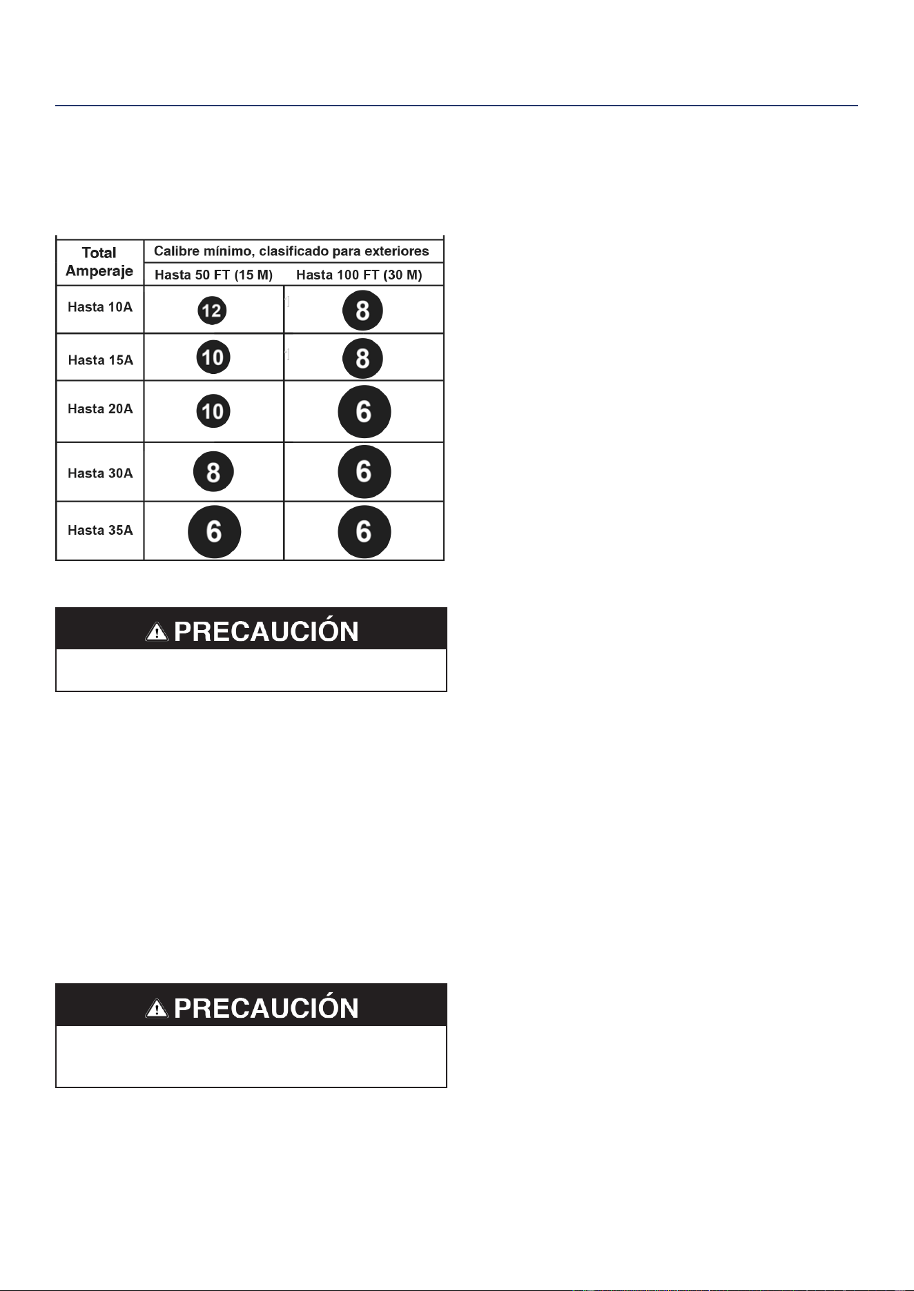
46 | Westinghouse Outdoor Power Equipment, LLC
TAMAÑO DEL CABLE DE EXTENSIÓN
Utilice únicamente cables de extensión de 3 clavijas con
conexión a tierra marcados para uso en exteriores que
estén clasicados para la carga eléctrica.
TRANSPORTE
Peligro de peso. Siempre tenga ayuda cuando levante
el generador.
• Deje que el generador se enfríe un mínimo de 30
minutos antes de transportarlo.
• Reemplace todas las cubiertas protectoras en el panel
de control del generador.
• Utilice únicamente el bastidor jo del generador para
levantar la unidad o sujetar cualquier restricción de
carga, como cuerdas o correas de amarre. No intente
levantar o asegurar el generador sujetándose a ninguno
de sus otros componentes.
• una sola persona. Utilice la manija únicamente cuando
el generador esté APAGADO, parado y apoyado sobre
una supercie horizontal. No use la manija para levantar
el generador completamente del suelo, remolcarlo o
ponerlo.
Peligro de incendio. No apague completamente el
generador. Se pueden producir fugas de combustible o
aceite y se pueden producir daños en el generador.
OPERACIÓN
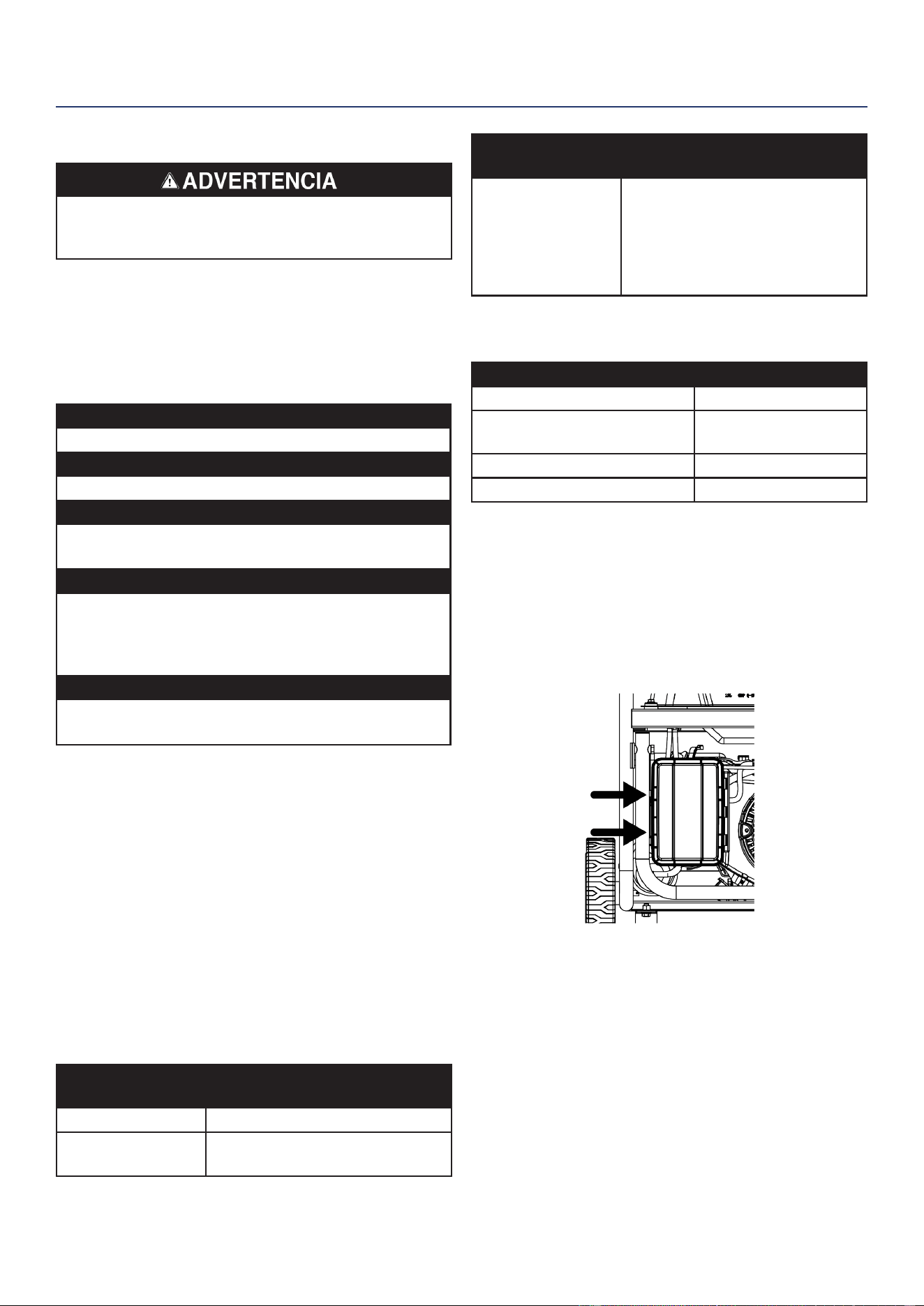
Westinghouse Outdoor Power Equipment, LLC | 47
MANTENIMIENTO
Arranque accidental. Desconecte la funda de la bujía de
la bujía y desconecte las bujías de conexión rápida de la
batería cuando realice el mantenimiento del generador.
PROGRAMA DE MANTENIMIENTO
El mantenimiento regular mejorará el rendimiento y
extenderá la vida útil del generador. Siga los intervalos
horarios o de calendario, lo que ocurra primero. Se
requiere un servicio más frecuente cuando se opera en
condiciones adversas como se indica a continuación.
Antes de cada uso
Revise el aceite del motor
Después de las primeras 25 horas o el primer mes
Cambia el aceite del motor
Después de 50 horas o cada 6 meses
Cambiar el aceite del motor
1
Filtro de aire limpio
2
Después de 100 horas o cada 6 meses
Inspeccione / limpie el parachispas
Inspeccione / limpie la bujía
Mantenimiento de la válvula de combustible
Inspeccione / ajuste el juego de válvulas
3
Después de 300 horas o cada año
Reemplace la bujía
Reemplazar ltro de aire
1
Cambie el aceite cada mes cuando opere bajo carga
pesada o en altas temperaturas.
2
Limpie con más frecuencia en condiciones de
suciedad o polvo. Reemplace el ltro de aire si no se
puede limpiar adecuadamente.
3
Recomiende que el servicio lo realice un distribuidor
de servicio autorizado de Westinghouse.
RECORDATORIOS DE MANTENIMIENTO
Los códigos de recordatorio de mantenimiento se
mostrarán en la pantalla de datos según las horas de
vida útil de la unidad. Los códigos de mantenimiento se
mostrarán hasta que se apague la unidad. Consulte la
sección Mantenimiento para conocer los procedimientos
especícos.
Código de
mantenimiento
Mantenimiento requerido
P25 Cambia el aceite del motor
P50
• Cambia el aceite del motor
• Filtro de aire limpio
Código de
mantenimiento
Mantenimiento requerido
P100
• Cambia el aceite del motor
• Filtro de aire limpio
• Mantenimiento de la válvula
de combustible
• Inspeccione / ajuste la holgura
de la válvula
PIEZAS DE REPUESTO PARA
MANTENIMIENTO
Descripción Número de pieza
Filtro de aire 5941
Arandela de presión del tapón
de drenaje de aceite
94007
Supresor de chispas 6790
Bujía 97108 (F7TC)
MANTENIMIENTO DEL FILTRO DE AIRE
El ltro de aire debe limpiarse después de cada 50 horas
de uso o cada seis meses (la frecuencia debe aumentarse
si el generador se opera en un ambiente polvoriento).
1. Coloque el generador en una supercie nivelada y deje
que el motor se enfríe durante varios minutos.
2. Suelte los clips y retire la tapa del ltro de aire.
3. Limpiar el ltro de aire con aire comprimido. Reemplácelo
si está dañado.
MANTENIMIENTO
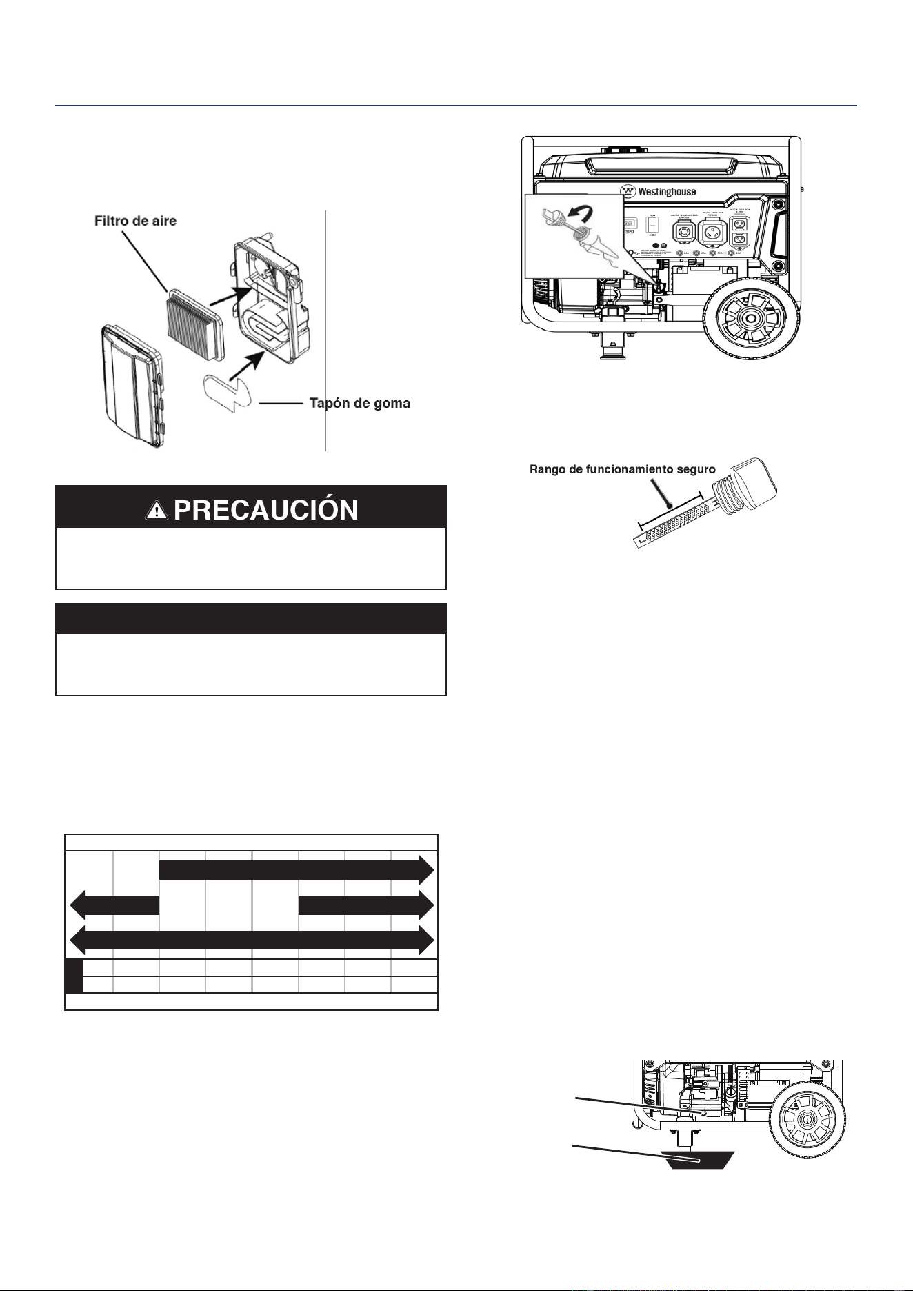
48 | Westinghouse Outdoor Power Equipment, LLC
4. Asegúrese de que el ltro de aire y la tapa de goma
estén instalados correctamente. Instale la cubierta
del ltro de aire y fíjela en su lugar con los clips de la
cubierta.
DEL MOTOR
Evite el contacto de la piel con el aceite del motor. Use
ropa y equipo de protección. Lave toda la piel expuesta
con agua y jabón.
AVISO
Utilice siempre el aceite de motor especicado. No
utilizar el aceite de motor especicado puede provocar
un desgaste acelerado y / o acortar la vida útil del motor.
Cuando utilice el generador en condiciones extremas,
sucias, polvorientas o en un clima extremadamente
caluroso, cambie el aceite con más frecuencia.
La temperatura ambiente del aire afectará el rendimiento
del aceite del motor. Cambie el tipo de aceite de motor
utilizado según las condiciones climáticas.
-20 0 20 40 60
Temperatura ambiente
Tipo de aceite de motor recomendado
80 100 120
-28.9
°F
°C -17.8 -6.7 4.4 15.6 26.7 37.8 48.9
10W-30
5W-30 Synthetic
10W-405W-30
Compruebe el nivel de aceite del motor antes de cada uso
o cada 8 horas de funcionamiento.
1. Coloque el generador en una supercie nivelada y deje
que el motor se enfríe durante varios minutos.
2. Con un trapo húmedo, limpie alrededor de la varilla
medidora de aceite.
3. Retire la varilla medidora de aceite y límpiela.
4. Inserte la varilla en la boca de llenado de aceite sin
enroscarla. Retire la varilla y verique que el nivel de
aceite esté dentro del rango de funcionamiento seguro
entre las marcas bajo (L) y alto (H) en la varilla.
5. Si es bajo, agregue gradualmente el aceite de motor
recomendado y vuelva a vericar hasta que el nivel esté
entre las marcas L y H de la varilla de medición. No
llene demasiado. Si sobrepasa la marca H en la varilla,
drene el aceite para reducir el nivel de aceite a la marca
de lleno.
6. Reemplace la varilla medidora de aceite y apriete a
mano.
CAMBIO DE ACEITE DEL MOTOR
Cuando utilice el generador en condiciones sucias,
polvorientas o en un clima extremadamente caluroso,
cambie el aceite con más frecuencia. Cambie el aceite
mientras el motor aún está caliente por la operación.
1. Coloque el generador en una supercie nivelada y deje
que el motor se enfríe durante varios minutos.
2. Con un trapo húmedo, limpie alrededor de la varilla
medidora de aceite. Retire la varilla y límpiela.
3. Coloque un cárter de aceite (o recipiente adecuado)
debajo del perno de drenaje de aceite.
4. Con una llave de 10 mm, retire el perno de drenaje de
aceite y deje que el aceite drene.
Perno de drenaje
Colector de aceite
MANTENIMIENTO
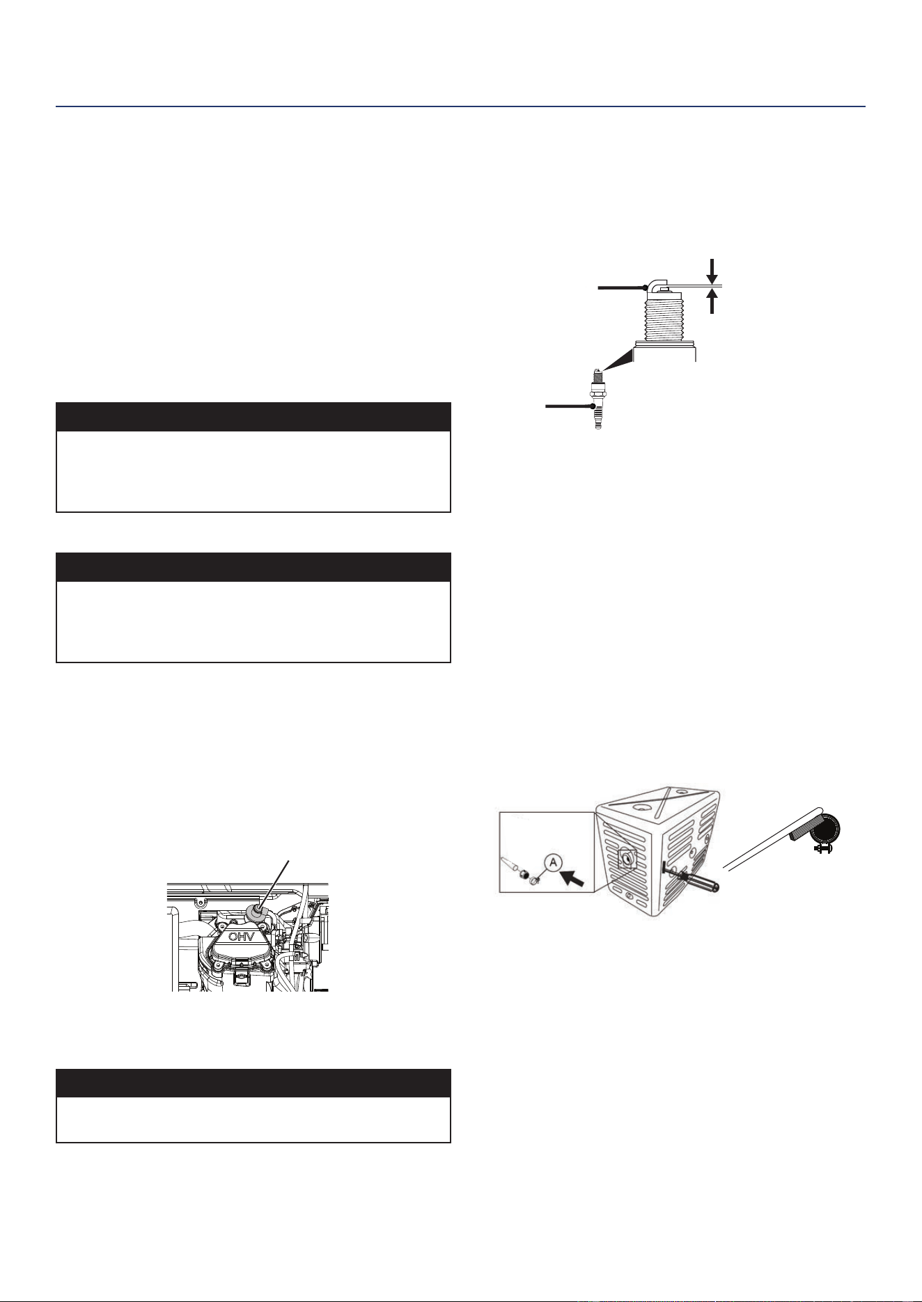
Westinghouse Outdoor Power Equipment, LLC | 49
MANTENIMIENTO
5. Instale el perno de drenaje de aceite y apriételo
rmemente.
Nota: Se recomienda una nueva arandela de presión
del tapón de drenaje de aceite en cada cambio de
aceite.
6. Vierta lentamente aceite en el cuello de llenado de
aceite hasta que el nivel de aceite esté entre las marcas
L y H de la varilla de nivel. Deténgase con frecuencia
para comprobar el nivel de aceite. No llene demasiado.
Capacidad máxima de aceite: 0,74 cuartos (0,7 litros)
7. Instale la varilla medidora de aceite y apriete a mano.
AVISO
No contaminar. Siga las pautas de la EPA u otras
agencias gubernamentales para la eliminación adecuada
de materiales peligrosos. Consulte a las autoridades
locales o al centro de recuperación.
MANTENIMIENTO DE BUJÍAS
AVISO
Utilice siempre una bujía Westinghouse OEM o una
bujía compatible sin resistencia. El uso de bujías de
tipo resistor puede provocar un ralentí brusco, fallas de
encendido o puede impedir que el motor arranque.
Inspeccione y limpie la bujía cada 100 horas de uso o cada
seis meses. Reemplace la bujía después de 300 horas de
uso o cada año.
1. Coloque el generador en una supercie nivelada y deje
que el motor se enfríe.
2. Retire la funda de la bujía tirando rmemente de la
funda de la bujía directamente lejos del motor.
Bota de bujía
3. Limpia el área alrededor de la bujía.
4. Retire la bujía con la llave de tubo de bujía incluida.
AVISO
Nunca aplique ninguna carga lateral ni mueva la bujía
lateralmente al retirar la bujía.
5. Inspeccione la bujía. Reemplácelos si los electrodos
están picados, quemados o si el aislante está
agrietado. Utilice únicamente un enchufe de repuesto
recomendado.
6. Mida el espacio entre los electrodos de la bujía con una
galga de espesores de alambre. Si es necesario, corrija
el espacio doblando con cuidado el electrodo lateral.
Espacio de la bujía: 0.024 – 0.032 in. (0.60 – 0.80 mm)
0.024 - 0.032 in.
(0.60 - 0.80 mm)
Aislante
Electrodo lateral
7. Instale con cuidado la bujía apretándola con los dedos
y luego apriétela con una vuelta adicional de 3/8 a 1/2
con la llave para bujías.
8. Coloque la funda de la bujía.
SERVICIO DE APAGACHISPAS
Deje que el silenciador se enfríe completamente antes de
dar servicio al parachispas. Revise y limpie el parachispas
después de cada 100 horas de uso o cada seis meses. Si
no se limpia el parachispas, se degradará el rendimiento
del motor..
1. Coloque el generador en una supercie nivelada.
2. Deslice el destornillador en la ranura lateral y retire el
tornillo que sujeta la abrazadera (A) en el parachispas.
Extraiga el conjunto del parachispas.
3. Retire con cuidado los depósitos de carbón de la
pantalla del parachispas con un cepillo de alambre.
El parachispas debe estar libre de roturas y roturas.
Reemplace el parachispas si está dañado.
4. Vuelva a instalar el parachispas.
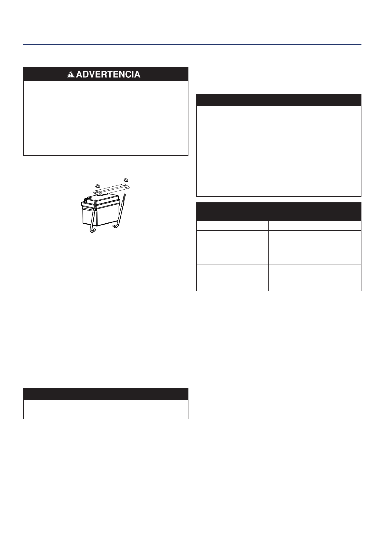
50 | Westinghouse Outdoor Power Equipment, LLC
CAMBIO DE BATERÍA
Mantenga los terminales de la batería cubiertos en todo
momento. El generador se envía con una batería de
iones de litio (Li-Ion). Los terminales metálicos positivos
y negativos expuestos pueden cortocircuitarse cuando
entran en contacto con objetos metálicos, encendiendo
los materiales internos de la celda y expulsando por
la fuerza el contenido en llamas, lo que resulta en
incendios, explosiones, lesiones graves e incluso la
muerte.
1. Aoje y retire los pernos que sujetan la placa de sujeción
de la batería y retire la placa.
2. Desconecte los enchufes de conexión rápida y retire la
batería de la unidad.
3. Desconecte los cables de desconexión rápida de la
batería.
4. En la batería de reemplazo, conecte el cable blanco (-)
de conexión rápida al terminal negativo de la batería.
Deslice la funda de goma sobre el hardware de
conexión.
5. Conecte el cable rojo (+) de conexión rápida al terminal
positivo de la batería. Deslice la funda de goma sobre
el hardware de conexión.
6. Instale la batería en el generador. Vuelva a instalar la
placa de sujeción de la batería y apriete los pernos.
7. Conecte el enchufe de conexión rápida.
AVISO
Deseche la batería usada correctamente de acuerdo con
las pautas establecidas por su gobierno local o estatal.
ALMACENAMIENTO
Se requiere una preparación de almacenamiento adecuada
para un funcionamiento sin problemas y la longevidad del
generador.
AVISO
La gasolina almacenada por tan solo 30 días puede
deteriorarse, causando goma, barniz y acumulación de
corrosivo en las líneas de combustible, los conductos
de combustible y el motor. Esta acumulación corrosiva
restringe el ujo de combustible, lo que puede evitar
que el motor arranque después de un período de
almacenamiento prolongado. El uso de estabilizador de
combustible aumenta signicativamente la vida útil de
la gasolina. Se recomienda el uso de estabilizador de
combustible a tiempo completo. Siga las instrucciones
de uso del fabricante.
TIEMPO DE
ALMACENAMIENTO
RECOMENDADO
PROCEDIMIENTO
Menos de 1 mes No requiere servicio.
2 a 6 meses
Llene con gasolina nueva
y agregue estabilizador de
gasolina. Drene el recipiente
del otador del carburador.
6 meses o más
Drene el tanque de
combustible y el recipiente del
otador del carburador.
ALMACENAMIENTO A CORTO PLAZO
• Deje que el generador se enfríe un mínimo de 30
minutos antes de almacenarlo.
• Reemplace todas las cubiertas protectoras en el panel
de control del generador.
• Limpie el generador con un paño húmedo. Limpie
cualquier residuo de las rejillas de ventilación del
silenciador.
• Almacene el generador en un lugar seco y bien
ventilado, lejos de chispas, llamas abiertas, luces
piloto, calor y otras fuentes de ignición, como áreas con
motores eléctricos que producen chispas o donde se
operan herramientas eléctricas.
• No almacene el generador, los tanques de gasolina
o propano cerca de hornos, calentadores de agua
o cualquier otro aparato que produzca calor o tenga
encendido automático..
• Con el motor y el sistema de escape fríos y todas las
supercies secas, cubra el generador para evitar la
entrada de polvo. No utilice una hoja de plástico como
cubierta antipolvo. Los materiales no porosos atrapan
la humedad y promueven el óxido y la corrosión.
MANTENIMIENTO
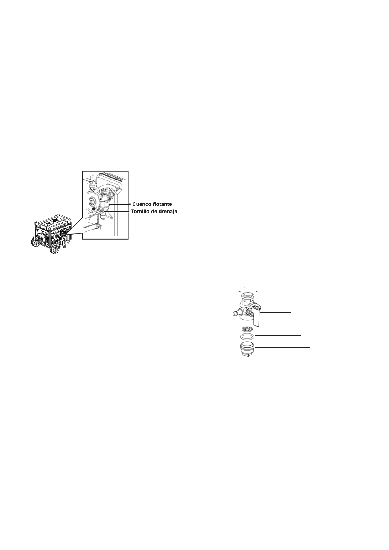
Westinghouse Outdoor Power Equipment, LLC | 51
MANTENIMIENTO
ALMACENAMIENTO A LARGO PLAZO
Incluso el combustible debidamente estabilizado puede
dejar residuos y provocar corrosión si se deja por un
tiempo prolongado. Si almacena el generador durante dos
a seis meses, drene el recipiente del otador para evitar la
acumulación de goma y barniz en el carburador.
DRENAJE DEL BOWL FLOTADOR
1. Gire la válvula del tanque de combustible a la posición
de APAGADO.
2. Localice el tornillo de drenaje en la parte inferior del
recipiente del otador del carburador.
3. Coloque un recipiente de gasolina apropiado debajo del
tornillo de drenaje para recoger el combustible drenado.
4. Aoje el tornillo de drenaje del recipiente del otador y
deje que se drene el combustible. Apriete el tornillo de
drenaje del recipiente del otador.
DRENAJE DEL TANQUE DE COMBUSTIBLE
Si almacena el generador por más de seis meses, drene
el tanque de combustible para evitar la separación del
combustible, el deterioro y los depósitos en el sistema de
combustible.
1. Desenrosque la tapa del tanque de combustible.
Retire el ltro de malla de combustible comprimiéndolo
ligeramente mientras lo saca del tanque.
2. Con una bomba manual de gasolina disponible en el
mercado (no incluida), extraiga la gasolina del tanque
de combustible a un recipiente de gasolina aprobado.
NO use una bomba eléctrica.
3. Vuelva a instalar el ltro de malla de combustible y la
tapa del tanque de combustible.
4. Encienda el generador y déjelo funcionar hasta que el
motor del generador se detenga.
5. Empuje el interruptor Run / Stop a la posición Stop.
6. Retire la bujía.
7. Ponga una cucharadita de aceite de motor en el
cilindro y tire de la manija de retroceso hasta que
sienta resistencia. En esta posición, el pistón sube
en su carrera de compresión y ambas válvulas están
cerradas. Guardar el motor en esta posición ayudará a
prevenir la corrosión interna. Vuelva a colocar el mango
de retroceso con cuidado.
8. Vuelva a instalar la bujía. Deje la funda de la bujía
desconectada para evitar un arranque accidental.
MANTENIMIENTO DE LA VÁLVULA DE
COMBUSTIBLE
La válvula de combustible está equipada con una copa
de sedimentos de combustible, una rejilla y una junta
tórica. La válvula de combustible no requiere servicio si
la unidad se mantiene adecuadamente con combustible
nuevo y limpio. Si se requiere la resolución de problemas
relacionados con el combustible, realice el mantenimiento
de la válvula de combustible.
Retire la junta tórica y la pantalla.
1. Deje que el generador se enfríe por completo.
2. Gire la válvula de combustible a la posición de
APAGADO.
3. Retire la copa de sedimentos de la válvula de
combustible. Retire la junta tórica y la pantalla.
Válvula de gasolina
Pantalla
Junta tórica
Taza
4. Lave la copa de sedimentos, la junta tórica y la pantalla
en un disolvente no inamable. Sécalos bien.
5. Coloque la rejilla y la junta tórica en la válvula de
combustible. Instale la copa de sedimentos y apriétela
rmemente.
6. Gire la válvula de combustible a la posición ON y
verique que no haya fugas. Reemplace la válvula de
combustible si hay alguna fuga.
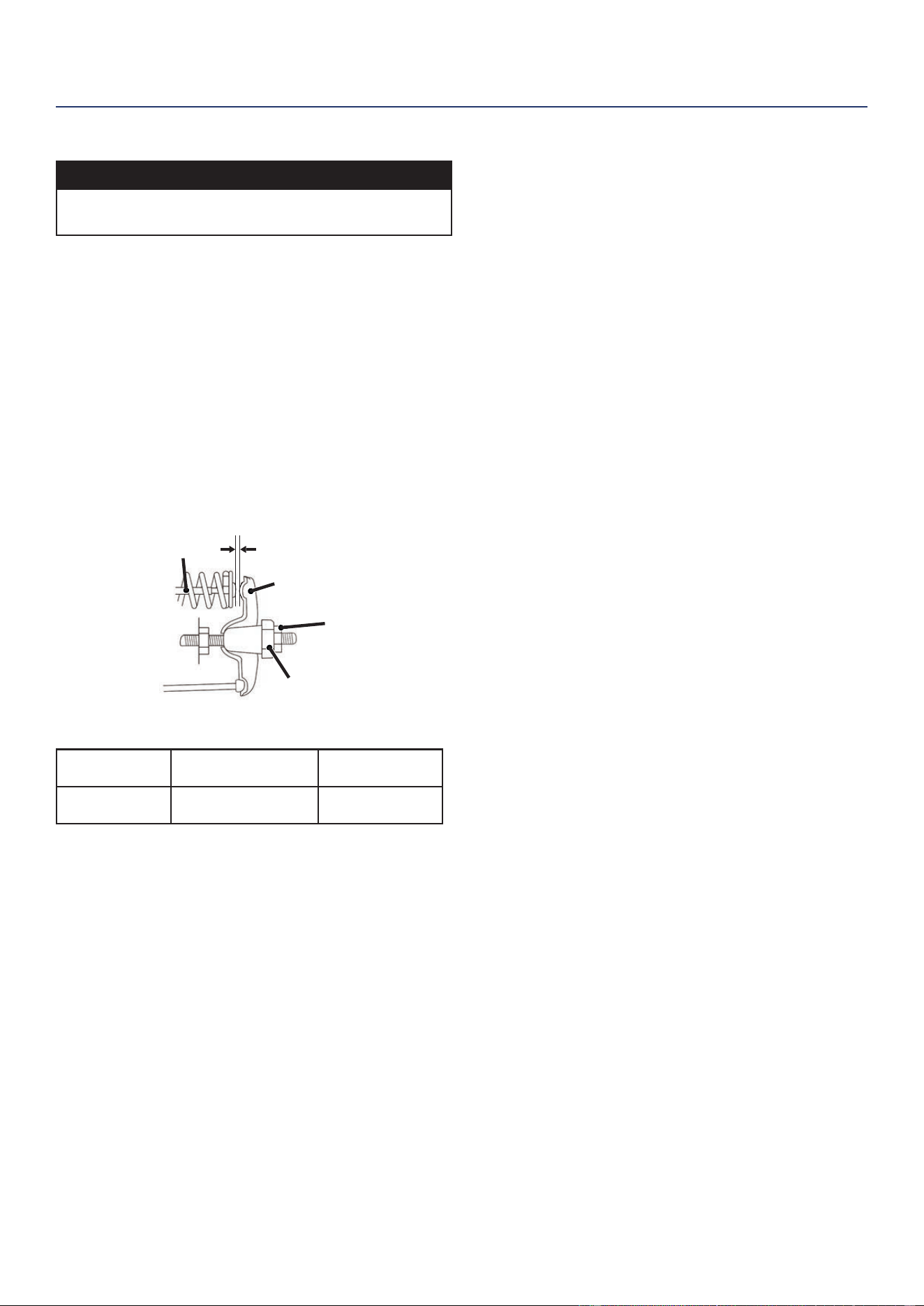
52 | Westinghouse Outdoor Power Equipment, LLC
MANTENIMIENTO
JUEGO DE VÁLVULAS
AVISO
La vericación y el ajuste de la holgura de las válvulas
deben realizarse con el motor frío.
1. Retire la tapa del balancín y retire con cuidado la junta.
Si la junta está rota o dañada, debe reemplazarse.
2. Retire la bujía para que el motor pueda girar más
fácilmente.
3. Gire el motor hasta el punto muerto superior (TDC) tirando
lentamente de la palanca de retroceso. Mirando a través
del oricio de la bujía, el pistón debe estar en la parte
superior (ambas válvulas están cerradas).
4. Ambos balancines deben estar sueltos en el PMS en la
carrera de compresión. Si no es así, gire el motor 360 °.
5. Inserte una galga de espesores entre el balancín y el
vástago de la válvula para medir la holgura de la válvula.
Tuerca de
ajuste de pivote
Vástago de válvula
Balancín
Pivote del balancín
Válvula de admisión Válvula de escape
Juego de
válvulas
0.0031 – 0.0047 in
(0.08 – 0.12 mm)
0.0051 – 0.0067 in
(0.13 – 0.17 mm)
Esfuerzo de
torsión
8-12 N•m 8-12 N•m
6. Si es necesario un ajuste, sostenga el pivote del
balancín y aoje la tuerca de ajuste del pivote.
7. Gire el pivote del balancín para obtener la holgura
especicada. Sostenga el pivote del balancín y vuelva a
apretar la tuerca de ajuste del pivote al par especicado.
Esfuerzo de torsión: 106 pulgada-libra (12 N•m)
8. Realice este procedimiento para la otra válvula.
9. Instale la junta, la tapa del balancín y la bujía.

Westinghouse Outdoor Power Equipment, LLC | 53
SOLUCIÓN DE PROBLEMAS
SOLUCIÓN DE PROBLEMAS
SOLUCIÓN DE PROBLEMAS
PROBLEMA CAUSA POSIBLE CORRECCIÓN
El motor no arranca
Interruptor de batería en la posición de APAGADO. Gire el interruptor de la batería a la posición ON.
Sin combustible. Repostar.
Combustible en mal estado, generador almacenado
sin tratar o drenar gasolina, o repostado con
gasolina en mal estado.
Vacíe el tanque de combustible. Reposte con gasolina nueva.
Filtro de aire sucio. Limpiar el ltro de aire.
El nivel bajo de aceite del motor detuvo el
generador.
Si el LED de aceite bajo se ilumina, gire el interruptor de la
batería a la posición de APAGADO. Agregue aceite de motor.
Bujía mojada con combustible (motor ahogado).
Espere cinco minutos. Gire el interruptor de la batería a
la posición de APAGADO. Tire de la manija de retroceso
rápidamente varias veces. Si el generador no arranca, retire
la bujía y séquelo.
Bujía defectuosa, sucia o mal abierta. Haga un hueco o reemplace la bujía. Reinstalar.
Filtro de combustible restringido, falla del sistema
de combustible, falla de la bomba de combustible,
falla de encendido, válvulas atascadas, etc.
Comuníquese con el servicio al cliente de Westinghouse sin
cargo al 1 (855) 944-3571.
Batería drenada.
Utilice la palanca de retroceso para encender el generador.
Carga la batería
Ahogador parcialmente abierto o cerrado debido a
batería débil o desconectada.
Congure manualmente el estrangulador. Vea la sección de
Mantenimiento.
El motor arranca y luego se
apaga
Sin combustible. Repostar
Nivel de aceite de motor incorrecto. Revise el nivel de aceite del motor.
Filtro de aire sucio. Limpiar el ltro de aire.
Combustible contaminado. Vacíe el tanque de combustible. Reposte con gasolina nueva.
Interruptor de nivel de aceite bajo defectuoso.
Comuníquese con el servicio al cliente de Westinghouse sin
cargo al 1 (855) 944-3571.
El motor carece de potencia
Filtro de aire restringido. Limpiar o reemplazar el ltro de aire.
Combustible en mal estado, generador almacenado
sin tratar o drenar gasolina, o repostado con
gasolina en mal estado.
Vacíe el tanque de combustible. Reposte con gasolina nueva.
Filtro de combustible restringido, falla del sistema
de combustible, falla de la bomba de combustible,
falla de encendido, válvulas atascadas, etc.
Comuníquese con el servicio al cliente de Westinghouse sin
cargo al 1 (855) 944-3571.
El motor funciona con
dicultad o se atasca cuando
se aplica carga
Filtro de aire sucio. Limpiar el ltro de aire.
Generador sobrecargado. Desenchufe algunos dispositivos.
Herramienta o aparato eléctrico defectuoso.
Reemplace o repare la herramienta o el electrodoméstico.
Detenga y vuelva a arrancar el motor.
Filtro de combustible restringido, falla del sistema
de combustible, falla de la bomba de combustible,
falla de encendido, válvulas atascadas, etc.
Comuníquese con el servicio al cliente de Westinghouse sin
cargo al 1 (855) 944-3571.
No hay energía en los
receptáculos de CA
El LED de SALIDA LISTA está APAGADO y el LED
DE SOBRECARGA está ENCENDIDO.
Verique la carga de CA. Detenga y vuelva a arrancar el
motor.
Verique la entrada de aire. Detenga y vuelva a arrancar el
motor.
Se dispararon los disyuntores de CA. Verique las cargas de CA y reinicie los disyuntores.
Herramienta o aparato eléctrico defectuoso.
Reemplace o repare la herramienta o el electrodoméstico.
Detenga y vuelva a arrancar el motor.
Generador defectuoso.
Comuníquese con el servicio al cliente de Westinghouse sin
cargo al 1 (855) 944-3571.

54 | Westinghouse Outdoor Power Equipment, LLC
NE PAS RETOURNER CE PRODUIT AU MAGASIN
Si vous avez des questions ou avez besoin d’aide,
veuillez appeler le service client au 855-944-3571.
MANUEL DE L’UTILISATEUR
FRANÇAIS
WGen5300
Générateur Portable
ESSENCE: Puissance d’opération 5300 Watts | Puissance de pointe 6600 Watts
TABLE DES MATIÈRES
INTRODUCTION
AVIS DE NON-RESPONSABILITÉ ........................................55
ENREGISTREMENT DU PRODUIT
......................................55
CARACTÉRISTIQUES
...........................................................56
MISES À JOUR
...................................................................... 56
SÉCURITÉ
DÉFINITIONS DE SÉCURITÉ ...............................................57
SYMBOLES DE SÉCURITÉ
.................................................57
CONSIGNES DE SÉCURITÉ
................................................58
PRÉCAUTIONS GÉNÉRALES DE SÉCURITÉ
.....................58
ESSENCE ET VAPEUR D’ESSENCE (GAZ)
.........................59
AUTOCOLLANTS DE SÉCURITÉ
.........................................60
COMPOSANTS
COMPOSANTS DU PANNEAU DE COMMANDE ................. 61
COMPOSANTS DU GÉNÉRATEUR
......................................62
ASSEMBLÉ
CONTENU DU CARTON .......................................................63
INSTALLER LES PIEDS ET LES ROUE
................................63
REMPLISSAGE D’HUILE INITIAL
.........................................63
CARBURANT
.........................................................................64
REMPLIR LE RÉSERVOIR DE CARBURANT
......................65
CONNECTEZ LA BATTERIE
.................................................65
EMPLACEMENT DU GÉNÉRATEUR
....................................65
OPÉRATION
MISE À LA TERREMISE À LA TERRE ..................................66
FONCTIONNEMENT À HAUTE ALTITUDE
........................... 66
COMMUTATEUR DE SÉLECTION DE TENSION
.................66
DÉMARRAGE À DISTANCE
..................................................66
AVANT DE DÉMARRER LE GÉNÉRATEUR
.........................67
DÉMARRAGE DU MOTEUR: ESSENCE
..............................67
ARRÊT DU MOTEUR
............................................................68
FRÉQUENCE D’UTILISATION
..............................................68
DISJONCTEURS AC
.............................................................68
CAPACITÉ DU GÉNÉRATEUR
..............................................68
RALLONGES
.........................................................................69
DIMENSIONS DU CORDON D’EXTENSION
........................70
ENTRETIEN
CALENDRIER DE MAINTENANCE ....................................... 71
RAPPELS D’ENTRETIEN
...................................................... 71
PIÈCES DE RECHANGE D’ENTRETIEN
.............................. 71
ENTRETIEN DU FILTRE À AIR
.............................................71
CONTRÔLE DU NIVEAU D’HUILE MOTEUR
.......................72
CHANGEMENT D’HUILE MOTEUR
......................................72
ENTRETIEN DE LA BATTERIE
.............................................73
REMPLACEMENT DE LA BATTERIE
.................................... 73
MAINTENANCE DES BOUGIES
...........................................73
SERVICE DE PARE-ÉTINCELLES
........................................ 74
ESPACE DE RANGEMENT
...................................................74
LE JEU DES SOUPAPES
......................................................76
REMARQUER
........................................................................ 76
DÉPANNAGE
DÉPANNAGE ......................................................................... 77

Westinghouse Outdoor Power Equipment, LLC | 55
WGen5300
Générateur Portable
ESSENCE: Puissance d’opération 5300 Watts | Puissance de pointe 6600 Watts
INTRODUCTION
INTRODUCTION
MISE EN GARDE: L’utilisation, l’entretien et la maintenance de cet équipement peuvent vous exposer à des
produits chimiques, notamment les gaz d’échappement du moteur, le monoxyde de carbone, les phtalates et le
plomb, qui sont connus dans l’État de Californie pour provoquer le cancer et des anomalies congénitales ou d’autres
troubles de la reproduction. Pour minimiser l’exposition, évitez de respirer les gaz d’échappement et portez des gants
ou lavez-vous les mains fréquemment lors de l’entretien de cet équipement. Pour plus d’informations, visitez le site
www.P65warnings.ca.gov.
AVIS DE NON-RESPONSABILITÉ
Toutes les informations, illustrations et spécications de ce manuel étaient en vigueur au moment de sa publication. Les
illustrations utilisées dans ce manuel sont uniquement destinées à être des vues de référence représentatives. Nous
nous réservons le droit d’apporter toute spécication ou modication de conception sans préavis.
Tous les droits sont réservés. Aucune reproduction autorisée sous quelque forme que ce soit sans l’autorisation écrite
de Westinghouse Outdoor Power Equipment, LLC.
Lisez ce manuel avant d’utiliser ou d’effectuer
des opérations de maintenance sur ce
produit. Le non-respect des instructions et des
précautions de sécurité de ce manuel peut
entraîner des blessures graves ou la mort.
CONSERVEZ CES INSTRUCTIONS
ENREGISTREMENT DU PRODUIT
Pour une couverture de garantie sans problème, il est important d’enregistrer votre génératrice Westinghouse.
Vous pouvez vous inscrire par:
• Remplir et envoyer par la poste la carte d’enregistrement du produit incluse dans le carton.
• Enregistrement de votre produit en ligne sur: https://westinghouseoutdoorpower.com/pages/warranty-registration
• Scanner le code QR suivant avec l’appareil photo de votre smartphone. Vous serez dirigé vers le lien d’inscription
mobile.
• Envoi des informations produit suivantes à:
Westinghouse Outdoor Power
Warranty registration
777 Manor Park Drive
Columbus, OH 43228
Pour vos dossiers
Date d’achat:
Numéro de modèle:
Numéro de série:
Lieu d’achat:
IMPORTANT: Conservez votre reçu d’achat pour une couverture de garantie sans problème.
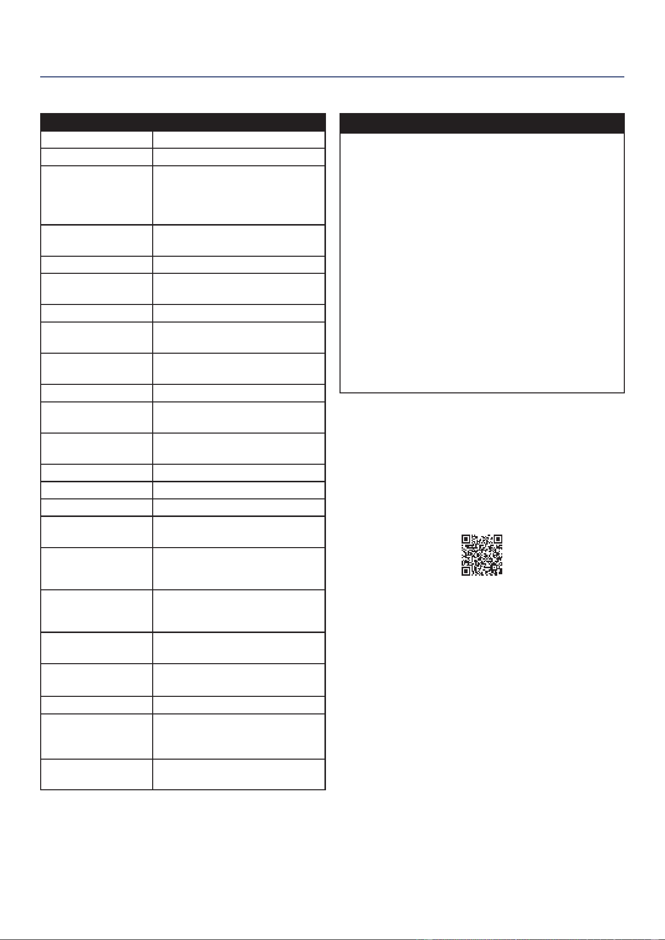
56 | Westinghouse Outdoor Power Equipment, LLC
CARACTÉRISTIQUES
Caractéristiques
Watts courants: 5300
Watts de pointe: 6600
Puissance
nominale à
1,0 facteur de
puissance:
5.3 kW
Puissance de
crête:
6.6 kVA
Tension nominale: 120V/240V
Fréquence
nominale:
60 Hz @ 3600 RPM
Phase: Monophasé
Distorsion
harmonique totale:
≤ 23%
Déplacement du
moteur:
274 cc
Type de départ: Recul, démarrage électrique
Capacité de
carburant:
4,7 gallons (18 litres)
Type de carburant: Essence sans plomb
87–93 octane*
Capacité d'huile: 0,74 quart (0,7 litre)
Type d'huile: SAE 10W-30
Bougie d'allumage: 97108 (F7TC)
Ecartement
électrode bougie:
0.024 – 0.032 in.
(0.60 – 0.80 mm)
Admission de
valve
Dégagement:
0.0031 – 0.0047 in.
(0.08 – 0.12 mm)
Échappement de
soupape
Dégagement:
0.0051 – 0.0067 in.
(0.13 – 0.17 mm)
Système de mise à
la terre AC:
Flotante neutral
Régulateur de
tension:
AVR
Type d'alternateur: Brossé
Température
ambiante
maximale:
104°F (40°C)
Certications:
• EPA
• CARB
* Teneur en éthanol de 10% ou moins. N’utilisez PAS E15
ou E85.
MISES À JOUR
Le dernier manuel d’utilisation de votre générateur
Westinghouse se trouve sous notre onglet d’assistance.
https://westinghouseoutdoorpower.com/pages/
manuals
Ou scannez le code QR suivant avec l’appareil photo de
votre smartphone pour être dirigé vers le lien.
CARACTÉRISTIQUES
AVIS
Ce produit est conçu et conçu pour un fonctionnement
continu à des températures ambiantes allant jusqu’à 40
° C (104 ° F). Si nécessaire, ce produit peut être utilisé
à des températures allant de 5 ° F (15 ° C) à 122 ° F
(50 ° C) pendant de courtes périodes. Si le produit est
exposé à des températures en dehors de cette plage
pendant le stockage, il doit être ramené dans cette plage
avant utilisation. Ce produit doit toujours être utilisé à
l’extérieur dans un endroit bien ventilé et loin des portes,
fenêtres et autres évents.
La puissance et le courant maximum sont soumis
et limités par des facteurs tels que la teneur en BTU
de carburant, la température ambiante, l’altitude, les
conditions du moteur, etc. La puissance maximale
diminue d’environ 3,5% pour chaque 1000 pieds au-
dessus du niveau de la mer, et diminuera également
d’environ 1% pour chaque 10 ° F (6 ° C) au-dessus de la
température ambiante de 60 ° F (16 ° C).
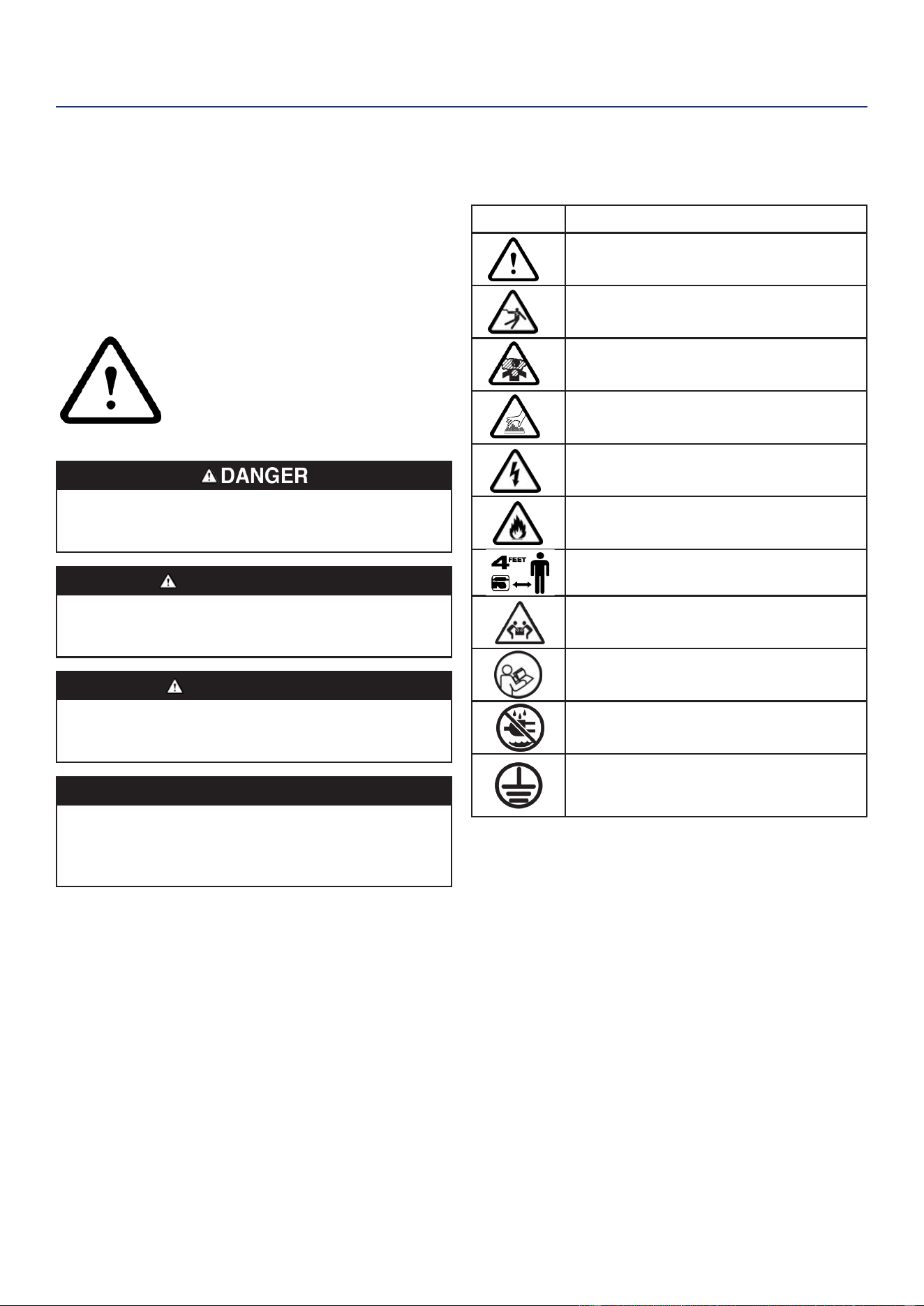
Westinghouse Outdoor Power Equipment, LLC | 57
SÉCURITÉ
SÉCURITÉ
DÉFINITIONS DE SÉCURITÉ
Les mots DANGER, AVERTISSEMENT, ATTENTION et
AVIS sont utilisés tout au long de ce manuel pour mettre
en évidence des informations importantes. Assurez-vous
que la signication de ces informations de sécurité est
connue de tous ceux qui utilisent, effectuent des travaux
de maintenance ou se trouvent à proximité du générateur.
Ce symbole d’alerte de sécurité
apparaît avec la plupart des
déclarations de sécurité. Il signie
attention, devenez alerte, votre
la sécurité est en jeu! Veuillez lire et
respecter le message qui suit
le symbo d’alertes de sécuritél.
Indique une situation dangereuse qui, si elle n’est
pas évitée, entraînera la mort ou des blessures
graves.
AVERTISSEMENT
Indique une situation dangereuse qui, si elle
n’est pas évitée, pourrait entraîner la mort ou des
blessures graves.
MISE EN GARDE
Indique une situation dangereuse qui, si elle
n’est pas évitée, pourrait entraîner des blessures
mineures ou modérées.
AVIS
Indique une situation qui peut endommager
le générateur, les biens personnels et/ou
l’environnement, ou entraîner un mauvais
fonctionnement de l’équipement.
Remarque: Indique une procédure, une pratique ou une
condition à suivre pour que le générateur
fonctionne de la manière prévue.
SYMBOLES DE SÉCURITÉ
Suivez toutes les informations de sécurité contenues
dans ce manuel et sur le générateur.
Symbole La description
Symbole d’alerte de sécurité
Risque d’électrocution
Risque d’asphyxie
Risque de brûlure. Ne touchez pas les
surfaces chaudes.
Risque d’électrocution
Risque d’incendie
Maintenez une distance de sécurité
Risque de levage
Lire les instructions du fabricant
Ne pas utiliser dans des conditions
humides
Terre. Consultez un électricien pour
déterminer les exigences de mise à la
terre avant l’utilisation.
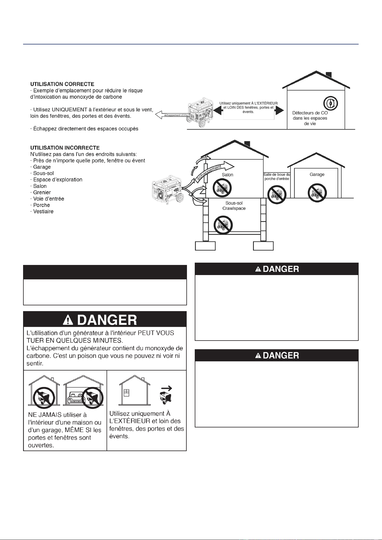
58 | Westinghouse Outdoor Power Equipment, LLC
CONSIGNES DE SÉCURITÉ
AVIS
Installez des détecteurs de monoxyde de carbone à piles
ou des détecteurs de monoxyde de carbone enchables
avec pile de secours dans les pièces à vivre.
Risque d’incendie et d’électrocution. Ne pas connecter
au système électrique d’un bâtiment à moins que le
générateur et le commutateur de transfert n’aient été
correctement installés et que la sortie électrique ait été
vériée par un électricien qualié. La connexion doit
isoler l’alimentation du générateur de l’alimentation
secteur et doit être conforme à toutes les lois et codes
électriques applicables.
Risque d’électrocution. N’utilisez jamais le générateur
dans un endroit mouillé ou humide. N’exposez jamais le
générateur à la pluie, à la neige, aux projections d’eau
ou à l’eau stagnante pendant son utilisation. Protégez
le générateur de toutes les conditions météorologiques
dangereuses. L’humidité ou la glace peuvent provoquer
un court-circuit ou un autre dysfonctionnement dans le
circuit électrique.
PRÉCAUTIONS GÉNÉRALES DE SÉCURITÉ
• N’utilisez jamais le générateur pour alimenter du
matériel médical.
• N’utilisez pas le générateur lorsque vous êtes fatigué
ou sous l’inuence de drogues, d’alcool ou de
médicaments.
SÉCURITÉ

Westinghouse Outdoor Power Equipment, LLC | 59
SÉCURITÉ
• N’utilisez pas le générateur avec des cordons
électriques usés, eflochés, dénudés ou autrement
endommagés.
• Tous les outils et appareils électriques alimentés par ce
générateur doivent être correctement mis à la terre à
l’aide d’un troisième l ou être à double isolation.
• Lorsque ce générateur est utilisé pour alimenter un
système de câblage de bâtiment, le générateur doit
être installé par un électricien qualié et connecté
à un commutateur de transfert en tant que système
dérivé séparément conformément à NFPA 70, National
Electrical Code.
• Si vous commencez à vous sentir malade,
étourdi ou faible en utilisant le générateur, passez
IMMÉDIATEMENT à l’air frais. Consultez un médecin,
car vous pouvez avoir une intoxication au monoxyde
de carbone.
• Utilisez uniquement À L’EXTÉRIEUR et loin des
fenêtres, des portes et des évents, comme recommandé
par le Département américain de la Santé et les Centres
des services sociaux pour le contrôle et la prévention
des maladies. Votre domicile et/ou vos conditions de
vent spéciques peuvent nécessiter une distance
supplémentaire.
• Pendant le fonctionnement et le stockage, gardez au
moins 5 pieds de dégagement de tous les côtés de la
génératrice, y compris les frais généraux. Laisser le
générateur refroidir au moins 30 minutes avant de le
ranger. La chaleur créée par le silencieux et les gaz
d’échappement peut être sufsamment chaude pour
provoquer de graves brûlures et/ou enammer des
objets combustibles.
• Ne touchez ni le silencieux ni le moteur. Ils sont très
CHAUDS et provoqueront de graves brûlures. Ne placez
pas de parties du corps ou de matériaux inammables
ou combustibles sur le chemin direct de l’échappement.
• Retirez toujours tous les outils ou autres équipements
de service utilisés pendant la maintenance loin du
générateur avant de l’utiliser.
• Évitez tout contact cutané avec l’huile moteur ou
l’essence. Portez des vêtements et des équipements
de protection. Laver toute la peau exposée avec du
savon et de l’eau.
• Un commutateur de transfert doit être installé par un
électricien agréé et approuvé par l’autorité compétente.
L’installation doit être conforme à toutes les lois et
codes électriques applicables.
SÉCURITÉ DU CARBURANT
• Stockez le carburant dans un contenant approuvé pour
l’essence.
• Ne pas fumer lors du remplissage du générateur avec
de l’essence.
• Ne laissez pas le réservoir d’essence du générateur
déborder lors du remplissage.
• Arrêtez le moteur et laissez-le refroidir pendant cinq
minutes avant d’ajouter de l’essence ou de l’huile au
générateur.
• Ne retirez jamais le bouchon du réservoir lorsque
le générateur est en marche. Arrêtez le moteur et
laissez l’appareil refroidir pendant au moins cinq
minutes. Retirez lentement le bouchon du réservoir
pour relâcher la pression, empêcher le carburant de
s’échapper autour du bouchon et éviter que la chaleur
du silencieux ne déclenche les vapeurs de carburant.
Serrez fermement le bouchon du réservoir après avoir
fait le plein.
• Essuyez le carburant renversé de l’unité.
• N’essayez jamais de brûler du carburant renversé.
• Ne remplissez jamais trop le réservoir de carburant.
Laissez de la place pour que le carburant se dilate.
Un remplissage excessif du réservoir de carburant
peut entraîner un débordement soudain d’essence et
entraîner le déversement d’essence en contact avec
des surfaces CHAUDES.
• Le carburant renversé peut s’enammer. Si du carburant
est renversé sur le générateur, essuyez immédiatement
tout déversement. Jetez le chiffon correctement.
Laisser sécher la zone de carburant renversé avant de
faire fonctionner le générateur.
• Portez des lunettes de protection lors du ravitaillement.
• N’utilisez jamais d’essence comme agent de nettoyage.
• Entreposez tout contenant contenant de l’essence
dans un endroit bien ventilé, loin de tout combustible
ou source d’inammation.
ESSENCE ET VAPEUR D’ESSENCE (GAZ)
Risque d’incendie et d’explosion. L’essence est
hautement explosive et inammable et peut causer de
graves brûlures ou la mort.
• En cas d’incendie au gaz, n’essayez pas d’éteindre la
amme si le robinet de carburant est en position gaz.
L’introduction d’un extincteur dans une génératrice
avec un robinet de carburant ouvert pourrait créer un
risque d’explosion.
• Le gaz a une odeur distinctive, cela aidera à détecter
rapidement les fuites potentielles.
• Les vapeurs de gaz peuvent provoquer un incendie si
elles sont enammées.
• L’essence est un irritant pour la peau et doit être
nettoyée immédiatement si elle entre en contact avec
la peau.

60 | Westinghouse Outdoor Power Equipment, LLC
SÉCURITÉ
AUTOCOLLANTS DE SÉCURITÉ
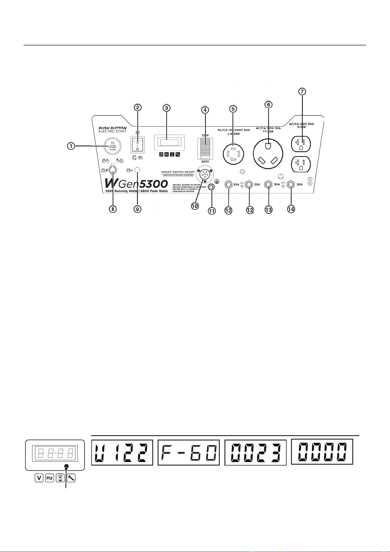
Westinghouse Outdoor Power Equipment, LLC | 61
COMPOSANTS
COMPOSANTS DU PANNEAU DE
COMMANDE
COMPOSANTS
1. Bouton-poussoir START/STOP: Appuyez une fois
pour démarrer automatiquement le moteur. Appuyez
à nouveau pour arrêter le moteur.
2. Commutateur de batterie: allume et éteint la batterie.
Doit être allumé avant le démarrage électrique ou à
distance.
3. Centre de données: basculez pour afcher la
tension, la fréquence, le compteur horaire total et
la minuterie d'exécution/de maintenance.
4. Commutateur de sélection de tension:
sélectionnez 120 volts ou 240 volts. Arrêtez le
générateur avant de commuter les tensions.
5. Prise 120/240 volts CA, 30 A NEMA L14-30R
Twist-Lock: la prise peut fournir un maximum de
30 ampères
6. Prise NEMA TT-30R 120 volts CA, 30 A: la prise
peut fournir un maximum de 30 ampères.
7. Prises NEMA 5-20R duplex de 120 volts CA, 20
A: Les prises peuvent fournir un maximum de 20
ampères.
8. Port de chargement de la batterie: utilisé pour
charger la batterie avec le chargeur de batterie inclus.
9. Indicateur de batterie: indique que l’alimentation
est allumée. La lumière restera allumée pendant que
l’unité est allumée.
10. Prise pour interrupteur intelligent: connecte
l’interrupteur Westinghouse ST (vendu séparément)
au panneau de commande.
11. Borne de terre: La borne de terre est utilisée pour
mettre à la terre extérieurement le générateur.
12. Disjoncteurs de 22 A: Chaque disjoncteur limite
le courant qui peut être délivré à travers chaque
jambe de 120 Volts sur L14-30R à 22 Ampères.
13. Disjoncteur CA 20 A: Le disjoncteur limite le
courant qui peut être fourni par les prises NEMA
5-20R à 20 A.
14. Disjoncteur CA 30 A: Le disjoncteur limite le
courant qui peut être fourni par la prise TT-30R à
30 A.
Achage des données
La fréquence (Hz):
Ache la fréquence de
sortie de puissance en
Hertz
Tension:
Ache la sortie de
tension actuelle
Bouton de mode
METER V-F-T
Durée d'exécution /
maintenance:
Ache la durée d'exécution
actuelle. Remise à zéro à la
fermeture vers le bas.
Maintenance rappel aché
si nécessaire.
Heures de vie:
ache les heures de
fonctionnement à vie
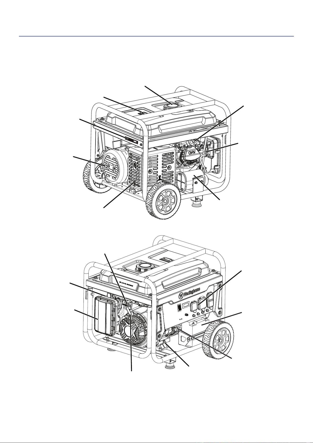
62 | Westinghouse Outdoor Power Equipment, LLC
COMPOSANTS DU GÉNÉRATEUR
Tapa de combustible
Indicador de combustible
Silencieux / pare-étincelles
Navire en carbone
Carburateur
Couvercle d'alternateur
Bougie d'allumage
Numéro de série
Verrouiller
vidange d'huile
Jauge
huile / bouche de
remplir
Panneau
de commande
Entrée
dos
Filtre à air
Soupape
Réservoir de carburant
Levier
Manette de Gaz
Tambours
COMPOSANTS
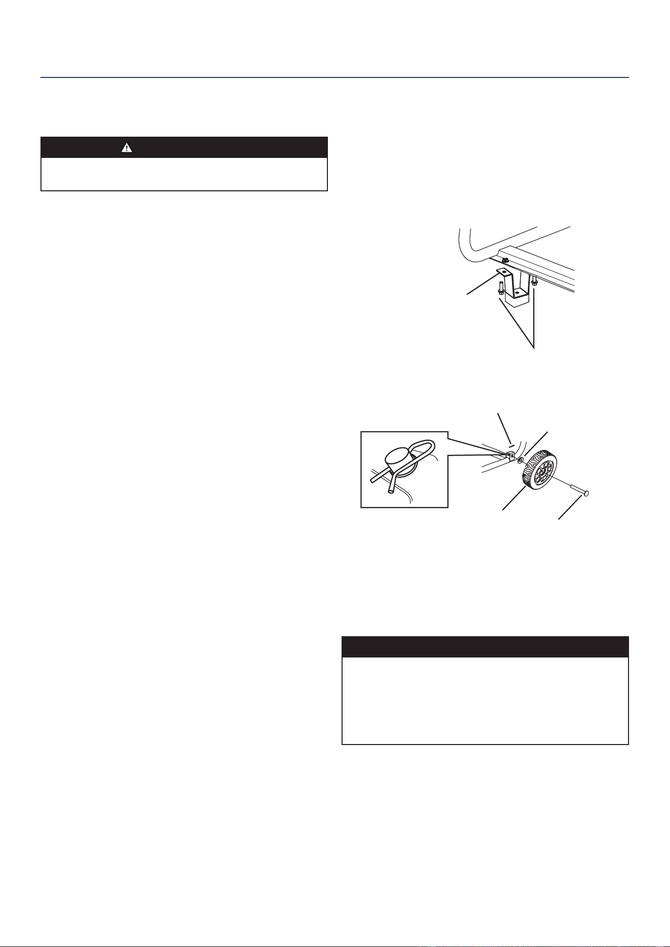
Westinghouse Outdoor Power Equipment, LLC | 63
ASSEMBLÉ
ASSEMBLÉ
CONTENU DU CARTON
MISE EN GARDE
Risque de poids. Ayez toujours de l’aide pour soulever
le générateur.
1. Ouvrez soigneusement le carton.
2. Retirez et conservez le contenu du carton.
3. Retirez et jetez le plateau d’emballage.
4. Dépliez le haut du sac en plastique renfermant le
générateur.
5. Coupez soigneusement les coins verticaux du carton
pour accéder au générateur.
6. Recyclez ou éliminez correctement les matériaux
d’emballage.
CONTENU DU CARTON
• Manuel de l’Utilisateur
• Guide de démarrage rapide
• Bouteille d’huile SAE 10W-30
• Clé à douille de bougie
• Clé
• Chargeur de batterie
Article Montant
• Pied de montage 2
• Boulon à bride, M8 4
• Roue 2
• Axe d’arbre 2
• Machine à laver 2
• Goupille 2
S’il manque des pièces, contactez notre équipe de
service à [email protected] ou appelez le 1-855-
944-3571.
INSTALLER LES PIEDS ET LES ROUE
1. Placer le générateur sur une surface plane.
2. Basculez le générateur sur un morceau de carton ou
un autre matériau souple pour protéger la peinture du
cadre et empêcher le générateur de glisser.
3. Avec la clé fournie, installez les pieds de montage sur
le cadre comme indiqué.
Pied de montage
Boulons de bride
4. Installez les roues comme indiqué.
Axe d'essieu
Roue
Goupille
Machine à laver
Remarque: Les roues sont uniquement destinées au
transport manuel. Les roues ne sont pas
adaptées au remorquage du générateur sur
route ou hors route.
REMPLISSAGE D’HUILE INITIAL
AVIS
CE GÉNÉRATEUR A ÉTÉ EXPÉDIÉ SANS HUILE.
N’essayez pas de lancer ou de démarrer le moteur
avant qu’il n’ait été correctement entretenu avec l’huile
recommandée. Le fait de ne pas ajouter d’huile moteur
avant le démarrage entraînera de graves dommages au
moteur.
Le type d’huile recommandé pour une utilisation typique
est l’huile moteur 10W-30. Si vous utilisez le générateur
à des températures extrêmes, reportez-vous au tableau
suivant.
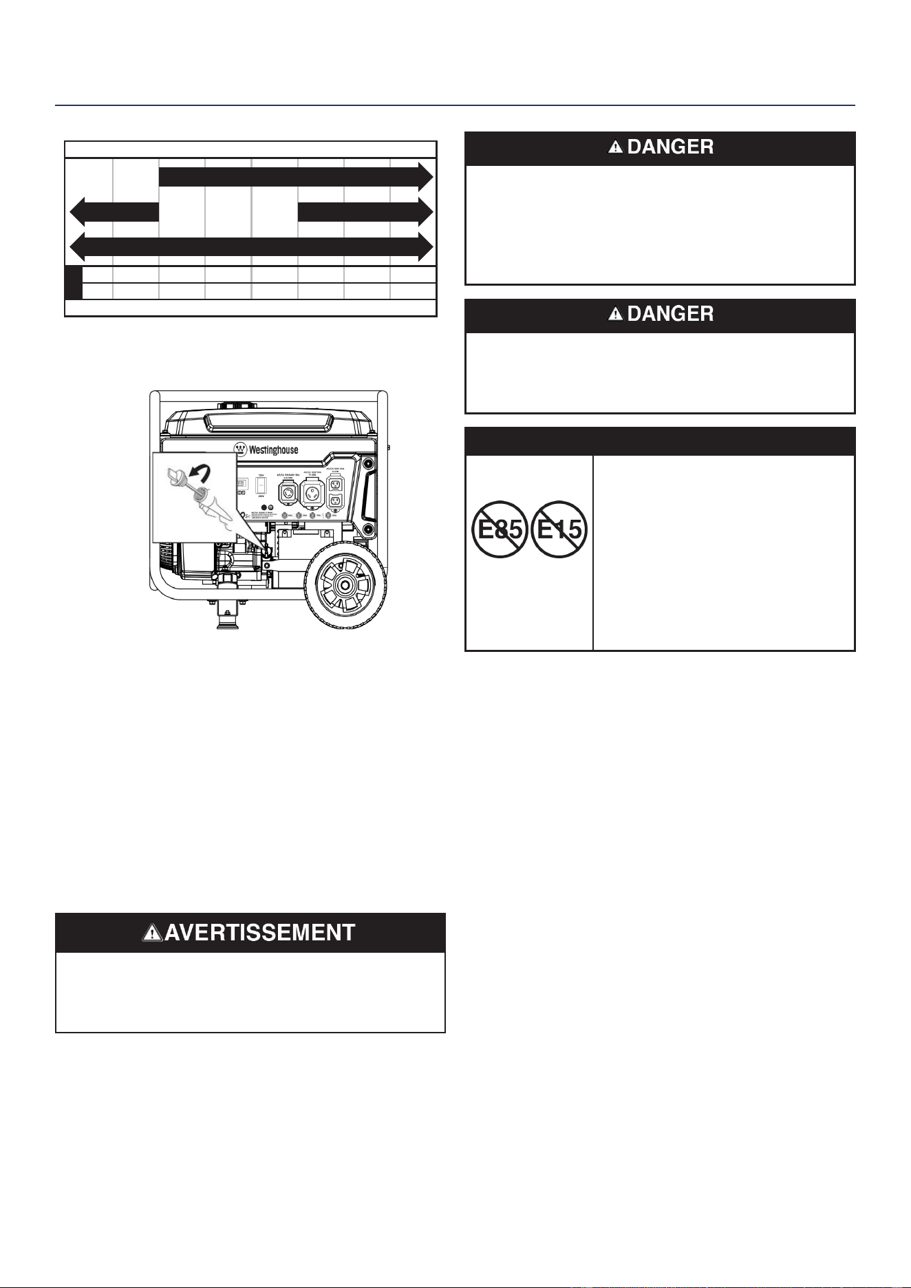
64 | Westinghouse Outdoor Power Equipment, LLC
ASSEMBLÉ
-20 0 20 40 60
Température ambiante
Type d'huile moteur recommandé
80 100 120
-28.9
°F
°C -17.8 -6.7 4.4 15.6 26.7 37.8 48.9
10W-30
5W-30 Synthétique
10W-405W-30
1. Sur une surface plane, retirez la jauge d’huile.
2. À l’aide de l’entonnoir et de l’huile fournis, ajoutez de
l’huile dans le goulot de remplissage d’huile.
Remarque: Comme de l’huile résiduelle de l’usine
peut rester dans le moteur, ajoutez l’huile
progressivement vers l’extrémité de la
bouteille pour éviter de trop remplir le moteur.
Voir Contrôle du niveau d’huile moteur dans la
section Entretien.
3. Essuyez la jauge d’huile. Remplacez la jauge d’huile et
serrez à la main.
CARBURANT
Risque d’incendie et d’explosion. N’utilisez jamais
de bidon d’essence, de réservoir d’essence ou tout
autre élément de carburant cassé, coupé, déchiré ou
endommagé.
Risque d’incendie et d’explosion. Ne remplissez pas
trop le réservoir de carburant. Remplissez uniquement
jusqu’à l’anneau de remplissage rouge situé dans le ltre
à carburant dans le réservoir. Un remplissage excessif
peut entraîner un déversement de carburant sur le
moteur et provoquer un incendie ou une explosion.
Risque d’incendie et d’explosion. Ne faites jamais le
plein de la génératrice lorsque le moteur tourne. Arrêtez
toujours le moteur et laissez le générateur refroidir
pendant deux minutes avant de faire le plein.
AVIS
N’utilisez pas de carburant E15 ou
E85 dans ce produit. Les dommages
au moteur ou à l’équipement
causés par du carburant périmé ou
par l’utilisation de carburants non
approuvés (tels que les mélanges
d’éthanol E15 ou E85) ne sont pas
couverts par la garantie. N’utilisez
que de l’essence sans plomb
contenant jusqu’à 10% d’éthanol.
BESOINS EN CARBURANT
• Essence sans plomb PROPRE, FRAÎCHE, 87–93
octane.
• Jusqu’à 10% d’éthanol (essence-alcool) est acceptable
(le cas échéant; un carburant sans éthanol est
recommandé).
• N’utilisez PAS E85 ou E15.
• NE PAS utiliser de mélange de gazole.
• NE PAS modier le moteur pour qu’il fonctionne avec
des carburants alternatifs.
• NE PAS faire le plein à l’intérieur.
• NE PAS créer d’étincelle ou de amme pendant le
ravitaillement.
UTILISATION DU STABILISATEUR DE
CARBURANT
L’ajout d’un stabilisateur de carburant (non inclus) prolonge
la durée de vie utile du carburant et aide à empêcher la
formation de dépôts qui peuvent obstruer le système de
carburant. Suivez les instructions d’utilisation du fabricant.
Mélangez toujours la bonne quantité de stabilisateur de
carburant à l’essence dans un bidon d’essence approuvé
avant de faire le plein de la génératrice. Faites fonctionner
le générateur pendant cinq minutes pour permettre au
stabilisateur de traiter tout le système d’alimentation en
carburant.
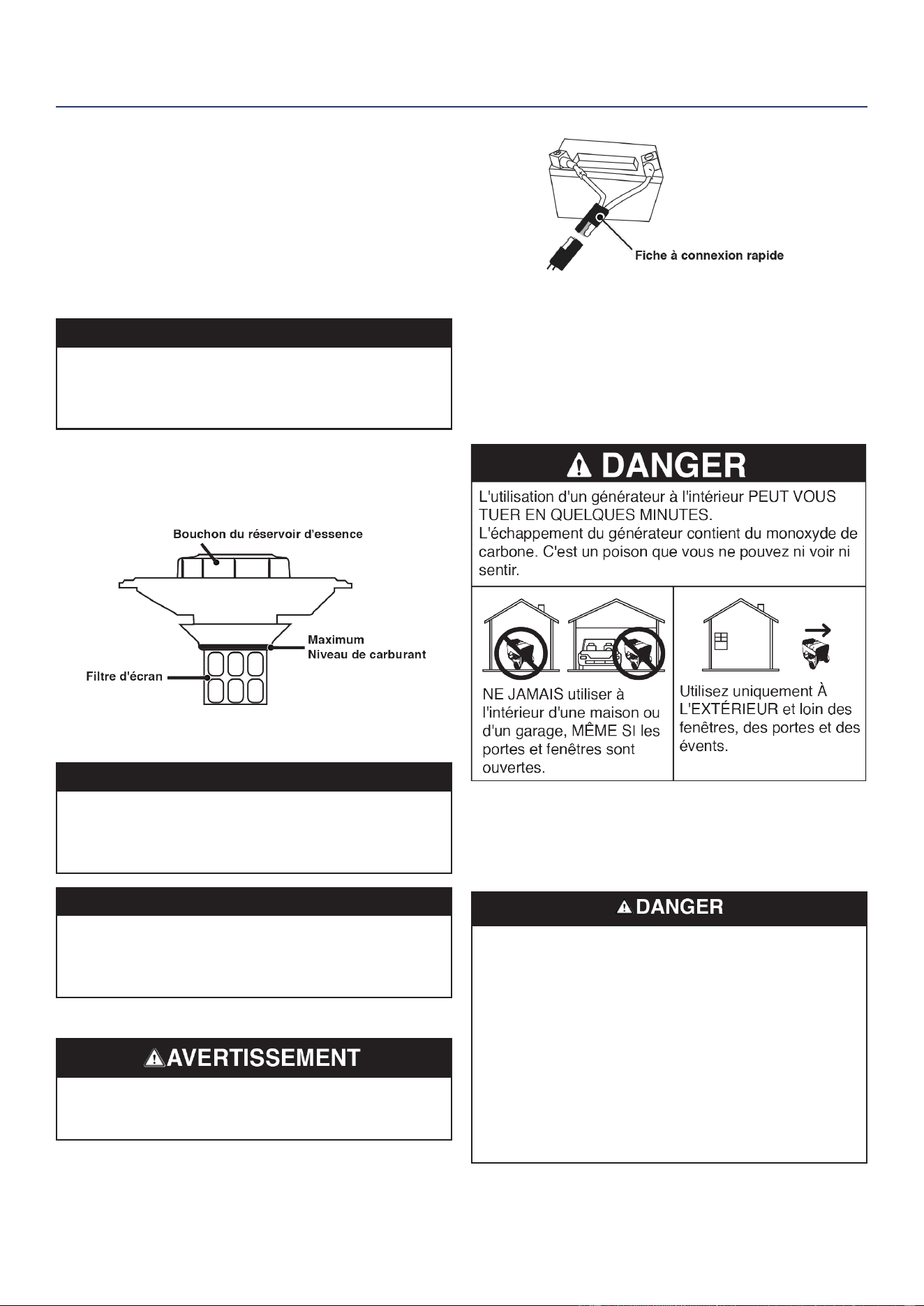
Westinghouse Outdoor Power Equipment, LLC | 65
REMPLIR LE RÉSERVOIR DE CARBURANT
1. Éteignez le générateur et laissez-le refroidir pendant au
moins deux minutes avant de faire le plein.
2. Placez le générateur sur un sol plat dans un endroit
bien ventilé.
3. Nettoyez la zone autour du bouchon de carburant et
retirez lentement le bouchon.
AVIS
Ne remplissez le réservoir qu’à partir d’un bidon
d’essence approuvé. Assurez-vous que le réservoir
d’essence est propre et en bon état pour éviter la
contamination du système d’alimentation en carburant.
4. Ajoutez lentement le carburant recommandé. Ne pas
trop remplir. Remplissez uniquement jusqu’à l’anneau
de remplissage maximum rouge sur le ltre à carburant
visible dans le goulot de remplissage.
5. Installer le couvercle de carburant. Appuyez jusqu’à ce
que vous entendiez un clic.
AVIS
Le combustible peut endommager la peinture et le
plastique. Soyez prudent lorsque vous remplissez le
réservoir de carburant. Les dommages causés par le
carburant déversé ne sont pas couverts par la garantie.
AVIS
Nettoyer les résidus du ltre à mailles de carburant avant
et après chaque ravitaillement. Retirez le ltre à mailles
de carburant en le comprimant légèrement pendant que
vous le retirez du réservoir de carburant.
CONNECTEZ LA BATTERIE
Risque d’explosion. Les batteries émettent des gaz
explosifs pendant la charge. Éloignez le feu et les
étincelles.
Une prise de batterie à connexion rapide est préinstallée
sur la batterie. Retirez l’attache-câble retenant les ches,
puis appuyez fermement pour les connecter.
Remarque: Le générateur est équipé d’une fonction de
chargement de batterie. Une fois le moteur
en marche, une petite charge rechargera
lentement la batterie.
EMPLACEMENT DU GÉNÉRATEUR
Lisez et comprenez toutes les informations de sécurité
avant de démarrer le générateur.
NE JAMAIS faire fonctionner la génératrice à l’intérieur d’un
bâtiment, y compris les garages, les sous-sols, les vides
sanitaires, les remises, l’enceinte ou le compartiment, y
compris le compartiment de la génératrice d’un véhicule
récréatif.
Risque d’électrocution. N’utilisez jamais le générateur
dans un endroit mouillé ou humide. N’exposez jamais le
générateur à la pluie, à la neige, aux projections d’eau
ou à l’eau stagnante pendant son utilisation. Protégez
le générateur de toutes les conditions météorologiques
dangereuses. L’humidité ou la glace peuvent provoquer
un court-circuit ou un autre dysfonctionnement dans
le circuit électrique. L’utilisation d’un générateur ou
d’un appareil électrique dans des conditions humides,
telles que la pluie ou la neige, ou près d’une piscine ou
d’un système d’arrosage, ou lorsque vos mains sont
mouillées, peut entraîner une électrocution.
ASSEMBLÉ
66 | Westinghouse Outdoor Power Equipment, LLC
OPÉRATION
Risque d’incendie. Faites fonctionner le générateur
uniquement sur une surface solide et plane. Le
fonctionnement du générateur sur une surface avec
des matériaux meubles tels que du sable ou de
l’herbe coupée peut provoquer l’ingestion de débris
par le générateur qui pourraient bloquer les évents de
refroidissement ou le système d’admission d’air. Laisser
le générateur refroidir pendant 30 minutes avant le
transport ou le stockage.
Risque d’asphyxie. Placez le générateur dans un endroit
bien ventilé. NE PAS placer le générateur près des évents
ou des prises où les gaz d’échappement pourraient être
aspirés dans des espaces occupés ou connés. Tenez
soigneusement compte des courants d’air et de vent lors
du positionnement du générateur.
MISE À LA TERREMISE À LA TERRE
Risque d’électrocution. Le fait de ne pas mettre
correctement le générateur à la terre peut entraîner un
choc électrique.
AVIS
N’utilisez que des rallonges à 3 broches, des outils et
des appareils mis à la terre, ou des outils et appareils à
double isolation.
Le neutre du générateur otte. La borne de masse du
générateur est connectée au châssis du générateur,
aux parties métalliques non conductrices de courant du
générateur et aux bornes de masse de chaque prise. Le
générateur (enroulement du stator) est isolé du châssis
et de la broche de masse de la prise CA. Les appareils
électriques qui nécessitent une connexion à broche de
prise de terre peuvent ne pas fonctionner correctement.
Si ce générateur doit être utilisé uniquement avec des
cordons et des prises connectés aux prises montées sur
le générateur, le National Electric Code n’exige pas que
l’unité soit mise à la terre. Cependant, d’autres méthodes
d’utilisation du générateur peuvent nécessiter une mise à
la terre pour réduire le risque de choc ou d’électrocution.
Avant d’utiliser la borne de terre, consultez un électricien
qualié, un inspecteur en électricité ou une agence locale
ayant juridiction pour les codes ou ordonnances locaux qui
s’appliquent à l’utilisation prévue du générateur.
FONCTIONNEMENT À HAUTE ALTITUDE
La puissance du moteur diminue à mesure que vous
travaillez au-dessus du niveau de la mer. La sortie sera
réduite d’environ 3,5% pour chaque 1000 pieds d’altitude
accrue par rapport au niveau de la mer.
Un réglage en haute altitude est nécessaire pour une
utilisation à des altitudes supérieures à 5 000 pieds (1524
m). Le fonctionnement sans cet ajustement entraînera
une baisse des performances, une augmentation de la
consommation de carburant et une augmentation des
émissions. Le fonctionnement du moteur à des altitudes
inférieures à 2000 pieds (762 m) avec le kit haute altitude
n’est pas recommandé.
COMMUTATEUR DE SÉLECTION DE
TENSION
Le sélecteur 120V/240V, qui donne à l’utilisateur la
possibilité de doubler l’ampérage dans le générateur pour
des applications plus exigeantes. Le sélecteur de tension
commute les doubles enroulements CA de 120 V du
générateur pour produire 120 V ou 240 V. Si un appareil
240V est connecté à la prise L14-30R à 4 broches,
l’interrupteur doit être en position “240V.” Les prises de
120 V uniquement ne fourniront pas de courant lorsque le
sélecteur de tension est en position 240 V.
Ne changez le sélecteur de tension que lorsque le
générateur est éteint. Ne pas commuter la tension
pendant que le générateur fonctionne ou alimente des
appareils.
DÉMARRAGE À DISTANCE
Vériez que la zone autour du générateur est dégagée
avant de démarrer le générateur à distance.
Le porte-clés de démarrage à distance inclus avec le
générateur doit être xé à la poignée de recul ou au panneau
de commande. Si votre appareil a été expédié sans porte-
clés, contactez le service clientèle de Westinghouse.
Le générateur peut être démarré à distance jusqu’à 99
pieds (30 mètres) à l’aide du porte-clés de démarrage à
distance.
Remarque: Lorsque les piles du porte-clés de démarrage à
distance s’épuisent, la distance opérationnelle
diminue.
OPÉRATION
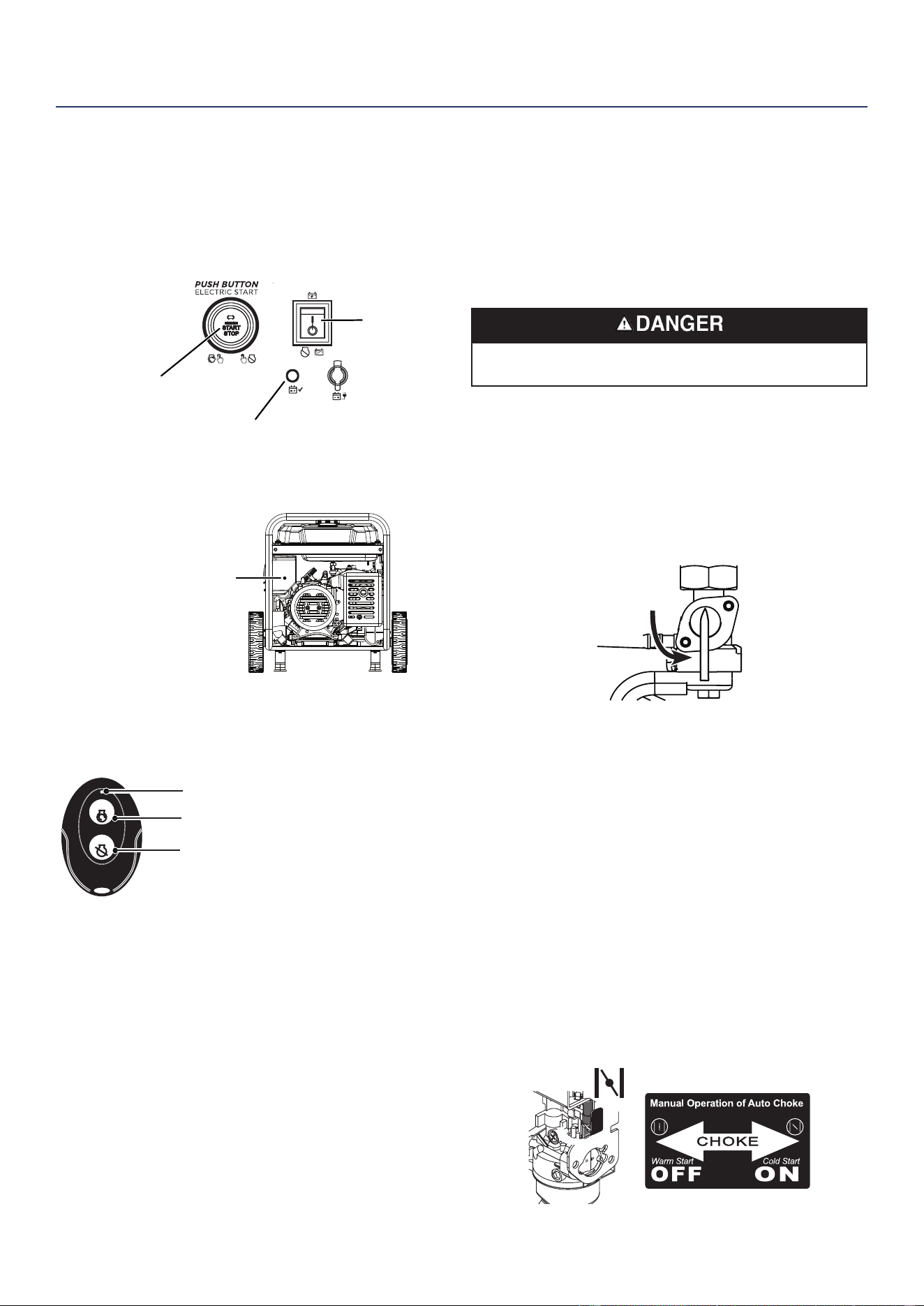
Westinghouse Outdoor Power Equipment, LLC | 67
APPAIRAGE DU DÉMARRAGE À DISTANCE
Piles de remplacement à distance: (2) CR2016
Si le porte-clés de démarrage à distance est remplacé ou
doit être ré-appairé au générateur, suivez cette procédure.
1. Mettez l’interrupteur de la batterie du générateur en
position ON. Le voyant d’alimentation s’allume.
Interrupteur
de batterie
Bouton poussoir START / STOP
Indicateur de puissance
2. Appuyez et maintenez le bouton d’appairage rouge sur
le côté du panneau de commande jusqu’à ce que le
bouton START/STOP s’allume.
Bouton d'appairage
3. Appuyez sur le bouton STOP du porte-clés et maintenez-
le enfoncé jusqu’à ce que l’éclairage du bouton START/
STOP s’éteigne. Relâchez le bouton. Le bouton START/
STOP s’allume une fois le bouton relâché.
START
STOP
Bouton ON
Voyant d'activation du porte-clés
Bouton OFF
4. Appuyez sur le bouton START de la télécommande
et maintenez-le enfoncé jusqu’à ce que l’éclairage du
bouton START/STOP s’éteigne. Relâchez le bouton.
Le bouton START/STOP s’allumera une fois le bouton
relâché.
5. Appuyez sur le bouton d’appairage sur le côté du
panneau de commande jusqu’à ce que l’éclairage du
bouton START/STOP s’éteigne. Relâchez le bouton.
6. Mettez l’interrupteur de la batterie du générateur en
position OFF. La télécommande est maintenant couplée.
AVANT DE DÉMARRER LE GÉNÉRATEUR
Vérier que:
• Le générateur est placé dans un endroit sûr et approprié.
• Le générateur se trouve sur une surface sèche, plane
et de niveau.
• Le moteur est rempli d’huile.
• Toutes les charges sont déconnectées.
Risque d’incendie et d’explosion. NE PAS déplacer ni
basculer le générateur pendant son fonctionnement.
DÉMARRAGE DU MOTEUR: ESSENCE
IMPORTANT: Ne jamais démarrer ou arrêter le générateur
avec des appareils électriques connectés
1. Vériez que le carburant est dans le réservoir d’essence.
2. Tournez le robinet du réservoir de carburant en position
ON.
ON
OFF
3. Poussez l’interrupteur de batterie en position ON.
4. Choisissez la méthode de départ:
a. Démarrage à distance: Appuyez et maintenez le
bouton START sur le porte-clés de démarrage à
distance pendant une seconde.
b. Démarrage par bouton-poussoir: Appuyez sur
le bouton START/STOP du moteur et maintenez-le
enfoncé pendant deux secondes.
c. Démarrage à recul: En cas de démarrage à froid,
fermez le starter en le déplaçant vers la droite
vers la poignée avant du générateur. Fermez
manuellement le starter si le moteur est froid.
Saisissez fermement et tirez lentement sur la
poignée de recul jusqu’à ce que vous ressentiez une
résistance accrue, puis tirez rapidement.
OPÉRATION

68 | Westinghouse Outdoor Power Equipment, LLC
ARRÊT DU MOTEUR
1. Éteignez et débranchez toutes les charges électriques
connectées.
IMPORTANT: Ne jamais démarrer ou arrêter le générateur
avec des appareils électriques connectés.
2. Laisser le générateur fonctionner sans charge pendant
plusieurs minutes pour stabiliser les températures
internes du moteur.
3. Poussez le commutateur Run/Stop en position Stop.
Remarque: Alternativement, si le générateur est rarement
utilisé, tournez le robinet du réservoir de
carburant en position OFF pour limiter le
carburant résiduel restant dans le bol du
otteur du carburateur. Le moteur s’arrête
lorsque le carburant dans le carburateur et la
conduite de carburant sont épuisés.
FRÉQUENCE D’UTILISATION
Si le générateur doit être utilisé de manière peu fréquente
ou intermittente (plus d’un mois avant la prochaine
utilisation), reportez-vous à la section Stockage de ce
manuel pour obtenir des informations sur la détérioration
du carburant.
DISJONCTEURS AC
Les disjoncteurs s’éteindront automatiquement s’il y a un
court-circuit ou une surcharge importante du générateur à
chaque prise.
Si un disjoncteur CA se coupe automatiquement, vériez
que l’appareil fonctionne correctement et qu’il ne dépasse
pas la capacité de charge nominale du circuit avant de
remettre le disjoncteur CA en MARCHE.
Appuyez pour réinitialiser
ON
OFF
Disjoncteurs
CAPACITÉ DU GÉNÉRATEUR
AVIS
Ne surchargez pas la capacité du générateur. Le
dépassement de la capacité en watts/ampérage du
générateur peut endommager le générateur et/ou les
appareils électriques qui y sont connectés.
Assurez-vous que le générateur peut fournir sufsamment
de watts continus (en fonctionnement) et de surtension (de
démarrage) pour les éléments que vous alimenterez en
même temps.
Les besoins de puissance totale (volts x ampères = watts)
de tous les appareils connectés doivent être pris en
compte. Les fabricants d’appareils et d’outils électriques
indiquent généralement les informations de classication
à côté du numéro de modèle ou de série.
Pour déterminer les besoins en énergie:
1. Sélectionnez les éléments que vous alimenterez en
même temps.
2. Additionnez les watts continus (courants) de ces
éléments. Il s’agit de la quantité d’énergie que le
générateur doit produire pour maintenir les éléments en
marche. Voir le tableau de référence de puissance à la
page suivante.
3. Estimez le nombre de watts de surtension (de démarrage)
dont vous aurez besoin. La puissance de surtension est
la courte rafale de puissance nécessaire pour démarrer
les outils ou appareils à moteur électrique tels qu’une
scie circulaire ou un réfrigérateur. Étant donné que
tous les moteurs ne démarrent pas en même temps,
les watts de surtension totaux peuvent être estimés en
ajoutant uniquement les éléments avec les watts de
surtension supplémentaires les plus élevés au total des
watts nominaux de l’étape 2.
Exemple:
Outil ou appareil
Watts
courants*
Watts de
départ*
Télévision (écran plat) 120 235
Réfrigérateur RV 180 600
Radio 200 0
Lumière (75 watts) 300 0
Machine à café 600 0
1400
Total
Watts
courants*
600
Watts de
démarrage
les plus
élevés*
Total des watts de fonctionnement 1400
Watts de démarrage les plus élevés + 600
Watts de démarrage totaux nécessaires 2000
* Les puissances indiquées sont approximatives. Vériez la puissance
réelle.
OPÉRATION

Westinghouse Outdoor Power Equipment, LLC | 69
GESTION DE L’ALIMENTATION
Pour prolonger la durée de vie du générateur et des
appareils connectés, soyez prudent lorsque vous ajoutez
des charges électriques au générateur. Il ne devrait y
avoir rien de connecté aux sorties du générateur avant
de démarrer le moteur. La façon correcte et sûre de
gérer l’alimentation du générateur consiste à ajouter des
charges séquentiellement comme suit:
1. Sans rien connecté au générateur, démarrez le moteur
comme décrit dans ce manuel.
2. Branchez et allumez la première charge, de préférence
la plus grande charge dont vous disposez.
3. Permettre à la sortie du générateur de se stabiliser
(le moteur tourne sans à-coups et l’appareil attaché
fonctionne correctement).
4. Branchez et allumez la charge suivante.
5. Encore une fois, laissez le générateur se stabiliser.
6. Répétez les étapes 4 et 5 pour chaque charge
supplémentaire.
Référence de puissance
Outil ou appareil
Watts
courants
estimés*
Watts de
démarrage
estimés*
Lumières à incandescence
(4 quantités x 75 watts)
300 0
Télévision (écran plat) 120 235
Pompe de puisard (1/3 hp) 800 1300
Réfrigérateur ou congélateur 700 2200
Pompe de puits(1/3 hp) 1000 2000
Radio 200 0
Percer (3/8”, 4 amps) 440 600
Scie circulaire
(Robuste, 7-1/4 “)
1400 2300
Scie à onglet (10 “) 1800 1800
Scie à table (10 “) 2000 2000
* Les puissances indiquées sont approximatives. Vériez la
puissance réelle.
RALLONGES
Risque d’asphyxie. Les rallonges fonctionnant
directement dans la maison augmentent le risque
d’intoxication au monoxyde de carbone par les
ouvertures. Si une rallonge qui entre directement dans
votre maison est utilisée pour alimenter des éléments
intérieurs, il existe un risque d’intoxication au monoxyde
de carbone pour les personnes à l’intérieur de la maison.
Utilisez toujours des détecteurs de monoxyde de
carbone alimentés par batterie et conformes aux normes
de sécurité UL 2034 en vigueur lors du fonctionnement
du générateur. Vériez régulièrement la batterie du (des)
détecteur (s).
Risque d’asphyxie. Lorsque vous utilisez le générateur
avec des rallonges, assurez-vous que le générateur est
situé dans un espace extérieur ouvert, loin des espaces
occupés avec l’évacuation dirigée vers l’extérieur.
Risque d’incendie et d’électrocution. N’utilisez jamais
de rallonges usées ou endommagées. Les rallonges
endommagées ou surchargées peuvent surchauffer,
présenter un arc et brûler, entraînant la mort ou des
blessures graves.
Avant de connecter un appareil CA ou un cordon
d’alimentation au générateur:
• Utilisez des rallonges à 3 broches, des outils et des
appareils mis à la terre, ou des outils et appareils à
double isolation.
• Assurez-vous que l’outil ou l’appareil est en bon état
de fonctionnement. Des appareils ou des cordons
d’alimentation défectueux peuvent créer un risque
d’électrocution.
• Assurez-vous que la puissance électrique de l’outil ou
de l’appareil ne dépasse pas la puissance nominale du
générateur ou de la prise utilisée.
OPÉRATION
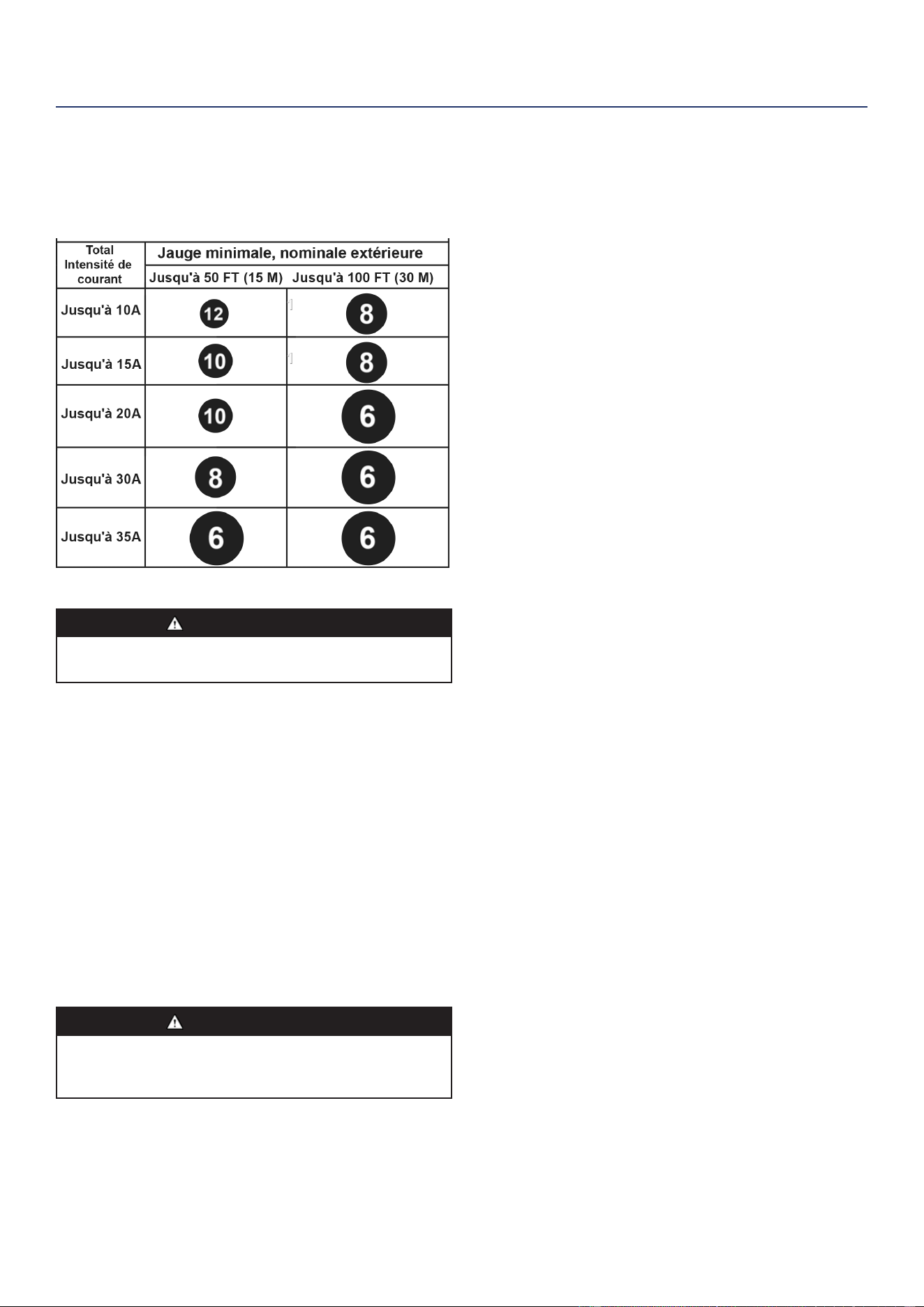
70 | Westinghouse Outdoor Power Equipment, LLC
OPÉRATION
DIMENSIONS DU CORDON D’EXTENSION
N’utilisez que des rallonges à 3 broches mises à la terre,
marquées pour une utilisation en extérieur et conçues
pour la charge électrique.
TRANSPORT
MISE EN GARDE
Risque de poids. Ayez toujours de l’aide pour soulever
le générateur.
• Laisser le générateur refroidir au moins 30 minutes
avant le transport.
• Replacez tous les couvercles de protection sur le
panneau de commande du générateur.
• Utilisez uniquement le châssis xe de la génératrice
pour soulever l’unité ou attacher des dispositifs de
retenue de charge tels que des cordes ou des sangles
d’arrimage. N’essayez pas de soulever ou de xer
le générateur en le tenant par l’un de ses autres
composants.
• Maintenez l’unité à niveau pendant le transport pour
minimiser la possibilité de fuite de carburant ou, si
possible, vidangez le carburant ou faites tourner le
moteur jusqu’à ce que le réservoir de carburant soit
vide avant le transport..
MISE EN GARDE
Risque d’incendie. Ne mettez pas le générateur à
l’envers et ne le placez pas sur le côté. Le carburant ou
l’huile peuvent fuir et endommager le générateur.
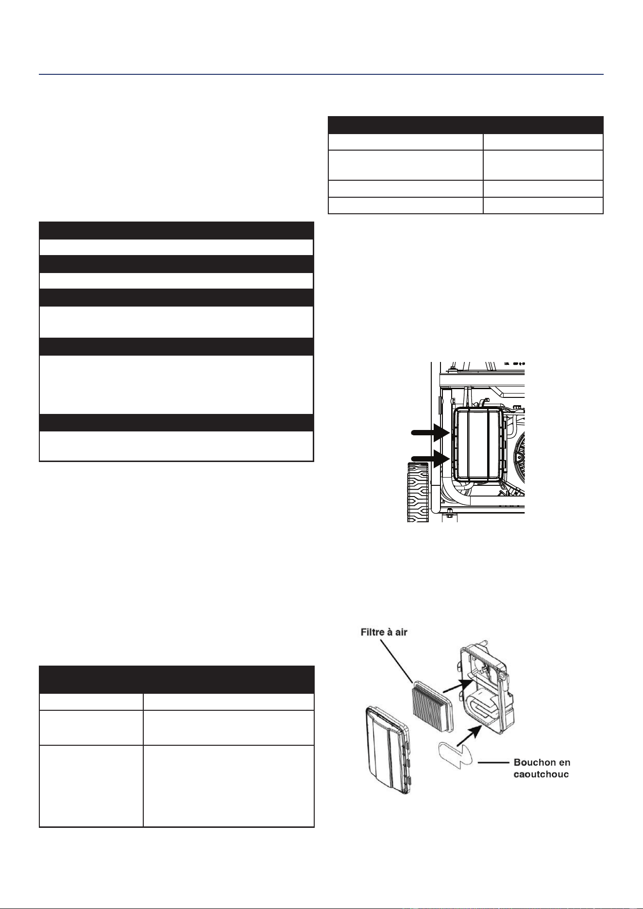
Westinghouse Outdoor Power Equipment, LLC | 71
ENTRETIEN
ENTRETIEN
CALENDRIER DE MAINTENANCE
Un entretien régulier améliorera les performances et
prolongera la durée de vie du générateur. Suivez les
intervalles horaires ou calendaires, selon la première
éventualité. Un entretien plus fréquent est nécessaire
lors du fonctionnement dans des conditions défavorables,
comme indiqué ci-dessous.
Avant chaque utilisation
Vérier l'huile moteur
Après les 25 premières heures ou le premier mois
Changez l'huile du moteur
Après 50 heures ou tous les 6 mois
Changer l’huile moteur
1
Filtre à air propre
2
Après 100 heures ou tous les 6 mois
Inspecter/nettoyer le pare-étincelles
Inspecter/nettoyer la bougie d’allumage
Entretien de la soupape de carburant
Inspecter/régler le jeu des soupapes
3
Après 300 heures ou chaque année
Remplacer la bougie
Remplacer le ltre à air
1
Changez l'huile tous les mois en cas de fonctionnement
sous forte charge ou à des températures élevées.
2
Nettoyez plus souvent dans des conditions sales ou
poussiéreuses. Remplacez le ltre à air s'il ne peut
pas être nettoyé correctement.
3
Il est recommandé que le service soit effectué par un
concessionnaire Westinghouse agréé.
RAPPELS D’ENTRETIEN
Les codes de rappel d’entretien seront afchés sur
l’afchage des données en fonction des heures de vie de
l’unité. Les codes de maintenance seront afchés jusqu’à
ce que l’appareil soit éteint. Reportez-vous à la section
Maintenance pour les procédures spéciques.
Code de
maintenance
Maintenance requise
P25 Changez l'huile du moteur
P50
• Changez l’huile du moteur
• Filtre à air propre
P100
• Changez l’huile du moteur
• Filtre à air propre
• Entretien de la soupape de
carburant
• Inspecter/régler le jeu des
soupapes
PIÈCES DE RECHANGE D’ENTRETIEN
La description Numéro d’article
Filtre à air 5941
Bouchon de vidange d'huile
rondelle d'écrasement
94007
Pare-étincelles 6790
Bougie d'allumage 97108 (F7TC)
ENTRETIEN DU FILTRE À AIR
Le ltre à air doit être nettoyé toutes les 50 heures
d’utilisation ou six mois (la fréquence doit être augmentée
si le générateur fonctionne dans un environnement
poussiéreux).
1. Placer le générateur sur une surface plane et laisser
refroidir le moteur pendant plusieurs minutes.
2. Relâchez les clips et retirez le couvercle du ltre à air.
3. Nettoyez le ltre à air avec de l’air comprimé. Remplacez
si endommagé.
4. Assurez-vous que le ltre à air et le capuchon en
caoutchouc sont correctement installés. Installez le
couvercle du ltre à air et xez-le en place avec les clips
du couvercle.
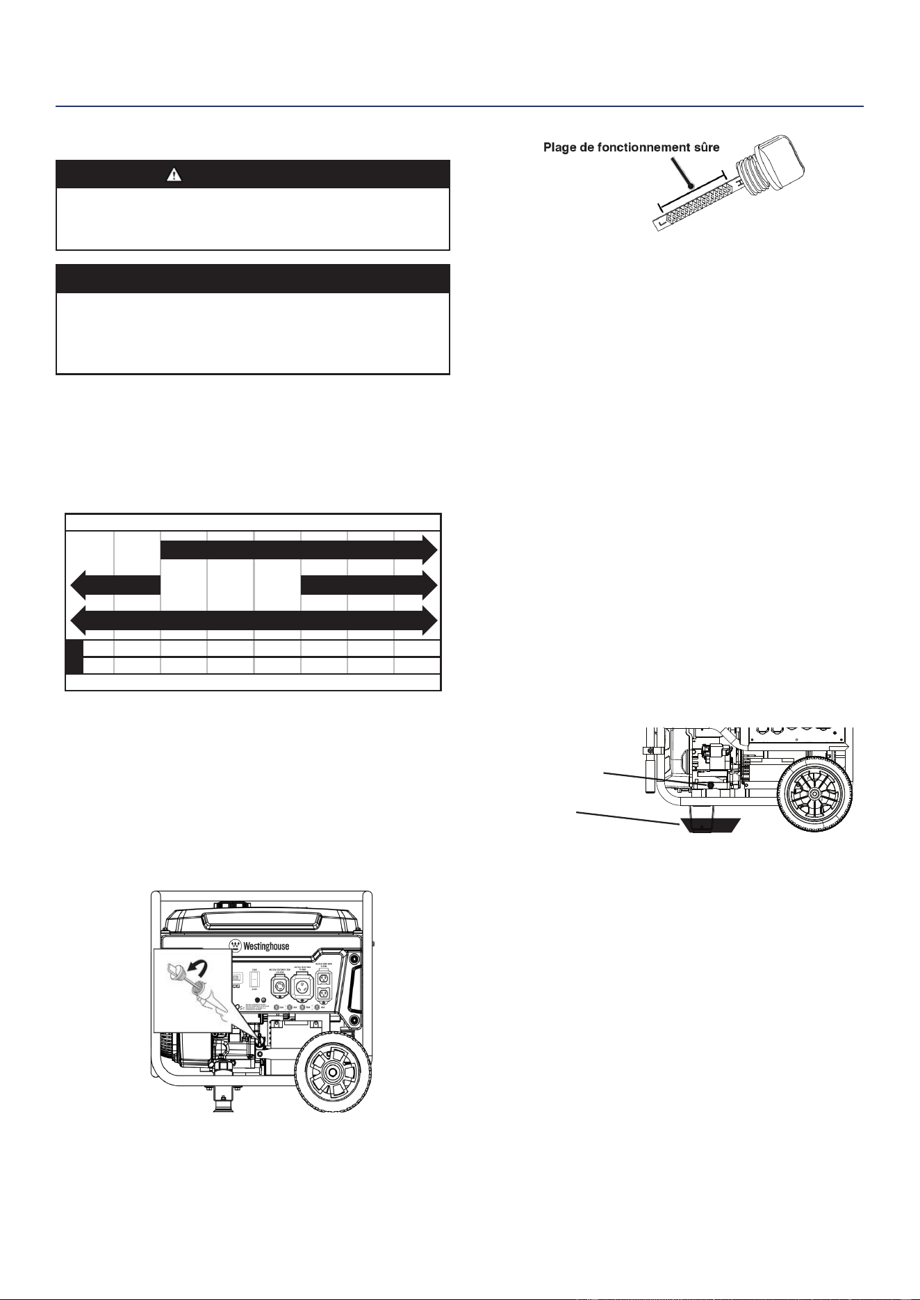
72 | Westinghouse Outdoor Power Equipment, LLC
CONTRÔLE DU NIVEAU D’HUILE MOTEUR
MISE EN GARDE
Évitez tout contact cutané avec l’huile moteur. Portez
des vêtements et des équipements de protection. Laver
toute la peau exposée avec du savon et de l’eau.
AVIS
Utilisez toujours l’huile moteur spéciée. Le fait de ne
pas utiliser l’huile moteur spéciée peut entraîner une
usure accélérée et/ou raccourcir la durée de vie du
moteur.
Lors de l’utilisation du générateur dans des conditions
extrêmes, sales, poussiéreuses ou par temps extrêmement
chaud, changez l’huile plus fréquemment.
La température de l’air ambiant affectera les performances
de l’huile moteur. Changer le type d’huile moteur utilisé en
fonction des conditions météorologiques.
-20 0 20 40 60
Température ambiante
Type d'huile moteur recommandé
80 100 120
-28.9
°F
°C -17.8 -6.7 4.4 15.6 26.7 37.8 48.9
10W-30
5W-30 Synthétique
10W-405W-30
Vériez le niveau d’huile moteur avant chaque utilisation
ou toutes les 8 heures de fonctionnement.
1. Placer le générateur sur une surface plane et laisser
refroidir le moteur pendant plusieurs minutes.
2. Avec un chiffon humide, nettoyez autour de la jauge
d’huile.
3. Retirez la jauge d’huile et essuyez la jauge.
4. Insérez la jauge dans le goulot de remplissage d’huile
sans la visser. Retirez la jauge et vériez que le niveau
d’huile est dans la plage de fonctionnement sécuritaire
entre les marques bas (L) et haut (H) sur la jauge.
5. Si le niveau est bas, ajoutez progressivement l’huile
moteur recommandée et revériez jusqu’à ce que le
niveau se situe entre les marques L et H de la jauge. Ne
pas trop remplir. Si au-dessus du repère H de la jauge,
vidangez l’huile pour réduire le niveau d’huile au repère
plein.
6. Remplacez la jauge d’huile et serrez à la main.
CHANGEMENT D’HUILE MOTEUR
Lorsque vous utilisez le générateur dans des conditions
sales ou par temps extrêmement chaud ou froid, changez
l’huile plus fréquemment. Changer l’huile pendant que le
moteur est encore chaud de fonctionnement.
1. Placer le générateur sur une surface plane et laisser
refroidir le moteur pendant plusieurs minutes.
2. Avec un chiffon humide, nettoyez autour de la jauge
d’huile. Retirez la jauge et essuyez.
3. Placez un carter d’huile (ou un récipient approprié) sous
le boulon de vidange d’huile.
4. À l’aide d’une clé de 10 mm, retirez le boulon de vidange
d’huile et laissez l’huile s’écouler.
Carter d'huile
Boulon de vidange
5. Installez le boulon de vidange d’huile et serrez
fermement.
Remarque: Une nouvelle rondelle d’écrasement du
bouchon de vidange d’huile est recommandée
à chaque vidange d’huile.
6. Versez lentement l’huile dans le goulot de remplissage
d’huile jusqu’à ce que le niveau d’huile se situe entre les
marques L et H de la jauge. Arrêtez-vous fréquemment
pour vérier le niveau d’huile. Ne pas trop remplir.
Capacité d’huile maximale: 0,74 quart (0,7 litre)
7. Installez la jauge d’huile et serrez à la main.
ENTRETIEN
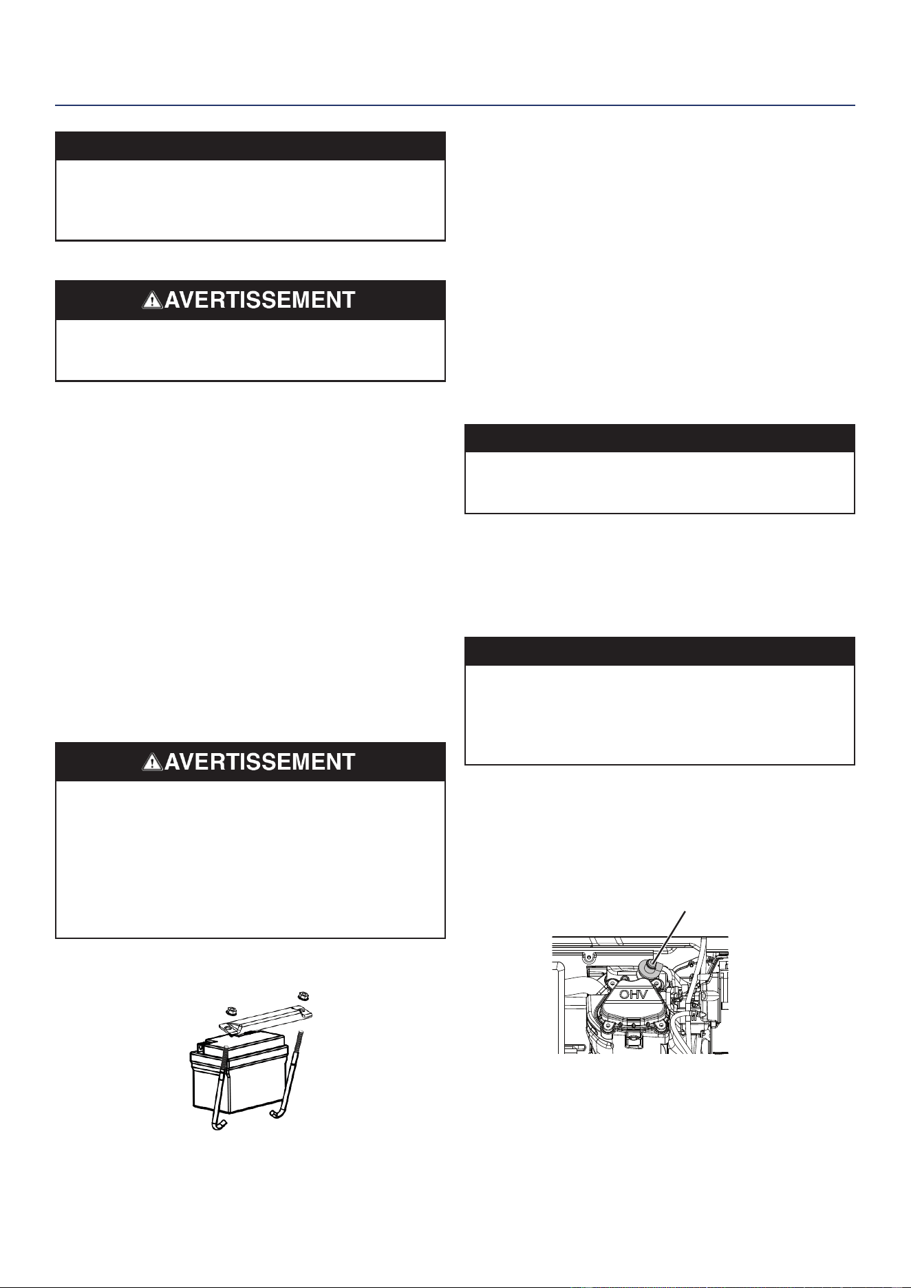
Westinghouse Outdoor Power Equipment, LLC | 73
AVIS
Ne polluez pas. Suivez les directives de l’EPA ou
d’autres organismes gouvernementaux pour l’élimination
appropriée des matières dangereuses. Consultez les
autorités locales ou les installations de remise en état.
ENTRETIEN DE LA BATTERIE
Risque d’explosion. Les batteries émettent des gaz
explosifs pendant la charge. Éloignez le feu et les
étincelles.
La batterie livrée avec le générateur a été complètement
chargée. Une batterie peut perdre une partie de sa charge
lorsqu’elle n’est pas utilisée pendant de longues périodes.
Remarque: Une fois démarré, le générateur chargera la
batterie après 30 à 60 minutes d’utilisation.
Le chargeur d’entretien inclus peut rester connecté et
conservera la batterie pendant une période indénie. Un
voyant rouge sur le chargeur indique que la charge est en
cours. Un voyant vert indique que la charge est terminée.
Charger dans un endroit sec.
1. Branchez le chargeur dans le port de charge de la
batterie sur le panneau de commande.
2. Branchez l’extrémité de la prise murale du chargeur de
batterie dans une prise murale de 120 volts CA.
REMPLACEMENT DE LA BATTERIE
Gardez les bornes de la batterie couvertes en tout temps.
Le générateur est livré avec une batterie au lithium-ion
(Li-Ion). Les bornes positives et négatives métalliques
exposées peuvent court-circuiter lorsqu’elles entrent
en contact avec des objets métalliques, enammant
les matériaux internes de la cellule et expulsant de
force le contenu en feu, entraînant des incendies, des
explosions, des blessures graves et même la mort.
1. Desserrez et retirez les boulons xant la plaque de
maintien de la batterie et retirez la plaque.
2. Débranchez les ches à connexion rapide et retirez la
batterie de l’unité.
3. Débranchez les ls du câble à déconnexion rapide de
la batterie.
4. Sur la batterie de remplacement, connectez le câble
de connexion rapide blanc (-) à la borne négative de
la batterie. Faites glisser la gaine en caoutchouc sur le
matériel de connexion.
5. Connectez le câble de connexion rapide rouge (+) à la
borne positive de la batterie. Faites glisser la gaine en
caoutchouc sur le matériel de connexion.
6. Installez la batterie dans le générateur. Réinstallez la
plaque de maintien de la batterie et serrez les boulons.
7. Branchez la che à connexion rapide.
AVIS
Débarrassez-vous de la batterie usagée conformément
aux directives établies par votre gouvernement local ou
national.
MAINTENANCE DES BOUGIES
Inspectez et nettoyez la bougie d’allumage toutes les
100 heures d’utilisation ou six mois. Remplacez la bougie
d’allumage après 300 heures d’utilisation ou chaque
année.
AVIS
Utilisez toujours la bougie d’allumage Westinghouse
OEM ou compatible sans résistance. L’utilisation d’une
bougie d’allumage de type résistance peut entraîner un
ralenti irrégulier, des ratés d’allumage ou peut empêcher
le moteur de démarrer.
1. Placer le générateur sur une surface plane et laisser
refroidir le moteur.
2. Retirez le soufet de bougie d’allumage en tirant
fermement le soufet d’allumage directement loin du
moteur.
Bougie d'allumage
3. Nettoyez la zone autour de la bougie.
4. Retirez la bougie d’allumage avec la clé à douille de
bougie incluse.
ENTRETIEN
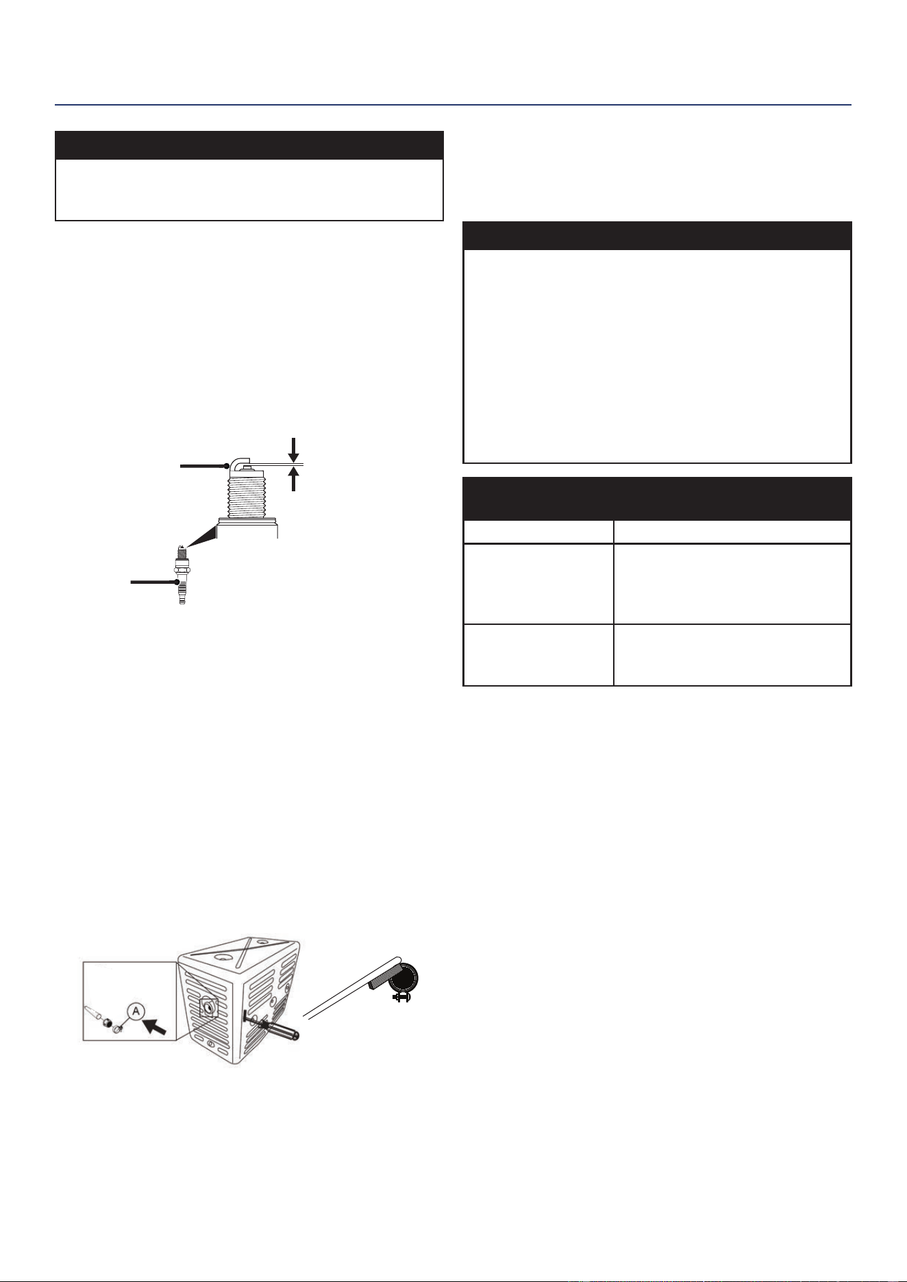
74 | Westinghouse Outdoor Power Equipment, LLC
ENTRETIEN
AVIS
N’appliquez jamais de charge latérale et ne déplacez
jamais la bougie d’allumage latéralement lors du retrait
de la bougie.
5. Inspectez la bougie d’allumage. Remplacez-les si les
électrodes sont piquées, brûlées ou si l’isolant est
ssuré. Utilisez uniquement une che de remplacement
recommandée.
6. Mesurez l’écartement des électrodes de la bougie avec
une jauge d’épaisseur à l. Si nécessaire, corrigez
l’écart en pliant soigneusement l’électrode latérale.
Ecartement électrode bougie:
0.024 – 0.032 in. (0.60 – 0.80 mm)
0.024 - 0.032 in.
(0.60 - 0.80 mm)
Isolant
Électrode latérale
7. Installez soigneusement la bougie à la main, puis serrez
de 3/8 à 1/2 tour supplémentaire avec la clé à bougie.
8. Fixez le soufet de bougie.
SERVICE DE PARE-ÉTINCELLES
Laissez le silencieux refroidir complètement avant de
réparer le pare-étincelles. Vériez et nettoyez le pare-
étincelles toutes les 100 heures d’utilisation ou six mois.
Le fait de ne pas nettoyer le pare-étincelles entraînera une
dégradation des performances du moteur.
1. Placer le générateur sur une surface plane.
2. Faites glisser le tournevis dans la fente latérale et retirez
le collier de serrage (A) du pare-étincelles. Retirez
l’ensemble pare-étincelles.
3. Retirez soigneusement les dépôts de carbone de l’écran
pare-étincelles avec une brosse métallique. Le pare-
étincelles doit être exempt de cassures et de déchirures.
Remplacez le pare-étincelles s’il est endommagé.
4. Réinstaller le pare-étincelles.
ESPACE DE RANGEMENT
Une préparation de stockage appropriée est nécessaire
pour un fonctionnement sans problème et la longévité du
générateur.
AVIS
L’essence stockée pendant aussi peu que 30 jours
peut se détériorer, provoquant une accumulation de
gomme, de vernis et de corrosion dans les conduites de
carburant, les passages de carburant et le moteur. Cette
accumulation corrosive restreint le débit de carburant,
ce qui peut empêcher le moteur de démarrer après
une période de stockage prolongée. L’utilisation d’un
stabilisateur de carburant augmente considérablement
la durée de stockage de l’essence. Il est recommandé
d’utiliser à plein temps le stabilisateur de carburant.
Suivez les instructions d’utilisation du fabricant.
TEMPS DE
STOCKAGE
PROCÉDURE RECOMMANDÉE
Moins de 1 mois Aucun service requis.
2 à 6 mois
Faites le plein d'essence fraîche
et ajoutez du stabilisateur
d'essence. Vidangez le bol du
otteur du carburateur.
6 mois ou plus
Vidanger le réservoir de
carburant et la cuve du otteur
du carburateur.
STOCKAGE À COURT TERME
• Laisser le générateur refroidir au moins 30 minutes
avant de le ranger.
• Replacez tous les couvercles de protection sur le
panneau de commande du générateur.
• Essuyez le générateur avec un chiffon humide.
Nettoyez tous les débris des évents de refroidissement
du silencieux.
• Entreposez le générateur dans un endroit bien ventilé
et sec à l’écart des étincelles, des ammes nues,
des veilleuses, de la chaleur et d’autres sources
d’inammation telles que les zones avec un moteur
électrique produisant des étincelles ou là où des outils
électriques sont utilisés.
• Avec le moteur et le système d’échappement froids
et toutes les surfaces sèches, couvrez le générateur
pour empêcher la poussière d’entrer. N’utilisez pas de
feuille de plastique comme cache anti-poussière. Les
matériaux non poreux retiennent l’humidité et favorisent
la rouille et la corrosion.
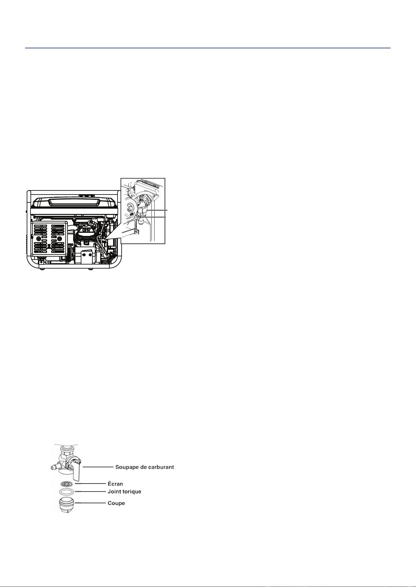
Westinghouse Outdoor Power Equipment, LLC | 75
STOCKAGE À LONG TERME
Même un carburant correctement stabilisé peut laisser des
résidus et provoquer de la corrosion s’il est laissé à long
terme. Si vous stockez le générateur pendant deux à six
mois, vidangez le bol du otteur pour éviter l’accumulation
de gomme et de vernis dans le carburateur.
VIDANGE DU FLOTTEUR
1. Mettez le robinet du réservoir de carburant en position
OFF.
2. Localisez la vis de vidange au bas du bol du otteur du
carburateur.
Vis de vidange
Bol à flotteur
3. Placez un réservoir d’essence approprié sous la vis de
vidange pour récupérer le carburant vidangé.
4. Desserrez la vis de vidange du bol du otteur et laissez
le carburant s’écouler. Serrez la vis de vidange du bol
du otteur.
ENTRETIEN DE LA SOUPAPE DE CARBURANT
Le robinet de carburant est équipé d’une coupelle à
sédiments de carburant, d’un tamis et d’un joint torique. Le
robinet de carburant ne nécessite pas d’entretien si l’unité
est correctement entretenue avec du carburant frais et
propre. Si un dépannage lié au carburant est nécessaire,
effectuez la maintenance de la vanne de carburant.
1. Tournez le robinet de carburant en position OFF.
2. Retirez la coupelle à sédiments du robinet de carburant.
Retirez le joint torique et l’écran.
3. Lavez la coupelle à sédiments, le joint torique et le
tamis dans un solvant ininammable. Séchez-les
soigneusement.
4. Placez la crépine et le joint torique dans le robinet de
carburant. Installez la coupelle à sédiments et serrez
fermement.
5. Tournez le robinet de carburant en position ON et vériez
s’il y a des fuites. Remplacez le robinet de carburant en
cas de fuite.
VIDANGE DU RÉSERVOIR DE CARBURANT
Si vous entreposez le générateur pendant plus de six
mois, vidangez le réservoir de carburant pour éviter la
séparation, la détérioration et les dépôts de carburant
dans le système de carburant.
1. Dévissez le bouchon du réservoir de carburant. Retirez
le ltre à carburant en le comprimant légèrement tout en
le retirant du réservoir.
2. À l’aide d’une pompe à essence disponible dans le
commerce (non incluse), siphonnez l’essence du
réservoir de carburant dans un réservoir d’essence
approuvé. NE PAS utiliser de pompe électrique.
3. Réinstaller le ltre à carburant et le bouchon du réservoir
de carburant.
4. Démarrez le générateur et laissez-le fonctionner jusqu’à
ce que le moteur du générateur s’arrête.
5. Poussez le commutateur Run/Stop en position Stop.
6. Retirez la bougie.
7. Mettez une cuillère à café d’huile moteur dans le
cylindre et tirez sur la poignée de recul jusqu’à ce qu’une
résistance se fasse sentir. Dans cette position, le piston
remonte sur sa course de compression et les deux
soupapes sont fermées. Le stockage du moteur dans
cette position aidera à prévenir la corrosion interne.
Remettez doucement la poignée de recul.
8. Réinstaller la bougie d’allumage. Laissez le soufet
de bougie débranché pour éviter tout démarrage
accidentel.
ENTRETIEN
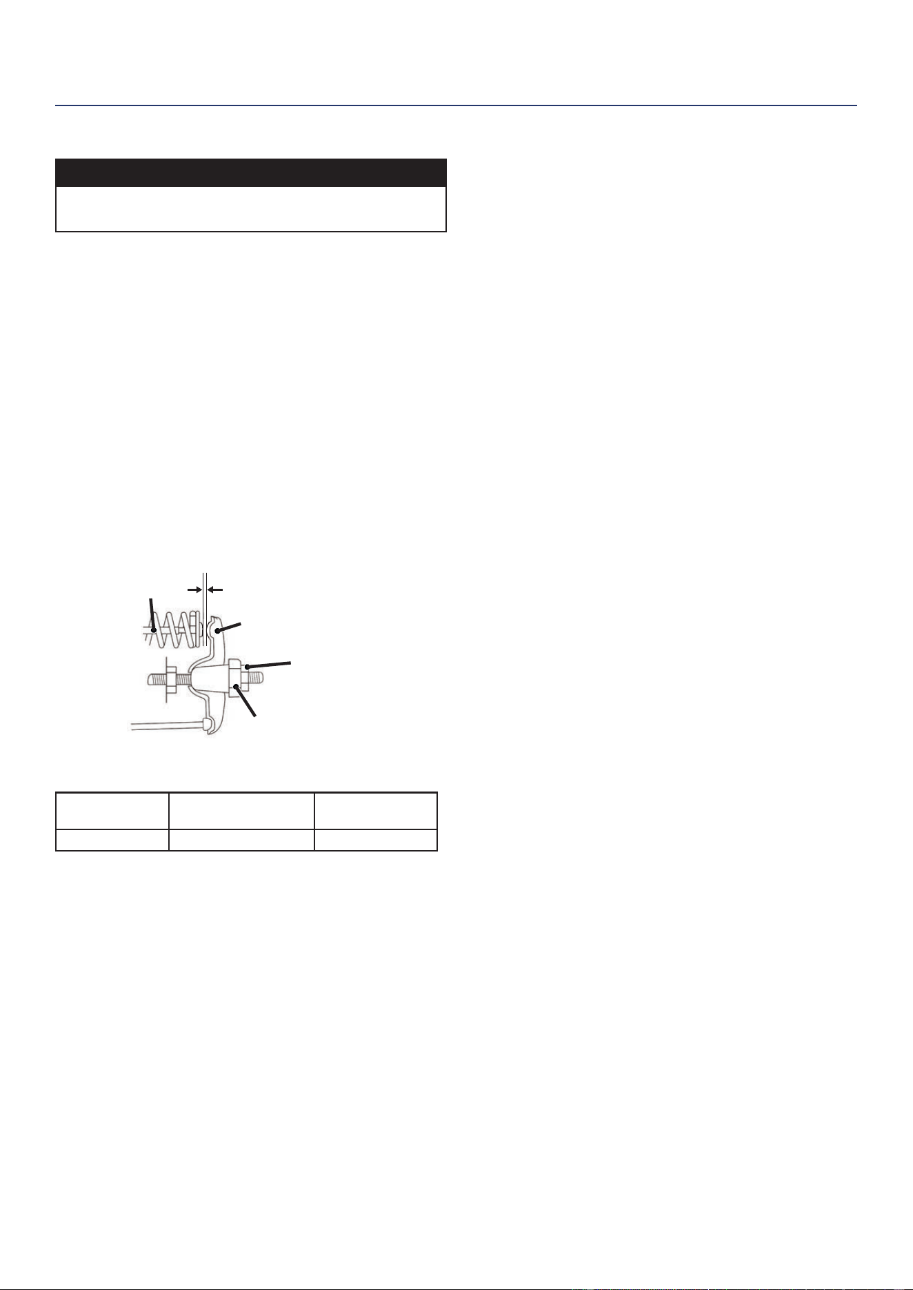
76 | Westinghouse Outdoor Power Equipment, LLC
LE JEU DES SOUPAPES
REMARQUER
Le contrôle et le réglage du jeu des soupapes doivent
être effectués lorsque le moteur est froid.
1. Retirez le couvercle du culbuteur et retirez soigneusement
le joint. Si le joint est déchiré ou endommagé, il doit être
remplacé.
2. Retirez la bougie d’allumage pour que le moteur puisse
tourner plus facilement.
3. Faites tourner le moteur jusqu’au point mort haut (PMH)
en tirant lentement sur la poignée de recul. En regardant à
travers le trou de la bougie, le piston doit être en haut (les
deux soupapes sont fermées).
4. Les deux culbuteurs doivent être desserrés au PMH sur
la course de compression. Si ce n’est pas le cas, faites
tourner le moteur à 360 °.
5. Insérez une jauge d’épaisseur entre le culbuteur et la tige
de soupape pour mesurer le jeu des soupapes.
écrou de réglage
du pivot
Tige de valve
Culbuteur
Pivot de culbuteur
Soupape
d'échappement
Soupape
d’admission
Le jeu des
soupapes
0.0031 – 0.0047 in
(0.08 – 0.12 mm)
0.0051 – 0.0067 in
(0.13 – 0.17 mm)
Couple 8-12 N•m 8-12 N•m
6. Si un réglage est nécessaire, maintenez le pivot du
culbuteur et desserrez l’écrou de réglage du pivot.
7. Tournez le pivot du culbuteur pour obtenir le jeu spécié.
Maintenez le pivot du culbuteur et resserrez l’écrou de
réglage du pivot au couple spécié.
Couple: 106 pouces-livres (12 N • m)
8. Exécutez cette procédure pour l’autre vanne.
9. Installez le joint, le couvercle du culbuteur et la bougie
d’allumage.
ENTRETIEN

Westinghouse Outdoor Power Equipment, LLC | 77
DÉPANNAGE
DÉPANNAGE
DÉPANNAGE
PROBLÈME CAUSE POSSIBLE CORRECTION
Le moteur ne démarre pas
En panne d’essence. Ravitailler.
Mauvais carburant, générateur stocké sans traitement ni vidange
d’essence, ou plein d’essence.
Videz le réservoir de carburant. Faites le plein
d’essence fraîche.
Filtre à air sale. Nettoyez le ltre à air.
Le niveau d’huile moteur bas a arrêté le générateur.
Si le voyant de niveau d’huile bas est allumé,
tournez le commutateur de batterie en
position OFF. Ajoutez de l’huile moteur.
Bougie d’allumage mouillée de carburant (moteur noyé).
Attendez cinq minutes. Mettez l’interrupteur
de la batterie en position OFF. Tirez la
poignée de recul rapidement plusieurs fois.
Si le générateur ne démarre pas, retirez la
bougie et séchez.
Bougie d’allumage défectueuse, encrassée ou mal espacée. Écartez ou remplacez la bougie. Réinstaller.
Filtre à carburant obstrué, dysfonctionnement du système
d’alimentation, défaillance de la pompe à carburant,
dysfonctionnement d’allumage, soupapes bloquées, etc.
Contactez le service à la clientèle de
Westinghouse sans frais au 1 (855) 944-
3571.
Starter partiellement ouvert ou fermé en raison d’une batterie
faible ou déconnectée.
Réglez manuellement le starter. Voir la
section Maintenance.
Le moteur démarre, puis
s’arrête
En panne d’essence. Ravitailler.
Niveau d’huile moteur incorrect. Vériez le niveau d’huile moteur.
Filtre à air sale. Nettoyez le ltre à air.
Carburant contaminé.
Videz le réservoir de carburant. Faites le plein
d’essence fraîche.
Interrupteur de bas niveau d’huile défectueux.
Contactez le service à la clientèle de
Westinghouse sans frais au 1 (855) 944-
3571.
Mauvais carburant, générateur stocké sans traitement ni vidange
d’essence, ou plein d’essence.
Videz le réservoir de carburant. Faites le plein
d’essence fraîche.
Filtre à carburant obstrué, dysfonctionnement du système
d’alimentation, défaillance de la pompe à carburant,
dysfonctionnement d’allumage, soupapes bloquées, etc.
Contactez le service à la clientèle de
Westinghouse sans frais au 1 (855) 944-
3571.
Le moteur tourne mal
ou tourbillonne lors de
l’application de la charge
Filtre à air sale. Nettoyez le ltre à air.
Générateur surchargé. Débranchez certains appareils.
Outil électrique ou appareil défectueux.
Remplacez ou réparez l’outil ou l’appareil.
Arrêtez et redémarrez le moteur.
Filtre à carburant obstrué, dysfonctionnement du système
d’alimentation, défaillance de la pompe à carburant,
dysfonctionnement d’allumage, soupapes bloquées, etc.
Contactez le service à la clientèle de
Westinghouse sans frais au 1 (855) 944-
3571.
Pas d’alimentation aux
prises CA
La LED OUTPUT READY est éteinte et la LED OVERLOAD est
allumée.
Vériez la charge CA. Arrêtez et redémarrez
le moteur.
Vériez l’entrée d’air. Arrêtez et redémarrez
le moteur.
Disjoncteur/s CA déclenché.
Vériez les charges CA et réinitialisez le ou
les disjoncteurs.
Outil électrique ou appareil défectueux.
Remplacez ou réparez l’outil ou l’appareil.
Arrêtez et redémarrez le moteur.
Générateur défectueux.
Contactez le service à la clientèle de
Westinghouse sans frais au 1 (855) 944-
3571.
dépannage

™ & © 2021 Westinghouse Electric Corporation
© 2021 Westinghouse Outdoor Power Equipment, LLC All Rights Reserved.
WGen5300 Rev01
121646 Rev04 09/21