CamView
TM
IP Pro- X
Series Testers
USER MANUAL

2 www.triplett.com UM-8075
Contents
Introduction .................................................................................................. 3
Safety Information ........................................................................................ 3
Descriptions .................................................................................................. 4--8
Function Overview ........................................................................................ 9-12
Basic Operation - Installing, Charging Battery and Power Up ....................... 12-14
IP Camera Testing ...................................................................................... 15-28
Analog Camera Testing .............................................................................. 29-33
Network Tools ............................................................................................. 34-38
Wireless Test ............................................................................................... 38-43
Cable TDR Test ............................................................................................ 43-45
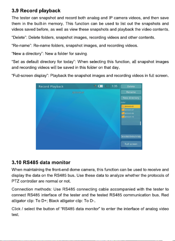
Record Playback .......................................................................................... 45
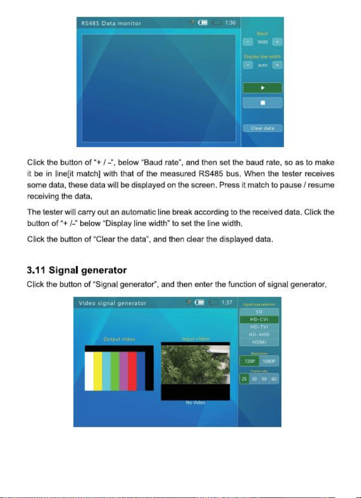
RS485 Data Monitor ................................................................................... 45
Signal Generator ........................................................................................ 46-47
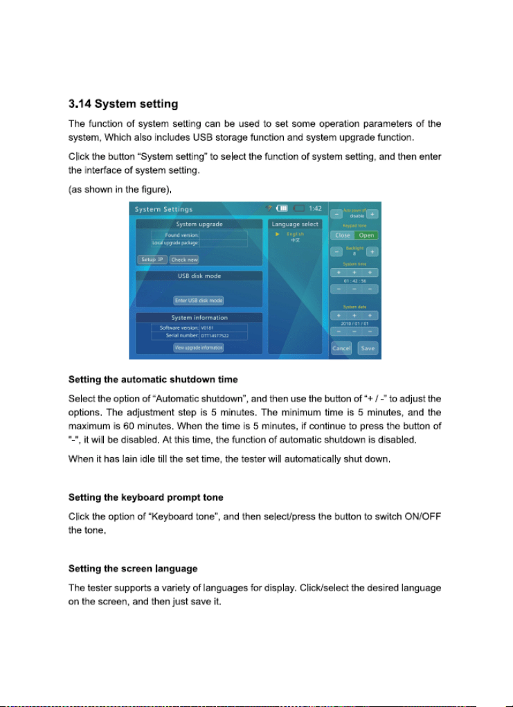
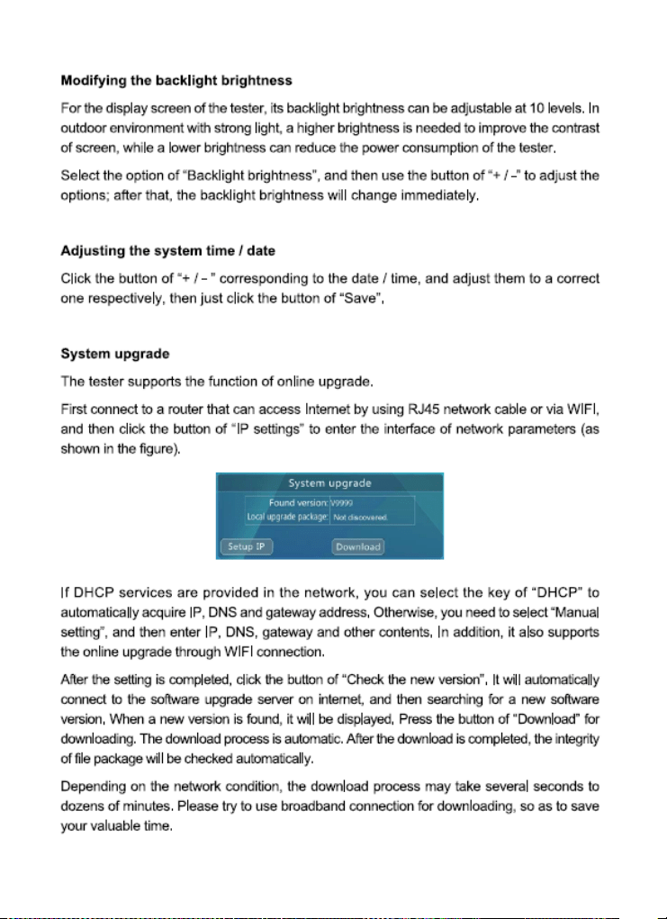
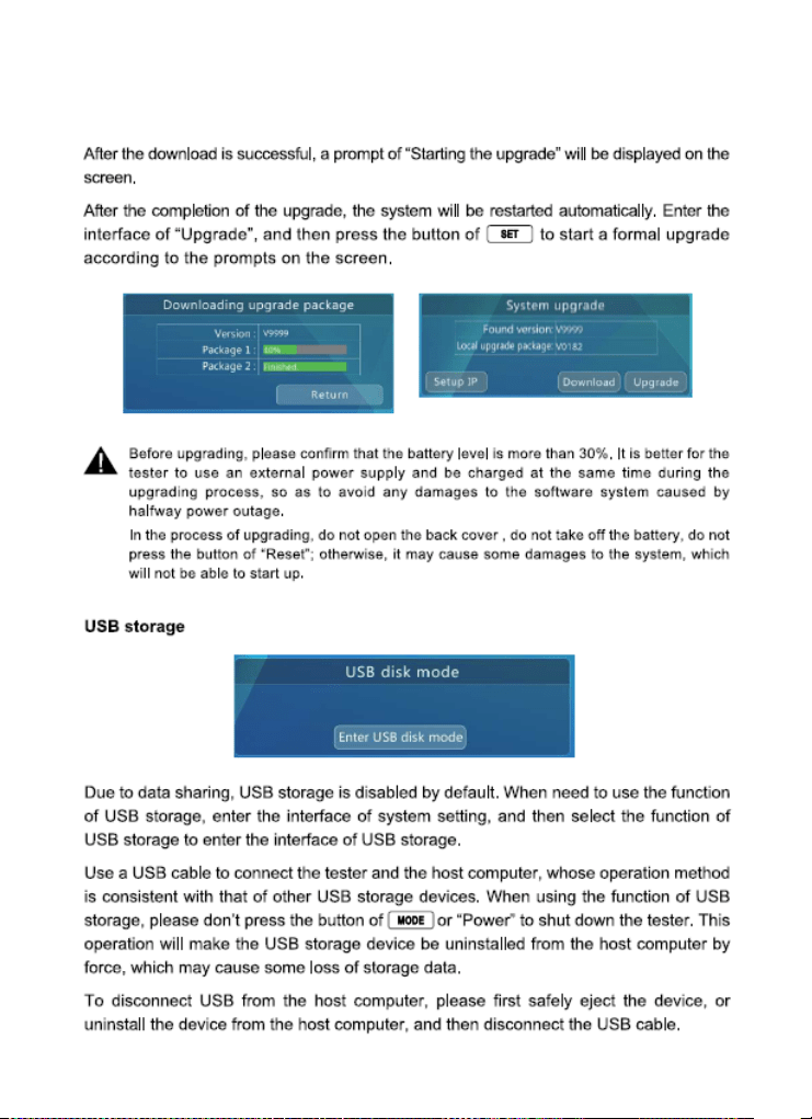
System Settings ........................................................................................... 48-50
Audio Test ................................................................................................... 51
Using PoE to Power Device ......................................................................... 51
Using 12V/2A to Power Camera ................................................................ 51
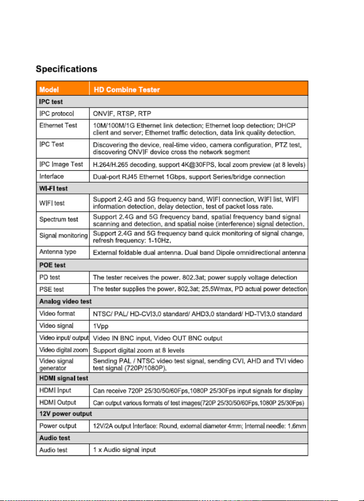
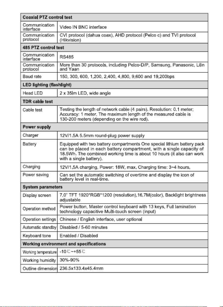
Specifications .............................................................................................. 52-54
About Triplett .............................................................................................. 55
Accessories (In the Box):
One each of the following items are included in the package: Camview IP Pro-X
Tester, Lanyard ,Carrying Case, Network Cable ,BNC Cable RS485 Cable
12V/2A Power DC Charger ,(2) “Quick-Connect Power” Batteries, User Manual
(UM-8075)

3 www.triplett.com UM-8075
Introduction
Thank you for purchasing the Triplett CamView™ IP Pro-X. Please read the
manual carefully before using the product.
To assure safe use of this product, please read the section on Safety carefully, and
observe any Cautions or Warnings posted there and throughout this manual.
Please keep this manual for future reference.
SAFETY INFORMATION
• Comply with all local electrical safety and electromagnetic compatibility
rules and regulations when using this device.
• Use original accessories with this equipment to avoid possible damage
caused from unapproved accessories.
• Accessories supplied are only intended for use with this product. Use with
other products or for other purposes is not recommended.
• Do not expose the product to rain, liquids, or excessive moisture as product
damage may occur.
• Do not expose or use the product in dusty or highly particulate environments.
• Avoid dropping the product or subjecting it to physical shock or high vibrations.
• Avoid leaving the product unattended while recharging it. Charging time should
not exceed 8 hours. If the battery becomes hot, disconnect power immediately.
• Do not use the product in an environment containing flammable gases
• Do not attempt to disassemble the product. There are no user serviceable
parts inside and product damage can occur. Contact Triplett customer
service if the unit does not function properly.
• Do not use the product in environments with strong electromagnetic fields.
• Do not handle or operate the product with wet hands.
• Do not use strong detergents or solvents for cleaning the product. Wipe off dirt
with a soft dry cloth, or a soft cloth slightly moistened with water or mild cleaner
4 www.triplett.com UM-8075
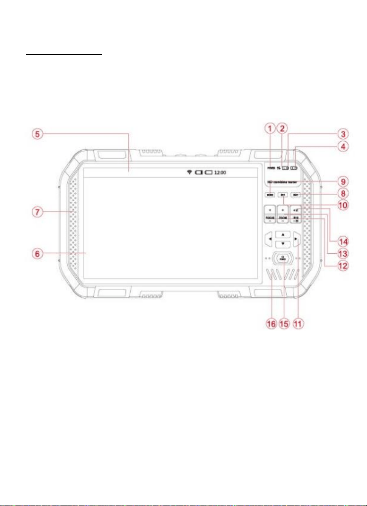
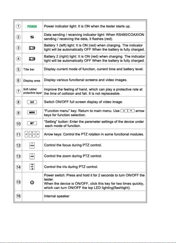
Descriptions
Front – Faceplate and Keypad
5 www.triplett.com UM-8075
6 www.triplett.com UM-8075
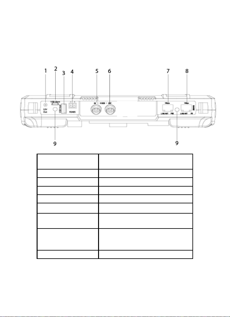
Top Side
1
12V/2A Output Jack (4mm, Inner Pin
1.65mm)
2
Micro-USB Jack (PC connection)
3
USB Host Extension Interface
4
RS-485 Control Output (for PTZ Control)
5
Analog Video Input BNC Connector
6
Analog Video Output BNC Connector
7
Network Port 1 (Blue) with PoE Supply
Output Function
8
Network Port 1 (Green) with PoE Supply
Input Detection & Device Charging
Input Port
9
LED Flash/Blink Indicator
7 www.triplett.com UM-8075
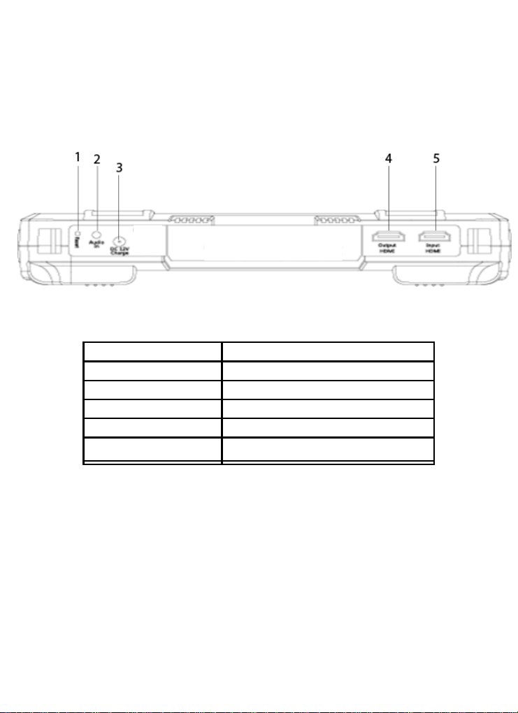
Bottom Side
1
RESET Button
2
Audio Input Jack (3.5mm)
3
DC12V Charging Input Jack
4
HDMI Output
5
HDMI Input
6
Analog Video Output BNC Connector
8 www.triplett.com UM-8075
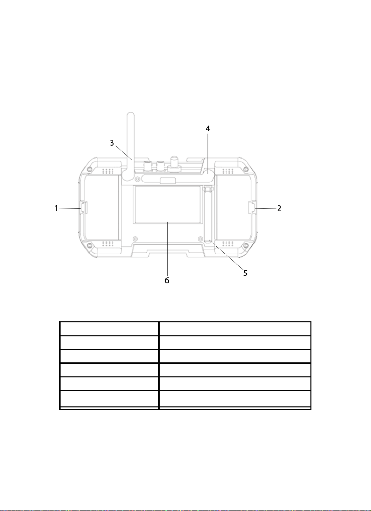
Back Side
1
Right #2 Battery Cover Latch
2
Left #1 Battery Cover Latch
3
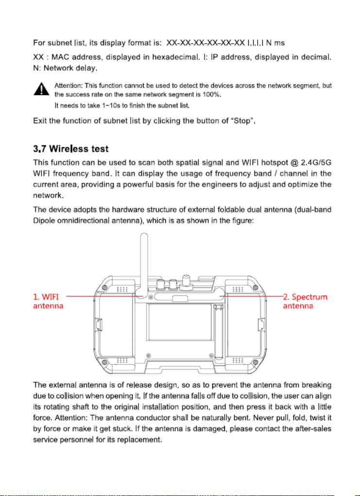
WiFi Antenna (Foldable)
4
Spectrum Antenna (Foldable)
5
Tester Tilt Stand
6
Circuit Heatsink

9 www.triplett.com UM-8075
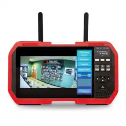
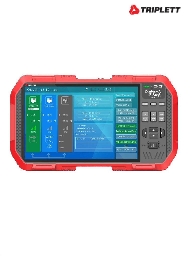
Function Overview
ONVIF IP Camera Test
The Tester will guide you through a step-by-step
process to test the functionality of IP cameras,
whether they are connected to an existing network or
directly attached to the Tester. These steps include:
Step 1: Testing Ethernet connections, POE, IP
settings, DHCP status/request, or providing
DHCP service to a directly connected camera;
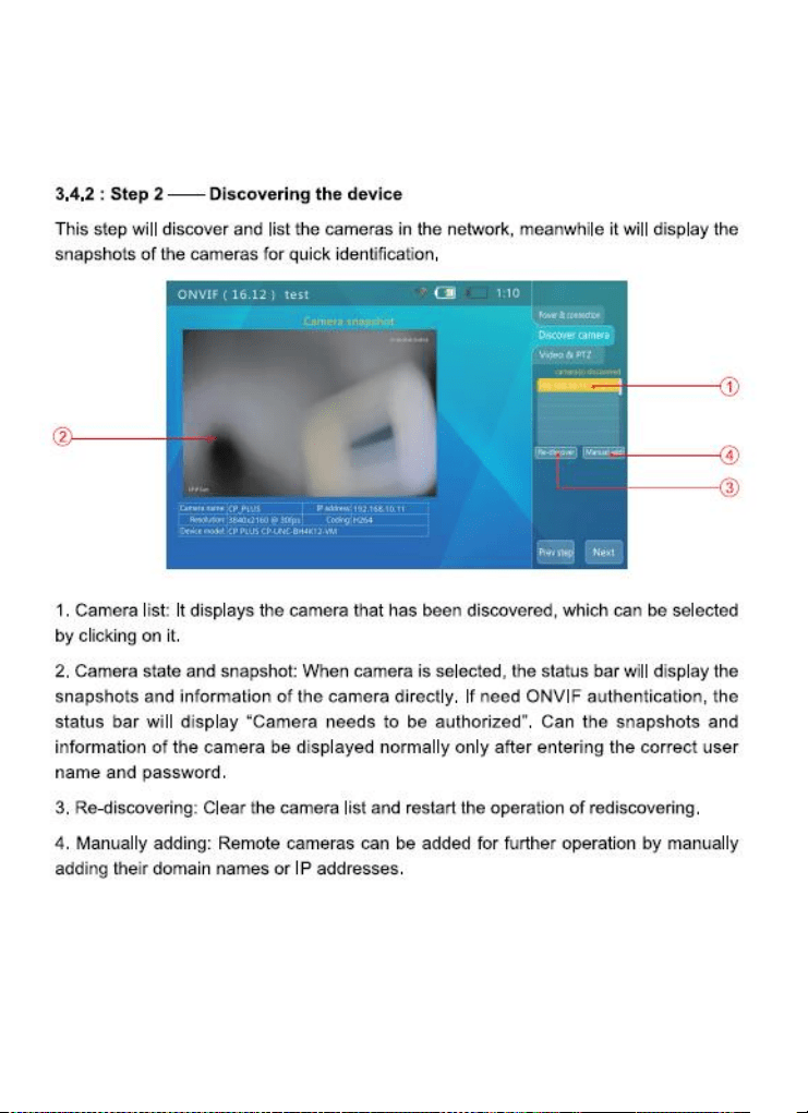
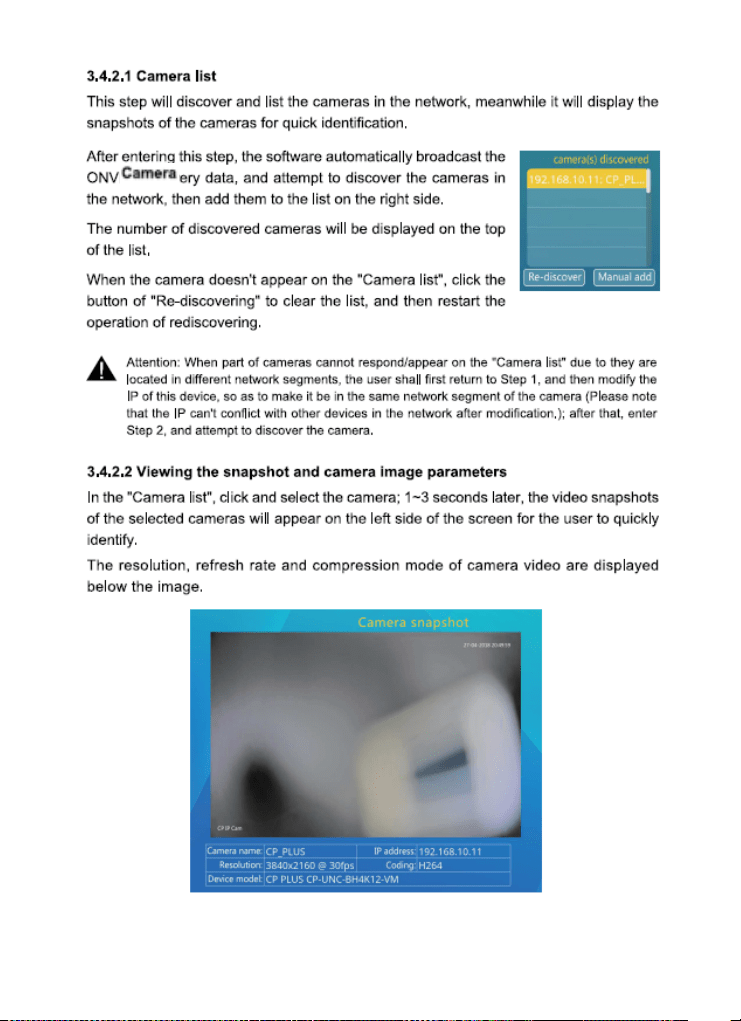
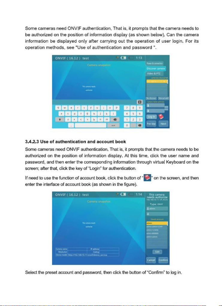
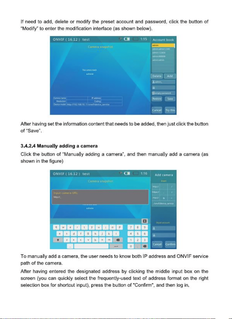
Step 2: Discovering camera(s), accessing camera
settings, ONVIF report generation, showing a
snapshot from the currently selected camera;
and
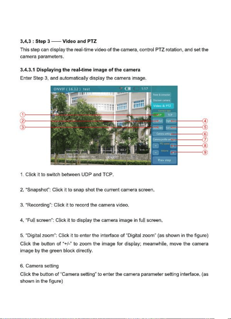
Step 3: Displaying live video from the camera,
profile/stream settings, and controlling the
camera’s PTZ functions (if camera is capable of
PTZ).
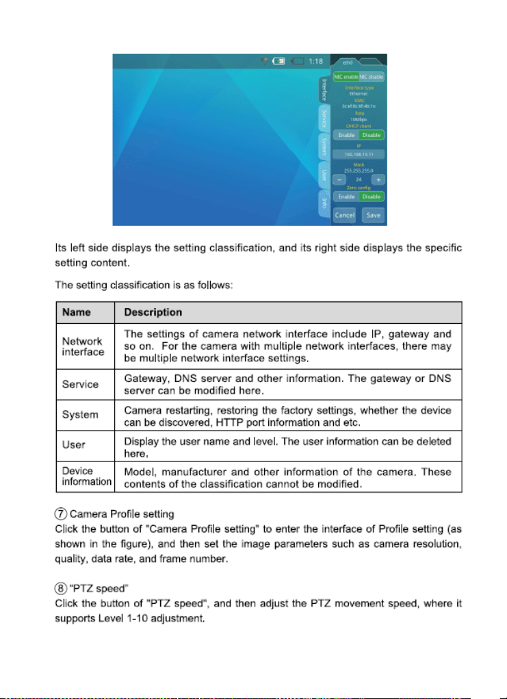
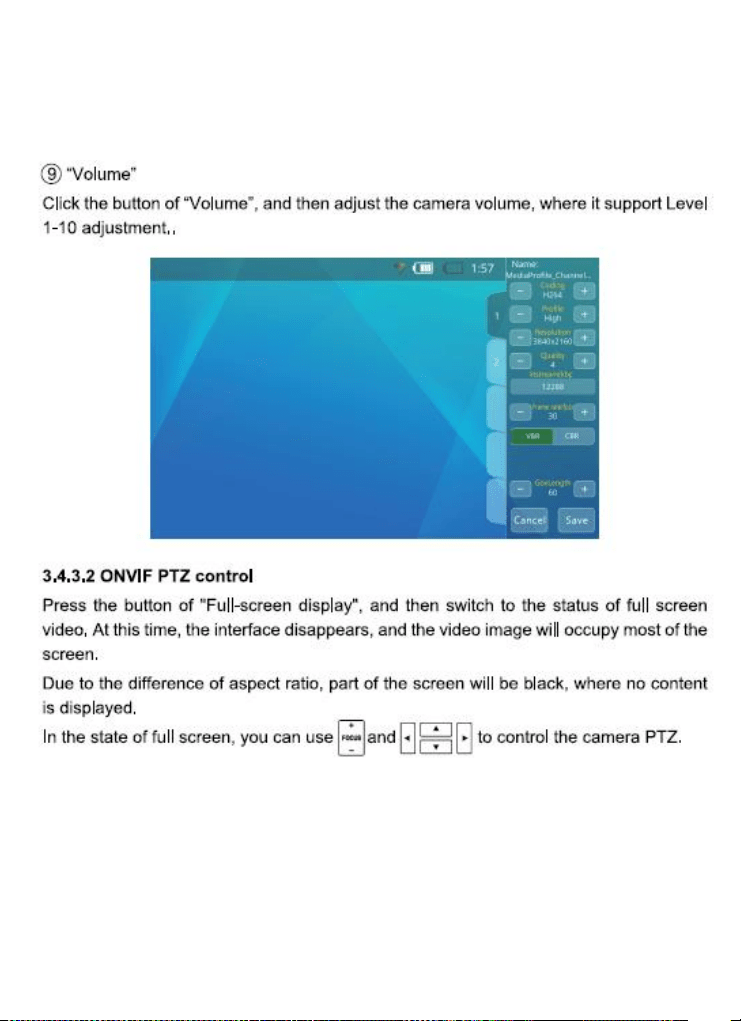
You can adjust the camera’s settings, and record still
images or video from the selected camera. You can
also check the audio signal from the camera if it is
equipped with a microphone. If the camera is directly
connected, the Tester will provide POE voltage to
power the camera.
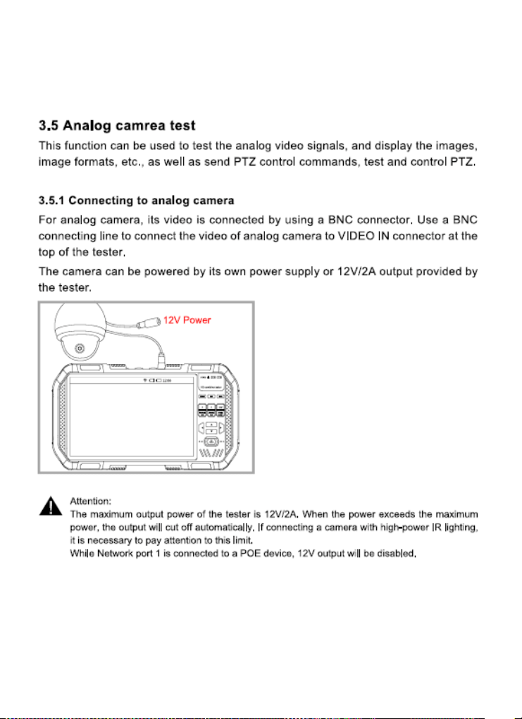
Standard Definition Analog Camera Test
The Tester can display the analog video signal input
from an attached analog camera or video source with
NTSC or PAL format video output. The Tester can
provide 12VDC (not to exceed 2A) to power the
camera. If the camera has an RS485 port for PTZ
control, the Tester can be used to test that

10 www.triplett.com UM-8075
functionality. The Tester provides support for more
than 30 PTZ command formats.
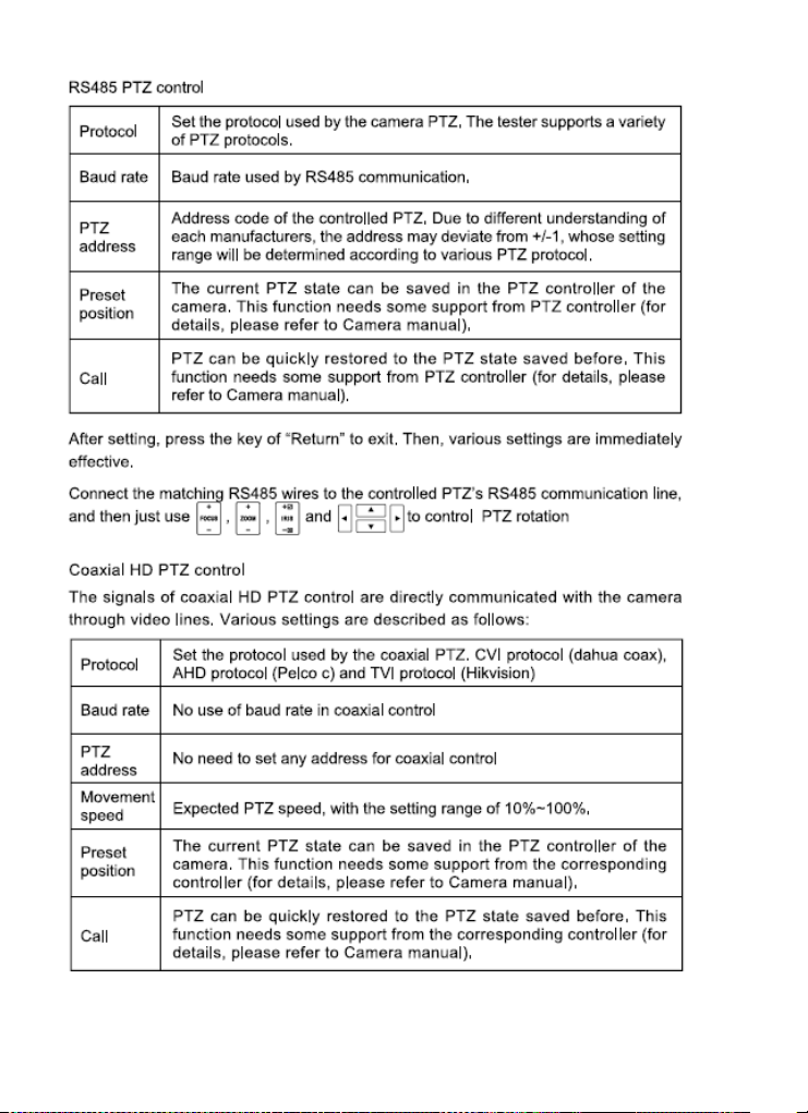
RS485 PTZ Control (Pan, Tilt, Zoom)
The Tester supports RS485 PTZ Control and more
than 30 kinds of PTZ Protocols which can be carried
out through the RS485 interface for control.
Data Monitoring
The Tester supports receiving data over RS485 and
displays on the screen for data analysis.
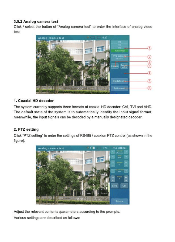
High Definition Analog Camera Test
The Tester will display the analog video signal input
from an attached analog camera or video source with
AHD 1.0 or TVI 2.0 format video output, HD-CVI 2.0
or AHD 2.0, CVI 3.0, or TVI 3.0. The Tester can
provide 12VDC (not to exceed 2.0 Amps) to power the
camera. If the camera has an RS485 port for PTZ
control, the Tester can be used to test that
functionality. The Tester provides support for more
than 30 PTZ command formats.
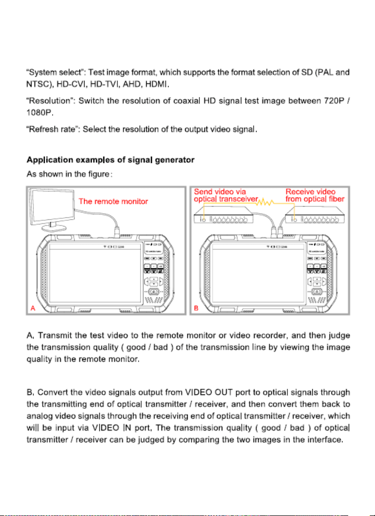
Video Test Image Generator
This function mainly generates video signals, which
can be used to test analog transmission lines, video
recorders etc., It has the capability to display the input
video simultaneously on the display for easy
comparisons to the image being generated. The video
formats supported include PAL and NTSC, HD-CVI,
HD-TVI, AHD and HDMI.
POE and DC Output
The Tester will automatically detect if a camera needs
to be supplied with POE when an IP camera is directly
connected to Network Port 1 (i.e., the blue port).
Network Port 2 accepts POE to test the POE output of
installed PSE network devices. You may also use the
Tester’s 12VDC output jack to power analog cameras.

11 www.triplett.com UM-8075
Audio Test
The Tester can be used to check audio signal
functionality which is input on the Tester’s audio input
jack.
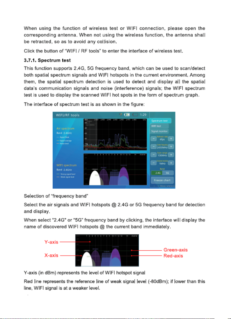
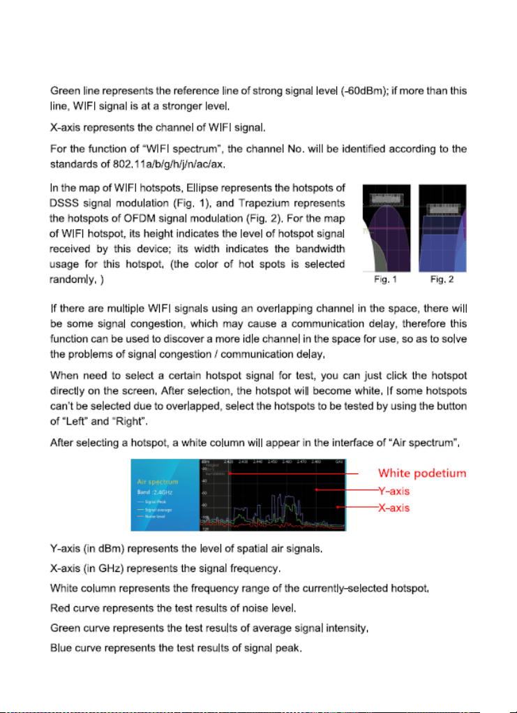
WIFI & RF Tools
The Tester supports RF Spectrum Testing, WIFI
Testing and Signal monitoring @2.4G, 5G
bandwidths. This can be effective in detection of WIFI
signal interference and determining if the data channel
is being blocked or has conflicts. Signal Strength
Detection can help engineers find the most suitable
location and direction for WIFI connections by quickly
detecting the signal strength.
Network Test
The Tester may be used to perform several Ethernet
network test functions, including:
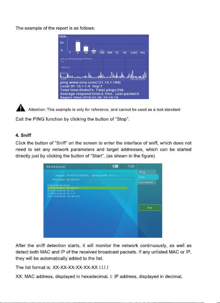
Network Sniff: Monitors and displays Ethernet MAC
IDs and IP addresses broadcast on the network
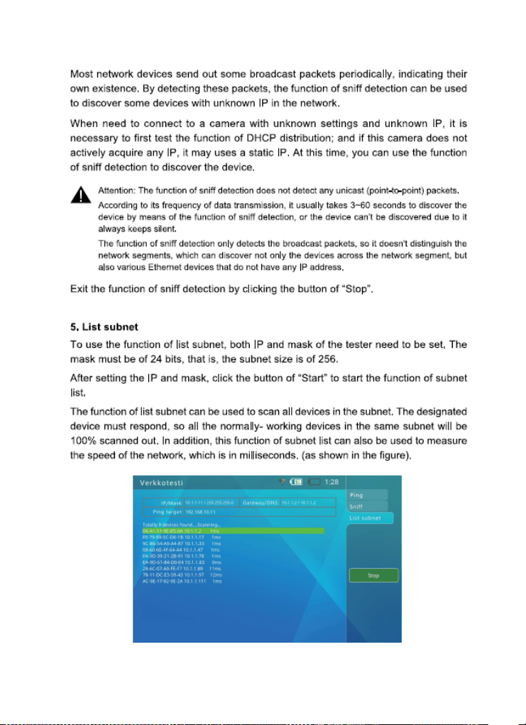
Subnet List: Monitors and displays Ethernet MAC IDs
and IP addresses broadcast on the selected
subnet according to IP and mask settings
Ping Test: Performs the standard ping messaging
response test on the specified destination IP
address
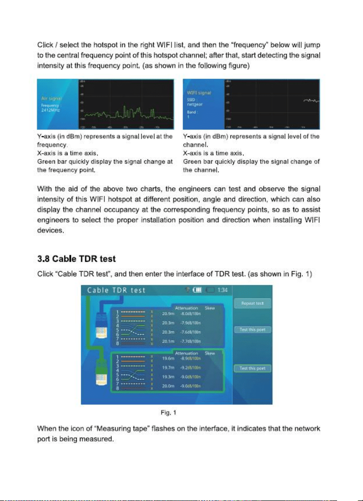
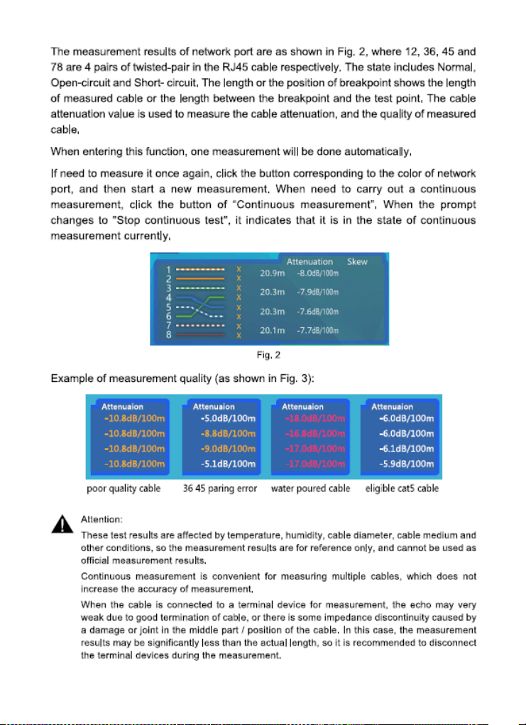
TDR & RJ45 Cable Test
The Tester may be used to check the condition of the
RJ45 cable pairs (normal, open, short) and perform a
cable length measurement test using TDR. TDR
(Time-Domain Reflection)
The Tester may be used to check the condition of the
RJ45 cable pairs (normal, open, short) and perform a

12 www.triplett.com UM-8075
cable length measurement test using TDR. TDR
(Time-Domain Reflection)
Video Snapshot, Recording and Playback
The Tester supports allows video snapshot and
recording under the conditions of video playback
during the ONVIF test and analog video test (SD and
HD) Allows for playback of any saved snapshot or
video.
Basic Operation
Installing the Battery
The CamView IP series of testers use a rechargeable
lithium-ion polymer battery. To ensure safety when
transporting, always disconnect the battery from the
tester. The device may leave the factory with one of
the following two battery placements:
The battery is placed inside tester and
insulated from the contacts with a thin, plastic sheet.
In this case, the user should open the battery cover,
take out the battery, remove the plastic sheet, then
put the battery back in, and put the battery cover
back on.
The battery is placed outside the tester. In
this case, the user should open the battery cover, put
the battery securely into the battery compartment,
and put the battery cover back on.
Note — The tester will automatically turn on when the
battery is properly placed in the device for the first
time.
Charging the Battery

13 www.triplett.com UM-8075
Be sure to fully charge the battery prior to first use. If
the battery level is too low, the charge indicator will
flash 3 times, and the device won’t turn on.
You should use the POE injector and ethernet cable
provided by the manufacturer to charge the battery.
To charge the unit, connect one end of the ethernet
cable to the Data/Power-out Port on the POE
Injector, then connect the other end of the ethernet
cable to the Network Port 2 (Green outline) on the
tester. Once you have connected the ethernet cable
on both ends, plug in the power cord for the POE
Injector into a power outlet. Network Port 2 will light
up with an orange light when the internal battery is
recharging.
Frequently Asked Questions About the
Battery
The Tester uses a lithium-ion polymer
battery, which does not have a memory effect. Users
can recharge the battery whenever they want.
When recharging, the Charge Indicator
on the tester will light up red. When the battery is
fully charged, the light will turn off.
Due to calculation deviation or other
reason, the battery level can be as low as 90% when
the charge light turns off. Users can ensure their
battery Is fully charged by extending the charge time
for up to 60 minutes.

14 www.triplett.com UM-8075
Lanyard
Users can choose to install the lanyard. The lanyard
can help when handling the device, prevent dropping
the device, avoid damage to the device, and prevent
loss.
To install the lanyard, put one end of the lanyard
through the hole at the top of the device, turn back and
go through the slip-lock (i.e., the plastic piece similar
to a buckle).Tighten the lanyard and confirm that it is
locked in position.
Powering the Device ON/OFF
To turn on the device, press and hold the Power
Button for more than 2 seconds. The Power
Indicator will light up green when the device is turned
on.
To turn off the device, press and hold the Power
Button for more than 2 seconds. When the device is
turned off, the green Power Indicator light will turn
off after the device is fully shut down. Users can also
setup the idle auto power off feature.
LED Worklights
The tester LEDs at the top of the unit also double up
as an LED Worklight. In the ON or OFF state simply
quick press the Power button two times to toggle the
worklight on or off. Great feature for working in low
light conditions.
15 www.triplett.com UM-8075
16 www.triplett.com UM-8075
17 www.triplett.com UM-8075
18 www.triplett.com UM-8075
19 www.triplett.com UM-8075
20 www.triplett.com UM-8075
21 www.triplett.com UM-8075
22 www.triplett.com UM-8075
23 www.triplett.com UM-8075
24 www.triplett.com UM-8075
25 www.triplett.com UM-8075
26 www.triplett.com UM-8075
27 www.triplett.com UM-8075
28 www.triplett.com UM-8075
29 www.triplett.com UM-8075
30 www.triplett.com UM-8075
31 www.triplett.com UM-8075
32 www.triplett.com UM-8075
33 www.triplett.com UM-8075
34 www.triplett.com UM-8075
35 www.triplett.com UM-8075
36 www.triplett.com UM-8075
37 www.triplett.com UM-8075
38 www.triplett.com UM-8075
39 www.triplett.com UM-8075
40 www.triplett.com UM-8075
41 www.triplett.com UM-8075
42 www.triplett.com UM-8075
43 www.triplett.com UM-8075
44 www.triplett.com UM-8075
45 www.triplett.com UM-8075
46 www.triplett.com UM-8075
47 www.triplett.com UM-8075
48 www.triplett.com UM-8075
49 www.triplett.com UM-8075
50 www.triplett.com UM-8075
51 www.triplett.com UM-8075
52 www.triplett.com UM-8075
53 www.triplett.com UM-8075

54 www.triplett.com UM-8075
ABOUT TRIPLETT
Triplett Test Equipment and Tools has been designing specialized test equipment for over 100 years.
Triplett was acquired by Jewell Instruments in 2007. Jewell Instruments is a world
leader in the manufacturing and distribution of advanced sensors, controls, panel
meters, and avionics. Jewell provides custom solutions for the aerospace, medical,
industrial, marine, telecommunications, and railroad industries.
Jewell’s experienced engineering team works with customers and end-users to
develop top-of-the-line products that meet or exceed all customer requirements.
The company has two manufacturing facilities—one in Manchester, New
Hampshire, and the other in Barbados, West Indies. Both facilities maintain the
most stringent manufacturing requirements. The Barbados facility also provides
the cost-competitive advantage of offshore manufacturing
Jewell is committed to continuing the legacy started by Ray L. Triplett, producing
only the high-est quality, most technologically advanced, rugged, and reliable test
equipment products in the marketplace.
Jewell Instruments Headquarters
Manchester, NH
USA
