50P FLEX
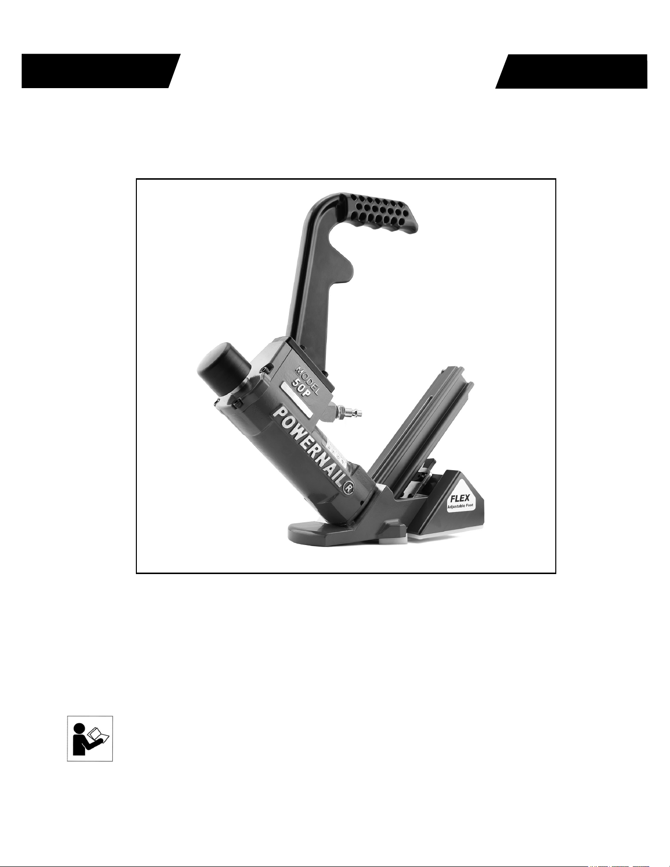
Powernail 50P FLEX Pneumatic Powernailer
®
POWERNAIL
®
CO.
OPERATION AND MAINTENANCE MANUAL
MANUAL DE OPERACION Y DE MANTENIMIENTO
MANUEL D’INSTRUCTIONS ET D’ENTRETIEN
Read this manual before you use this Powernailer®. Follow all safety warnings and
instructions. If you are uncertain about the operation of the nailer, call us directly
at 1-800-323-1653 for assistance or contact the closest Powernail Dealer for help.
Please retain this information for future reference.
WARNING
REV 2024.04.25
REV 3 MASTER

The Powernail 50P FLEX Pneumatic Nailer is designed
to bring Powernail quality to a pneumatic nailer. For
those looking for the ease of use of a pneumatic tool, the
Powernail 50P FLEX is designed for use with only 1" ,
1-1/4", 1-1/2" and 1-3/4" (18 gauge) Powercleats® nails.
The Powernail 50P FLEX is recommended for use on
thinner 3/8", 1/2", 5/8" and 3/4" solid tongue and groove
hardwood as well as some other hard exotics, bamboo,
and engineered woods. For a superior pneumatic Nailer,
look to the company that has been the industry’s quality
leader, POWERNAIL® COMPANY, INC.
INTRODUCTION
2
INDEX
LIMITED WARRANTY
POWERNAIL® Company, Inc. warrants to its customer, and to the fi rst end-use purchaser of
POWERNAIL fl ooring nailers purchased from an authorized POWERNAIL distributor, that
each serialized manufactured nailer by POWERNAIL®, for a period of 12 months from the
date of purchase, and with respect to the nailer body (specifi cally Models 200, 445, and 50P),
for a period of 10 years from date of purchase, (“warranty period”); shall be free of defects in
materials and workmanship and will meet POWERNAIL’s specifi cations in effect at the time
of Product shipment. POWERNAIL will repair or replace, at its option, any Powernailer®
that does not conform to this warranty. Claims must be made no later than fi fteen (15) days
after the end of the warranty period. POWERNAIL will perform all repair or replacements
itself or through its authorized contractors. POWERNAIL is not responsible for shipping,
labor or other direct or indirect costs. Damage caused by abuse, misuse, unusual or excessive
wear is excluded. Repair or modifi cation of the Products by unauthorized parties will void this
warranty. The customer is responsible for returning Products to POWERNAIL for verifi cation
of nonconformance. Warranties for Products not manufactured by POWERNAIL are limited to
warranties provided to POWERNAIL by the manufacturer of such product that are assignable
to customer.
THESE WARRANTIES AND REMEDIES ARE EXCLUSIVE OF ALL OTHERS, EXPRESS
OR IMPLIED. THE WARRANTIES OF MERCHANTABILITY AND FITNESS FOR
PURPOSE ARE EXPRESSLY EXCLUDED. IN NO EVENT SHALL POWERNAIL’S
LIABILITY FOR A WARRANTY CLAIM EXCEED THE PRICE PAID TO POWERNAIL
FOR THE NONCONFORMING PRODUCT, REGARDLESS OF THE FORM OR BASIS OF
THE CLAIM OR CAUSE OF ACTION.
Index..................................... 2
Warranty............................... 2
Safety Instructions................ 3
Powernail Company Info...... 3
Operating Instructions.......... 4-9
Top Load Channel................. 5
Parts & Service.................... 6-9
Drive Blade........................... 7
Seal Replacement................. 7-9
Parts List.............................. 10-12
Rear Load Channel and
Original Foot Parts List......... 12
Schematic ........................... 13
Seal Locations Diagram....... 14
Safety Labels........................ 15
Depth Chart.......................... 16
Clear a jam with the R2 foot.. 18
Troubleshooting Chart......... 19
3
SAFETY INSTRUCTIONS
POWERNAIL COMPANY, INC.
1020 Williams Road, Genoa City, WI 53128 US
Phone: 1-800-323-1653 OR 262-292-5300
www.powernail.com
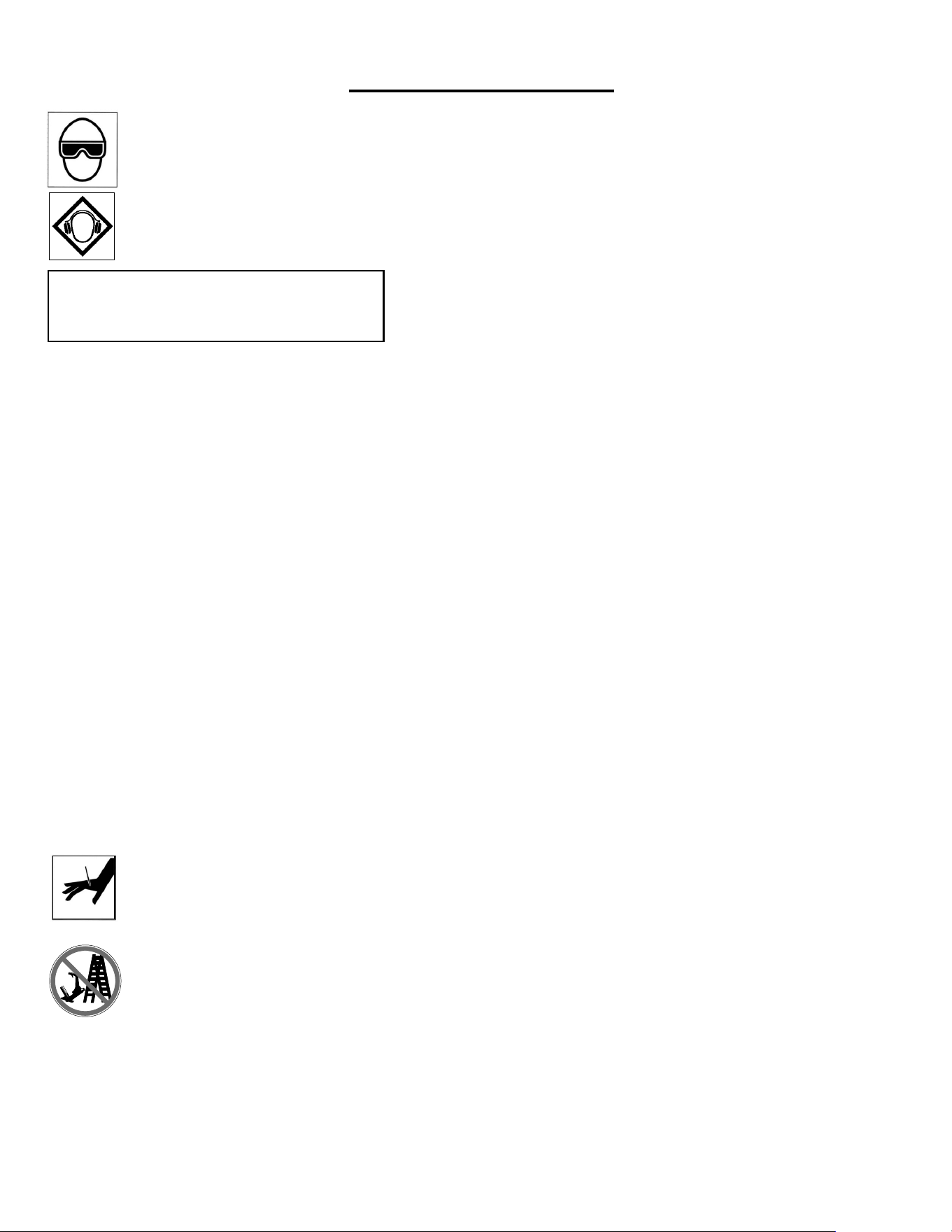
Always use approved SAFETY GLASSES and EAR PROTECTION when operating this Nailer. The
operator and others in the work area should always wear approved FRONT and SIDE eye protection
when operating this Nailer. Eye protection will help guard against fl ying nails and debris, which could
cause severe eye injury.
EYE AND EAR PROTECTION should be used to prevent hearing damage when there are high noise
levels in the work area.
ALWAYS use ear plugs with a noise reduction rated at 29 db or highter at a construction site.
Nailer noise ratings are at LPA-1sd=90.6,
LWA-1sd=99.3 and LPA-1s,1m=86.3.
Nailer vibration rating: m/s2=3.05.
Always DISCONNECT THE AIR SUPPLY before making any adjustments, repairing, clearing jams or when the
Nailer is not in use. Do not use on scaffolding or ladders and disconnect nailer from air supply when transporting
between installation areas.
Never attach the female end of a quick disconnect to the Nailer. This will trap air inside the Nailer and permit it to
be discharged. Only the unrestricted male connection should be attached to the Nailer.
Nailer requires an air source that can continuously deliver 80 to 110 psi at 3-1/2 cubic feet of air per minute for
operation.
Normal air pressure should not exceed 120 psi or damage to the Nailer and seals may occur. Excess air pressure
can cause the Nailer to explode.
To prevent fi re or explosion, use only regulated compressed air—do not use bottled gases of any kind (no oxygen
or combustible gasses) to power this Nailer.
Nailer is intended for use installing wood fl ooring and is not to be used for purposes not specifi ed in the operations
manual.
Do not use any nails other than Powernail Powercleats Nails which are specifi cally designed for use in any
Powernailer. Powercleats Nails are available in various lengths. Contact your Powernail Dealer for Powercleats
Nails.
Use only Powernail replacement parts in the repair or maintenance of this nailer. Parts or repair services are
available from the manufacturer or from agents authorised by the manufacturer. Repairs should be carried out
only by trained service personel in the fi eld of fastener driving tools who will observe proper safety controls while
performing maintenace. Service personel should be qualifi ed to to asses the safe working condition of fastener
driving tools.
Never place any part of the body in the discharge path of the Nailer when air is connected to the Nailer. Always
make sure Nailer is empty of cleats before connecting air hose so as to prevent any accidental discharge from
occurring.
Never leave the Nailer unattended while it is connected to an air supply.
Whenever air is connected to the Nailer, keep body parts away from the nail discharge path. Disconnect
the air line before making adjustments or repairs on the Nailer. Only connect air to an unloaded Nailer
so as to prevent accidental discharge.
Nailer is activated by striking the plunger. Do not work on scaffolding, ladders, elevated
or uneven surfaces where the nailer could fall and self-activate. Do not leave air
attached to the Nailer when moving from one install location to another.
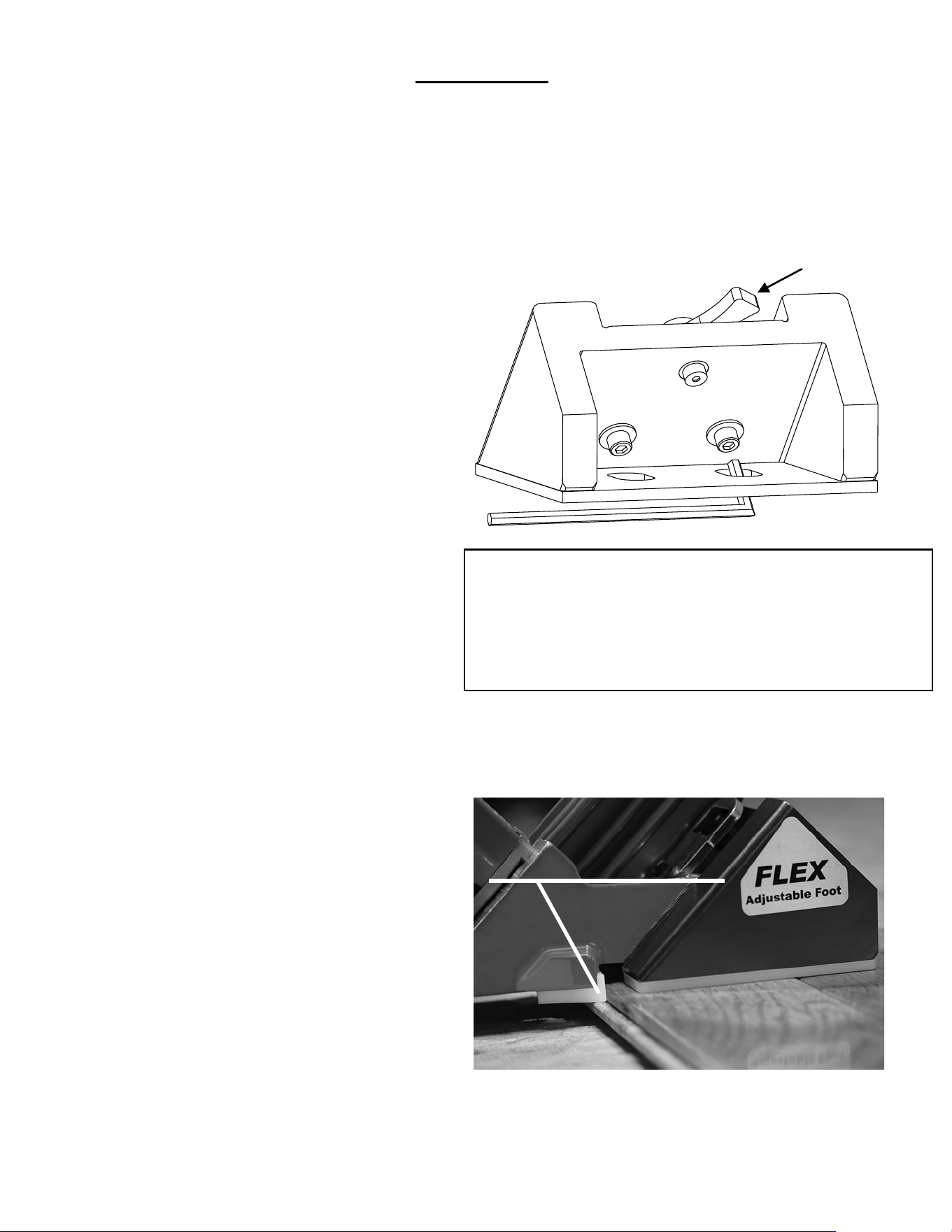
Figure 2.
Set the nailer on a sample of your fl ooring.
Raise the nailer foot above the tongue
to line up the nail pocket.
4
Read these instructions carefully before you use the Nailer.
1. Loosen 2 hex screws.
2. Raise or lower the FLEX to your wood sample.
3. Match the Locating Ear to the nail pocket.
4. Tighten 2 hex screws.
5. Test wood sample with new adjustment.
Hex Allen Wrench
FLEX
Adjustment Lever
Figure 1.
FLEX Tri-Glide Foot Adjustment:
Wood varies from one manufacturer to the next. The
different wood profi les may be due to height and
length of the fl ooring tongue and whether or not there
is a nail pocket.
To use the Powernail 50P Flex, adjust the nailer FLEX foot to a sample of your fl ooring (see instructions below).
When the nailer foot is adjusted to your fl ooring, simply place the nailer on the fl oor and pull nailer back so the
triangles (Figure 2) catch the edge of the fl oor above the tongue. Hit the plunger with the rubber-capped mallet-end
to let the Nailer drive and set the nail at the correct 45 degree angle.
First, loosen the two hex bolts under the FLEX foot with
the Allen Wrench supplied with the nailer. (Figure. 1.)
Next, set the nailer on a sample of your fl ooring
Use the adjustment lever at the back of the nailer foot to
raise or lower the nailer to the wood.
Match the Adapter Foot Triangles so that it is pointing
into the 90° angle created
by the tongue and the top of the wood (see Figure 2).
For wood with a nail pocket, line up the Triangles at the
top of the nail pocket.
When the adjustment lever is in the correct position
for your wood sample, tighten the two hex bolts to
lock the FLEX foot into place.
Always check your adjustment with a sample to
ensure the nail is driving into the nail pocket.
OPERATION
Adjust so the Triangles
sit slightly above fl ooring tongue
5
OPERATION, continued...
Figure 4.
Figure 5.
Figure 6.
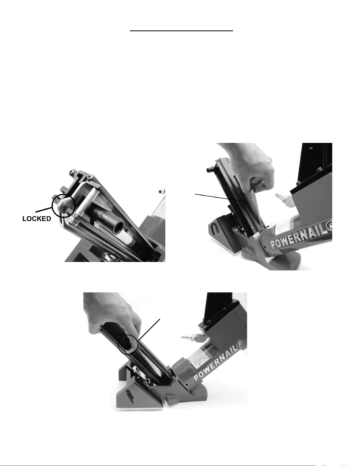
To Load the Powernail Flex:
Pull back the spring loaded nail pusher towards the end of the channel until the pusher plate locks (Figure 4).
Place up to one stick (100) of Powercleats® (18-gauge) nails, 1" , 1-1/4" , 1-1/2" or 1-3/4" long into the nail
feed slot located on the top of the channel (Figure 5). Release nail pusher from locked position and gently
guide it down until it meets the end of the cleat strip (Figure 6).
To Unload
Pull back the spring loaded nail pusher towards the end of the channel until the pusher plate locks. Then turn
the nailer over so that the nails slide out of the top nail feed slot.
Loading Top Load Channel:
INSERT
CLEATS INTO
TOP FEED
SLOT
GENTLY RELEASE
PUSHER FROM LOCKED
POSITION AND GUIDE
IT TO THE END OF THE
CLEAT STRIP

6
OPERATION, continued...
WARNING: It is not necessary to hit the Nailer
hard to activate it. Never hit the Nailer with
excessive force or with the metal end of the
mallet, this will damage the Nailer.
Before each use check all screws to be sure
they are tight. Shock and vibration can loosen
screws. Do not over tighten any screw.
AIR SUPPLY:
The air must be clean and dry. Dirty and/or wet
air will damage the Nailer. A combination fi lter-
regulator-lubricator is required for proper Nailer
performance and should be placed close to the
Nailer per manufacturer’s recommendations.
The air source must continuously deliver 80 to
110 psi at 3-1/2 cubic feet of air per minute to
operate the Nailer. Connect a clean air hose
and air regulator to the Nailer.
Check for air supply leaks that waste air and
starve the Nailer of air thereby reducing its
performance.
LUBRICATION:
If you do not use an in line lubricator, you must
lubricate the Nailer manually. The frequency
of lubrication is dependent upon the duty cycle
of the Nailer. Continuous duty requires more
frequent oiling than intermittent duty.
At least every eight (8) hours place two to four
drops of Pneumatic Light Air Tool Oil into the
disconnected air line male connector attached
to the Nailer.
WARNING: Detergent oil is not
recommended and may damage the seals.
WARNING: Do not over lubricate the Nailer,
excess oil mist or drops will be vented with
spent air when over lubricated. Excess oil could
stain the wood fl ooring, walls or furnishings. Dry
fi re the Nailer, without nails, to purge excess oil,
before you begin to nail down fl ooring. We will
not be responsible for oil stains. Before storing
the Nailer, lubricate and cycle the Nailer in insure
internal parts are oil protected from corrosion.
PARTS & SERVICE:
When ordering parts include the part number,
part description, Powernailer model and serial
number. Be sure to state the quantity of the
part(s) required. Contact your Powernail Dealer
for the necessary parts or service.
WARNING: Never work on the Nailer if the air line
is attached. Always disconnect the air line from
the Nailer fi rst.
NAILER DISASSEMBLY:
TO REPLACE RUBBER BUMPER (#24):
1. Disconnect the air supply
2. Remove the four (4) cap screws holding the
Adapter Foot, Foot and Nail Channel assembly to
the main Body.
3. Pull the Rubber Bumper out of the cylinder
bore. Replace the old Bumper if it shows signs of
wear or it is split.
4. Reverse these steps to reassemble the Nailer.
Be sure to align the Driving Blade with the slot in
the Nail Channel Assembly while you reassemble
the Nailer. NEVER FIRE THE NAILER WITHOUT
THE RUBBER BUMPER INSTALLED, IT WILL
DAMAGE THE NAILER.
For Step-by-Step Videos and Instructions,
Visit our Web Site at: www.Powernail.com
FLEX Foot
Adjustment Video
Service and
Maintenance Videos

TO REPLACE DRIVING BLADE(#15):
1. Disconnect the air supply
2. Remove the four socket head cap screws
holding the Adapter Foot, Foot and Nail Channel
Assembly to the body.
3. Remove the Rubber Bumper
4. Pull the Driving Blade with pliers until the Piston
is fully extended outward towards the bottom of the
cylinder.
5. Use a 15/16” box wrench (Part #: 09-44529768)
to unscrew the Driving Blade Jam Nut and remove
it. Hold the Piston from turning while unscrewing
the Jam Nut by holding the piston hex with a 1-1/8”
box wrench (Part #: 09-44529768).
6. Push out the 1/4" diameter blade retaining
Dowel Pin and remove the broken Driving Blade
stub.
7. Install a new Driving Blade in the slot and
replace the Dowel Pin. Screw on the retaining Jam
Nut using the same tools. If the Jam Nut becomes
worn and loose after frequent removals, it should
be replaced.
8. Check the fi t, there should be some sideways
movement between the Driving Blade and the
Jam Nut assembly. This is desirable and helps the
blade to align itself with the mating parts.
9. Reassemble the components. Be sure to align
the Driving Blade with the slot in the Adapter Foot
Assembly, it goes in only one way.
SEAL REPLACEMENT:
There are 7 seals that may require replacement.
We recommend that you have your POWERNAIL
Dealer replace the Seals.
SEAL KIT:
You may choose to buy a Seal Replacement Kit
and replace the seals yourself. It is good practice
to replace all seals at one time regardless if only
one seal needs replacement.
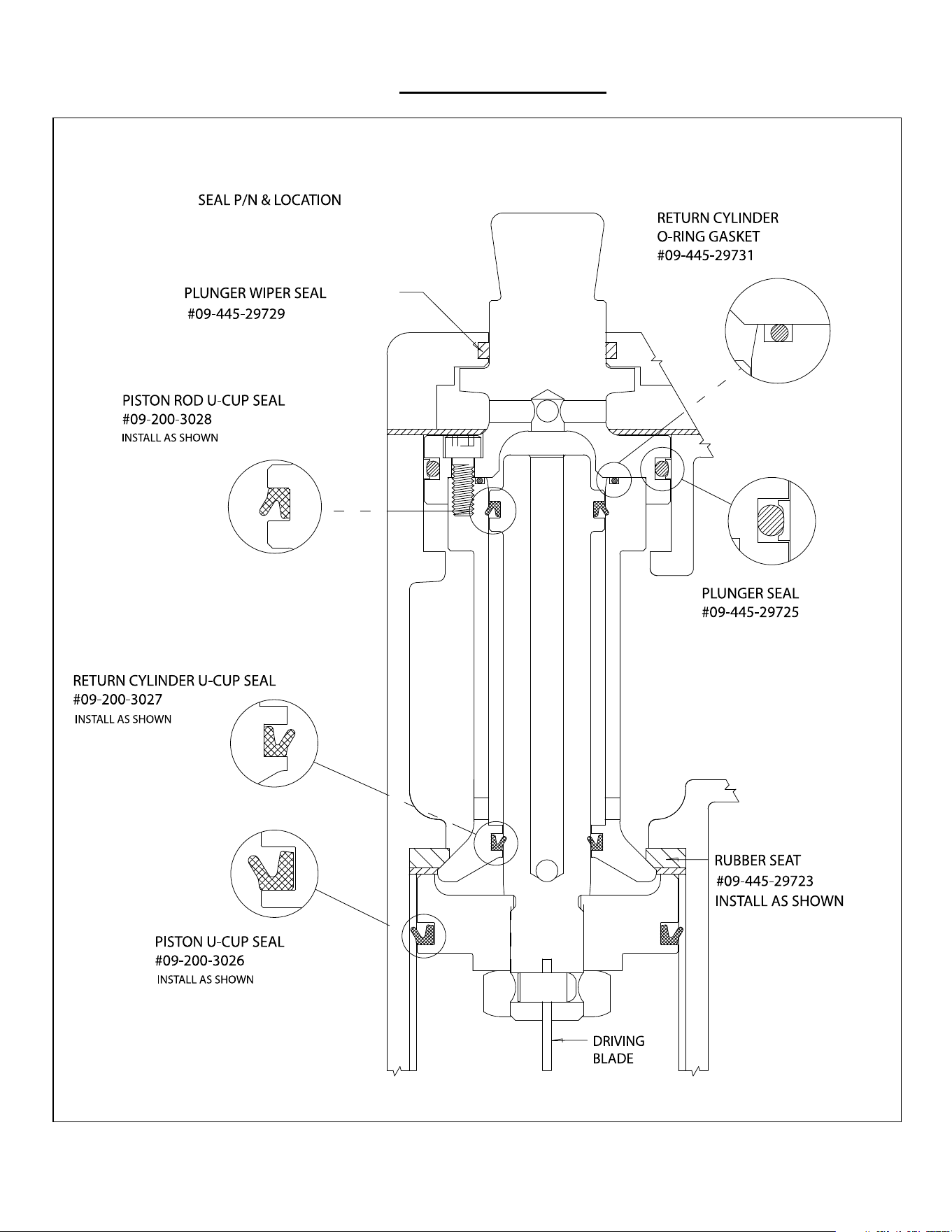
SEAL DESCRIPTION & NUMBER:
1. Piston U cup Lip Seal (#21)
2. Return Cylinder U cup Lip Seal (#17)
3. Piston Rod U cup Lip Seal (#12)
4. Rubber Seat (#18)
5. Plunger Seal Set (#10)
6. Plunger Wiper Seal (#4)
7. Return Cylinder 0 Ring Gasket (#11)
To change Seals follow these procedures.
Be sure the air line is disconnected from the
Nailer fi rst before making any repairs. Consult
the illustration for the name and location of the
following component parts.
SEAL REPLACEMENT REQUIRES
REMOVAL OF THE DRIVING BLADE ASSEMBLY:
1. Disconnect the air supply.
2. Remove Rubber Plunger Cap (#7).
3. Unscrew & remove Body Cap (#2).
Unscrew the three 10-32 cap screws holding the
Plunger (#9) to the Return Cylinder (#16).
5. Pull the Plunger up and out of the Nailer Body
(#1) cavity.
6. Remove the Return Cylinder 0 Ring Gasket
(#11) located on the top of the Return Cylinder
under the Plunger.
7. Turn the Nailer over and remove the four foot
screws (#45), that fasten the Adapter Foot and
Nail Channel Assembly to the Nailer Body and lift
the Assembly off the Body.
8. Remove the Rubber Bumper (#24).
9. Pull the Driving Blade Assembly out of the
Nailer Body by pulling on the Driving Blade.
10. Hold the Piston Rod (#13) with an 11/16"
socket over its hex end opposite the Piston.
Do not use pliers or a vise anywhere on the
metal parts, they can damage the sealing
surfaces.
11. Use box wrenches to remove the 5/8-18 Jam Nut
(#22). Remove the Dowel Pin (#14) and Driving
Blade (#15).
7
OPERATION, continued...

8
OPERATION, continued...
12. Unscrew the Piston from the Piston Rod using box
wrenches and separate the Piston, Piston Rod and
Return Cylinder.
TO REPLACE THE SEALS:
Plunger Seal Set (#10):
1. Remove the Tefl on
®
Seal and its O-ring
expander from the Plunger groove using a bent
paper clip or pick. Be sure not to scratch the inside
walls of the seal groove with the wire hook.
2. Clean out the seal groove. Place a new O-ring
into the seal groove by stretching it over the
Plunger body. Make sure the O-ring is not twisted
in the groove. Place a new Tefl on
®
Seal Ring into
the seal groove over the O-ring.
3. Carefully push the Tefl on® Seal Ring over the
edge of the Plunger with your thumbs and into the
groove. Do this as quickly as possible to reduce
stretching of the Tefl on
®
Seal Ring. DO NOT
OVER STRETCH THE TEFLON
®
SEAL RING. Be
sure the Tefl on
®
Seal Ring is centered all around
the seal groove and not twisted.
4. Wipe off the Seal surface with a clean rag and
lubricate it generously with Pneumatic Light air tool
oil lubricant.
Rubber Seat (#18):
1. Remove the Cylinder Sleeve (#23). The
Cylinder Sleeve would slide out of the Nailer Body
when you pull out the Driving Blade
2. Remove the metal Support Ring (#19) and
Rubber Seat from inside the Nailer body. NOTE
THAT THE CHAMFER ON THE INSIDE OF
THE RUBBER SEAT FACES THE BOTTOM OF
THE NAILER. Do not reverse the direction of the
chamfer when you replace the Rubber Seat.
3. Replace the Rubber Seat, Support Ring and
Cylinder Sleeve. Be sure to re install the steel
Cylinder Sleeve with the chamfered inside edge
facing the BOTTOM of the Nailer.
Piston U Cup Lip Seal (#21):
1. Remove the old Piston U Cup Lip Seal from the
Piston using a bent paper clip or pick, being
careful not to scratch the inside walls of the
seal groove or the edge of the Piston with the
wire hook.
2. Clean out the seal groove. Place a new
U-Cup Lip Seal into the groove. Make sure the
lip seal is not twisted in the groove and the lips
face the top of the Nailer. See the sketch on
page 12.
3. Carefully wipe off the U Cup Lip Seal surface
with a clean rag and lubricate it generously with
Pneumatic Light air tool oil lubricant.
Return Cylinder U Cup Lip Seal (#17):
1. Use a bent paper clip or pick to remove
the old U Cup Lip Seal from the internal seal
groove inside the Return Cylinder. Be careful
not to scratch the inside walls of the seal
groove with the wire hook.
2. Clean out the seal groove. Place a new
U Cup Lip Seal into the groove, be sure it is
not twisted in the groove. Be sure the lips are
facing the inside of the Return Cylinder as
shown on the Seal Placement sketch on page
12.
3. Carefully wipe off the Lip Seal surface with
a clean rag and lubricate it generously with
Pneumatic Light air tool oil lubricant.
WARNING: The U-Cup Lip Seals #17 and #12
look alike, but they are different, DO NOT mix
them up.
Piston Rod U-Cup Lip Seal (#12):
1. Remove the old U-Cup Lip Seal from the
seal groove with a bent paper clip or pick using
care not to scratch the inside walls of the seal
groove with the wire hook.
2. Clean out the seal groove and install a new
U-Cup Lip Seal. Be sure the Lips are facing the
right direction and are not twisted in the groove.
See the sketch on page 12.

3. Carefully wipe off the Lip Seal surface with
a clean rag and lubricate it generously with
Pneumatic Light air tool oil lubricant.
Plunger Wiper Metal Cap O-Ring (#4):
1. Use a bent paper clip to pick out the Wiper
Seal out of its groove in the Body Cap (#2).
2. Clean out the groove and insert the new
O-Ring (#4) in to the groove in the metal body
cap (#2).
Return Cylinder O-Ring Gasket (#11):
1. Place a new O-Ring Gasket in the groove
on top of the Return Cylinder when you
reassemble the Driving Blade Assembly.
2. Wipe off the O-Ring Gasket seal surface and
lubricate it generously with Pneumatic Light air
tool oil lubricant.
REASSEMBLING THE NAILER:
1. Be sure the Rubber Seat, Support Ring and
Cylinder are installed in the Body and are facing
the correct direction.
2. All seal surfaces must be clean and
lubricated generously with Pneumatic Light air
tool oil lubricant.
Replace any part that shows signs of wear.
3. Use care when installing the seals into their
respective cavities. Be sure the Seals are
contained in their groove and do not come out
as the parts slide together. Generous cavity
lead in chamfers have been provided to help
Seal installation.
4. Carefully insert the Piston Rod into the
Return Cylinder and screw the Piston onto the
rod. Be sure the Piston is facing the correct
way, ears up, hex down.
5. Assemble the Driving Blade, Dowel Pin and
Jam Nut on to the Piston Rod.
6. Insert the Driving Blade Assembly up into the
bottom of the Nailer Body Cylinder.
7. Be sure there is a new O-Ring Gasket in the
top groove of the Return Cylinder.
8. Insert the Plunger into the top cavity of the
Body. Line up the holes and install the three
Plunger retaining screws. It is important that the
three #10-32 screws are tight or air leakage will
occur. Our recommendation is to use 1-2 drops
of blue Loctite® or similar on the 3 screws.
9. Install the Body Cap and Plunger Rubber Cap.
10. Turn the Nailer upside down. Install the
Rubber Bumper, Nail Channel Assembly and
Adapter Foot. Be sure to align up the Driving
Blade with the slot in the Foot before the Nailer is
closed up.
11. NEVER FIRE THE NAILER WITHOUT
THE RUBBER BUMPER INSTALLED, IT WILL
DAMAGE THE NAILER BEYOND REPAIR.
For Step-by-Step Videos and Instructions,
Visit our Web Site at: www.Powernail.com
9
OPERATION, continued...

For this parts list and other Powernailer schematics, please visit the
Powernail Parts Store at www.powernail.com
POWERNAIL 50P FLEX PARTS LIST
10
KEY: S=Sold Separately, A= Sold as part of assembly, SEAL=Seal Kit, TU=Tune-up Kit, F=Factory Only
ITEM # PART NO. DESCRIPTION QTY TU
SOLD SEPERATE OR
ASSEMBLY / KIT #
1 09-50P3001 BODY 1 F
2 09-50P3150 CAP (LOW PROFILE) 1 S
3 09-50P3202 1/4-20 X 5/8" S.H.C.S. W/ PATCH (COVER) 4 S
4 09-44529729 PLUNGER WIPER METAL CAP O-RING 1 TU S, A-1
5 09-44529759 3/8 NPT 45 DEGREE STREET ELBOW 1 S
6 09-4455418 1/4" AIR FITTING 3/8" NPT 1 S
7 09-44529722 RUBBER CAP 1 TU S
8 09-44529832 #10-32 X 3/4” S.H.C.S. W/PATCH (PLUNGER) 3 S
9 09-50P3014 PLUNGER (LOW PROFILE) 1 S
10 09-44529725 PLUNGER SEAL SET 1 TU S, A-1
11 09-44529731 RETURN CYLINDER O-RING GASKET 1 TU S, A-1, A-6
12 09-2003028 PISTON ROD U-CUP LIP SEAL 1 TU S, A-1, A-6
13 09-50P3010 PISTON ROD 1 S, A-6
14 09-44529740 1/4 X 1/2 DOWEL PIN (DRIVING BLADE) 1 TU S, A-6
15 09-50P3018 DRIVING BLADE 1 TU S, A-6
16 09-2003013 RETURN CYLINDER 1 S, A-6
17 09-2003027 RETURN CYLINDER U-CUP LIP SEAL 1 TU S, A-1, A-6
18 09-44529723 RUBBER SEAT 1 TU S, A-1
19 09-44529721 SUPPORT RING 1 S
20 09-2003011 PISTON 1 S, A-6
21 09-2003026 PISTON U-CUP LIP SEAL 1 TU S, A-1, A-6
22 09-44529748 5/8-18 JAM NUT (DRIVING BLADE) 1 TU S, A-6
23 09-2003015 CYLINDER SLEEVE 1 S
24 09-44529724 RUBBER BUMPER 1 TU S
25XL 09-50P3201 HANDLE, X-LONG 1 S
25L 09-50P3200 HANDLE, LONG 1 S
26 09-44529744 1/4-20 x 3/4" SHCS W/PATCH 4 S
27L 09-50P3058 NAIL CHANNEL (TOP LOAD), LONG 1 S, A-20
27S 09-50P3056 NAIL CHANNEL (TOP LOAD), SHORT 1 S, A-16
28 09-50P3042R2 GATE (Revision 2) 1 TU S, A-14, A-16, A-20
29 09-50P3017R2 GATE PLATE (Revision 2) 1 TU S, A-14, A-16, A-20
30 09-50P3006R2 STEEL FOOT (Revision 2) 1 S, A-14, A-16, A-20
31 09-44529750 #8-32 X 1-1/2" FHCS (SPACER) 2 S, A-16, A-20
32 09-44529756 1/4 X 1" SPACER (CHANNEL) 2 S, A-16, A-20
33 09-44529751 #8-32 LOCKNUT (SPACER) 2 S, A-16, A-20
34 09-50P3046 1/4-20 x 5/8" SHCS w/patch Torx Drive T27 (R2) 2 S, A-14, A-16, A-20
35 09-50P3047 1/4-28 x 1/2" SHCS w/patch (R2 Gate Plate) 2 TU S, A-14, A-16, A-20
36 09-50P3045 #10-32 x 3/4" FHCS w/patch (R2 Gate) 3 TU S, A-14, A-16, A-20
37 09-50P3050 NAIL PUSHER (TOP LOAD) 1 S, A-9, A-15, A-16, A-20
38 09-50P3054 PUSHER PLATE (TOP LOAD) 1 S, A-15, A-16, A-20
39 09-50P3057 #10-32 x 1-1/2" SHCS (TOP LOAD) 1 S, A-15, A-16, A-20
40 09-44529735.2 NAIL PUSHER KNOB 1 S, A-9, A-15, A-16, A-20
41 09-50P3055 NAIL PUSHER SPRING (TOP LOAD) 1 S, A-9, A-15, A-16, A-20
42 09-445297341 SPOOL (TOP LOAD) 2 S, A-9, A-15, A-16, A-20

ITEM PART NO. DESCRIPTION QTY
A-1 09-2003058A SEAL KIT (1 EACH OF ALL SEALS) 1
A-6 09-50PDBA DRIVING BLADE ASSEMBLY 1
A-7 09-AW445 ALLEN WRENCH SET (3/16 & 5/32) 1
A-8 09-44529757A 6 OZ. INDUSTRIAL LIGHT AIR TOOL OIL 1
A-12 09-44529768 BOX WRENCH (2) 2
TU 09-50PTUKITR2C TUNE-UP KIT FOR ALL (R2) 50P, 50P FLEX, & 50P POWER ROLLERS 1
A-14 09-50PFOOTKIT R2 FOOT ASSEMBLY (includes R2 Foot, Gate, Gate Plate, and Screws) 1
A-15 09-50P3050A NAIL PUSHER ASSEMBLY (TOP LOAD) 1
A-16 09-50P3056A NAIL CHANNEL ASSEMBLY (TOP LOAD) 1
A-17 09-50P3100A FLEX TRI-GLIDE ADAPTER FOOT ASM W/ TRIANGLE (PLASTIC) SET & SCREW 1
A-18 06-99600 FLEX TRI-GLIDE CONVERSION KIT 1
A-19 09-50P3101A FLEX TRI-GLIDE PLASTIC TRIANGLES - SET OF 2 (ADAPTER FOOT) 1
A-20 09-50P3061A LONG CHANNEL ASSEMBLY (TOP LOAD) 1
09-50P3107 TRIANGLE (ALUMINIUM) 1
Powernail FLEX Assemblies, Kits and Accessories
11
KEY: S=Sold Separately, A= Sold as part of assembly, SEAL=Seal Kit, TU=Tune-up Kit, F=Factory Only
Item
#
PART NO. DESCRIPTION
Qty
Req’d
Tuneup
Kit
Separate, or As-
sembly
43 09-50P3053 #8-32 x 3/8"L FHCS w/patch (TOP LOAD) 1 S, A-15, A-16, A-20
44 09-50P3052 BUSHING (TOP LOAD) 1 S, A-15, A-16, A-20
45 09-44529747 1/4-20 X 1-1/4" SHCS W/PATCH (FOOT) 4 S
46 09-44529758 1/4 SPLIT RING LOCK WASHER (FOOT) 4 S
60 09-50P3100 FLEX ADAPTER FOOT (TRI-GLIDE) 1 S, A-17, A-18
61 09-50P3101A PLASTIC TRIANGLE - SET OF 2 (ADAPTER FOOT) 1 S, A-17, A-18, A-19
62 09-50P3102 1/4"-20 x 3/4"L FHCS 2 S, A-17, A-18
63 09-50P3077 BHCS #10-32 x .50" w/patch 2 S, A-18
64 09-50P3074 FLEX FOOT PAD 1 S, A-18
65 09-2003057 #10-32 X 1/2 FHCS (PAD) 4
S
66 09-50P3071 FLEX FOOT BRACKET 1 S
67 09-50P3073 FLEX FOOT CAM PLATE 1 S
68 09-50P3072 FLEX FOOT CAM 1 S
69 09-50P3079 BELLEVILLE DISC SPRING 1 S
70
09-50P3078 1/4 SH DIA X 1/2" SH. BOLT W/PATCH 1 S
71
09-50P3070 FLEX FOOT 1 S, A-18
72 09-50P3076 WASHER .281 ID X .62 OD X .051" T 2 S
73 09-50P3075 1/4-28 X 1-1/4" SHCS 2 S
09-44529801 HEX WRENCH 3/16 (FLEX FOOT) 1 S, A-7
09-44529802 HEX WRENCH 5/32 1 S, A-7
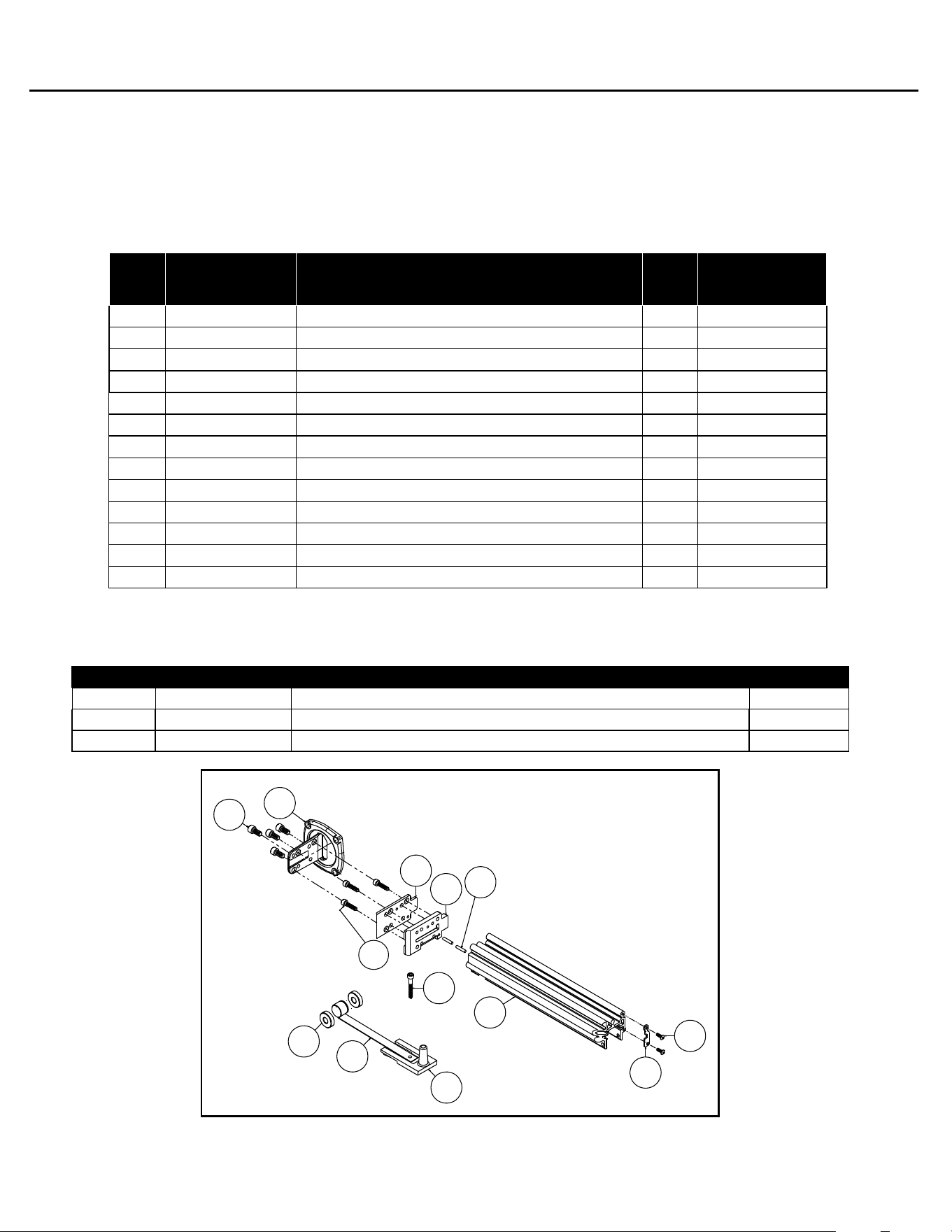
POWERNAIL 50P FLEX PARTS LIST
100
101
102
103
104
105
106
107
108
109
110
112
111
POWERNAIL 50P FLEX REAR LOAD CHANNEL AND ORIGINAL FOOT PARTS LIST
Original Foot / Gate
Rear Load Channel
ITEM PART NO. DESCRIPTION
QTY
A-30 09-50P3065A NAIL CHANNEL ASSEMBLY (Rear Load) 1
A-31 09-2003063A NAIL PUSHER ASSEMBLY (Rear Load)
1
09-50PTUKIT Tune-up Kit for all (original) 50P, 50P FLEX, & 50P Power Rollers 1
Powernail 50P FLEX Rear Load Channel Assemblies, Kits
12
If your nailer was manufactured in or before 2017, you may have the rear load channel
confi guration and/or original foot, gate, and gate plate. These parts have since been revised but
are still available as replacement parts. Please check your nailer to determine it's confi guration
before ordering parts.
Item
#
PART NO. DESCRIPTION
Qty
Req’d
Sold Separate or
Assembly #
100 09-50P3006 FOOT (Original) 1 S, A-30
101 09-44529754 #10-32 X 1/2" SHCS (FOOT) (Original) 4 S, A-30
102 09-44529822 #10-32 X 3/4" SHCS w/patch (GATE) (Original) 3 S, A-30
103 09-50P3017 GATE PLATE (Original) 1 S, A-30
104 09-50P3042 GATE (Original) 1 S, A-30
105 09-44529741 ROLL PIN (Original) 1 S, A-30
106 09-50P3008 CHANNEL (Rear Load) 1 S, A-30
107 09-50P3040 CHANNEL PLATE (Rear Load) 1 S, A-30
108 09-50P3041 #6-32 X 3/8" BHCS (Channel Plate) (Original) 1 S, A-30
109 09-44529745 #10-32 X 1-1/4" SHCS (Knob) (Rear Load) 1 S, A-30. A-31
110 09-2003035 SPOOL 2 S, A-30. A-31
111 09-2003034 NAIL PUSHER SPRING (Rear Load) 1 S, A-30. A-31
112 09-44529735 NAIL PUSHER (Rear Load) 1 S, A-30. A-31
13
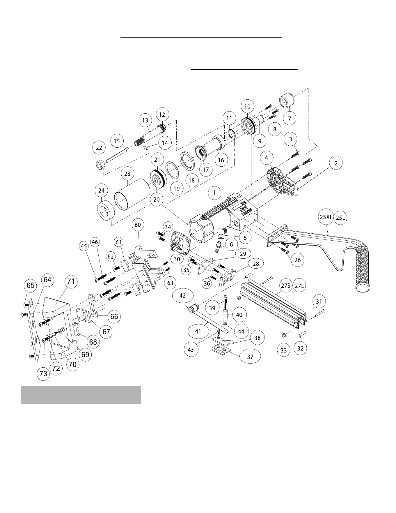
For this and other Powernailer schematics, please visit the
Powernail Parts Store at http://www.powernail.com
For Step-by-Step Videos and Instructions,
Visit our Web Site at: www.Powernail.com
POWERNAIL 50P FLEX SCHEMATIC
FLEX Conversion Parts.
#60-73
7
#11
#4
#12
#10
#17
#21
#18
14
SEAL PLACEMENT
15
CAUTION:
Lubricate
Nailer with
2-4 drops of
Industrial Light
Oil for every
8 hours of use.
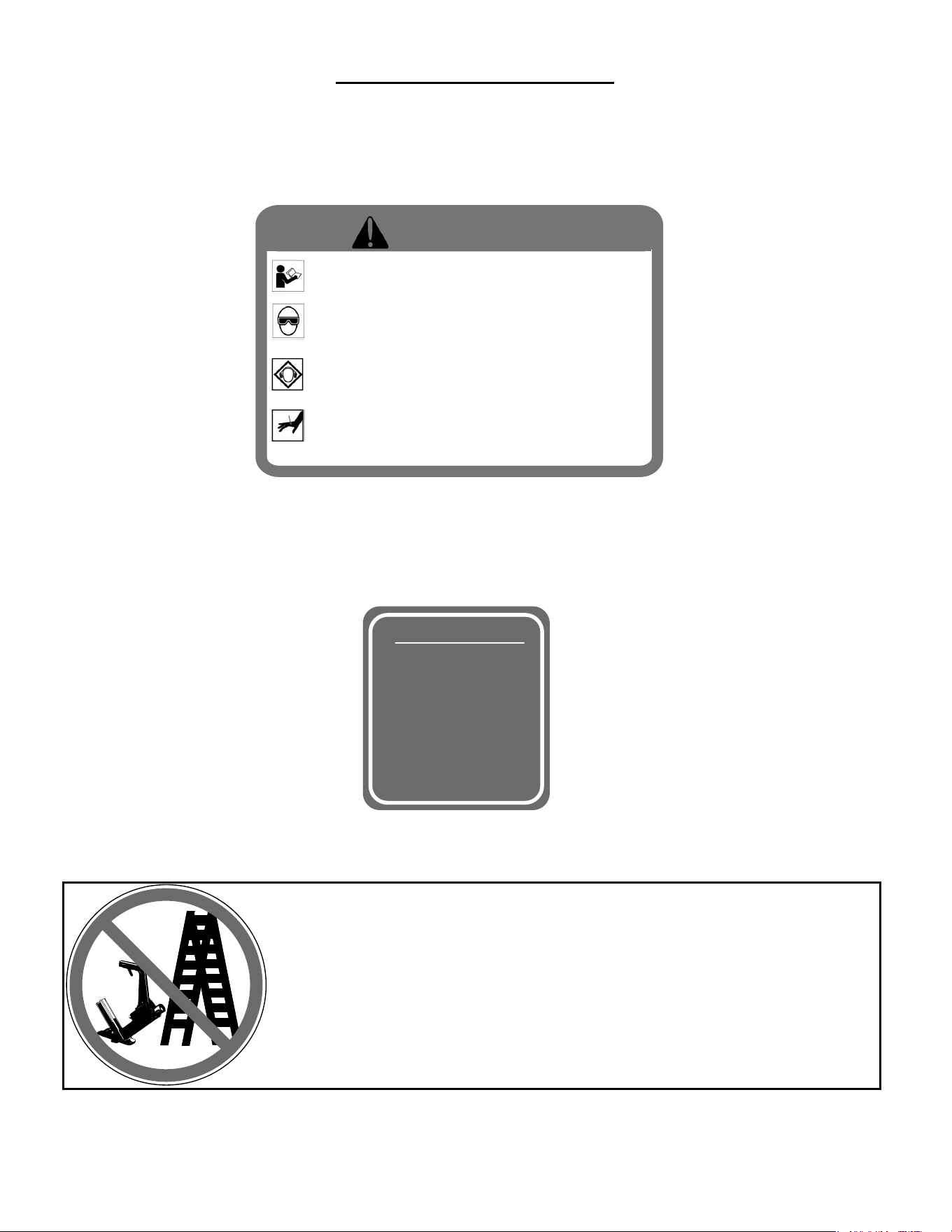
Nailer is activated by striking the plunger. Do not work on
scaffolding, ladders, elevated or uneven surfaces where the
nailer could fall and self-activate. Do not leave air attached to
the Nailer when moving from one install location to another.
NAILER SAFETY DECALS
• Read and understand the tool labels and
manuals before operating. • Operators and
others in work area MUST wear EYE and EAR
protection. • Use safety glasses with side
shields. • NEVER point tool at yourself or
others in the work area. • Only connect air to
an unloaded tool and always keep tool
pointed in a safe direction. • Disconnect air
when clearing jams, servicing or when tool is
not in use. • Use only clean, dry, regulated air
not exceed 110 psi. • Never use oxygen or
other bottled gasses-explosion may occur.
Warning!
©Powernail Company 2012
16
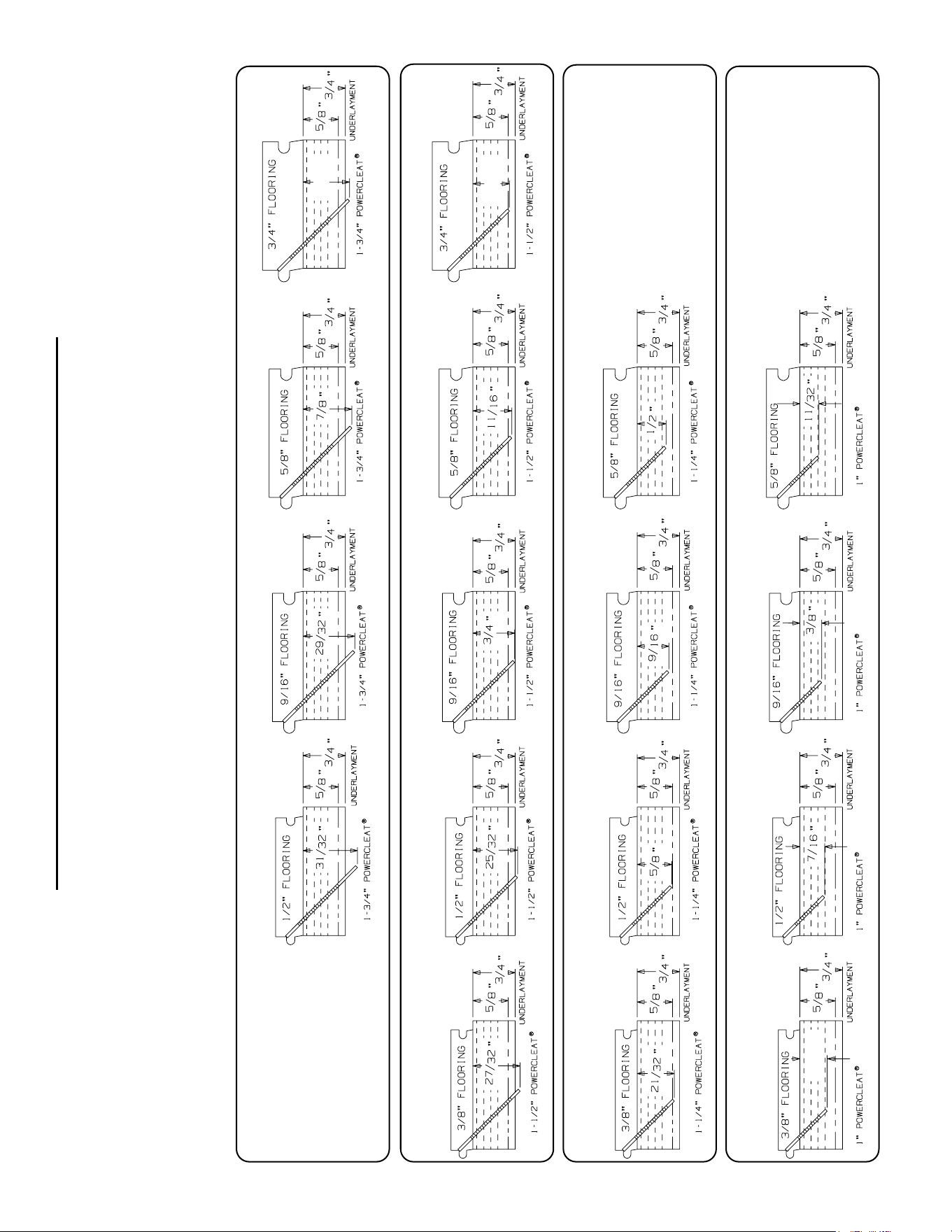
This chart will assist you in determining the proper length of Powercleats to use for various
thicknesses of fl ooring. Approximate vertical penetration of the Powercleat under the hardwood
fl oor is shown for each application. This is only a guide. Results should be tested in the fi eld before
proceeding.
POWERCLEATS LENGTH DETERMINATION CHART
Nail Penetration for 3/4" and 5/8" Underlayment
1-1/ 2” 18 GAUGE POWERCLEATS®
1-3/ 4” 18 GAUGE POWERCLEATS®
1-1/ 4” 18 GAUGE POWERCLEATS®
1” 18 GAGE POWERCLEATS®
18 GAUGE
18 GAUGE
18 GAUGE
18 GAUGE
18 GAUGE
18 GAUGE
18 GAUGE
18 GAUGE18 GAUGE
18 GAUGE
18 GAUGE
18 GAUGE
18 GAUGE
18 GAUGE
18 GAUGE
18 GAUGE
18 GAUGE
13/ 16”
15/ 32”
5/ 8”
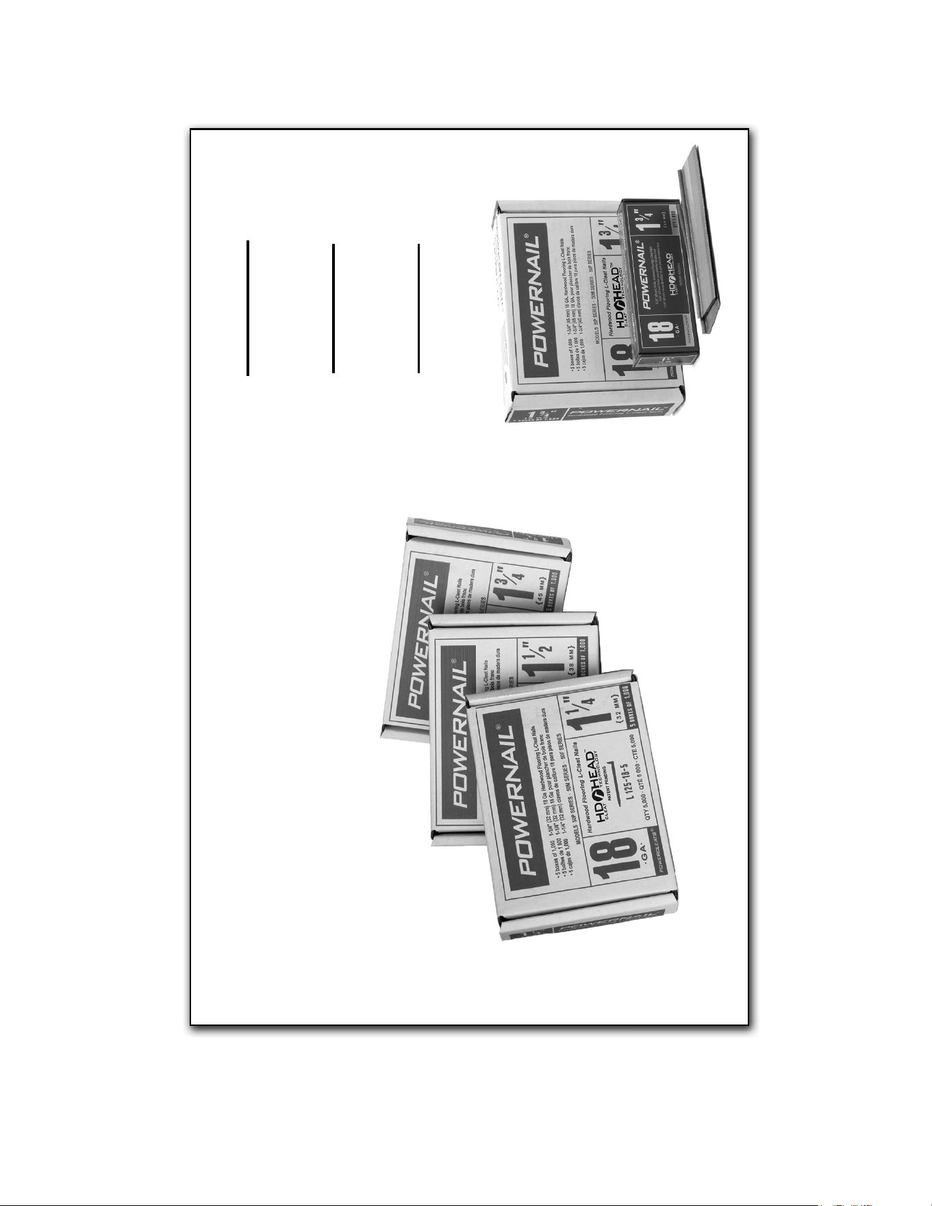
17
1¼” 5 Pack
(5 x 1,000 Cleats)
Part #: L125185
1½” 5 Pack
(5 x 1,000 Cleats)
Part #: L150185
1¾” 5 Pack
(5 x 1,000 Cleats)
Part #: L175185
18 GA HD POWERCLEATS
®
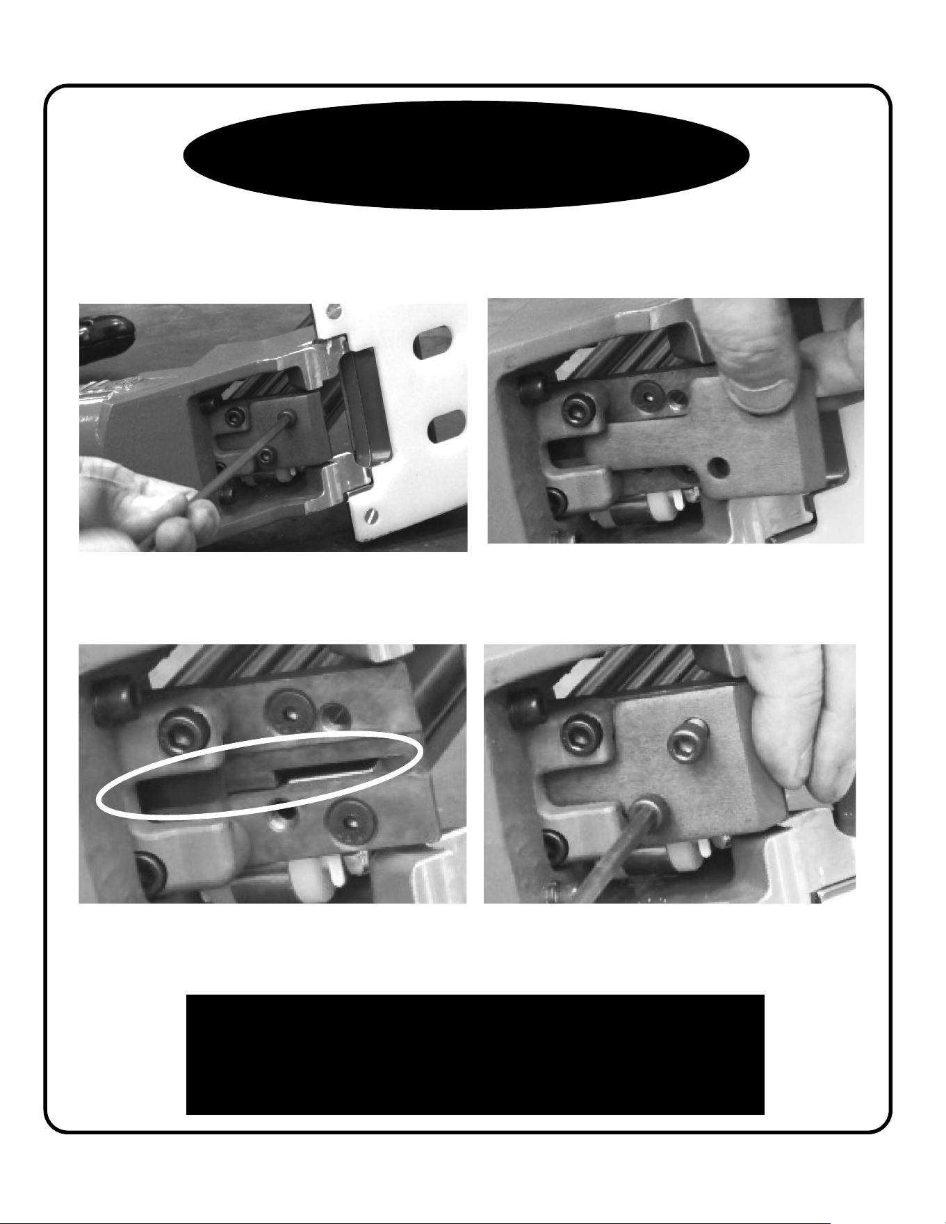
1. Using a 3/16” hex wrench, remove
the two gate plate screws.
Clearing a jam with the new
Revision 2 Foot.
Nailer is now ready for use.
2. Slide and remove the gate plate.
3. Inspect and clear any jams in the
drive blade pathway.
4. Re-install the gate plate and screws.
Tighten fi rmly.
Check out our Repair and Maintenance
Videos online at:
https://www.powernail.com/service-videos/
18

PROBLEM POSSIBLE CAUSE SOLUTION
1
Driving blade
does not
retract
1. Zero or Low air pressure
Check air supply for 80 psi minimum to 110 psi
maximum
2. Lack of lubrication Manually lubricate through male air inlet fi tting
3. Excessive dirt inside nailer Disassemble and clean
4. Bent or burred driving blade Replace driving blade (#17)
5. Seals worn out Replace all seals (Seal Kit)
6. U-Cup Lip Seals installed upside
down
Replace all seals (Seal Kit)
2
Driving blade
retracts slowly
1. Low air pressure Turn up air pressure to 80-110 psi max
2. Bent or burred driving blade Replace driving blade (#17)
3. Air supply restricted by small orifi ce Use 1/4" minimum diameter air fi ttings
4. U-Cup Lip Seals installed upside
down
Replace all seals (Seal Kit)
5. Excessive dirt inside nailer Disassemble, clean and lubricate
3
Nail is not
countersunk
1. Low air pressure Turn up air pressure to 80-110 psi max
2. Broken Driving Blade Replace Driving Blade (#17)
3. Nail hit hard surface Move from obstruction
4. Piston U-Cup Lip Seal installed
upside down
Replace all seals (Seal Kit)
5. Driving blade jam nut came loose Retighten or replace jam nut (#49)
6. Worn out gate Replace gate. (#15)
4 Nailer leaks air
1. Air supply fi ttings loose Tighten all air line fi tting connections
2. Excess air pressure blew out seals
Check air supply for 110 psi maximum—replace all
seals
3. Plunger screws loose Tighten 3 plunger screws (#24)
4. Cracked or damaged body Replace body (#1)
5. Seals worn out Replace all seals (Seal Kit)
6. Seals need to be seated Dry fi re Nailer
5
Bottom of nail-
er cracked off
1. Operated without rubber bumper
installed
Replace damaged parts
2. Excessive air pressure used Replace damaged parts
6
Nails jam in
nailer
1. Not using 18 gauge Powercleats nails Use 18 gauge Powercleats nails only
2. Continued use after a short hit Clear nail immediately after short hit
3. Nail pusher damaged or spring
broken
Replace nail pusher assembly (#A-9)
4. Nail channel lose Tighten nail channel retaining screws (#34,#45)
5. Bent nail stuck in nail guide Disassemble and clear out bent nail
6. Hit another set nail or hard object Move from obstruction
7. Nail gate worn out Replace nail gate (#28)
7
Plunger locked
up—won't
move or fi re
2. Lack of lubrication
Manually lubricate through male air inlet fi tting
19
POWERNAILER TROUBLE SHOOTING CHART
• Dealer Locator
• Rental Locator
• Parts Store
• Product Information
• Repair Tech Videos
• Cool Tools Cleat Calculator
• Cleat Depth Chart
• Training Schools
Visit www.Powernail.com
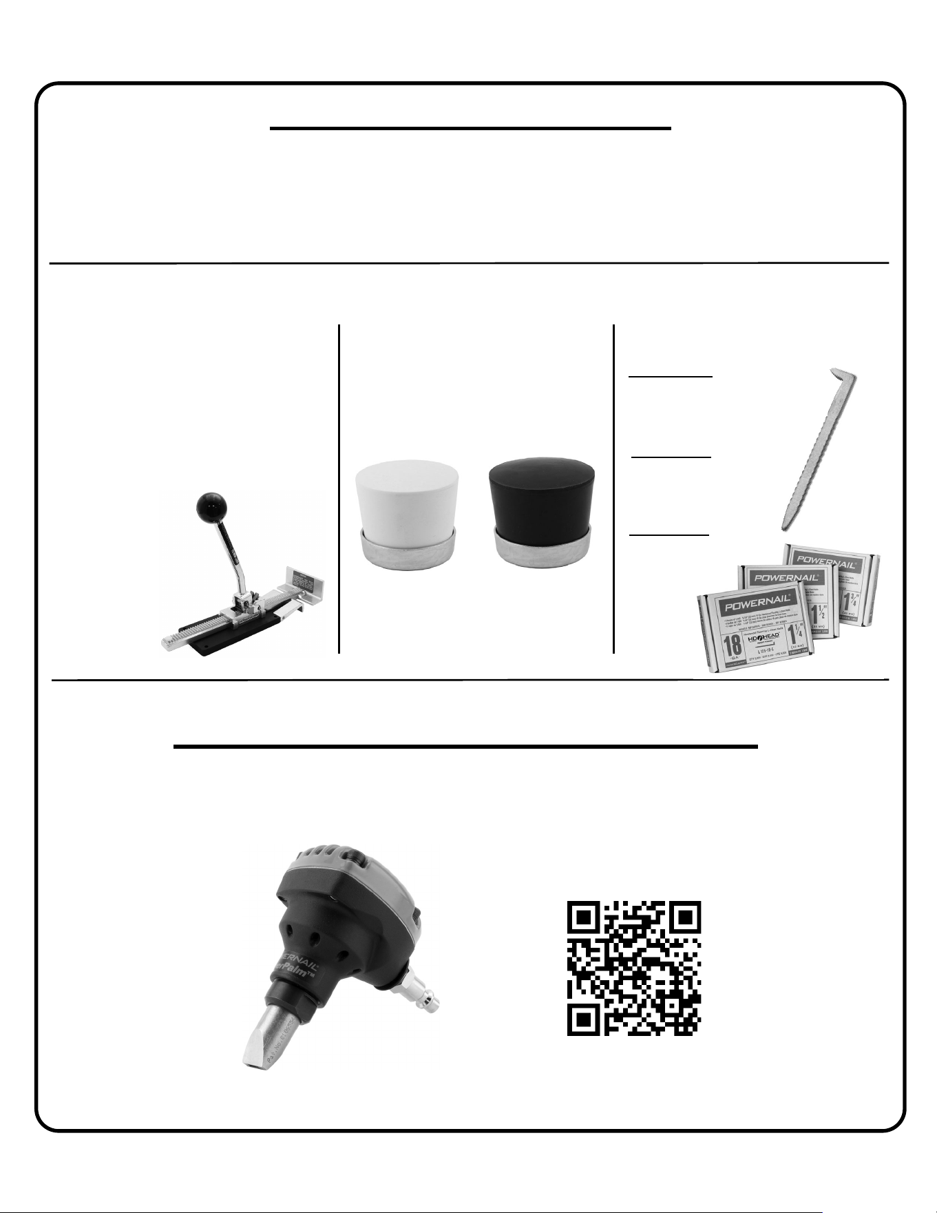
Featured Products
POWERNAIL® Warranty Registration
Register your warranty on the web and you will automatically be
entered to win a FREE!!! PowerPalm™.
Register at https://www.powernail.com/warranty-registration/
Scan this code with your phone to be
taken to our warranty registration form
18 Gauge Powercleats™
• Made in the USA and has a
1-year warranty
• Eliminates gaps and straightens
boards during installation
• Requires minimal effort to apply
maximum force
• Self-adjusting lip fi ts 5/16″ to 3/4″
fl ooring
• Safe for use on
fi nished fl oors
Powerjack® Model 500
P/N: PJ500
Includes a non-marring rubber cap
and steel ring. Fits on all our mallet
models.
Mallet Cap Replacement
Assemblies
P/N: 06-CAPAW
P/N: 06-CAPAB
1¼” 5 Pack
(5 x 1,000 Cleats)
P/N: L125185
1½” 5 Pack
(5 x 1,000 Cleats)
P/N: L150185
1¾” 5 Pack
(5 x 1,000 Cleats)
P/N: L175185