Read this manual before you use this Nailer. Follow all safety warnings and instructions. If you
are uncertain about the operation of the Nailer, call us directly at 1-800-323-1653 for assistance or
contact the closest Powernail Dealer for help. Please retain this information for future reference.
REV 2024.04.25
Operation and Maintenance Manual
MODEL 45 TONGUE AND GROOVE NAILER
POWERNAIL
®
CO.

2
LIMITED WARRANTY
POWERNAIL® Company, Inc. warrants to its customer, and to the fi rst end-use purchaser
of POWERNAIL MODEL 45 from an authorized POWERNAIL distributor, that each
serialized manufactured MODEL 45 by POWERNAIL®, for a period of 12 months from
the date of purchase. MODEL 45 shall be free of defects in materials and workmanship
and will meet POWERNAIL’s specifi cations in eff ect at the time of product shipment.
POWERNAIL will repair or replace, at its option, any Powernailer® that does not conform
to this warranty. Claims must be made no later than fi fteen (15) days after the end of the
warranty period. POWERNAIL will perform all repair or replacements itself or through its
authorized contractors. POWERNAIL is not responsible for shipping, labor or other direct
or indirect costs. Damage caused by abuse, misuse, unusual or excessive wear is excluded.
Repair or modifi cation of the Products by unauthorized parties will void this warranty.
The customer is responsible for returning Products to POWERNAIL for verifi cation of
nonconformance. Warranties for Products not manufactured by POWERNAIL are limited
to warranties provided to POWERNAIL by the manufacturer of such product that are
assignable to customer.
THESE WARRANTIES AND REMEDIES ARE EXCLUSIVE OF ALL OTHERS,
EXPRESS OR IMPLIED. THE WARRANTIES OF MERCHANTABILITY AND
FITNESS FOR PURPOSE ARE EXPRESSLY EXCLUDED. IN NO EVENT SHALL
POWERNAIL’S LIABILITY FOR A WARRANTY CLAIM EXCEED THE PRICE PAID
TO POWERNAIL FOR THE NONCONFORMING PRODUCT, REGARDLESS OF THE
FORM OR BASIS OF THE CLAIM OR CAUSE OF ACTION.
Please see the back of this manual for warranty registration instructions.
INDEX
Index..................................... 2
Warranty............................... 2 & 8
Powernail Company Info...... 2
Safety Instructions................ 3
Operating the tool................. 3
Schematic............................. 4
Parts List............................... 5
Drive Blade Replacement..... 6
Fastener Depth Chart............ 6
Notes and Records................ 7
Web Site................................ 8
Featured Products................. 8
POWERNAIL COMPANY, INC.
1020 Williams Road, Genoa City, WI 53128 US
Phone: 1-800-323-1653 or 262-292-5300
www.powernail.com

Always wear approved front and side EYE PROTECTION when operating this Nailer.
Others in the work area should also wear front and side EYE PROTECTION. Eye
protection will help guard against fl ying nails and debris, which could cause severe eye
injury.
EAR PROTECTION may be required to prevent hearing damage when there are high
noise levels in the work area.
DO NOT USE THE METAL END OF THE MALLET TO STRIKE THE PLUNGER, use
the rubber capped end only.
Never place any part of the body in the discharge path of the Nailer.
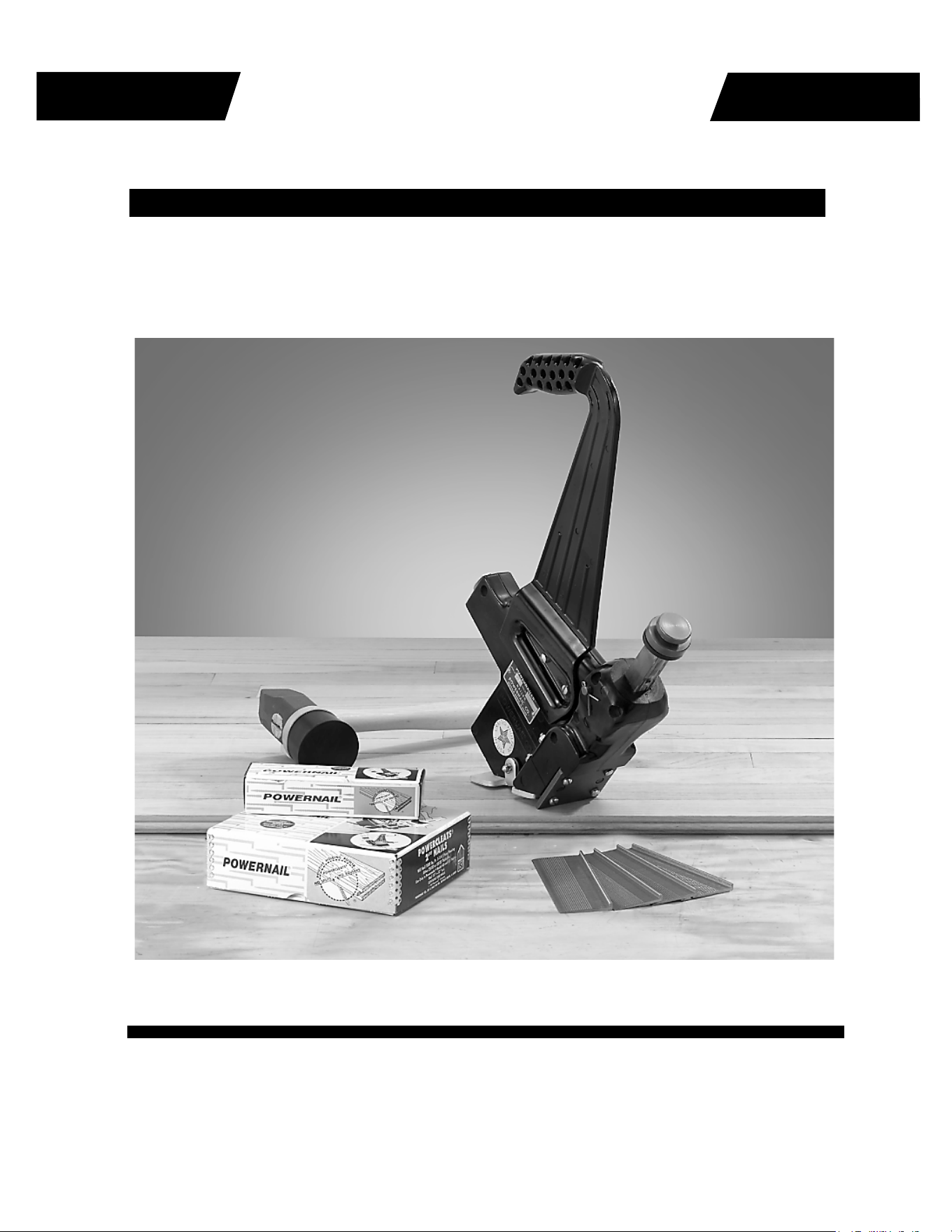
DESCRIPTION
OPERATION
TO PREVENT ACCIDENTAL INJURIES:
The Model 45 is a manual operated hardwood fl ooring nailer recommended for the
installation of 3/4″ to 5/8″ and 33/32″ tongue and groove fl ooring.
For a superior manual Nailer, look to the company that has been the industry’s quality
leader for over 50 years, POWERNAIL® COMPANY, INC.
WARNING
Do not use any nails other than Powernail Powercleats® (16 gauge) nails,
which are specifi cally designed for use in the Model 45 Powernailer. Powercleats® (16 gauge)
nails are available in 1-1/2", 1-3/4" or 2" lengths to accommodate 3/4″ to 5/8″ and 33/32″ tongue
and groove hardwood fl ooring.
3
1 Make sure fl ooring strips are together
tightly
2 Place nailer on tongued edge of fl ooring
3 Strike the plunger with rubber end of the
mallet
4 The nailer will drive and set the nail at the
correct 45 degree angle
TOOL OPERATION
1 Unclip the spring clip from the feeder
channel and remove the feeder channel.
2 Slide a clip of nails into the end of the nail
channel feed slot.
2 Insert the feeder channel into the channel
feed slot and clip on the spring clip.
3 Tension is now applied to the nails for use.
LOADING CLEATS
1 Unclip the spring clip from the feeder
channel and remove the feeder channel.
2 Tilt nailer back until nails slide out of nail
channel.
UNLOADING THE NAILER
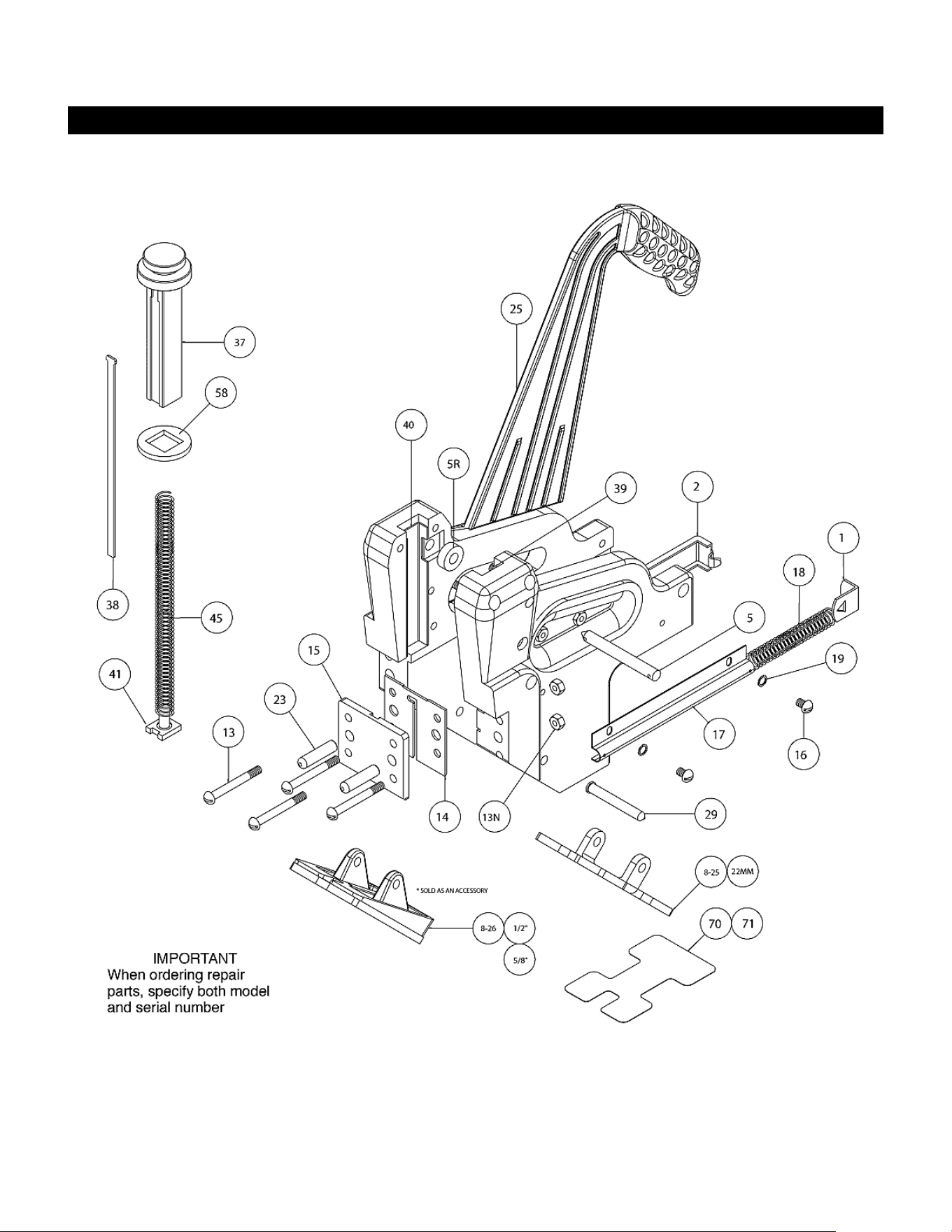
MODEL 45 EXPLODED VIEW
4

MODEL 45 PARTS LIST
ITEM # PART NO. DESCRIPTION QTY
REQ’D
KEY Assembly
or Kit
1 08-45-00-010 SPRING CLIP 1 S/K TU / OVH
2 08-45-00-020 FEEDER CHANNEL 1 S/K OVH
5 08-45-00-050 ROLLER PIN ASSEMBLY 1 S/K OVH
5R 08-45-00-05R ROLLER 1 S/K OVH
13 08-45-00-130 FOOT SCREW 4 S/K OVH
13N 08-45-00-13N LOCKNUT 4 S/K OVH
14 08-45-00-140 GATE 1 S
15 08-45-00-150 FOOT 1 S
16 & 19 08-45-00-160 SCREW & WASHER SET FOR SPRING CONT. (2 EA) 1 S/K OVH
17 08-45-00-170 SPRING CONTAINER 1 S/K OVH
18 08-45-00-180 FEEDER SPRING 1 S/K TU / OVH
23 08-45-00-230 DOWEL PIN 2 S
25 08-45-00-250 HANDLE ASSEMBLY 1 S
29 08-45-00-290 ADAPTER PLATE PIN ASSEMBLY 1 S
37 07-45-00-370 PLUNGER 1 S/K OVH
38 08-45-00-380 DRIVING BLADE 1 S/K TU / OVH
39 08-45-00-400 LEFT PLUNGER LINER 1 S
40 08-45-00-390 RIGHT PLUNGER LINER 1 S
41 08-45-00-410 PLUNGER SPRING PIN 1 S/K OVH
45 08-45-00-450 PLUNGER SPRING 1 S/K TU / OVH
58 08-45-00-580 BLADE RETAINER 1 S/K TU / OVH
70 06-99-720 #825 NO-MAR PAD (STICK-ON) .015 THICK 1 S
# 8-25 06-99-010 #825 ADAPTER PLATE ASSEMBLY FOR 3/4” T&G 1 S
ITEM # PART NO. DESCRIPTION QTY.
REQ’D
# 8-26 06-99-040 #826 ADAPTER PLATE ASSEMBLY FOR 1/2” T&G 1
# 8-26 06-99-04A #826 ADAPTER PLATE ASSEMBLY FOR 5/8” T&G 1
# 8-25 06-99-04B #825 ADAPTER PLATE ASSEMBLY FOR 22MM T&G 1
72 08-45-TU-KIT MODEL 45 TUNE-UP KIT 1
74 06-99-430 NAILER SHOE WITH ADAPTER ASSEMBLY 1
MODEL 45 ACCESSORIES
KEY: S=Sold Separately, TU=Sold as part of a Tune Up Kit, OV=Sold in an Overhaul Kit
5
6
REPLACING #38 DRIVING BLADE
1. Remove #5 Roller Pin--save Cotter Pin.
2. Holding Nailer in left hand with Nailer tilted
so rear of Nailer is down, depress #37 Plunger
Head slightly so #5R Roller is released from
Plunger Head.
3. Remove #37 Plunger Head from Body of Nail-
er by lifting straight out of Body.
4. Remove #38 Driving Blade from under #58
Rubber Blade Retainer. Discard Blade.
5. Insert new #38 Driving Blade with face of
Blade stamped “Front” facing front of Nailer,
under #58 Rubber Blade Retainer until the “T”
section at top of Blade fi ts into milled slot under
Plunger Head. Push #58 Rubber Blade Retainer
fl ush to underside of Plunger Head.
6. Holding Nailer in left hand with Nailer so rear
of Nailer is down, slowly insert Plunger Head and
Driving Blade Assembly into Nailer Body, making
certain the #45 Plunger Spring is inserted into
hole in Plunger Head.
7. While in this position, reinsert the #5 Roller Pin
and Cotter Pin.
8. Installation is complete and Nailer is ready to
use.
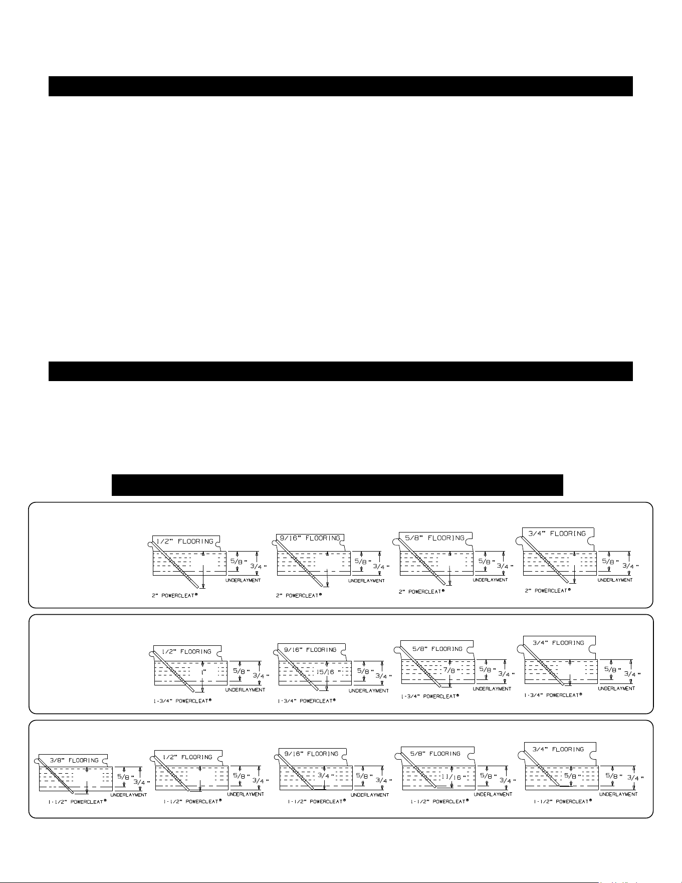
POWERCLEATS LENGTH DETERMINATION CHART
This chart will assist you in determining the proper length of Powercleats to use for
various thicknesses of fl ooring. Approximate vertical penetration of the Powercleat under
the hardwood fl oor is shown for each application. This is only a guide. Results should be
tested in the fi eld before proceeding.
Nail Penetration for 3/4" and 5/8" Underlayment
1-3/ 4” 16 GAUGE POWERCLEATS®
2” 16 GAUGE POWERCLEATS®
1-1/ 2” 16 GAUGE POWERCLEATS®
16 GAUGE 16 GAUGE
16 GAUGE
16 GAUGE
16 GAUGE
16 GAUGE
16 GAUGE16 GAUGE
16 GAUGE16 GAUGE16 GAUGE16 GAUGE16 GAUGE
1-3/ 16”
1-3/ 16”
1-1/ 8”
1-1/ 16”
1”
13/16”
7/8”

7
NOTES AND RECORDS
• Dealer Locator
• Rental Locator
• Parts Store
• Product Information
• Repair Tech Videos
• Cool Tools Cleat Calculator
• Cleat Depth Chart
• Training Schools
Visit www.Powernail.com
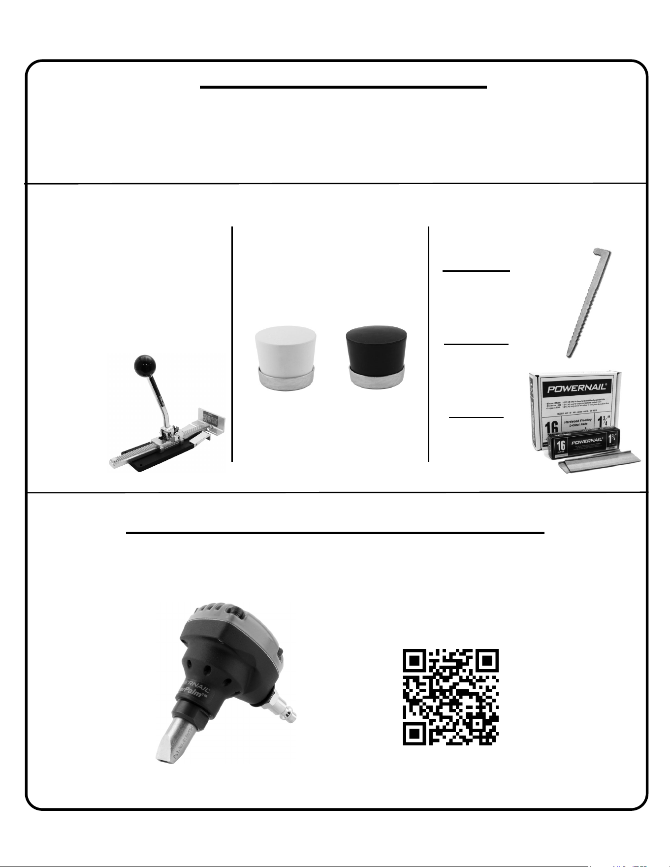
Featured Products
POWERNAIL® Warranty Registration
Register your warranty on the web and you will automatically be
entered to win a FREE!!! PowerPalm™.
Register at https://www.powernail.com/warranty-registration/
Scan this code with your phone to be
taken to our warranty registration form
16 Gauge Powercleats™
1½” 5 Pack
(5 x 1,000 Cleats)
P/N: L150165
• Made in the USA and has a
1-year warranty
• Eliminates gaps and straightens
boards during installation
• Requires minimal eff ort to apply
maximum force
• Self-adjusting lip fi ts 5/16″ to 3/4″
fl ooring
• Safe for use on
fi nished fl oors
Powerjack® Model 500
P/N: PJ500
1¾” 5 Pack
(5 x 1,000 Cleats)
P/N: L175165
2” 5 Pack
(5 x 1,000 Cleats)
P/N: L200165
Includes a non-marring rubber cap
and steel ring. Fits on all our mallet
models.
Mallet Cap Replacement
Assemblies
P/N: 06-CAPAW
P/N: 06-CAPAB