
EXAMPLE:
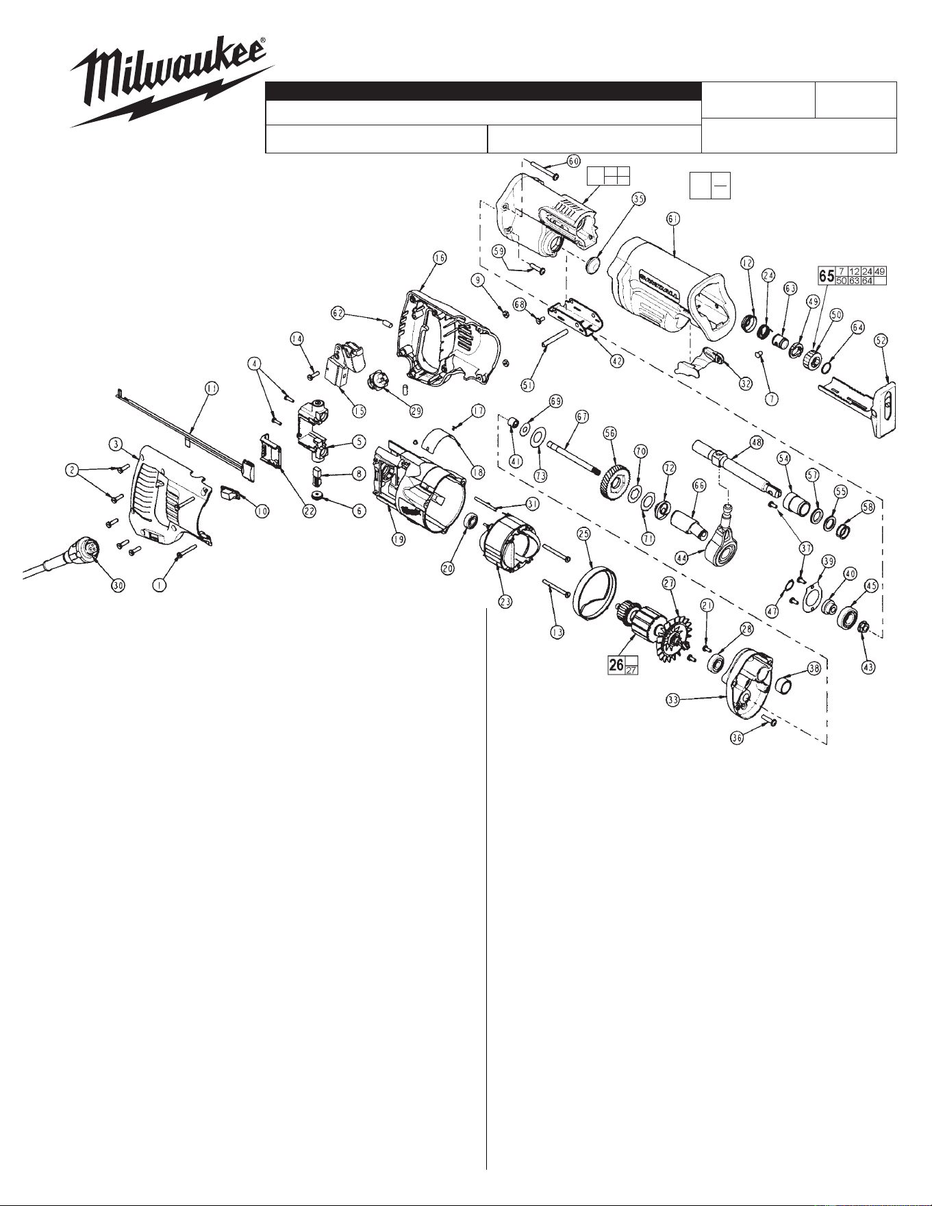
Component Parts (Small #)
Are Included When Ordering
The Assembly (Large #).
FIG. PART NO. DESCRIPTION OF PART NO. REQ.
1 06-82-2390 8-32 x 1-1/4" Slotted Pan Hd. T-20 Screw (2)
2 06-82-7270 8-16 x 5/8" Pan Hd. Plastite T-20 Screw (5)
3 31-44-1661 Right Handle Half (1)
4 06-82-7240 6-19 x 1/2" Pan Hd. Slt. Plastite T-15 Screw (2)
5 22-22-1385 Brush Holder Assembly (1)
FIG. PART NO. DESCRIPTION OF PART NO. REQ.
6 23-44-0125 Brush Retaining Cap (2)
7 44-60-0626 Lock Pin (1)
8 22-18-0926 Carbon Brush Assembly (2)
9 06-55-0835 Hex Nut (2)
10 31-53-0120 Plug (1)
11 14-20-3000 Remote Electronic Assembly (1)
12 31-15-0511 Spring Cover (1)
13 06-82-7410 8-16 x 1-7/8" Pan Hd. Plastite T-20 Screw (2)
14 06-82-7270 8-16 x 5/8" Pan Hd. Plastite T-20 Screw (1)
15 23-66-1965 Variable Speed Switch (1)
16 31-44-1666 Left Handle Half (1)
17 06-72-1710 Nameplate Rivet (2)
18 12-99-1765 Service Nameplate (1)
19 31-50-0020 Motor Housing (1)
20 02-04-0845 Ball Bearing (1)
21 06-82-7253 8-32 x 3/8" Pan Hd. Slt. Taptite T-20 (2)
22 43-72-0176 Heat Sink Holder (1)
23 18-31-0515 120 V. Field (1)
24 40-50-0161 Torsion Spring (1)
25 31-05-0055 Baffl e (1)
26 16-30-0570 120 V. Armature (1)
27 22-84-0531 Fan Assembly (1)
28 02-04-0915 Ball Bearing (1)
29 22-56-0840 Pin Housing Assembly (1)
30 48-76-4008 Quik-Lok Cord Set (1)
31 44-60-0530 Ground Pin (1)
32 31-52-0090 Shoe Release Lever (1)
33 28-28-1000 Diaphragm (1)
35 42-52-0380 Bearing Cap (1)
36 05-88-8309 K50 x 35mm Round Washer Hd. PT T-20 (1)
37 06-82-7253 8-32 x 3/8" Pan Hd. Slt. Taptite T-20 (2)
38 42-24-0620 Rear Spindle Bearing (1)
39 44-86-0055 Bearing Retainer (1)
40 45-36-1445 Spacer (1)
41 02-50-2150 Needle Bearing (1)
42 44-66-0880 Shoe Retainer (1)
43 06-55-3790 5/16-24 Spinlok Hex Nut (1)
44 30-72-0085 Wobble Plate (1)
45 02-04-1510 Ball Bearing (3)
46 34-80-2600 Internal Retaining Ring (1)
47 34-60-1315 Retaining Ring (1)
48 38-50-0500 Reciprocating Spindle (1)
54-40-5180
A18A
58-01-0277
SAWZALL
®
6519-22
FIG. PART NO. DESCRIPTION OF PART NO. REQ.
49 42-50-0077 Rear Cam (1)
50 42-50-0076 Front Cam (1)
51 44-60-1635 Shoe Pin (1)
52 45-16-0645 Shoe Assembly (1)
53 28-14-0996 Gear Case (1)
54 --------------- Front Spindle Bearing (1)
55 --------------- Felt Seal (1)
56 32-40-2050 Intermediate Gear (1)
57 --------------- Seal (1)
58 --------------- Washer (2)
59 06-82-5363 8-32 x 1" Washer Hd. Taptite T-20 (2)
60 05-88-0302 K50 x 60mm Round Washer Hd. PT T-20 (2)
61 45-12-0999 Gear Case Insulator (1)
62 14-46-1001 Foam Slug Kit - 10 Slugs (2)
63 45-22-0081 Sleeve (1)
64 34-60-3680 External Retaining Ring (1)
65 14-46-1011 Steel Quik-Lok Blade Clamp Kit (1)
66 36-92-0501 Wobble Shaft (1)
67 42-12-0155 Wobble Shaft Axel (1)
68 06-82-7253 8-32 x 3/8" Pan Hd. Slt. Taptite T-20 (1)
69 45-88-1555 Washer (1)
70 43-06-0685 Metal Plate (1)
71 43-06-0675 Bronze Plate (1)
72 43-78-0525 Drive Hub (1)
73 40-50-8850 Disc Spring (1)
SEE REVERSE SIDE FOR
IMPORTANT SERVICE NOTES
MILWAUKEE ELECTRIC TOOL CORPORATION
13135 W. LISBON RD., BROOKFIELD, WI 53005
Drwg. 6
REVISED BULLETIN DATE
SPECIFY CATALOG NO. AND SERIAL NO. WHEN ORDERING PARTS
SERVICE PARTS LIST
STARTING
SERIAL NO.
BULLETIN NO.
CATALOG NO.
WIRING INSTRUCTION
00
0
53
54 55
57 58
Aug. 2006
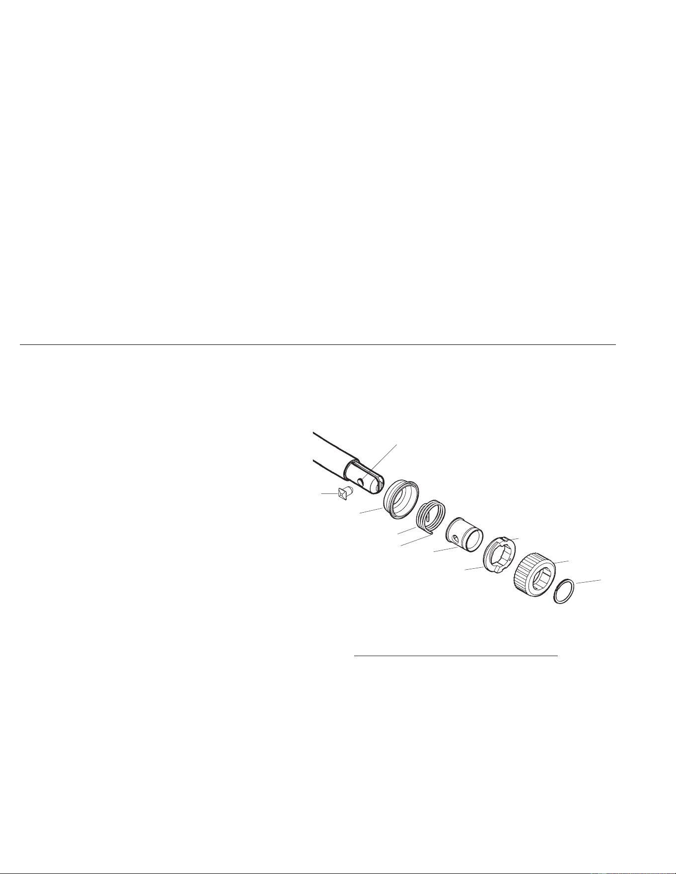
REMOVING THE STEEL QUIK-LOK
®
BLADE CLAMP
• Remove external retaining ring (64) and pull front cam (50) off.
• Pull lock pin (7) out and remove remainder of parts and discard.
REASSEMBLY OF THE STEEL QUIK-LOK
®
BLADE CLAMP
• Coat new lock pin with powdered graphite.
• Hold tool in a vertical position.
• Place spring cover (12) onto spindle.
• Slide torsion spring (24) onto spindle with spring leg on hole side of spindle.
• Slide sleeve (63) onto spindle aligning hole on sleeve with hole in spindle.
• Slide rear cam (49) over sleeve until it bottoms on sleeve shoulder, ensure spring leg inserts into hole in rear cam.
• Rotate rear cam in the direction of the arrows located on spring cover until there is clearance for lock pin (7) to be inserted
into sleeve/spindle holes. Insert lock pin.
• Align front cam (50) inner ribs with rear cam outer slots and slide front cam onto sleeve until it bottoms.
Retaining ring (64) groove should be completely visible.
• Attach retaining ring by separating coils and inserting end of ring into groove, then wind remainder of ring into groove.
Ensure ring is seated in groove.
• Blade clamp should rotate freely. During normal usage, debris may not allow blade clamp to rotate freely. The use of spray
lubricant can help free blade clamp. In extreme conditions, follow these instructions to remove, clean and reassemble blade
clamp.
FIG. LUBRICATION
53 Place 1/2 oz. of type "Y" grease, No. 49-08-5270, in gearing cavity near diaphragm.
53 Place 2-1/2 oz. of type "L" grease, No. 49-08-4175, in cavity in front of bearing plate.
FIG. NOTES
20 Seal side faces commutator.
20,28,41,45 Press bearings to shaft shoulders.
33,38 Press rear spindle bearing fl ush to -.030 from front exterior face in diaphragm boss.
43 Torque to 180 in./lbs. to 210 in./ lbs.
46,47 Retaining ring is to be installed with the beveled side away from the bearing.
53,54 Press front spindle bearing fl ush to .015 below exterior surface of gear case.
33,41 Needle bearing is to be pressed from the open end fl ush to -.015 to face of bearing boss of diaphragm.
62 After routing wires, place one foam slug in each location shown on the front page. Center slugs on screw bosses
and push down until fl ush with top of handle half.
(7)
(12)
(24)
(63)
(49)
(50)
(64)
Ensure drill point exists
in bottom of pin hole.
Leg
Outer Slot