
Technical Support and E-Warranty Certificate
www.vevor.com/support
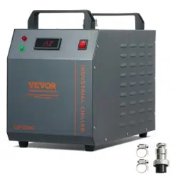
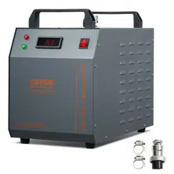
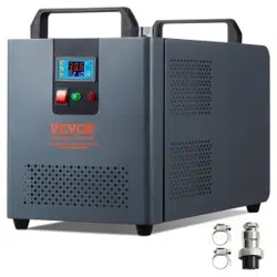
INDUSTRIAL WATER CHILLER
USER MANUAL
MODEL: KH-6000
We continue to be committed to provide you tools with competitive price.
"Save Half", "Half Price" or any other similar expressions used by us only represents an
estimate of savings you might benefit from buying certain tools with us compared to the major
top brands and does not necessarily mean to cover all categories of tools offered by us. You
are kindly reminded to verify carefully when you are placing an order with us if you are
actually saving half in comparison with the top major brands.

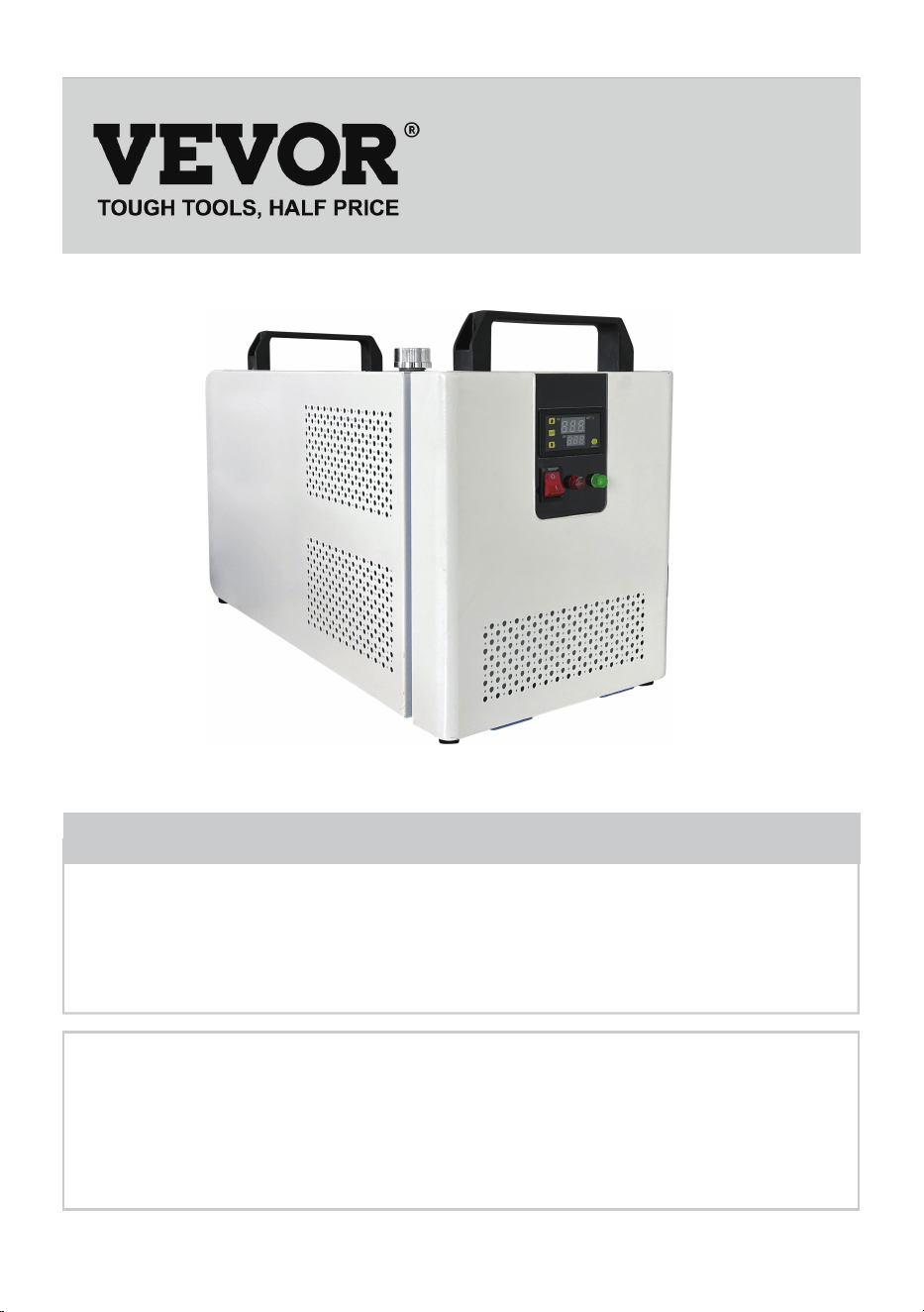
MODEL: KH-6000
(The picture is for reference only, please refer to the actual object)
Have product questions? Need technical support? Please feel free to
contact us:
Technical Support and E-Warranty Certificate
www.vevor.com/support
NEED HELP? CONTACT US!
This is the original instruction, please read all manual instructions
carefully before operating. VEVOR reserves a clear interpretation of our
user manual. The appearance of the product shall be subject to the
product you received. Please forgive us that we won't inform you again if
there are any technology or software updates on our product.
INDUSTRIAL WATER
CHILLER
-1-

WARN
Although the average working current of the chiller is small, the instantaneous working current can sometimes
reach 6~10 amperes (the instantaneous working current of the AC110V power supply model is possible up to
10~1 5 amperes)
PLEASE MAKE SURE THAT THE POWER SUPPLY AND THE POWER OUTLET ARE IN GOOD CONTACT
AND THE GROUNDING WIRE MUST BE FIRM!
PLEASE MAKE SURE THAT THE WORKING CHILLER HAS A STABLE AND NORMAL VOLTAGE!
Since the refrigeration compressor is more sensitive to power supply and voltage, so the working voltage our
standard product is 220^ 240V (110V model is 110 120V), if you really need a wider operating voltage range,
we can customize.
PLEASE MISMATCHED POWER FREQUENCY WILL CAUSE CHILLER DAMAGE!
Please select mode: 50Hz or 60Hz depending on the actual situation.
TO PROTECT THE PUMP, IT IS STRICTLY FORBIDDEN TO RUN THE CHILLER WITHOUT WATER IN THE
STORAGE TANK!
The new machine is packed after draining the entire water in the tank, so please make sure that the tank has
enough water and there is water inside the machine before starting, otherwise it is easy to damage the pump.
When the water level is below the green (normal) range of the water level gauge, the cooling capacity of our
chillers will drop slightly. Therefore, make sure that the water level is in the green (normal) range. Pumps are
strictly forbidden by circulating drainage!
PLEASE MAKE SURE THE AIR INLET AND OUTLET ARE WELL VENTILATED!
The air outlet from the obstacle to the back of the cooler must be at least 30 cm, and it should be at least 8 cm
between the obstacle and the side air intake.
THE FILTER MUST BE CLEANED REGULARLY!
The dust meter must be unlocked and cleaned, otherwise it will cause serious clogging failure to the cooler.
PAY ATTENTION TO THE EFFECT OF CONDENSATE!
As the ambient humidity increases, when the water temperature is lower than the ambient temperature,
condensate will create circular pipes and cooling parts on the water surface. If this occurs, it is recommended
to set a higher water temperature or keep the connected pipes and cooling components warm.
PROFESSIONAL USE ONLY!
This device must not be used by a child or a person with physical, sensory or physical, sensory, or physical
impairments, or lack of experience and knowledge, unless supervision or instruction is given, and the child is
not allowed to play with electrical appliances!
The circulating water of the water cooler must use a sealed container for normal use, such as laser tube cooling
water. Unsealed containers cannot circulate, such as water basins, buckets cannot be used for circulating
water cooling with water coolers.
-2-

Model KH-6000
AC220V
17kg
21kg
17.5kg
21.5kg
frequency
50Hz
AC110V
60Hz
0.13kw 0.2kw
power
500W
Cooling capacity
Refrigerant
noises
Water tank capacity
Maximum flow
Pump power
The main material
Security
R134a
≤65dB
12L
8L/min
30W
Iron, copper
Compressor overcurrent protection flow alarm
overtemperature alarm
voltage
color
net weight
gross weight
size
Package size
Blue-white
60*28.5*38 (mm)
67.5*41.5*46.5 (mm)
SPECIFICATIONS
-3-
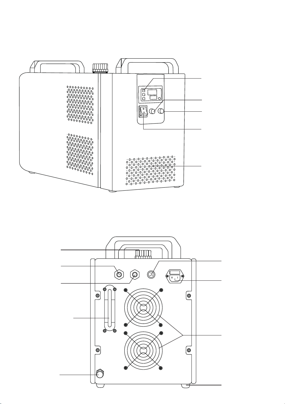
DEVICE ILLUSTRATION
front
behind
Temperature controller
Normal Flow (Red)
Normal Flow (Green)
Master switch
Air intake
Alarm output
terminal
Power outlets
Cooling fan
base
Drain spout
Water level
observation line
Water supply
inlet
Cooling
water inlet
Cooling
water outlet
-4-
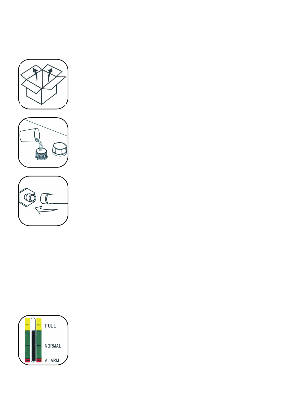
PROCEDURE
Installing this industrial chiller is very simple.
The first installation of a new machine can be carried out by following these steps:
The first start of the new cooler drains the air in the water pipe, causing a slight drop in the
water level, but in order to maintain the water level in the green area, it is allowed to add
enough water again. Please observe and record the current water level, check again after
the chiller has been running for a period of time, and if the water level drops significantly,
please re-check the leakage of the water pipe.
⑤.CHECK THE WATER LEVEL IN THE TANK.
CW-5000/5200 series uses intelligent thermostats. Usually the user does not need to adjust it. If it is really necessary.
See "Operating status and parameter tuning".
⑥.ADJUST THE TEMPERATURE CONTROLLER PARAMETERS.
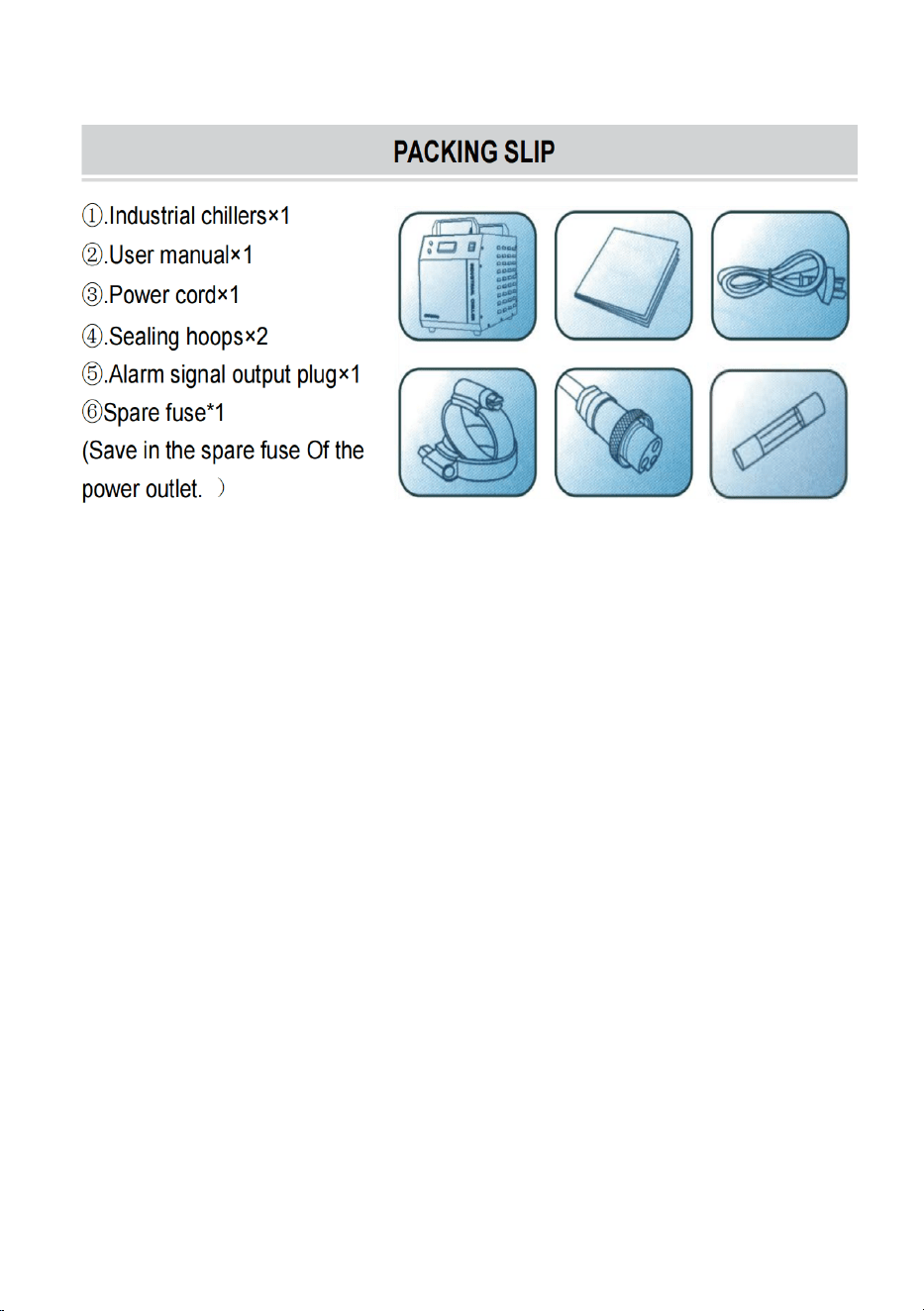
①.
OPEN THE PACKAGE TO CHECK IF THE MACHINE IS FIXED AND ALL NECES-
SARY ACCESSORIES ARE COMPLETE.
③.
CONNECT THE INLET AND OUTLET PIPES ACCORDING TO THE SYSTEM CONDI-
TIONS.
(1) The power switch is turned on and the circulating pump of the chiller starts to work. The first operation may
cause more bubbles in the pipe, causing occasional alarms for traffic, but after a few minutes of operation, it will
return to normal.
(2) After the first start-up, the water pipe must be checked for leakage immediately.
(3) The power supply is turned on, if the water temperature is lower than the set value, it is normal that the fan
and other parts of the machine do not work. The temperature controller will automatically control the working
state of compressor solenoid valves, fans and other components according to the set control parameters.
(4) Since the restart of the compressor and other components takes a long time, depending on different
conditions, the time varies from a few seconds to a few minutes, so do not turn off the power frequently and turn
it on again.
④.
PLUG IN THE POWER SUPPLY AND TURN ON THE POWER SWITCH. (DON'T START WITHOUT WATER IN
THE TANK!)
Observe the water level gauge and add water slowly, taking care not to let the water
overflow! For the cooling of carbon steel equipment, an appropriate amount of cooling
water additive (anti-corrosion water aqua) should be added to the water. Users in cold
regions should use non-corrosive antifreeze.
②.
OPEN THE WATER SUPPLY INLET TO SUPPLY COOLING WATER (DON'T SPILL
THE WATER OUT!).
-5-
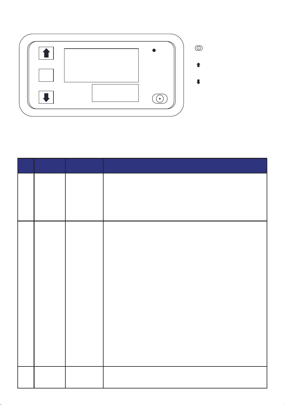
DISPLAY PANEL AND BUTTONS
INSTRUCTIONS FOR KEY OPERATION
Press the SET button 1 time to enter the time setting mode, and the red
digital tube flashes. Adjust the timing time T1 by pressing the key plus or
subtracting the key button, T1 is set and short press SET again, the green
digital tube flashes, the timing time is set by the key plus or minus T2, T2
time is set, short press the SET button again, the system will save the
memory when setting the question or Yuan Shoufu 0s, O5B for the tracing
brake to automatically remember and save the data.
Press and hold SET to enter the parameter setting mode. There are two
sets of parameters for users to select PO and P1. In the current mode,
short press SET to switch between P0 and P1. Under the PO parameters,
you can set the timing mode that suits you by pressing the button to add
or subtract. Under the P1 parameter, the working mode can be set by
pressing the button to add or subtract.
P0--0: T1 timing time mode is seconds
PO--1:T1 timing time mode is minutes
PO--2: T1 timer time mode is time
P1--0: relay pick-up after delay T1 time (T1 timing) P1-1: relay release
after delay T1 time (T1 timing) P1-2: relay pick-up after delay T1 time (T1
timing), relay release (T2 timing) after delay T2 time, end.
P1--3: Relay release (T1 timing) after delay T1 time, relay engagement
(T2 timing) after delay T2 time, and end.
P1-a4: Relay engagement (T1 timing) after delay T1 time, relay release
(T2 timing) after delay T2 time, and repeat cycle.
P1--5: Relay release after delay T1 time (T1 timing), relay engagement
after delay T2 time (T2 timing), repeat cycle.
For example, for example, a customer needs to turn on the computer for
10 seconds, turn off it for 20 seconds, and keep looping.
T1 setting time 10, T2 setting time 20PO-0 (T1 timing range is seconds)
P1-5 (the working mode of the timer is to work first and then stop and keep
looping)
Due to the wrong setting, the data is messed up, and when it cannot be
set, you can choose to restore the factory language and leave it on and
then power it on.
1
SORT KEYSTROKE FUNCTION
DESCRIPTION OF THE OPERATION
2
3
SET
▲+SET
SET
Time setting
mode
Parameterization
mode
Factory reset
8.8.8
8.8.8
SET
OUT
PV
SV
key:Move the key down
SETkey:Set the key
key:Reboot key
key:Adjust the up key
Before use, the user is first reminded to pay attention to a point, the data must be set and wait for 6s, and the module
will automatically save the data after 6s
-6-
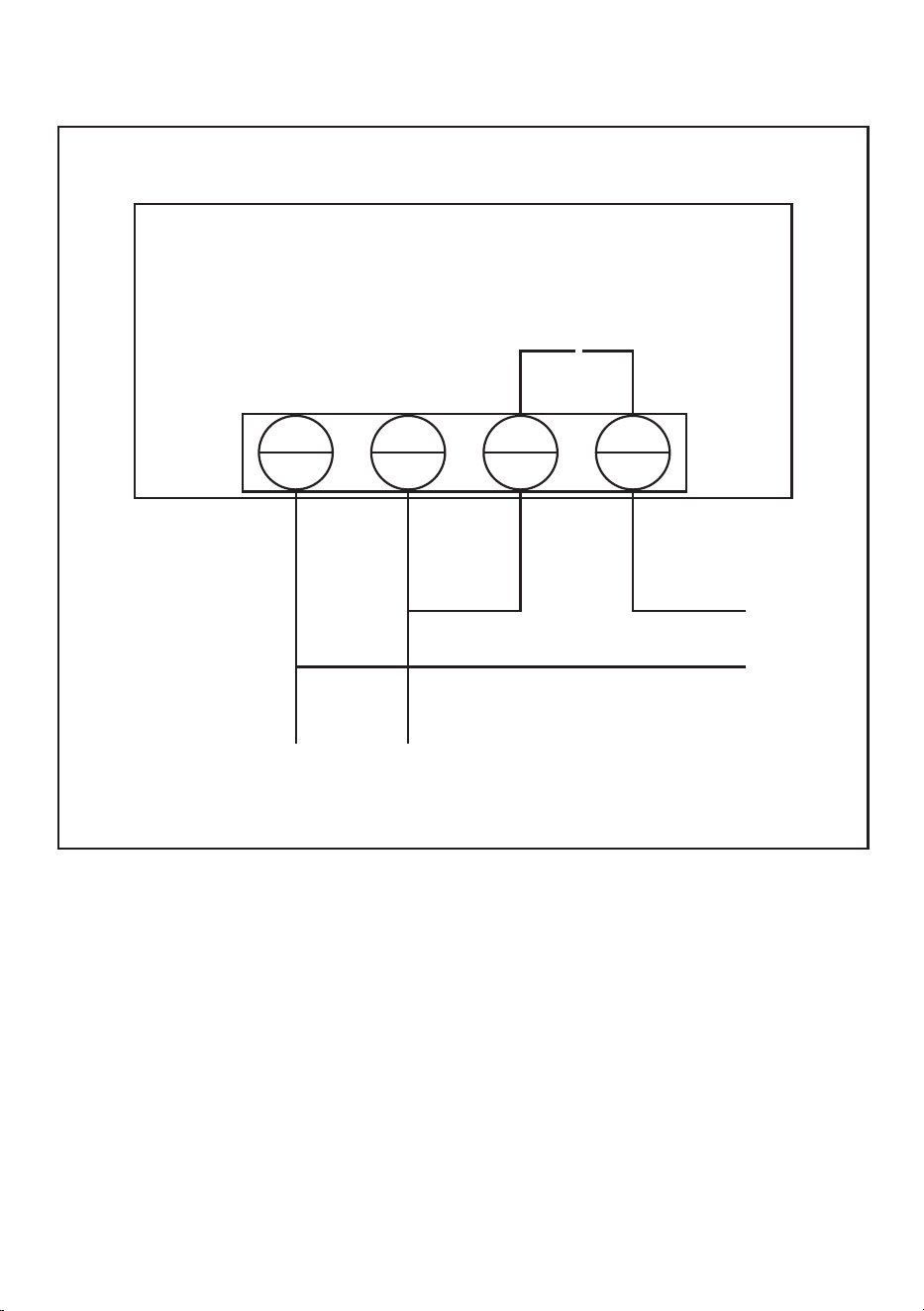
PRODUCT INTRODUCTION
S1
S2
L
+
N
-
110V-220V
load
Wiring(Commecting Mode)
Power supply(Suupply)
PRODUCT INTRODUCTION:
Time range: 0-999 hours/0-999 minutes/0-999 seconds
Display panel size: 79mm*43mm
Installation size: 71mm*40mm*24mm
Features: 18 combinations of time can be set
Relay: Original 20A relay, power < 1800W
Working voltage: DC 12V / DC 24V / AC 110V-220V (optional)
RELAYS ARE AVAILABLE IN 3 OPERATING VOLTAGE SPECIFICATIONS:
DC 12V/DC 24V/AC 110V-220V 2200W
You can choose to buy according to your actual situation, and if you don't know how to wire or
don't know how to choose, you can contact customer service for advice
-7-


Technical Support and E-Warranty Certificate
www.vevor.com/support