54-24-0380
1/2" HAMMER-DRILL
A68A
Feb. 2009
5387-20
58-01-0127
REVISED BULLETIN
SERVICE PARTS LIST
BULLETIN NO.
WIRING INSTRUCTION
DATE
CATALOG NO.
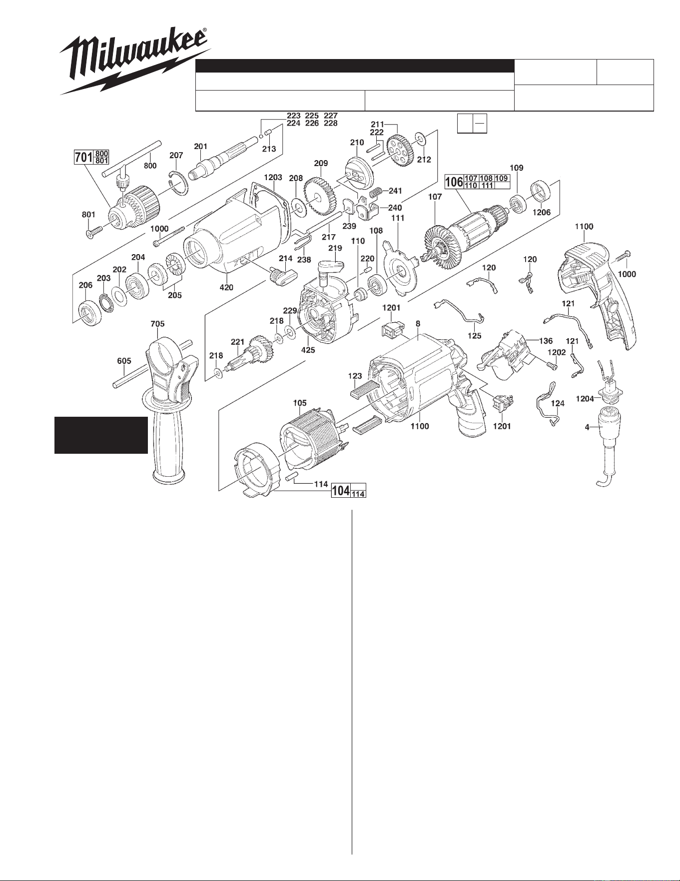
SPECIFY CATALOG NO. AND SERIAL NO. WHEN ORDERING PARTS
SERIAL
NUMBER
MILWAUKEE ELECTRIC TOOL CORPORATION
13135 W. LISBON RD., BROOKFIELD, WI 53005
Drwg. 3
FIG. PART NO. DESCRIPTION OF PART QTY.
4 48-76-5010 QUIK-LOK CORD SET 1
8 12-99-5381 SERVICE NAMEPLATE 1
104 42-14-0115 AIR DEFLECTION RING 1
105 18-07-0121 FIELD 1
106 16-07-0124 ARMATURE ASSEMBLY 1
107 22-84-0940 FAN 1
108 02-04-0063 BALL BEARING 1
109 02-04-0064 BALL BEARING 1
110 45-22-0055 SLEEVE 1
111 42-92-0145 BEARING COVER 1
114 45-30-0210 VINYL SLUG 4
120 23-94-0041 WIRE ASSEMBLY - BLACK 2
121 23-94-0042 WIRE ASSEMBLY - BLACK 2
123 42-70-1100 FIELD CENTERING CLIP 2
124 23-94-0043 WIRE ASSEMBLY - RED 1
125 23-94-0044 WIRE ASSEMBLY - RED 1
136 23-66-0034 SWITCH 1
201 38-50-0100 SPINDLE 1
202 45-88-8295 WASHER 1
203 40-50-8890 VIBRATION SPRING 1
204 02-04-1830 BALL BEARING 1
205 44-84-0295 RATCHET (SET OF 2) 1
206 44-90-0004 SEAL RING 1
207 44-90-0019 RETAINING RING 1
208 45-88-1300 WASHER 1
209 32-75-0045 SPINDLE GEAR 1
210 44-90-0065 SHIFT RING 1
211 32-75-0055 SPINDLE GEAR 1
212 45-88-0335 WASHER 1
213 44-60-1490 PIN 1
214 44-10-0025 SHIFT LEVER 1
217 44-60-1470 PIN 1
218 45-88-8345 THRUST WASHER 2
219 44-10-0035 SHIFT LEVER 1
220 44-60-1480 PIN 1
221 32-60-0065 REDUCTION GEAR 1
222 44-60-1475 PIN 2
223 02-02-0105 BALL - 3.4mm 1
FIG. PART NO. DESCRIPTION OF PART QTY.
224 02-02-0125 BALL - 3.6mm 1
225 02-02-0155 BALL - 3.7mm 1
226 02-02-0115 BALL - 3.8mm 1
227 02-02-0160 BALL - 3.9mm 1
228 02-02-0110 BALL - 4.0mm 1
229 45-88-0315 WASHER 1
238 40-50-0150 RETAINING SPRING 1
239 42-70-0085 SHIFTING CLIP 1
240 42-70-0090 SHIFTING CLIP 1
241 40-50-0335 PRESSURE SPRING 1
420 31-40-0095 GEARCASE 1
425 28-28-0025 DIAPHRAGM ASSEMBLY 1
605 43-46-0172 DEPTH GAGE 1
701 48-66-0087 1/2" CHUCK (INCLUDES #800) 1
48-66-4040 CHUCK KEY HOLDER (NOT SHOWN) 1
705 49-15-5300 SIDE HANDLE 1
800 48-66-3280 CHUCK KEY 1
801 05-80-0430 6MM LH SCREW 1
1000 14-46-0030 BOLT KIT (3 BOLTS REQUIRED) 1
1100 14-38-0145 HOUSING w/BACK HANDLE 1
1200 14-46-0020 MAINTENANCE SET (NOT SHOWN)
(INCLUDES TUBE TYPE 'E' GREASE) 1
1201 22-16-0065 CARBON BRUSH SET (2 PER PKG) 1
1202 05-81-0932 SCREW 2
1203 45-06-0025 SEAL 1
1204 22-56-0050 BLADE HOUSING ASSEMBLY 1
1206 45-22-0540 RUBBER SLEEVE 1
FIG. NOTES:
106,1100,1206 RUBBER SLEEVE (BEARING CUP) TO BE PLACED
INTO MOTOR HOUSING ASSEMBLY PRIOR TO
INSTALLING ARMATURE ASSEMBLY.
111,220 DEMPLE IN BEARING COVER TO FACE PIN.
209,210 FLATS OF SHIFT RING TO FACE SPINDLE GEAR.
223-228 THE CORRECT SIZE BALL MUST BE CHOSEN TO
PROPERLY SHIM OUT THE END PLAY IN THE
SPINDLE. SPINDLE IS TO HAVE A SMALL AMOUNT
OF END PLAY WITHOUT BEING TIGHT.
EXAMPLE:
Component Parts (Small #) Are Included
When Ordering The Assembly (Large #).
0
00
SEE REVERSE SIDE
FOR SERVICE &
GREASE NOTES
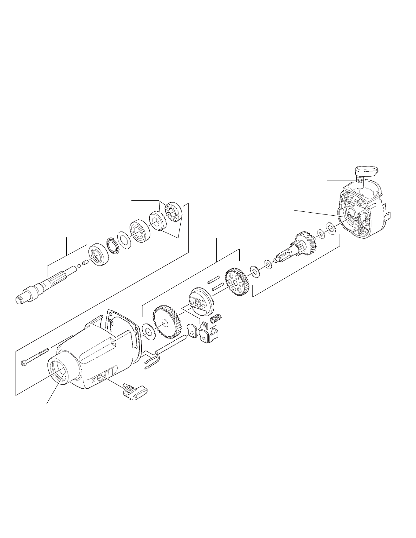
5387-20 SERVICE AND GREASE NOTES
See Note 3
1/16 oz. Type "E"
See Note 5
3/8 oz. Type "E"
See Note 4
1/8 oz. Type "E"
See Note 6
Greasing Instructions
Type "E" Grease, No. 49-08-4122 (Included in Maintenance Set No. 14-46-0020)
Type "U" Grease, No. 49-08-0150
1. Clean ratchets faces (205) completely and apply a light coat of type "U" grease, No. 49-08-0150.
2. Place 1/16 oz. of type "E" grease, No. 49-08-4122, in and around the ratchet cavity of the gearcase (420).
Other than the mating faces, lightly coat the ratchets (205) with Type "E" Grease, No. 49-08-4122.
3. Coat spindle splines (201), pin (213) and ball (223-228) with 1/16 oz. of type "E" grease, No. 49-08-4122.
4. Place 1/8 oz. of type "E" grease, No. 49-08-4122, in gear cavity of diaphragm (425).
5. Grease gear assembly (parts 208, 209, 210, 211, 212, 217, 218, 221, 222, 229, 239, 240 and 241) using 5/8 oz.
type "E" grease, No. 49-08-4122.
6. Using type "E" grease, No. 49-08-4122, lightly grease O-ring on Item (219) before assembly to gearcase.
Total amount of type "E" grease: approximately 1 oz.
See Note 2
See Note 1
Lightly coat with Type "U"
See Note 2
1/16 oz. Type "E"
See Note 5
1/4 oz. Type "E"