
1
User Manual
8K 8×8 Matrix with Ultrawide, 40Gbps Bandwidth Input and Output Stages
AC-MX-88X
1

2
INTRODUCTION ������������������������������������������������������������������������������������������������������4
FEATURES ���������������������������������������������������������������������������������������������������������������4
WHATS IN THE BOX ������������������������������������������������������������������������������������������������4
SPECIFICATIONS �����������������������������������������������������������������������������������������������������5
FRONT AND REAR PANEL OVERVIEW ����������������������������������������������������������������������6
INITIAL SETUP: WEBUI �������������������������������������������������������������������������������������������7
ADVANCED SETUP: WEBUI INPUT SETTINGS - EDID ��������������������������������������������� 10
ADVANCED SETUP: GLOBAL INPUT SETTINGS ������������������������������������������������������ 11
ADVANCED SETUP: WEBUI VIDEO OUTPUT SETTINGS ������������������������������������������ 11
ADVANCED SETUP: WEBUI EXTRACTED AUDIO OUTPUT SETTINGS ��������������������� 12
WEBUI: VIDEO MATRIX ����������������������������������������������������������������������������������������� 15
WEBUI: AUDIO MATRIX ����������������������������������������������������������������������������������������� 16
WEBUI: I/O CONFIG - INPUT SETTINGS ���������������������������������������������������������������� 17
WEBUI: I/O CONFIG - INPUT SETTINGS CONT ������������������������������������������������������ 18
WEBUI: I/O CONFIG - OUTPUT SETTINGS ������������������������������������������������������������� 19
WEBUI: I/O CONFIG - OUTPUT SETTINGS CONT ��������������������������������������������������� 19
WEBUI: I/O CONFIG - OUTPUT SETTINGS CONT ��������������������������������������������������� 20
WEBUI: I/O CONFIG - OUTPUT SETTINGS CONT ��������������������������������������������������� 21
WEBUI: SYSTEM - IP SETTINGS ����������������������������������������������������������������������������� 22
WEBUI: SYSTEM - TELNET SETTINGS �������������������������������������������������������������������� 23
WEBUI: SYSTEM - ADMIN WEB INTERFACE ����������������������������������������������������������� 23
WEBUI: SYSTEM - USER WEB INTERFACE �������������������������������������������������������������� 24
WEBUI: SYSTEM - CLOUD SERVICES ���������������������������������������������������������������������� 25
WEBUI: SYSTEM - FIRMWARE UPDATE CONT �������������������������������������������������������� 26
WEBUI: SYSTEM - HARDWARE ������������������������������������������������������������������������������� 26
WEBUI: DIAGNOSTICS - HDMI IN �������������������������������������������������������������������������� 27
WEBUI: DIAGNOSTICS - HDMI IN CONT����������������������������������������������������������������� 28
WEBUI: DIAGNOSTICS - HDMI OUT ����������������������������������������������������������������������� 29
WEBUI: CONSOLE �������������������������������������������������������������������������������������������������� 30
2

33
FRONT PANEL CONTROL - SWITCHING ����������������������������������������������������������������� 31
FRONT PANEL CONTROL - EDID ��������������������������������������������������������������������������� 32
FRONT PANEL CONTROL - AUDIO ������������������������������������������������������������������������� 33
FRONT PANEL CONTROL - NETWORK ������������������������������������������������������������������� 33
IR CONTROL: IR REMOTE �������������������������������������������������������������������������������������� 34
IR CONTROL: EXTENSION PORT ���������������������������������������������������������������������������� 34
RS-232 AND TCP/IP CONTROL ������������������������������������������������������������������������������� 35
COMMAND LIST ���������������������������������������������������������������������������������������������������� 36
COMMAND LIST CONTINUED: ������������������������������������������������������������������������������ 37
COMMAND LIST CONTINUED: ������������������������������������������������������������������������������ 38
EXTRACTED AUDIO ����������������������������������������������������������������������������������������������� 39
BALANCED 5 PIN 2CH AND TOSLINK AUDIO PORT /SPDIF ����������������������������������39V
AUDIO OUTPUT LOGIC AND CABLE PREP ������������������������������������������������������������� 40
TROUBLESHOOTING ���������������������������������������������������������������������������������������������� 41
BANDWIDTH CHART ��������������������������������������������������������������������������������������������� 42
BANDWIDTH CHART CONTINUED ������������������������������������������������������������������������� 43
MAINTENANCE ����������������������������������������������������������������������������������������������������� 44
DAMAGE REQUIRING SERVICE ������������������������������������������������������������������������������ 44
SUPPORT ��������������������������������������������������������������������������������������������������������������� 45
WARRANTY ����������������������������������������������������������������������������������������������������������� 45

4
Introduction
Simply stated, the AVPro Edge AC-MX-88X is a classic transformed into an icon. Our engineers focused on
re-imagining the venerable AC-MX-88, boosting bandwidth to an ultrawide 40Gbps with 8K input and output
stages, for a world-rst, Next-Gen 8 input / 8 output matrix switching platform providing a foundation for all
possibilities that follow. “X ” marks the spot for high performance that is unmistakably AVPro Edge, as we
once again redene the face of the HDMI switching era. Gaming enthusiasts, rejoice - multiple inputs for
multiple consoles! Select Xbox Series X, PlayStation 5, or your Alienware Aurora Ryzen by control system or
from the supplied IR remote and leave the cable juggling to Cirque du Soleil.
The AC-MX-88X, designed with the needs of Next-Gen users in mind, prepares your clients for tomorrow’s
over-the-near-horizon signals, while ultrawide bandwidth supplies sure-footed dynamic headroom for
hiccup-free performance with HDMI 2.1a devices. With the unmatched pedigree of AVPro Edge behind it
tradition never fails, as the AC-MX-88X lets you break convention and seek perfection.
Features
· HDMI Specication HDMI 2.1a
· HDCP 2.3 (and all earlier versions supported)
· Up to 8K 60Hz 4:2:0 / 8K 30 Hz 4:4:4, 60-120fps
· 4K 120Hz, 120fps
· 8K to 4K or 8K/4K to1080p Down Scaling on all outputs
· Balanced Analog Audio Outputs (2 CH PCM)
· Full HDR Support (HDR 10 & 12 Bit)
· Dolby Vision, HDR10+ and HLG Support
· Advanced EDID Management
· IR, RS-232 and LAN Control Option
· Driver Support for C4, Crestron, Elan, RTI, Savant, URC
and more
· NOTE: 8K Ultra-wide Bandwidth Necessitates the Use
of Active Optical Cables for Distances Over 4 Meters.
Please see Bullet Train Cables for Length Options.
Whats in the box
· 1× AC-MX-88X (Matrix Switch)
· 1× 48V 3.75A Power Supply
· 1× IR Remote Control
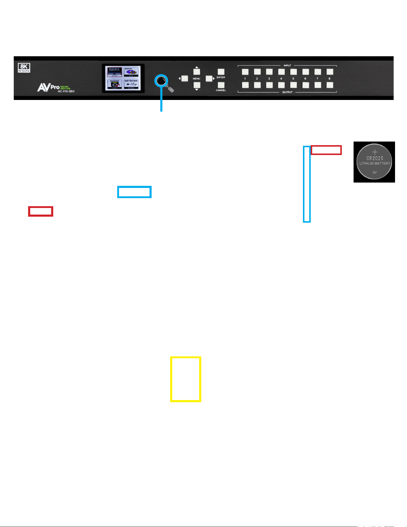
· 1× CR2025 Battery for IR Remote
· 1× IR Extension Cable
· 8× 5pin Terminal to L/R adapter cables
for 2ch Extracted Audio
· 1× 3pin terminal block (for RS-232)
· 2× Mounting Brackets (Installed)
· 1× Ground strap
· 4× Matrix Feet with hardware
*3V CR2025 Battery Required For IR Remote Control
1× Included in the packaging.
4
NOTE TO DESIGNERS, INSTALLERS, AND TECHNICIANS
When used with an AVR or a Pre-processor as an HDMI video bypass around outdated onboard AVR or Pre-processor HDMI video signal
technology, especially when introducing a Next-Gen video display into a system while retaining an existing AVR or Pre-processor that remains
compatible with current immersive audio codec reproduction, the following must be noted: When the main HDMI video display output of the
bypassed AVR or Pre-processor is left untethered to an EDID-producing device, the AVR or Pre-processor has no means for EDID negotiation or
authentication. As a result, source devices fail to detect an active EDID-managed HDMI path. An AVR or Pre-processor may not fully activate or
switch to the desired input for audio capture if no active output is detected or fails to enable proper input signal processing.
BEST PRACTICE is for the AVR or Pre-processor to terminate into a device that produces an active EDID, which serves to “trick” the AVR or Pre-
processor into continuing to function as designed (with a video signal and multi-channel audio selected at one of its inputs, expected to transfer the
video signal to a display device with EDID authentication). An AVPro Edge AC-SC-1X or AC-DA12-AUHD-GEN2 with EDID management is ideal for
overcoming this anomaly as both have EDID management capabilities; however, any device capable of producing an EDID compatible with
maintaining the AVR’s or Pre-processor’s stability may be utilized.
5
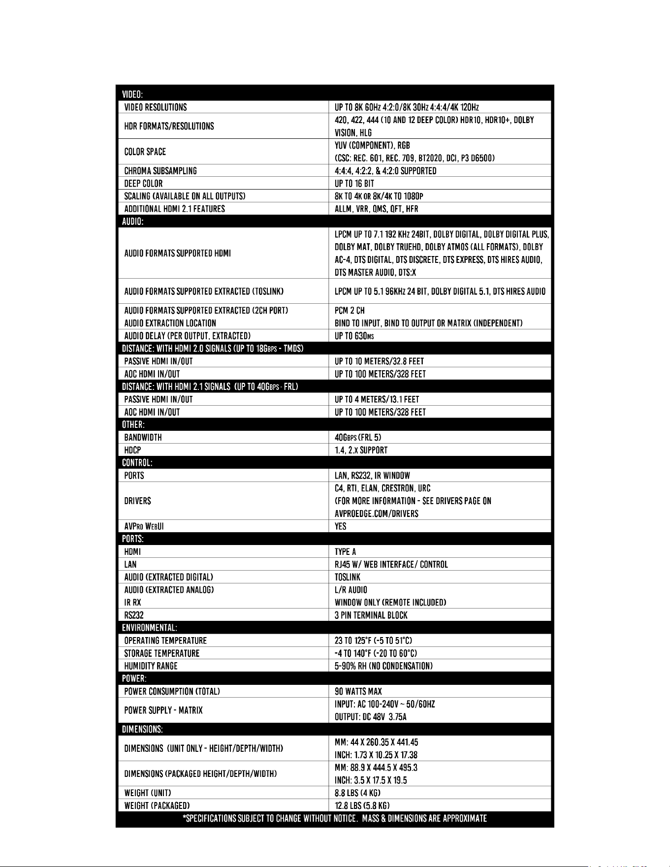
Specications
5
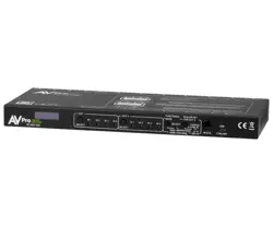
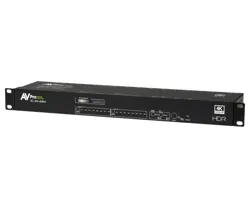
6
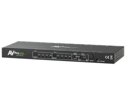
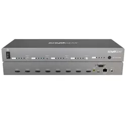
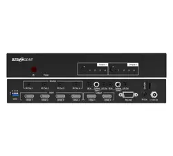
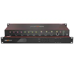
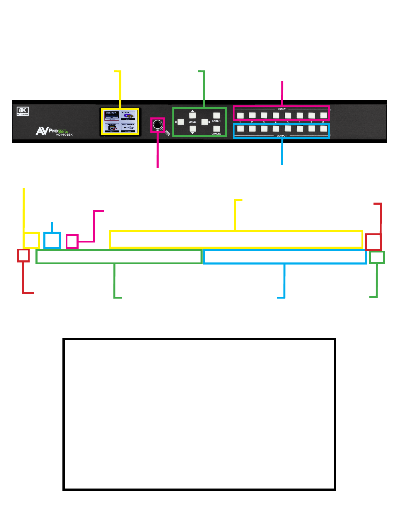
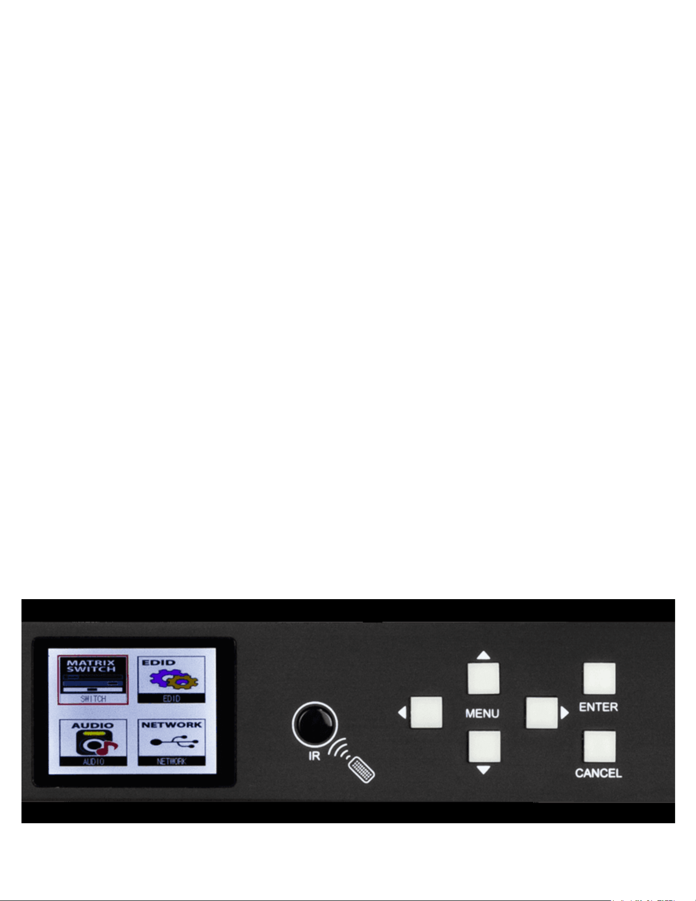
Front and Rear Panel Overview
6
Input Select
Button
Front Panel
Display
Navigation
Buttons
IR Eye
Output Select
Buttons
LAN Connection
Extracted
Audio
48V
Power
USB-C
ISP/Control
HDMI
Outputs
HDMI
Inputs
3pin
RS-232
Control
3.5mm IR
Extension
Ground
Strap
7
Initial Setup: WebUI
1. With the AC-MX-88X placed into its new home (AV Rack, cabinet, table top) take a Phillips head
screwdriver and attach the included yellow ground strap to the back of the chassis using the pre-installed
screw, then attach the other end to a suitable grounded object.
2. Connect the HDMI Input sources to the HDMI Inputs on the back of the matrix.
3. Connect the HDMI/devices to the HDMI Outputs.
4. Connect the network LAN cable to the RJ45 port labeled LAN (next to 3pin RS232 port above grounding screw).
5. Power on the sources (Inputs).
6. Power on the Output devices/displays.
7. Connect the 48V power supply to power on the matrix and then to a suitable power source.
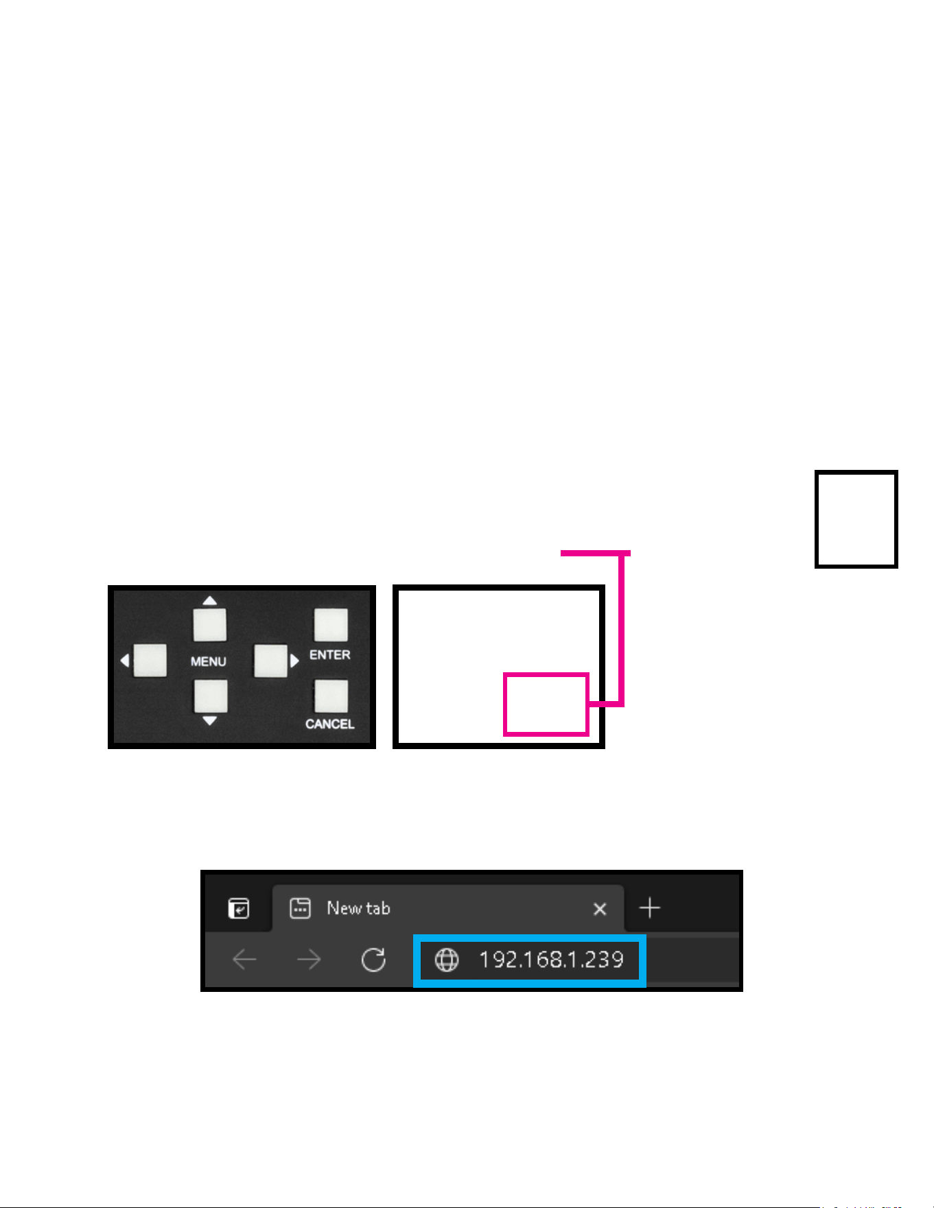
8. Using the front panel display and Menu navigation buttons navigate to NETWORK and press the ENTER
button to enter the IP Settings menu.
9. Either manually enter in your desired IP settings, or enable DHCP and let your network assign the correct settings. Use
the UP/DOWN arrow keys to highlight the row you want to change (HIP, RIP, TCP Port, etc), click , use left/right arrow
keys to select and the UP/DOWN arrow keys to change the setting. Click the OK button again to conrm those changes.
10. With the matrix connected to the local network, using a computer on the same network open up a web browser and type
the HIP (Host IP Address) into the address bar to navigate to the WebUI.
The AC-MX-88X can be controlled using the USB-C port, 3pin RS232, or over TCP/IP using the LAN connection. For initial setup
it is recommended to connect the matrix to a local area network (LAN) and use a computer on the same network in conjunction
with the built in WebUI. After making all the physical connections, the rst step will be to check for any Firmware Updates.
The below steps are an example of this setup, other control options are covered in separate sections of this user manual.
7
8
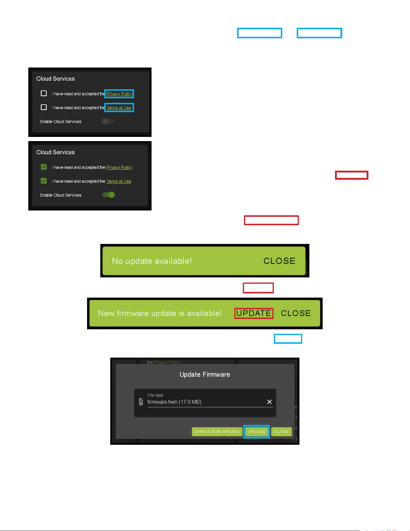
11. With the AVProEdge WebUI open, navigate to System. Click on the Privacy Policy and Terms of Use, this will open
these documents in a new tab for review. Once read click on the boxes next to each to agree. When both are checked
the switch for Enable Cloud Services will be selectable (will be red or disabled by default). Click to enable (the switch will
turn green).
12. With the Cloud Services enabled under the Hardware section click the Update Firmware button to check for new
Firmware OTA (over the air). This will compare the rmware versions currently loaded on the AC-AXION-X and compare
to the latest available. If it is up to date, you will see a prompt stating “No update available!”
13. If an update is available, the following prompt will show. Simply click UPDATE.
14. If a new update is available a le will automatically be selected, simply click the UPLOAD button to load the rmware
les to the Matrix. Uploading does not install the Firmware, that is the next step.
9
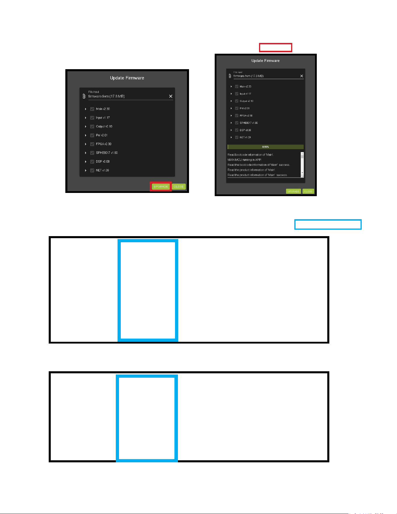
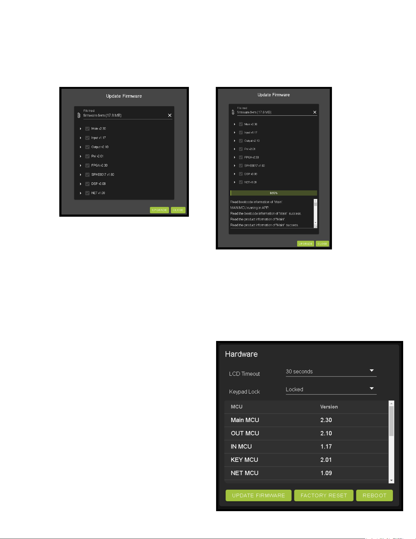
15. Once the rmware le has been uploaded, it will display all containing rmware les. Here you can select individual
rmware les to load or simply leave all les/options selected. If the version currently installed is not newer (does not
need to be updated), then that update will be skipped automatically. Click the UPGRADE button to start.
16. Once the progress bar hits 100% click the CLOSE button, the rmware upgrade process is complete.
17. With the Firmware up to date it’s time to start setting up the matrix. With the AVProEdge WebUI open, navigate to the
I/O Conifg section. Label the applicable Inputs (Apple TV, Cable Box, Roku, etc) under the Input Settings - Label.
18. If an Input is not being used, you can click the Enabled switch o (it will turn red).
19. Label the Outputs (Living Room, Bedroom, Den, etc) under the Video Output Settings - Label.

10
20. Set the HDMI Video Scaling if needed. Each HDMI OUTPUT has a drop-down
with x3 options for scaling.
21. With the system and all it’s components powered up it’s time to verify signal path from source to the sync. For now leave
EDID settings to their default 1080P 2CH, the next section Advanced Setup will cover the more advance settings.
22. Use the Signal Indicator on the HDMI INPUTS. Green means HDMI source is detected,
red means that the source is not detected. If red verify that the input is powered on
and that the HDMI cable is properly connected to the source and to the back of the
matrix.
23. Now verify the connections to the HDMI outputs using the Signal indicator. Green means HDMI sync is detected, red
means that the HDMI sync is not detected. If red verify that the sync devices are powered on and that the HDMI cables
are properly connected to the back of the matrix.
24. With everything connected and powered on, green indicators across the applicable inputs and outputs, verify you are
getting all of your sources on all of your displays.
25. Problems with a source or sync, see the Troubleshooting section for help on page[s] 41.
Advanced Setup: WebUI Input Settings - EDID
After verifying good signal path from source to sync now it is time to go through the rest of the settings to maximize the setup.
Starting on the input side with the EDID.
• No Scaling (default) - No scaling will be applied to that output.
• 4K to 1080P - Any signal above 1080P will be down-scaled to 1080P
• 8K to 4K - Any signal above 4K will be down-scaled to 4K
1. With the WebUI open, navigate to the I/O Conifg tab and focus on the Input Settings section at the top.
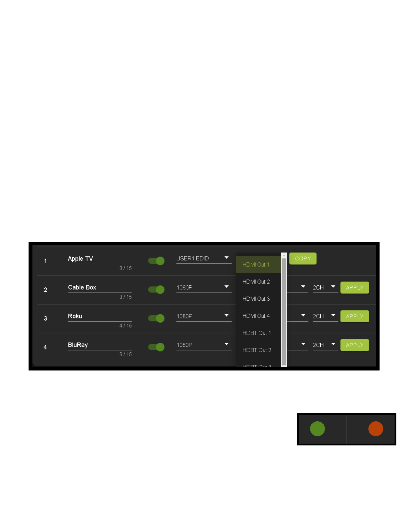
2. Set the EDID on each input by selecting the resolution drop-down rst (default is set to 1080P). The options are 1080P,
4K30Hz, 4K60Hz Y420, 4K60Hz, and FRL10G8K. If you select USER1 EDID, then the drop-downs change to allow you to
select from an output to copy from. You can select any of the 8 HDMI
outputs then click the COPY button. This will save that outputs EDID
to the USER1 slot.
3. Next use the drop-down to select NO 3D, or 3D depending on the
displays capability.
NOTE: Currently the only resolution you can choose NO 3D for is 1080P.
4. Next drop-down select either SDR (standard dynamic range) or HDR
(High Dynamic Range).
5. The fourth drop-down in the EDID section is for the audio, you can
select 2CH, 6CH, or 8CH.
6. Click the button to set the EDID.
7. Verify you are still getting that source to all your displays and that the image looks correct.
NOTE: Some older displays may take an HDR signal and display correctly (ignoring the HDR Metadata)
others will not ignore the HDR part of the signal and may display incorrectly.

11
· Support Dolby MAT - Check this box to enable Dolby MAT audio.
· Require Dolby Vision Low Latency - Check this box to require Dolby Vision Low Latency (Player-led) over Standard
Dolby Vision (TV-Led). Sources like the Apple TV and X-Box Series X use Dolby Vision Low Latency.
Advanced Setup: Global Input Settings
Under the Input settings is a section called Global Input Settings. These two settings apply to all eight of the HDMI Inputs.
Default these are both o (unchecked) but depending on the system both of these may need to be check for optimum
performance. Check the specications on the devices in the signal chain to verify compatibility/support.
Advanced Setup: WebUI Video Output Settings
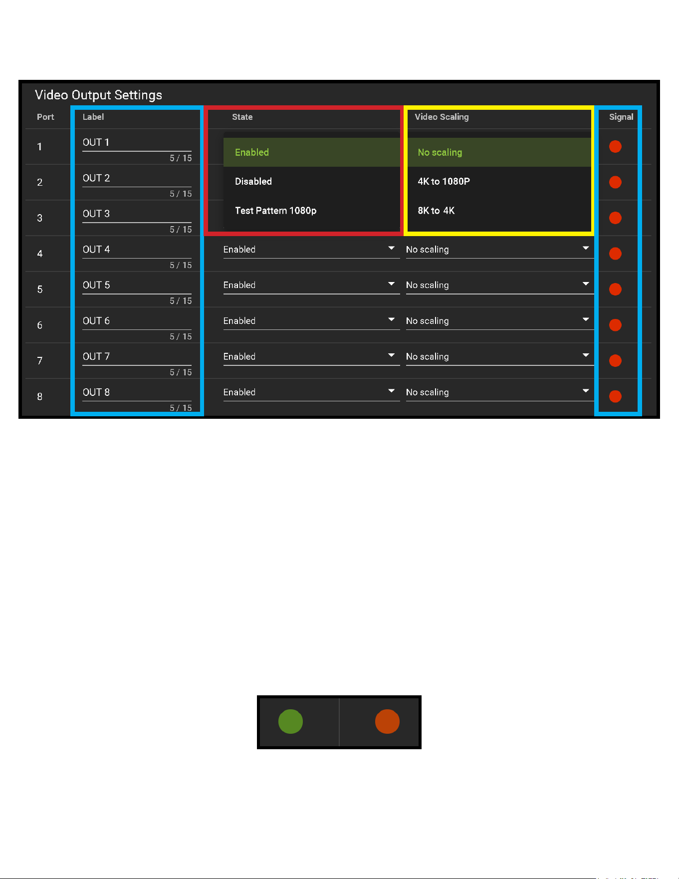
1. Now navigate to the Video Output Settings under I/O Cong
2. In addition to the output Label (name/alias), there State and Video Scaling Settings for each HDMI output.
3. Under State there are 4 options.
· Enabled (Default) - HDMI Port is on (normal functionality)
· Disabled - HDMI Output Port will not output a signal
· Test Pattern 1080P - Enables a 1080P Colorbar test pattern on that port
· Test Pattern 4K - Enables a 4K Colorbar test pattern on that port
12
Advanced Setup:
WebUI Extracted Audio Output Settings
1. Now navigate to the Extracted Audio Output Settings under I/O Cong.
2. The extracted audio ports have 3 distinct operating modes, use the drop-down at the top to select. The three options
are.
4. Under the Video Scaling mode you can choose Auto, No Scaling (o), 4K to 1080P, or 1080P to 4K.
5. Signal - The Signal Indicator on the HDMI outputs shows the current state of the
connected HDMI device. Green means HDMI signal is detected, red means that the
signal is not detected. If red verify that the HDMI cable is properly connected to both
the matrix and HDMI sync device.
· Auto - Will automatically scale based on the connected syncs EDID
· No Scaling (Default) - Signal remains untouched
· 4K to 1080P - Down-scales any 4K signal down to 1080P
· 4:4:4 to 4:2:0 - Will convert any 4K Signal (with a Video Clock above 500MHz) with YUV 4:4:4 and convert it to
YUV 4:2:0.
· Bind to Input (Default) - where the audio port number corresponds to the input signal. This is ideal for
systems where audio is matrixed separately in a zoned amplier.
· Bind to Output - this conguration the audio will automatically follow the HDMI output. This is ideal for systems
that use local AVR’s for some of the Zones.
· Matrix - This mode allows you to matrix the extracted audio ports independently from the HDMI outputs. In this
mode there will be a Tab for the extracted audio under the Matrix page, allowing you to route the audio just like
routing the video. If the matrix is set to Bind to Input or Bind to Output this tab will not be visible.
13
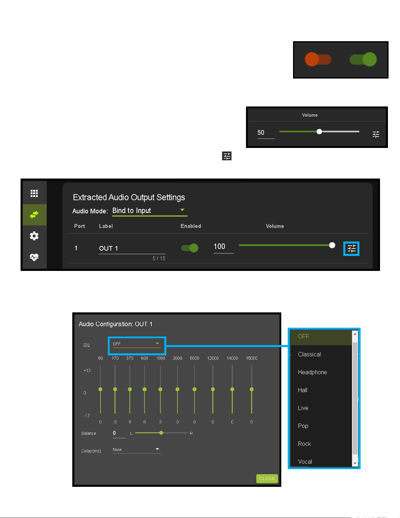
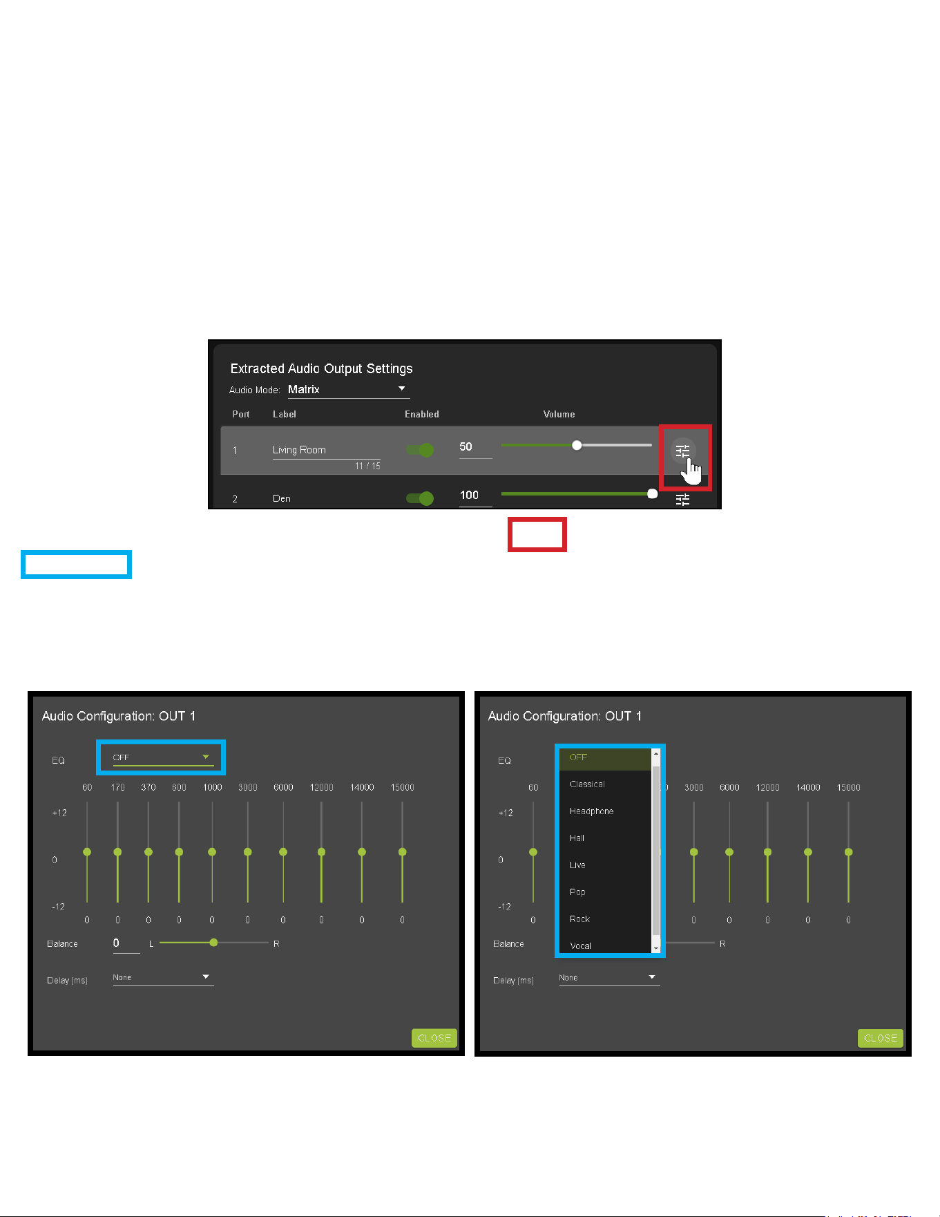
3. Other available settings for the extracted audio ports include
4. You can use the slider or text box to change the volume
(settings are 0-100).
5. To change the EQ settings of that port click on the emblem ( ) to the right of the volume slider. This will bring
up the Audio Conguration Page. Here you can choose from 8 dierent EQ settings, change the Left / Right balance, and
set the audio delay.
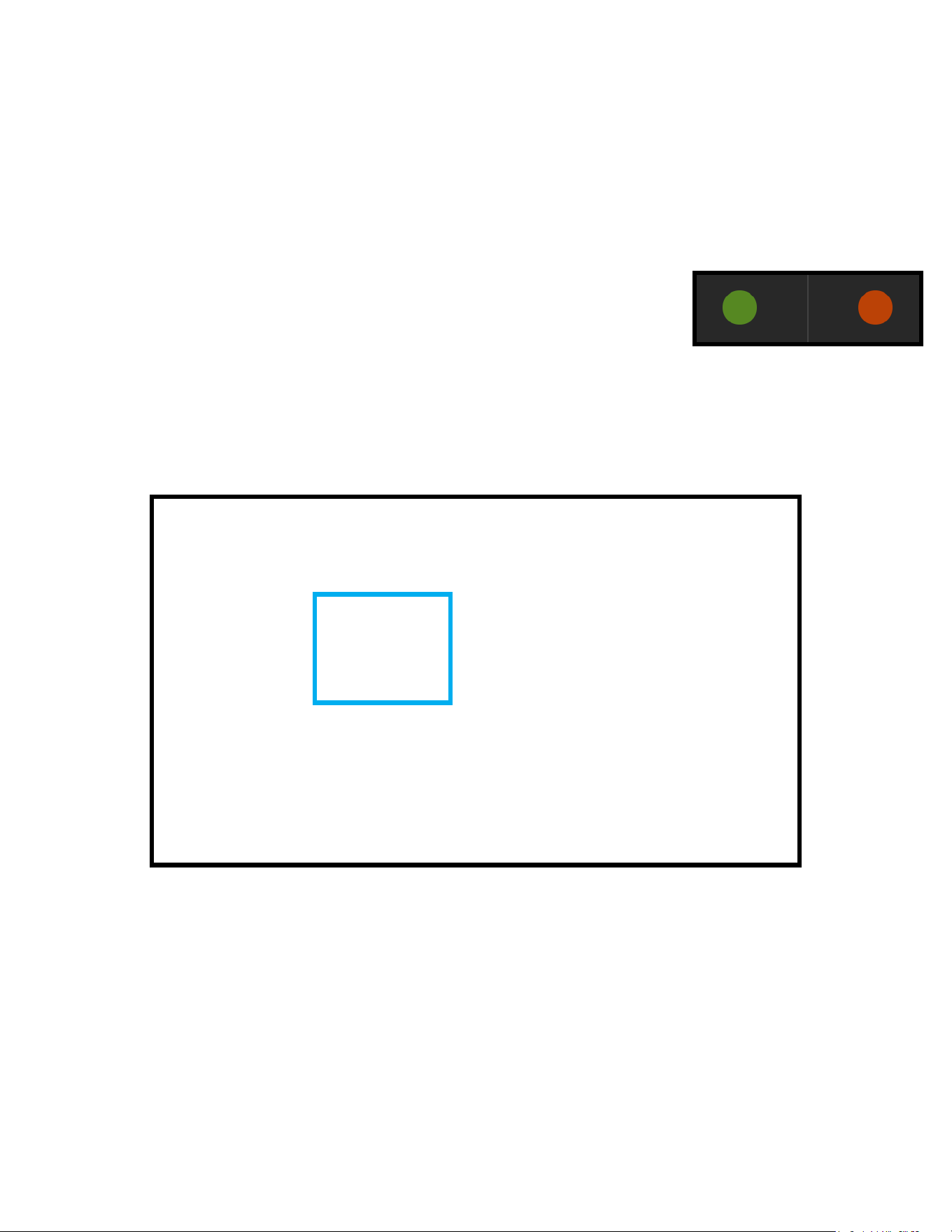
· Enable/Disable Switch
· Volume control (1-100) - Enter a numbered value, or use the slider bar to adjust
· EQ presets (7 generic preset options to choose from)
· Left/Right balance
· Audio Delay. Each of these 5 settings can be changed per extracted audio port.
O
Disabled
On
Enabled
14
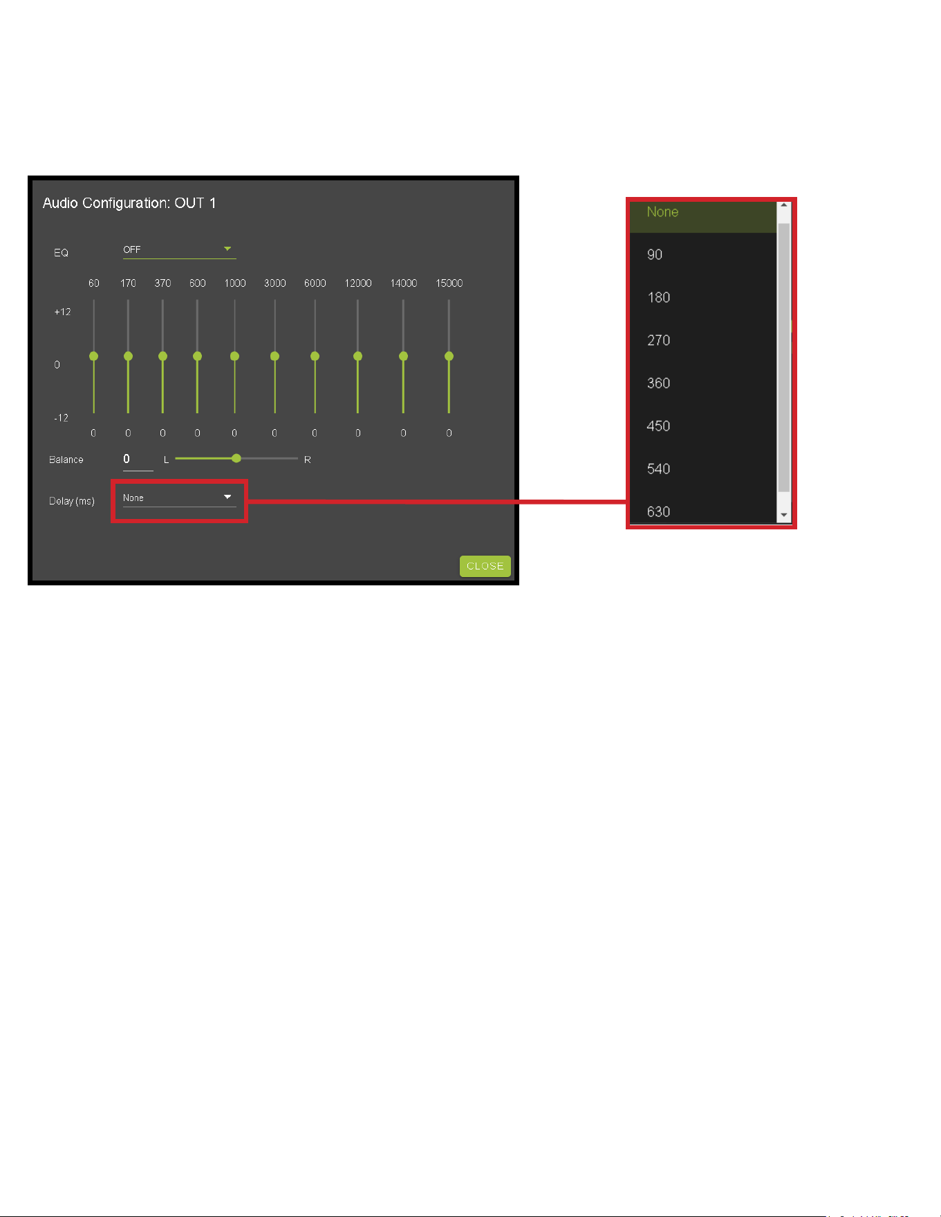
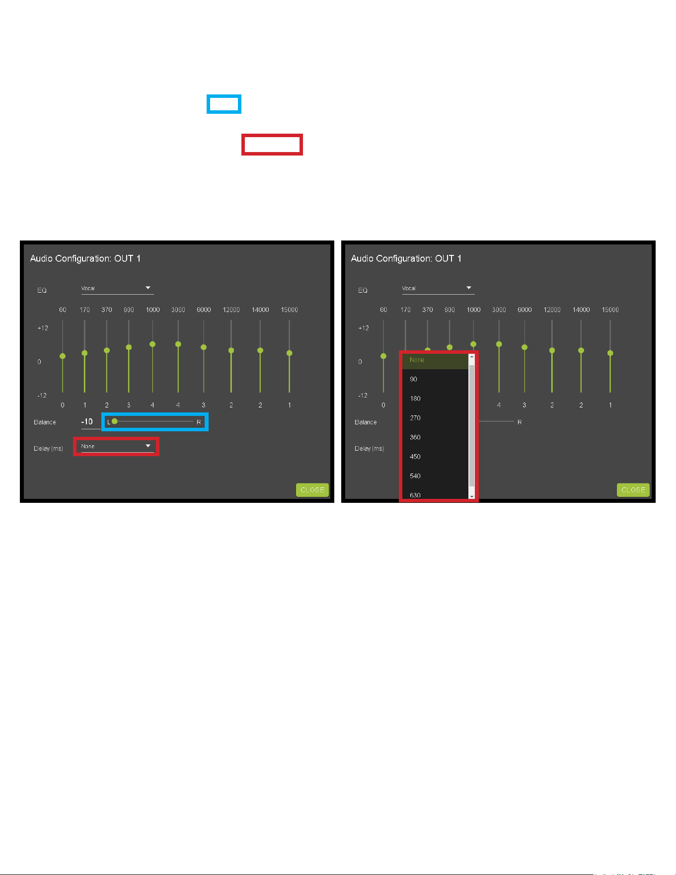
6. Delay (eight settings in 90 millisecond increments)
None (default), 90, 180, 270, 360, 450, 540, and 630.

15
WebUI: Video Matrix
Use this page to route the video INPUTS and OUTPUTS.
· Click on the INPUT number to select (example below shows IN 1)
· With the INPUT selected simply click on the OUTPUT you want to send that source to.
· Note: If you rename the INPUTS/OUTPUTS using the I/O Cong page they will display here.
16
WebUI: Audio Matrix
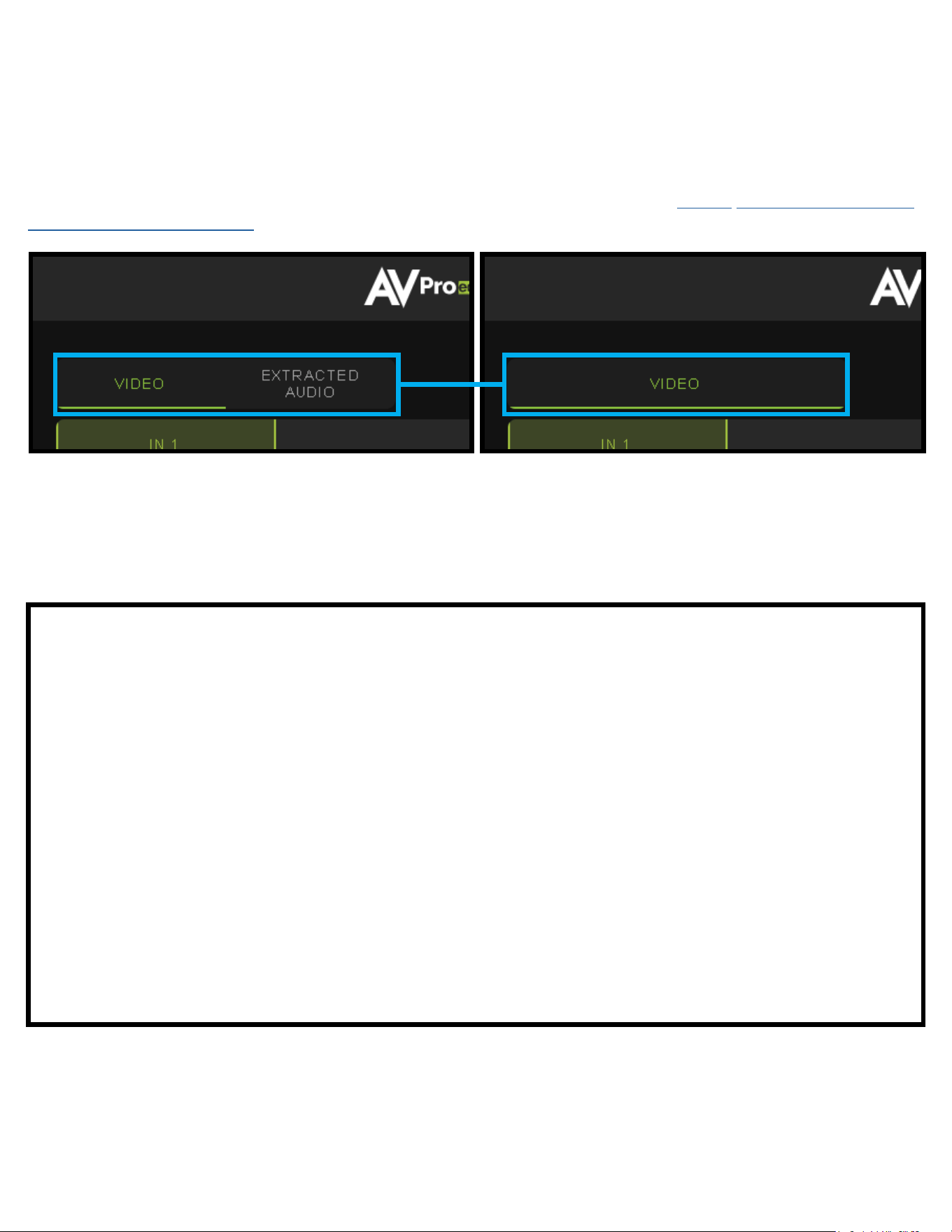
Use this page to route the extracted audio.
NOTE: The extracted audio ports can only be manually changed (matrixed) when in Matrix Mode. If the extracted audio is set to
Bind to Input (default) or Bind to Output then this tab will not be visible, example below. See Page 14 “Advanced Setup: WebUI
Extracted Audio Output Settings” for more info.
· Click on the INPUT number to select (example below shows IN 1 - Apple TV)
· With the INPUT selected simply click on the OUTPUT you want to send that audio to.
· Note: If you rename the INPUTS/OUTPUTS using the I/O Cong page they will display here.

17
WebUI: I/O Cong - Input Settings
Input Settings Label - Use this to give an name/alias to your inputs (Apple TV, Cable Box, Roku, etc). Note: There is a 15
character limit to this eld, the name will replace the default “IN #” throughout the rest of the WebUI (for instance the Video
Matrix tab).
Input Settings Enable switch - Use this enable/disable switch to turn the corresponding Input
port on or o. The default setting is enabled (green) by default.
O
Disabled
On
Enabled
18
WebUI: I/O Cong - Input Settings Cont
Input Settings Signal - The Signal Indicator on the HDMI INPUTS shows the current state of the connection HDMI
source. Green means the HDMI source is detected, red means that the source is not detected. If red verify that source is
powered on and that the HDMI cable is properly connected to the source and to the back of the matrix.
Global Input Settings - There are two settings available
· Supports Dolby MAT - Check this box to enable Dolby MAT audio
· Requires Dolby Vision Low Latency - Check this box to require Dolby Vision Low Latency
(Player-led) over Standard Dolby Vision (TV-Led). Sources like the Apple TV and X-Box Series X use Low Latency.
1. 1080P_2CH
2. 1080P_6CH
3. 1080P_8CH
4. 1080P_3D_2CH
5. 1080P_3D_6CH
6. 1080P_3D_8CH
7. 4K30HZ_3D_2CH
8. 4K30HZ_3D_6CH
9. 4K30HZ_3D_8CH
10. 4K60HzY420_3D_2CH
11. 4K60HzY420_3D_6CH
12. 4K60HzY420_3D_8CH
13. 4K60HZ_3D_2CH
14. 4K60HZ_3D_6CH
15. 4K60HZ_3D_8CH
16. 1080P_2CH_HDR
17. 1080P_6CH_HDR
18. 1080P_8CH_HDR
19. 1080P_3D_2CH_HDR
20. 1080P_3D_6CH_HDR
21. 1080P_3D_8CH_HDR
22. 4K30HZ_3D_2CH_HDR
23. 4K30HZ_3D_6CH_HDR
24. 4K30HZ_3D_8CH_HDR
25. 4K60HzY420_3D_2CH_HDR
26. 4K60HzY420_3D_6CH_HDR
27. 4K60HzY420_3D_8CH_HDR
28. 4K60HZ_3D_2CH_HDR
29. 4K60HZ_3D_6CH_HDR
30. 4K60HZ_3D_8CH_HDR
NOTE: If you select USER1 EDID, then drop-downs change to allow you to select from and output to copy from. You can select
any of the 4 HDMI outputs then click the COPY button (this replaces the Apply button). This will save that outputs EDID to the
USER1 slot.
In order to obtain Dolby Atmos, DTS:X, or other HBR Surround formats, the EDID must be copied from a capable device.
Input Settings EDID - Use these four drop-downs to select your preferred EDID.
The available combinations are as follows.
19
Output Settings Label - Use this to give an name/alias to your outputs (Living Room, Den, Kitchen, etc).
Note: There is a 15 character limit to this eld, the name will replace the default “OUT #” throughout the rest of the WebUI (for instance the
Video Matrix tab).
Output Settings State - This drop-down has 3 settings, just like the input settings you can Enable or disable this port. In
addition you can also choose Test Pattern to enable a 1080P color bar test pattern on that output. This is helpful in verifying the
signal chain from Matrix to sync (display). To disable the test pattern, change the state back to Enabled (default).
Output Settings Video Scaling - The HDMI outputs each have 3 settings. No scaling (scaling is o), 4k to 1080P, and 8k to 4k.
WebUI: I/O Cong - Output Settings
WebUI: I/O Cong - Output Settings Cont.
Output Settings Signal - The Signal Indicator on the HDMI OUTPUTS shows the current state of the connection HDMI Output.
Green means HDMI sync is detected, red means that the sync is not detected. If red verify that the output is powered on and
that the HDMI cable is properly connected to the sync and to the back of the matrix.
20
WebUI: I/O Cong - Output Settings Cont.
Output Settings Label - Use this to give an alias/name to your extracted audio outputs.
Note: There is a 15 character limit to this eld, the name will replace the default “OUT #” throughout the rest of the WebUI (for
instance the Video Matrix tab).
Output Settings Enabled - This is an enable/disable switch. By default this will be Enabled/Green. To change the setting
simply click to switch. Disabled/Red there will be no Audio passed on that extracted audio port (both Toslink and balanced 5pin
will be muted).
Output Settings Volume - Here you can use the slider bar to adjust the extracted port volume (0~100). You can also use the
text box and enter a value (0~100).
Output Settings EQ Settings - To open the EQ Settings click on the symbol next to the Volume slider.
EQ Drop-down contains 8 settings. The default o, Classical, Headphone, Hall, Live, Pop, Rock, and Vocal.
21
WebUI: I/O Cong - Output Settings Cont.
Output Settings Balance - Use this slider to adjust the Left/Right balance.
Note: Default is 0 (zero), value can be -10~10
Output Settings Delay (ms) - Audio delay drop-down has eight available settings, these are measured in milliseconds.
None (default), 90ms, 180ms, 270ms, 360ms, 450ms, 540ms, and 630ms.
22
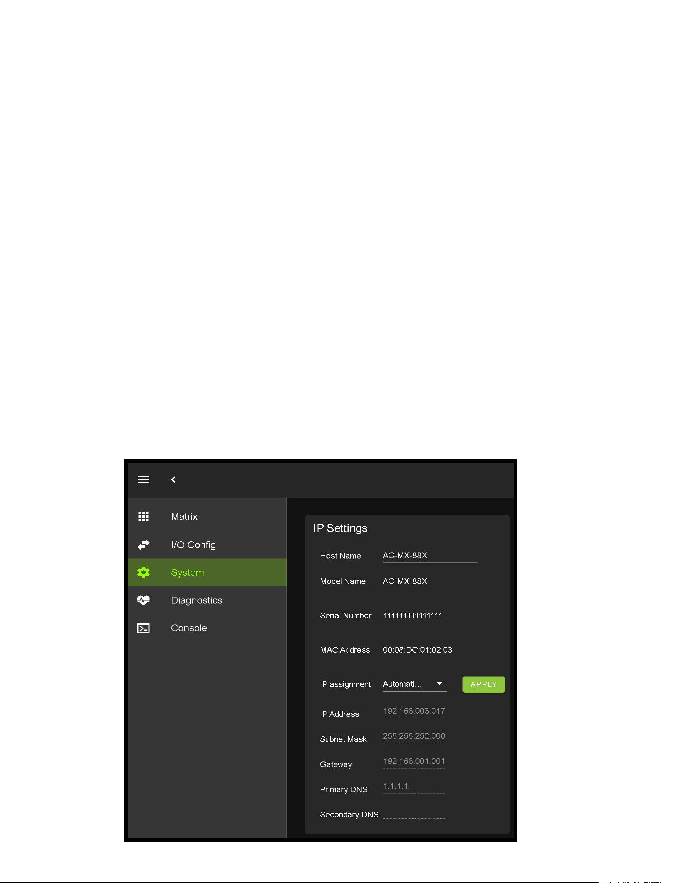
WebUI: System - IP Settings
Host Name - Devices name on the network. This eld is automatically lled with Model Name by default.
Model Name - Displays the AVProEdge Model/Part number.
Serial Number - Displays the Serial Number of the matrix.
MAC Address - Displays the devices MAC Address.
IP assignment - This drop-down has two options.
Manual
Automatic (DHCP)
Default out of the box will be set to Automatic (DHCP), the IP Address, Subnet Mask, Gateway, Primary DNS, and Secondary DNS
will be assigned by your network controller. If you select Manual, you can use the text elds to enter your own Network settings.
Once all elds have been lled out, click the green Apply Button to set. A prompt will appear to conrm the change, click OK to
conrm.
This area contains relevant network information of the AC-MX-88X.
23
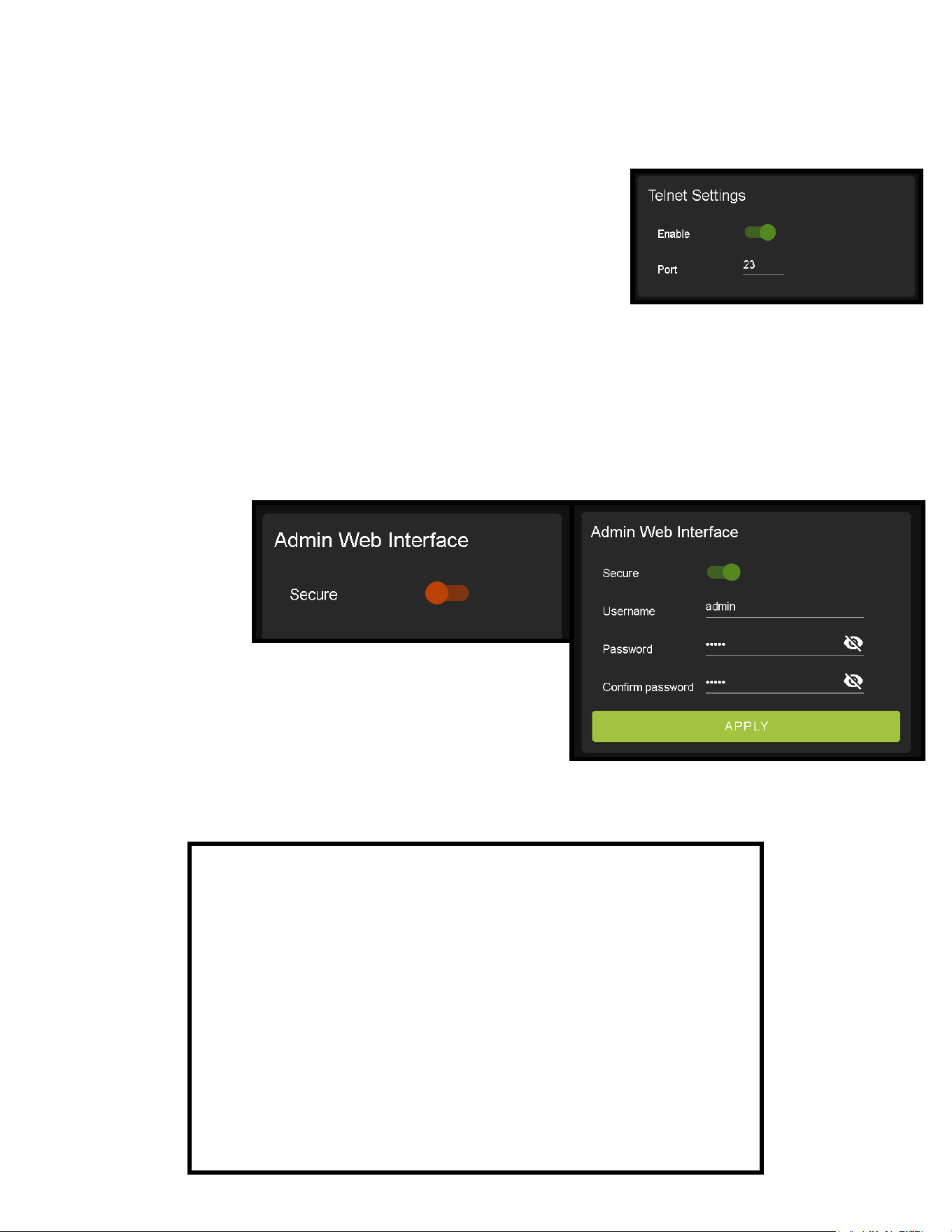
WebUI: System - Telnet Settings
This area contains relevant Telnet settings for the AC-MX-88. There are two elds that can changed, Enable Disable switch and
the Port Number.
· Enable - This switch has two options, Green/Enabled (Default) and Red/
Disabled.
· Port - This eld is used to change the Telnet Port of the AC-MX-88. You can
use the text led to enter a number or use the Up/Down arrow buttons to
increase/decrease the number.
WebUI: System - Admin Web Interface
This switch has two options, Red/Disabled (Default) and Green/Enabled. When enabled (green) there will be three elds that
appear, Username, Password, and Conrm Password.
Default Username - admin
Default Password - admin
Once the desired Username and
Password has been entered,
click the green APPLY button to
set.
With the Admin Web Interface enabled, the only menu that will be accessible
using the WebUI will be the Matrix tab. The rest of the settings will require
the Admin log in to access.
24
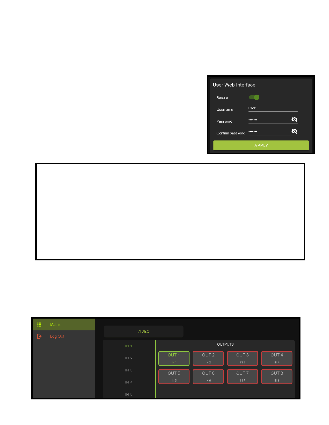
WebUI: System - User Web Interface
This switch has two options, Red/Disabled (Default) and Green/Enabled. When enabled (green) there will be three elds that
appear, Username, Password, and Conrm Password.
NOTE: The Admin Web Interface must rst be Enabled and setup before this eld will be available to change.
Default Username - user
Default Password - user123
Once the desired Username and Password has been entered, click the green APPLY
button to set.
Note: The web page will reload to the Log In page.
With both Admin and User Web Interfaces enabled, no menus will be accessible
using the WebUI without rst logging in (see image below).
Logging in with the User credentials, the only menu that will be accessible will be the Matrix tab. The rest of the settings will
require the Admin user to log in (see page 24).
25
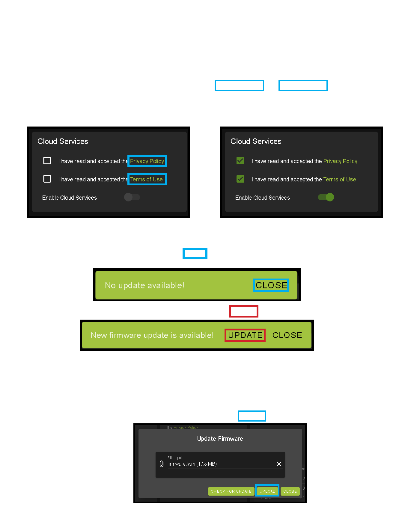
WebUI: System - Cloud Services
By enabling Cloud Services your device will have the ability to connect to rmware servers for over-the-air (OTA) updates and
enable third-party remote management services. If Cloud Services are disabled, your device will opt-out of any previously
enabled services and will not be able to access OTA updates.
Before you can enable the cloud services you must rst agree to the “Privacy Policy” and “Terms of Use”.
You can view these documents by clicking on Privacy Policy or Terms of Use links, this will open up a PDF copy of that document
in a new tab.
With the Cloud Services enabled you can use the System tab to check for new Firmware OTA (over the air).
This will check the rmware versions currently loaded on the AC-MX-88 and compare to the latest available. If it is up to date,
you will see a prompt stating “No update available!” click CLOSE to exit.
If an update is available a le will automatically be selected, simply click the UPLOAD button to load the rmware les to the
Matrix.
NOTE: When loading rmware (depending on the rmware les that are being updated) some settings will revert back to Factory
Defaults. Take note of the I/O Cong tab. Settings like the INPUT/OUTPUT labels, EDID Settings, Video Scaling, Audio Settings,
etc. as they will have to be re-applied after the rmware updates are completed.
If an update is available, the following prompt will show. Simply click the UPDATE button to load.
26
WebUI: System - Hardware
LCD Timeout - This adjusts the time the front panel display will stay lit up when a button is pressed.
There are four setting available
Always on (Default)
15 Seconds
30 Seconds
45 Seconds
WebUI: System - Firmware Update Cont.
Once the rmware le has been uploaded, it will display all containing rmware les. Here you can select individual rmware
les to load or simply leave all les/options selected. If the version currently installed not newer, then that update will be skipped
automatically.
Once the progress bar hits 100% click the CLOSE button, the rmware upgrade process is complete.
Now you will want to go back and re-apply settings like INPUT/OUTPUT Labels, applied EDIDs, Video Scaler Settings, Audio
Settings, etc.
Keypad Lock - Enable or Disable (default) the front panel Keypad
Lock.
MCU/Version - Lists the current Firmware Versions
UPDATE FIRMWARE - Check/upload rmware.
FACTORY RESET - Restores matrix to Factory Defaults
REBOOT - Reboots the AC-MX-88

27
WebUI: Diagnostics - HDMI IN
Input Settings Label - Use this to give an name/alias to your inputs (Apple TV, Cable Box, Roku, etc).
Note: There is a 15 character limit to this eld, the name will replace the default “IN #” throughout the rest of the WebUI (for
instance the Video Matrix tab).
Input Settings Enable switch - Use this enable/disable switch to turn the corresponding Input
port on or o. The default setting is enabled (green) by default.
Connection Reset - Use this button to perform a reset of the HDMI Input connection.
Input Settings EDID - Use these four drop-downs to select your preferred EDID.
The available combinations are as follows.
1. 1080P_2CH
2. 1080P_6CH
3. 1080P_8CH
4. 1080P_3D_2CH
5. 1080P_3D_6CH
6. 1080P_3D_8CH
7. 4K30HZ_3D_2CH
8. 4K30HZ_3D_6CH
9. 4K30HZ_3D_8CH
10. 4K60HzY420_3D_2CH
11. 4K60HzY420_3D_6CH
12. 4K60HzY420_3D_8CH
13. 4K60HZ_3D_2CH
14. 4K60HZ_3D_6CH
15. 4K60HZ_3D_8CH
16. 1080P_2CH_HDR
17. 1080P_6CH_HDR
18. 1080P_8CH_HDR
19. 1080P_3D_2CH_HDR
20. 1080P_3D_6CH_HDR
21. 1080P_3D_8CH_HDR
22. 4K30HZ_3D_2CH_HDR
23. 4K30HZ_3D_6CH_HDR
24. 4K30HZ_3D_8CH_HDR
25. 4K60HzY420_3D_2CH_HDR
26. 4K60HzY420_3D_6CH_HDR
27. 4K60HzY420_3D_8CH_HDR
28. 4K60HZ_3D_2CH_HDR
29. 4K60HZ_3D_6CH_HDR
30. 4K60HZ_3D_8CH_HDR
O
Disabled
On
Enabled
28
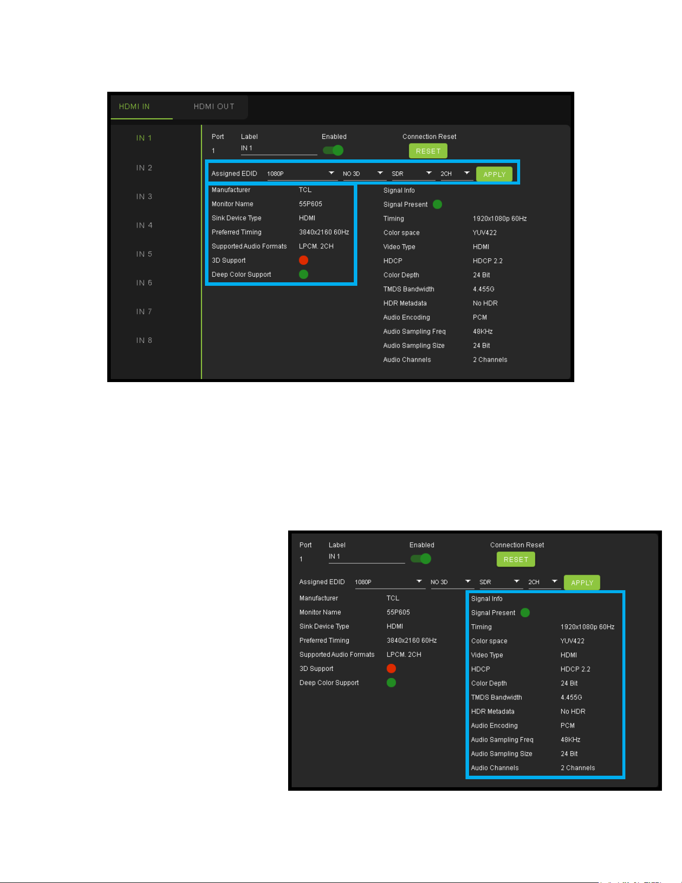
WebUI: Diagnostics - HDMI IN Cont.
On the left, you will see the current applied EDID information. In the example above, you will see a canned 1080P - No 3D - SDR
- 2CH EDID applied to IN 1. Any EDID change, once applied will display here.
Signal Info shows the connected source’s current output information. This includes
·Timing
·Color Space
·Video Type
·HDCP Version
·TMDS Bandwidth
·HDR Metadata
·Audio Sampling Frequency
·Audio Sampling Size
·Audio Channels
29
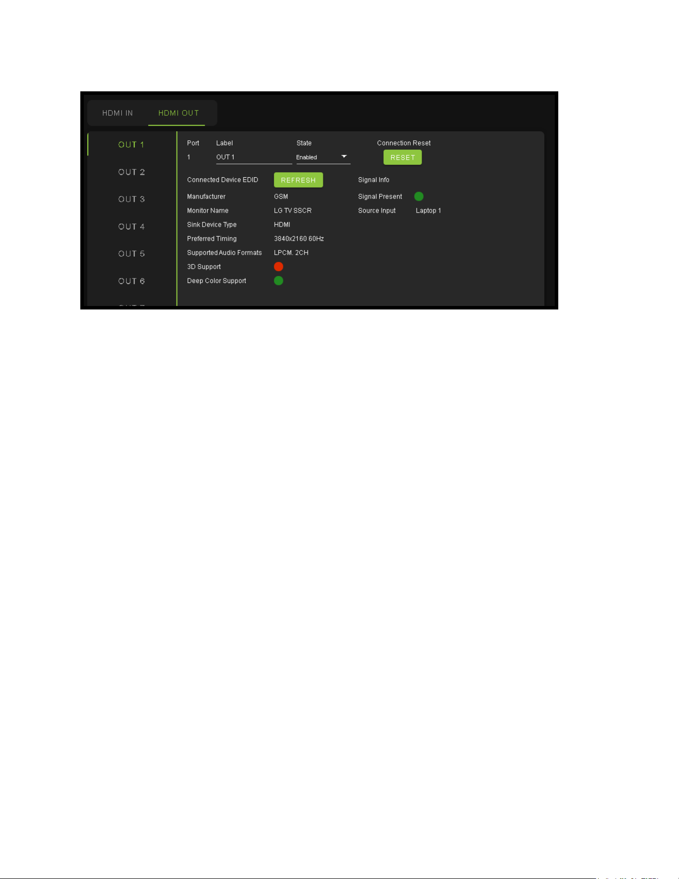
WebUI: Diagnostics - HDMI OUT
HDMI Output Label, State, and Connection Reset.
Connected Device EDID shows the connected sync’s preferred EDID information and current state.
This includes
·Manufacturer
·Monitor Name
·Sink Device Type
·Preferred Timing
·Supported Audio Formats
·3d Support
·Deep Color Support
·Signal Present
·Source Input (future update)
30
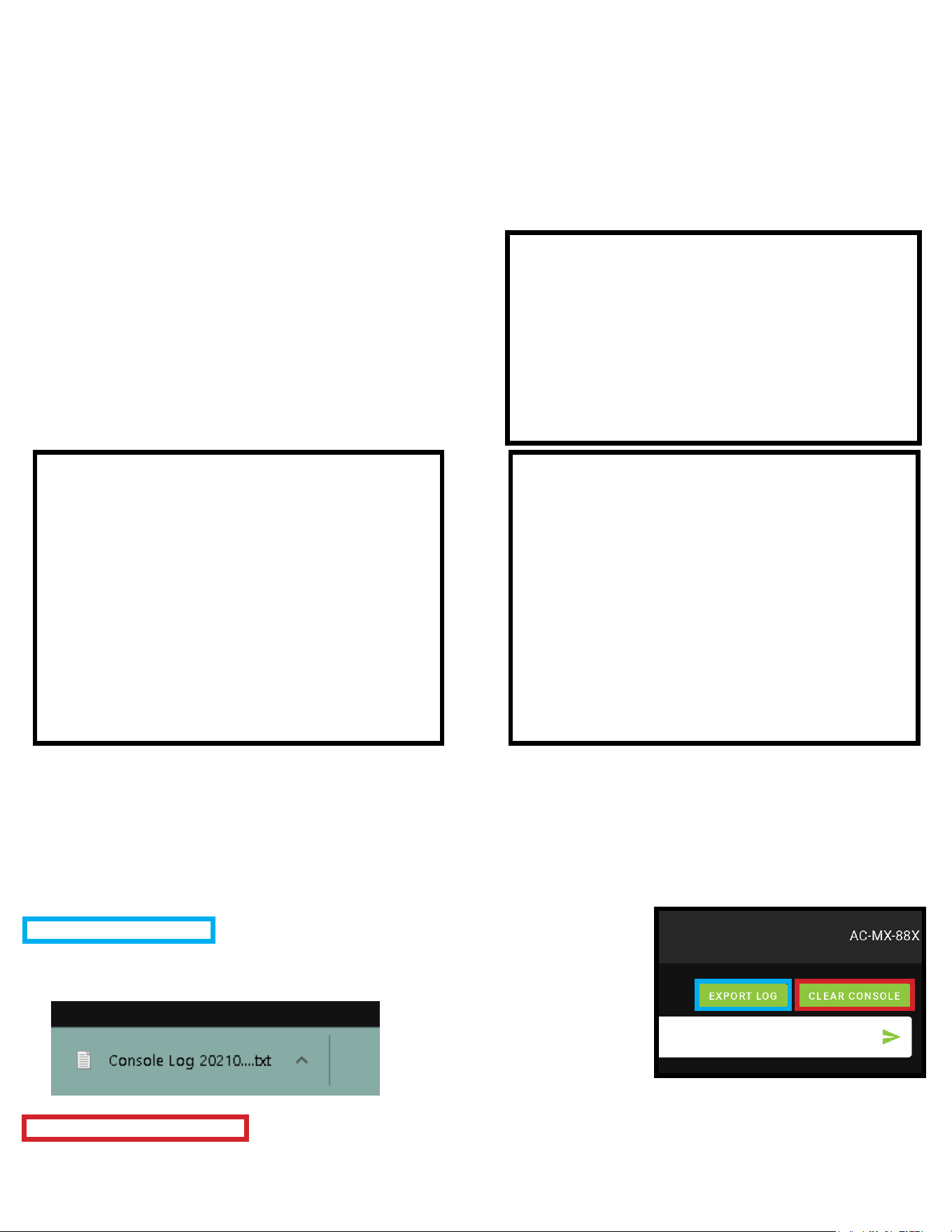
WebUI: Console
There is a built in Command Console
Using the command API (command list) you can send device specic commands or use as a live monitor
while sending commands from a control system (helpful in troubleshooting).
Example
1. Click in the white box and type
a. GET STA
Click the green arrow or hit ENTER/RETURN on your
keyboard
The the command response will show in the eld below.
CLEAR CONSOLE - Button
This button will clear the current console session.
EXPORT LOG - Button
This button will generate a text le containing the console
information in your web browsers download folder.
*NEW to NET MCU Firmware Version 1.06
Example - “GET STA”
Get status
Example - “H”
Help command
Returns all Available Commands
31
Front Panel Control - Switching
The AC-MX-88X can be switched from the front panel by rst pressing the desired OUTPUT (bottom row)
button rst, then by pressing the desired INPUT button (top row).
1. Press the OUTPUT button (1 through 4) on the bottom row that corresponds with the OUTPUT
(Display, or Sink Device) you would like to send to a source.
2. Once pressed, the front panel display will change to the SWITCH menu showing the current IN/OUT
routes. Press the corresponding OUTPUT button (top row) to set.
You can also use the arrow keys and navigate to SWITCH on the front screen display.
1. Use the left/right arrows to select the OUTPUT press the OK button (the selection will turn red).
2. With the selection now red press the desired OUTPUT button (1-4) that you want to route to that
INPUT.

32
Front Panel Control - EDID
This matrix has 29 factory dened EDID settings. It also has 3 user dened EDID memories. The user
EDID memories are independent to each input and can be set dierently. The user dened EDID can be
uploaded using the free PC Control software or RS-232. In addition, you can choose to read the EDID from
the desired output and the captured EDID will automatically store and overwrite the EDID in “USER EDID 1”
and will be applied to the selected source.
·Use the arrow keys to highlight EDID then press OK to enter the EDID management menu.
·Use the Left/Right arrow to select one of the 4 INPUTS, and press OK.
·The EDID Status will turn red, now you can use the UP/DOWN arrows to change the EDID.
·Once the desired EDID is selected, press the OK button to set.
NOTE: See page[s] 18 and 37 for full EDID list
In order to obtain Dolby Atmos, DTS:X, or other HBR Surround formats, the EDID must be copied from a capable device.

33
Front Panel Control - Audio
Once in “Matrix” mode for audio, the extracted audio routing on the AC-AXION-8 can be controlled from the
front panel.
To Control:
1. Navigate to the Audio Menu.
2. Use the arrow key to highlight “Audio Mode” and press OK to select. The eld will turn red.
3. Use up/down arrow keys to change to “Matrix”.
4. Press the OK button again to set.
5. With the Audio Mode set to Matrix, you can use the INPUT/OUTPUT Buttons to route the audio.
Press OUTPUT number rst, then the INPUT number next.
Front Panel Control - Network
This menu displays the current Network information. You can edit the following Network settings from the
front panel.
• RIP
• HIP
• MASK
• TCP/IP
• DHCP
NOTE: The MAC Address is only viewable, you can not edit.
1. Use the up/down arrow keys to highlight the setting you would like changed and press OK to select.
The eld will turn green.
2. Use up/down/left/right arrow keys to change the value.
3. Press the OK button again to set.
To change a setting:
34
IR Control: IR Remote
IR Remote Control:
When routing HDMI, the matrix can be controlled by using the IR remote
supplied When routing HDMI, the matrix can be controlled by using the IR
remote supplied with the product (battery not included, requires CR2025).
The labels on the left are the OUTPUT numbers.
The arrow buttons are for cycling through the INPUTS. Pressing the left
arrow will decrease (move to previous input) and pressing the right arrow will
increase (move to next input).
IR Window
The IR EXT. port on the back can accept an IR Receiving Eye (one included in the box).
IR Control: Extension Port

35
RS-232 and TCP/IP Control
The AC-MX-88 can be controlled with either RS-232 or TCP/IP commands. Certain switching or format
congurations can only be done using these commands. We recommend using either the MyUART (RS-232
- free) or Hercules (TCP/IP - free) apps as they are very easy to use for sending commands to the machine.
For TCP/IP control commands use Telnet Port 23.
For RS-232, use a null modem serial cable adapter and set the serial communications to: 57600,n,8,1 (baud:
57600, no parity, 8 data bits and 1 stop bit) with no handshaking.
Please add a carriage return (Enter key) after each command when using direct commands.
The unied command list (ASCII) is listed on the following pages. Text version available here, and under
the resources tab of on the products web page.

36
Command List
· Baudrate: 57600
· Checksum: None
· Bit Num: 8
· Stop Bit: 1

37
Command List Continued

38
Command List Continued

39
Extracted Audio
The extracted audio ports have three distinct operating modes. Your desired mode can be set to suite your
particular installation.
The 3 modes are:
Bind to Input ~ This is the default conguration. In this mode the audio port number corresponds to the
INPUT signal. This is ideal for systems where audio is matrixed separately in a zoned amplier.
Bind to Output ~ This conguration will automatically have the audio follow OUTPUT, so the audio from
the extracted port always matches the HDMI output. This is ideal for systems that use local AVR’s for some
of the zones.
Independent/Matrix ~ This mode allows you matrix the extracted audio outputs independent of HDMI.
In this mode a new set of commands becomes available to be able to route audio however you want. This
can be used as a separate zoned audio matrix with only using an amplier.
Setting up Extracted Audio Routing:
You can set up Extracted Audio Routing from the front panel, WebUI, Driver or by sending the following
command:
SET EXAMX MODEx -- Where {x=[0~2](0=Bind To Output,1=Bind To Input,2=Matrix}
If you set to “Matrix” you can use the following command to route the 16 extracted audio ports to any
INPUT:
SET OUTx AS INy -- Where Set Ex-Audio Output x To Input y{x=[0~4](0=ALL), y=[1~4]}
Balanced 5 pin 2Ch and Toslink Audio Port /SPDIF:
The SPDIF Toslink port supports up to 5.1 Ch Digital audio the balanced 5 pin terminal connector supports
2 Ch audio only. This means in order for these ports to function the sources must be set to 2 Ch PCM, this
unit does NOT down mix the audio (see AC-AXION-4 for down-mixing matrix). To get more than 2 Channels
you will want to use the SPDIF port.

40
Audio Output Logic and Cable Prep
You can extract audio from Toslink or balance 2CH Audio.
2CH Balanced Audio Port - Supports 2CH PCM audio only, which is ideal for 2 Channel systems and zoned
audio systems. No Down-mixing on this version, see AC-AXION-4.
Toslink Audio Port - Toslink extracted audio ports support up to 5.1 digital audio.
You can use balanced analog outputs in a balanced system, but you can also prep a cable as shown below
to convert to a traditional 2CH unbalanced (L/R) system. You can also purchase pre-made cables (AC-
CABLE-5PIN-2CH) four of these are included in the box when purchased.
AC-CABLE-5PIN-2CH

41
Troubleshooting
·Verify Power - Check that the power supply is properly connected and on an active circuit.
·Verify Connections - Check that all cables are properly connected.
·Use the System section of the WebUI to verify the matrix rmware is up to date - Page(s) 25-26
·Use the Diagnostics section of the WebUI to verify the HDMI Input/Output status and EDID settings.
Page(s) 27-29.
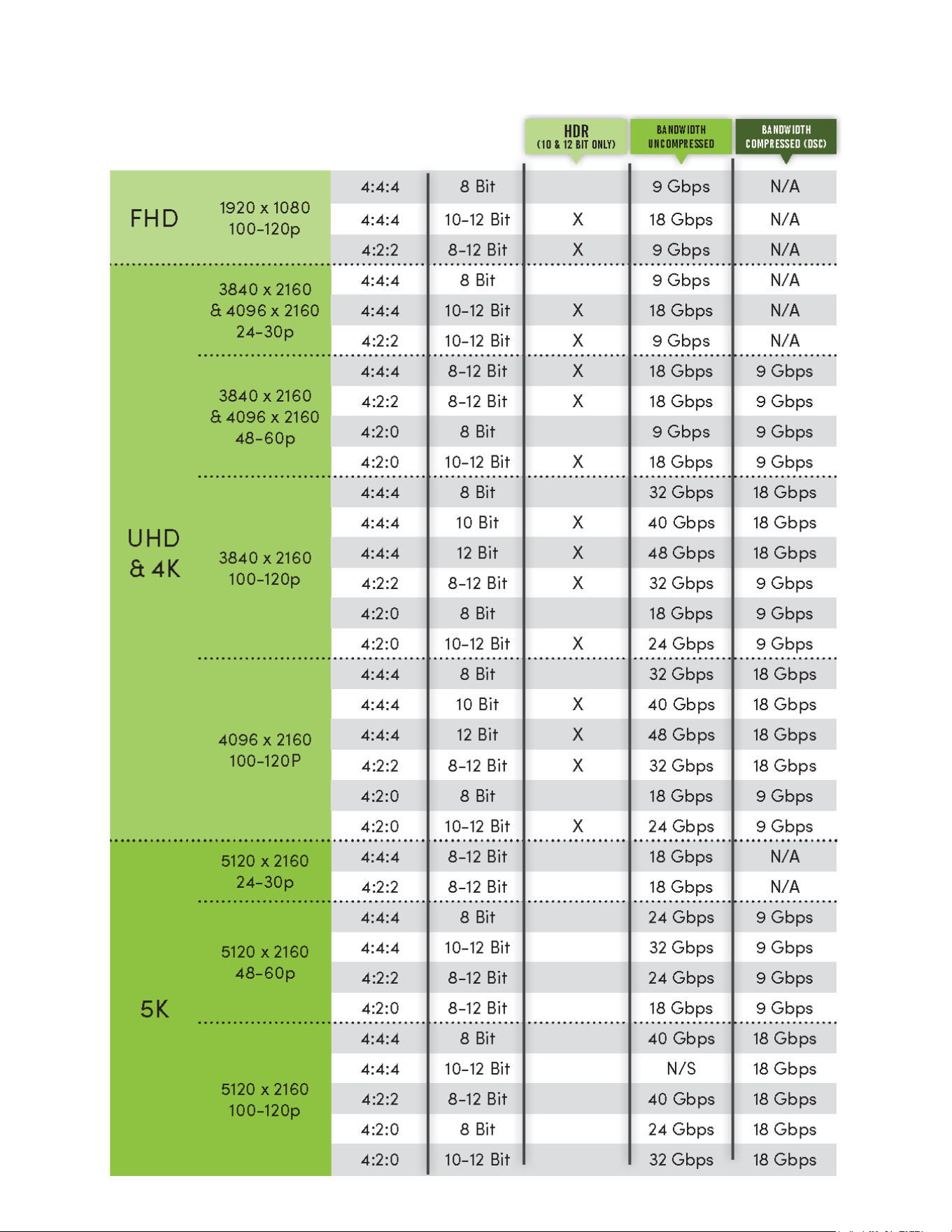
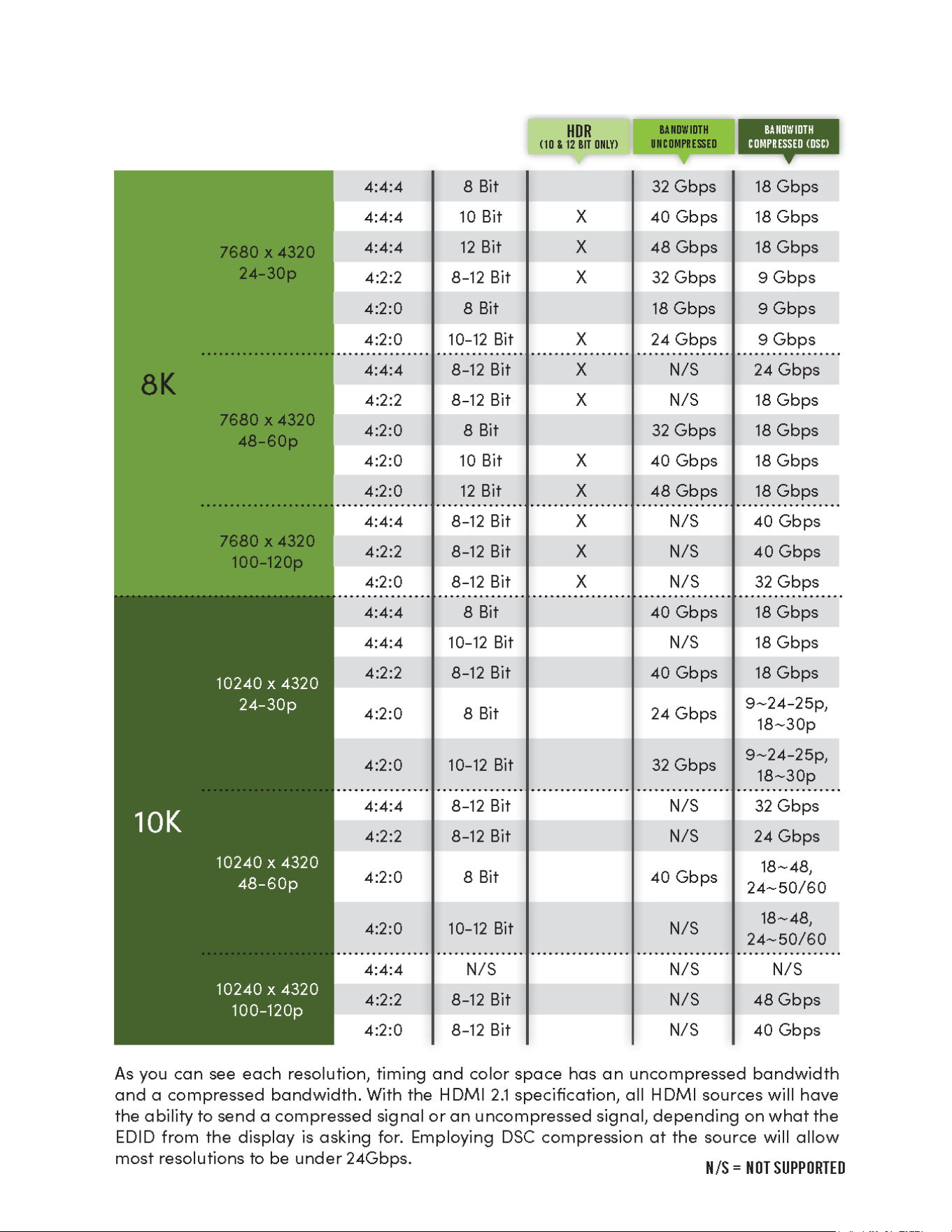
·Diagnostics page indicates everything is good but still not getting a picture, this may be a bandwidth
limitation. See Bandwidth Chart on pages 42 and 43 to verify the signal is not exceeding the
bandwidth of any of the devices in the chain.
·Still experiencing issues, contact our technical support for further assistance
1-877-886-5112
605-274-6055
42
Bandwidth Chart
43
Bandwidth Chart Continued

44
Maintenance
To ensure reliable operation of this product as well as protecting the safety of any person using or
handling this device while powered, please observe the following instructions.
·Use the power supplies provided. If an alternate supply is required, check voltage, polarity
and that it has sucient power to supply the device it is connected to.
·Do not operate these products outside the specied temperature and humidity range given in
the above specications.
·Ensure there is adequate ventilation to allow this product to operate eciently.
·Repair of the equipment should only be carried out by qualied professionals as these
products contain sensitive components that may be damaged by any mistreatment.
·Only use this product in a dry environment. Do not allow any liquids or harmful chemicals to
come into contact with these products.
·Clean this unit with a soft, dry cloth. Never use alcohol, paint thinner or benzene to clean this
unit.
Damage Requiring Service
The unit should be serviced by qualied service personnel if:
·The DC power supply cord or AC adapter has been damaged
·Objects or liquids have gotten into the unit
·The unit has been exposed to rain
·The unit does not operate normally or exhibits a marked change in performance
·The unit has been dropped or the housing damaged

45
Support
Should you experience any problems while using this product, rst, refer to the Troubleshooting section
of this manual before contacting Technical Support. When calling, the following information should be
provided:
·Product name and model number
·Product serial number
·Details of the issue and any conditions under which the issue is occurring
·Clean this unit with a soft, dry cloth. Never use alcohol, paint thinner or benzene to clean this unit.
Warranty
THE BASICS.
AVPro Edge warranties its products that are purchased from all Authorized AVPro Edge Resellers or direct purchases. Products are
guaranteed to be free from manufacturing defects and of sound physical and electronic condition.
AVPro Edge has developed a warranty that anyone can get behind. We really wanted to take all the “red tape” out of a warranty
and just make is simple. Our 10 YEAR NO BS warranty hinges on 3 elements.
1. If you are having trouble, call us. We will attempt to troubleshoot your issue over the phone.
2. If it’s broke - We’ll replace it in advance on our dime. (We’ll cover return shipping too.) Repair is an option too, but it’s
YOUR call.
3. We know you know what you are doing. We will not make you go through unnecessary steps to troubleshoot an
extender...
COVERAGE DETAILS.
AVPro Edge will replace or repair (at customer choice) the defective product. If the product is out of stock or on back order it can
either be replaced with a comparable product of equal value/feature set (if available) or repair.
Your warranty begins at receipt of product (as conrmed by shipping rm tracking). If tracking information is unavailable for any
reason, the warranty will commence 30 ARO (After Receipt of Order). The coverage continues for 10 YEARS.
RED TAPE.
AVPro Edge is not responsible for untraceable purchases or those that were made outside of an authorized channel.
If we conclude that a product or serial number has been tampered with as identied by warranty seal or physical examination the
warranty will be void. Additionally, excessive physical damage (beyond normal wear & tear) the warranty may be voided or pro-
rated based on the extent of the damage as examined by an AVPro Edge representative.
Damage caused by “acts of God” are not covered. They can include natural disasters, power surges, storms, earthquakes,
tornadoes, sink holes, typhoons, tidal waves, hurricanes, or any other uncontrollable event related to nature.

46
Damage caused by incorrect installation will not be covered. Incorrect power supply, inadequate cooling, improper cabling,
inadequate protection, static discharge are examples of this.
Products installed or sold by a third party to AVPro Edge will be serviced by the Authorized AVPro Edge Reseller.
Accessories (IR Cables, RS-232, Power Supplies, etc…) are not included in the warranty. We will make acceptable eort to source
and supply replacements for defective accessories at a discounted rate as needed.
OBTAINING AN RMA.
Dealers, Re-sellers, and Installers can request an RMA AVPro Edge Tech Support Rep or their Sales Engineer. Or you may email
[email protected] or ll out the general contact form at www.avproedge.com
End users may not request and RMA directly from AVPro Edge and will be referred back to the Dealer, Re-seller or Installer.
SHIPPING.
For USA (not including Alaska and Hawaii). Shipping is covered on advanced replacements for FedEx Ground (some expressed
exceptions may apply). Defective product return shipping is covered by AVPro Edge using an emailed return label. Item must
be returned within 30 days of receipt of replacement product, after 30 days, the customer will be billed. Other return shipping
methods will not be covered.
For International (and Alaska and Hawaii) return shipping costs will be the responsibility of the returnee. Once the unit is scanned
for return shipping AVPro Edge will ship new unit for replacement.
LEGAL STUFF.
Limitation on Liability
The maximum liability of AVPro Global Holdings LLC under this limited warranty shall not exceed the actual purchase price paid for
the product. AVPro Global Holdings LLC is not responsible for direct, special, incidental or consequential damages resulting from
any breach of warranty or condition, or under any other legal theory to the maximum extent permitted by law.
Taxes, Duties, VAT, and freight forwarding service charges are not covered or paid for by this warranty.
Obsolescence or incompatibility with newly invented technologies (after manufacture of product) is not covered by this warranty.
Obsolescence is dened as:
“Peripherals are rendered obsolete when current technology does not support product repair or re-manufacture. Obsolete
products cannot be re-manufactured because advanced technologies supersede original product manufacturer capabilities.
Because of performance, price and functionality issues, product redevelopment is not an option.”
Discontinued or out of production items will be credited at fair market value towards a current product of equal or comparable
capabilities and cost. Fair market value is determined by AVPro Edge.
Exclusive Remedy
To the maximum extent permitted by law, this limited warranty and the remedies set forth above are exclusive and in lieu of all
other warranties, remedies and conditions, whether oral or written, express or implied. To the maximum extent permitted by
law, AVPro Global Holdings LLC specically disclaims any and all implied warranties, including, without limitation, warranties of
merchantability and tness for a particular purpose. If AVPro Global Holdings LLC cannot lawfully disclaim or exclude implied
warranties under applicable law, then all implied warranties covering this product, including warranties of merchantability and
tness for a particular purpose, shall apply to this product as provided under applicable law.
This warranty supersedes all other warranties, remedies and conditions, whether oral or written, express or implied.

47

48

49
ank you for choosing AVProEdge!
Please contact us with any questions, we are happily at
your service!
AVProEdge
2222 E 52nd St N ~ Sioux Falls, SD 57104
1-877-886-5112 ~ 605-274-6055
support@avproedge�com