Part Number 7119888 / ENGLISH REV E - 6/2025
SAVE THIS MANUAL FOR FUTURE REFERENCE
USE AND CARE MANUAL
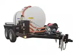
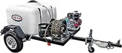
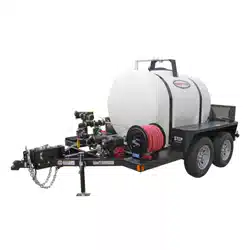
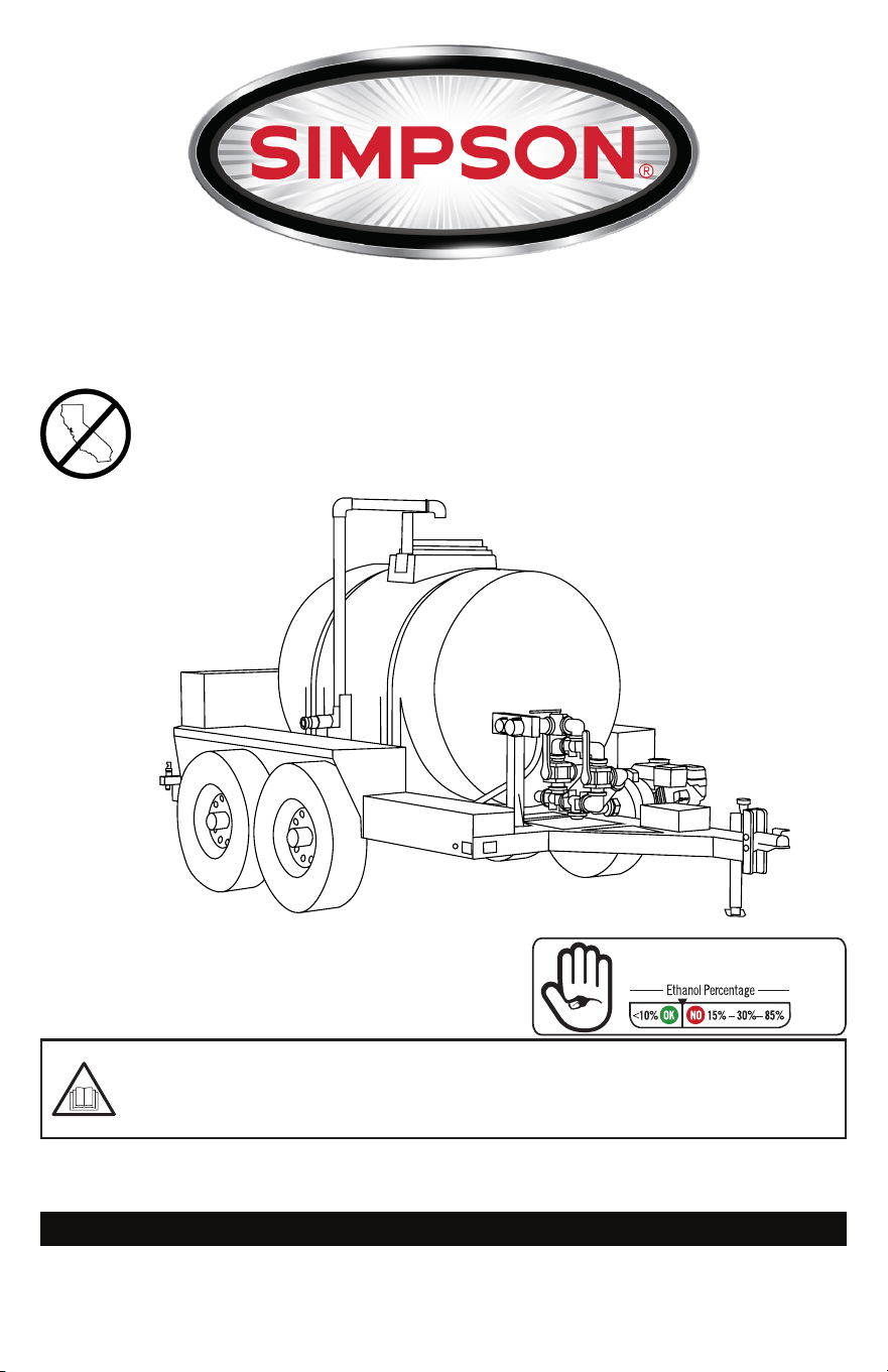
WATER TRAILER
READ THIS MANUAL CAREFULLY BEFORE OPERATION
Failure to follow the instructions and safety precautions in this manual can result
in property damage, serious injury and/or death.
NOTE: Photographs and line drawings used in this manual are for reference only and may not
represent your specic model.
If your unit is not working or if there are parts missing or broken, please DO NOT RETURN IT TO
THE PLACE OF PURCHASE. Contact our Customer Service Department by calling 1-833-362-7368
or emailing [email protected]
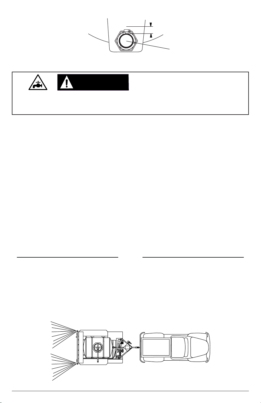
LOOK BEFORE YOU PUMP!
NOT FOR SALE IN THE
STATE OF CALIFORNIA

Page II
NOTES
THIS PAGE WAS INTENTIONALLY LEFT BLANK
Page 1
SAVE THIS MANUAL FOR FUTURE USE
Write down the model number, serial number, and purchase date of this product in the spaces
provided below then keep this manual with the purchase receipt(s) for future reference.
Keep this manual for future reference. This manual should be considered a permanent part
of the product and stay with it. This manual should be available to anyone operating the
product(s) it covers. This manual should remain with the product(s) it covers if sold to a new
owner. If the manual becomes damaged, lost, or otherwise unusable, you may download
a new copy from the product pages at www.simpsoncleaning.com or contact customer
support by calling 1-833-362-7368.
Model Number:
Serial Number:
Purchase Date:
This product and the engine exhaust can expose you to chemicals which are known to
the state of California to cause cancer, birth defects, or other reproductive harm. For
more information on California Proposition 65, go to www.P65Warnings.ca.gov.
CALIFORNIA PROPOSITION 65 WARNING
POLYCYCLIC AROMATIC HYDROCARBON WARNING
The air lter element and air box assembly may contain polycyclic aromatic hydrocarbons
(PAHs). Some PAHs may cause cancer. To avoid exposure to PAHs, wear gloves when
performing air lter maintenance.
DANGER:DANGER:
Be sure to read and completely understand both the “Utility Trailer Owner’s Manual” and
the “Mobile Pressure Cleaning Trailer / Water Trailer Additional Instructions” sheet before
towing the trailer. If you have misplaced your copy of the manual, contact our Customer
Service Department by calling 1-833-362-7368 or emailing [email protected]

Page 2
TABLE OF CONTENTS
DISCLAIMERS 5
Hazard Alert Symbols
4
Additional Instructions
4
Read this Manual Before Operating
4
4SAFETY INSTRUCTIONS
COMPONENT LOCATION 7
SUMMARY OF VALVE LOCATIONS
AND POSITIONS
8
MANIFOLD CONNECTIONS 9
DO NOT OPERATE THE PUMP WITH
THE VALVES IN THESE POSITIONS
10
VALVE POSITIONS WHEN DISCHARGING
FROM TANK
13
TRAILERING SYSTEM 20
Trailer Coupler
20
Adjusting the Trailer Coupler Height
21
Trailer Electrical System
22
Hydraulic Braking System
23
Start the Pump in Bypass
13
Using the Discharge Positions
14
Shutting Down: Valve Positions
16
VALVE POSITIONS WHEN SUCTIONING FROM A
STANDING WATER SOURCE TO THE TANK
17
PERSONAL PROTECTIVE EQUIPMENT 5
SLIP/TRIP HAZARDS 6
PRESSURE FILLING THE TANK 12

Page 3
OPERATING CHECKLIST
Location
High Altitude Operation
Operating Conditions
Checking the Engine Oil
Checking Fuel
24
24
24
24
26
27
29STARTING THE ENGINE
31
SHUTTING DOWN THE ENGINE
31
TROUBLESHOOTING
MAINTENANCE 32
Pump Maintenance
32
Exterior Pump Cleaning
32
Interior Pump Cleaning
33
Engine Maintenance
35
Plumbing Maintenance
35
Trailer Maintenance
35
ENGINE LONG-TERM STORAGE 36
Storing for Two Months or Less
36
Storing for More Than Two Months
36
WARRANTY 38
DRAINING THE SYSTEM FOR
STORAGE (WINTERIZE)
37
Draining the System
37
Page 4
CAUTION:CAUTION:
NOTICE
This manual contains important safety information and instructions. Do not operate
this product until you have read, and completely understand all safety, operation, and
maintenance instructions listed in this manual. Failure to follow the information contained
in this manual will result in property damage, injury, and/or death.
NOTE: The warnings and precautions discussed in this manual cannot cover all conditions
and situations that may occur. The operator must understand awareness and caution are
factors which cannot be built into this product and so must be exercised by the operator.
READ THIS MANUAL BEFORE OPERATING
Be sure to understand the safety symbols and denitions listed below. Each symbol
contains one of four words: DANGER, WARNING, CAUTION, NOTICE, indicating
dierent levels of hazard severity. These symbols are used throughout this manual and
are followed by information about a specic hazard, the consequences of the hazard, and
instructions on how to avoid the hazard. Failure to heed these symbols and follow the
instructions provided with them will result in property damage, injury, and/or death.
HAZARD ALERT SYMBOLS
Indicates an imminently dangerous situation, which if not
avoided, will result in property damage, serious injury, and/
or death.
Indicates a potentially hazardous situation, which if not
avoided, could result in property damage, serious injury, and/
or death.
Indicates a hazardous situation, which if not avoided, could
result in property damage and/or minor to moderate injury.
Indicates information considered important, but not directly
hazard related.
SAFETY INSTRUCTIONS
DANGER:DANGER:
WARNING:WARNING:
ADDITIONAL INSTRUCTIONS
Along with this manual, be sure to read any additional instructions provided both on and
with the product, attached equipment, accessories, and the engine powering the product.
Pay careful attention to all additional safety rules and instructions on proper startup,
operation, and shutdown procedures. Always use any recommended protective apparel
that may be needed to operate the equipment safely.
Do not operate the unit when fatigued or under the inuence of drugs and/or alcohol. Stay
alert at all times. Do not overreach or stand on an unstable surface. Do not use while
standing on a ladder. Reactive force of the spray will cause hose to kickback and could
cause the operator to slip or fall or misdirect the spray. Expect and control this reactive
force when using a spray hose. Never point hoses at or spray people and/or animals.
WARNING:WARNING:
UNSAFE PRACTICES
Page 5
Attempting to start the engine incorrectly or using the unit incorrectly can result in engine
and/or pump failure and may cause serious injury or death. To avoid these hazards, be
sure to read, understand, and follow the steps outlined in the OPERATING CHECKLIST
section of the owner’s manual before starting the engine and follow all the guidelines for
proper use of the unit.
OPERATING CHECKLIST
WARNING:WARNING:
The SIMPSON Water Trailer is designed to be used only with fresh water, gray water, and
brine. Do not pump or transport euent, black (sewage) water or any types of volatile
chemicals. Do not use hot water; use cold water only.
FLUID USAGE
WARNING:WARNING:
NOTICE
This appliance is not intended to be used by persons with reduced physical, sensory, or
mental capabilities, or lack of experience and knowledge, unless they have been given
supervision or instruction concerning use of the appliance by a person responsible for
their safety.
Children should be supervised to ensure that they do not use or play with the appliance.
DISCLAIMERS
All information in this publication was based on the latest product information
available at the time of printing. The FNA Group reserves the right to update,
change, and/or improve the product and this document at any time, without
notice and without incurring any obligation.
This manual may cover more than one machine. The pictures and gures
in the manual should be used for reference only. There may be dierences
between your product and the pictures, drawings and diagrams in this manual.
If you loan, rent or sell this machine, be sure to include all instructional materials
with the unit!
PERSONAL PROTECTIVE EQUIPMENT (PPE)
Hearing - Ear plugs or mus to protect your hearing.
Clothing - Long pants and a long-sleeved shirt to protect your legs and arms from
ying debris.
Shoes - Rubber-soled shoes that fully cover your feet to protect against debris, over
spray, and electric shock.
It is important to understand what personal protective equipment (PPE) should be
utilized when using your unit as light or unsecured objects can become hazardous
projectiles. Below is a list of PPE items that should be utilized at all times when using
the unit.
Vision - ANSI-approved Z87.1 safety glasses or goggles to protect your eyes.
Page 6
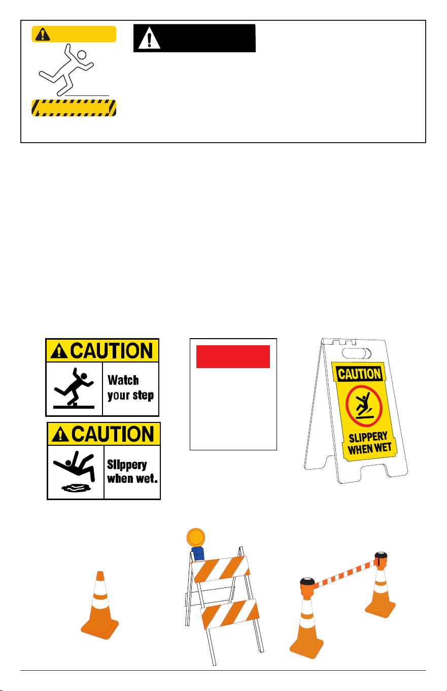
Special consideration needs to be made to the safety of not just the operator of the
unit, but also people who may be adjacent to the area being cleaned. The best way
to warn unsuspecting individuals is with signage and barriers.
Barriers can be as simple as plastic trac cones or barricades to using barrier belts
around the area being sprayed. Remember, spraying can dislodge weak or broken
pavement, turning it into projectiles that may injure others. Keeping people clear of
the area is the best way to avoid injury.
Wet pavement can be slippery to unsuspecting individuals causing injury from slips
and falls. Hoses can be trip hazards. Segregating the area and placing appropriate
signage can reduce injury.
Barrier examples
KEEP OUT
Sign examples
When spraying in public areas, signs should be posted that
indicate to stay clear of the area as spraying is being performed.
Also, signs should be posted that the surface may be slippery
and trip hazards may be present.
SLIP / TRIP HAZARDS
CAUTION:CAUTION:
Hoses may pose a tripping
hazard that can cause injuries
resulting from a fall.
CAUTION
TRIPPING HAZARD
SPRAYING
IN
PROGRESS
Page 7
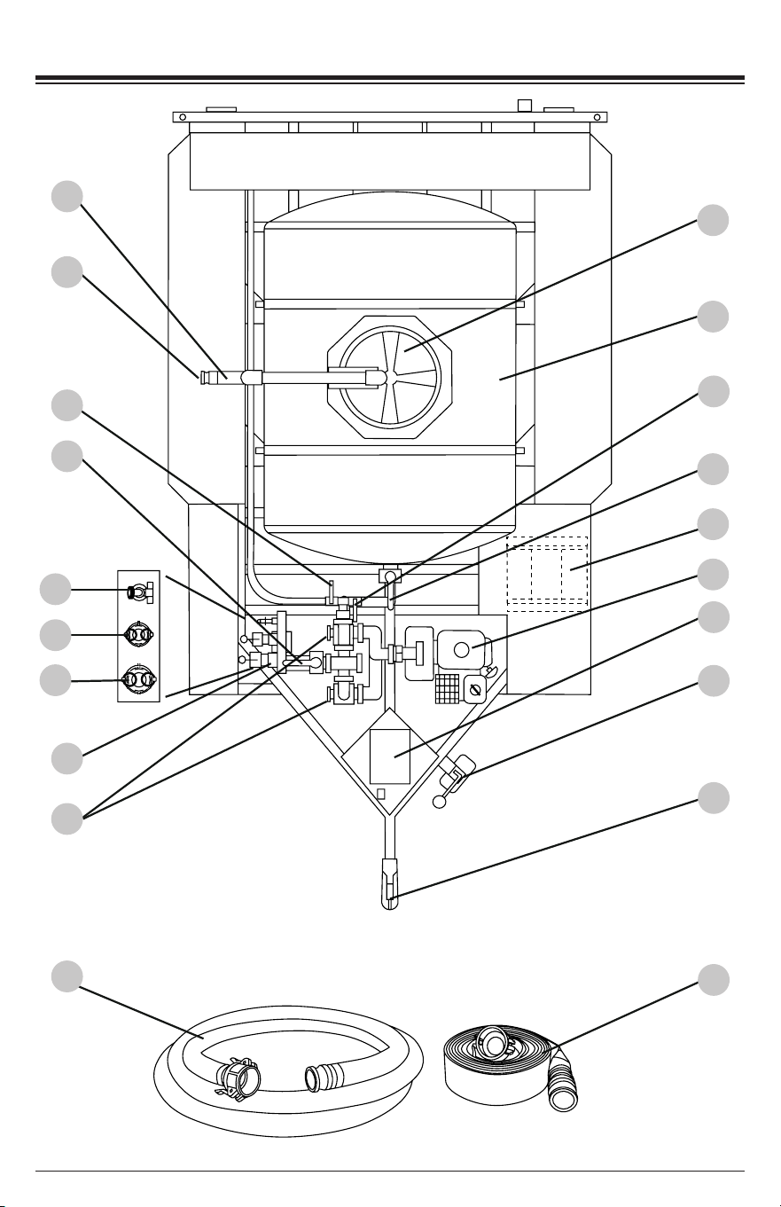
COMPONENT LOCATION
1
2
4
6
8
9
13
11
7
15
5
25
26
27
3
10
12
14
16
17
Page 8
18 19 20 21 22 23
3. SPRAY BAR valve
4. MANIFOLD valve
5. Manifold
6. FLOW valves
8. Vented tank cover
9. Tank
10.
HOSE REEL valve (optional)
11.
TANK valve and outlet (Fig. 9)
15. Trailer jack.
16. Trailer coupler
18. Red turn/brake light x 2
19. License plate holder
20. License plate light
21. Hose storage bin
22. Spray bar assembly
23. Spray nozzle (one of two)
24. Amber marker light
25. Manifold 3/4” garden HOSE BIBB
1. Pressure ll pipe
2. Pressure ll pipe 2” hose connector
7. 20ft (6.1M) Suction rated hose
17. 50ft (15.2M) lay at discharge hose
26. Manifold 1.5” HOSE connector
27. Manifold 2” HOSE connector
12. Hose reel (optional)
24
14. Poly box for electrical components
including the breakaway system
control
13.
Engine-powered pump
NOTE: Photographs and line drawings used in this manual are for reference only and may not
represent your specic model.
Page 9
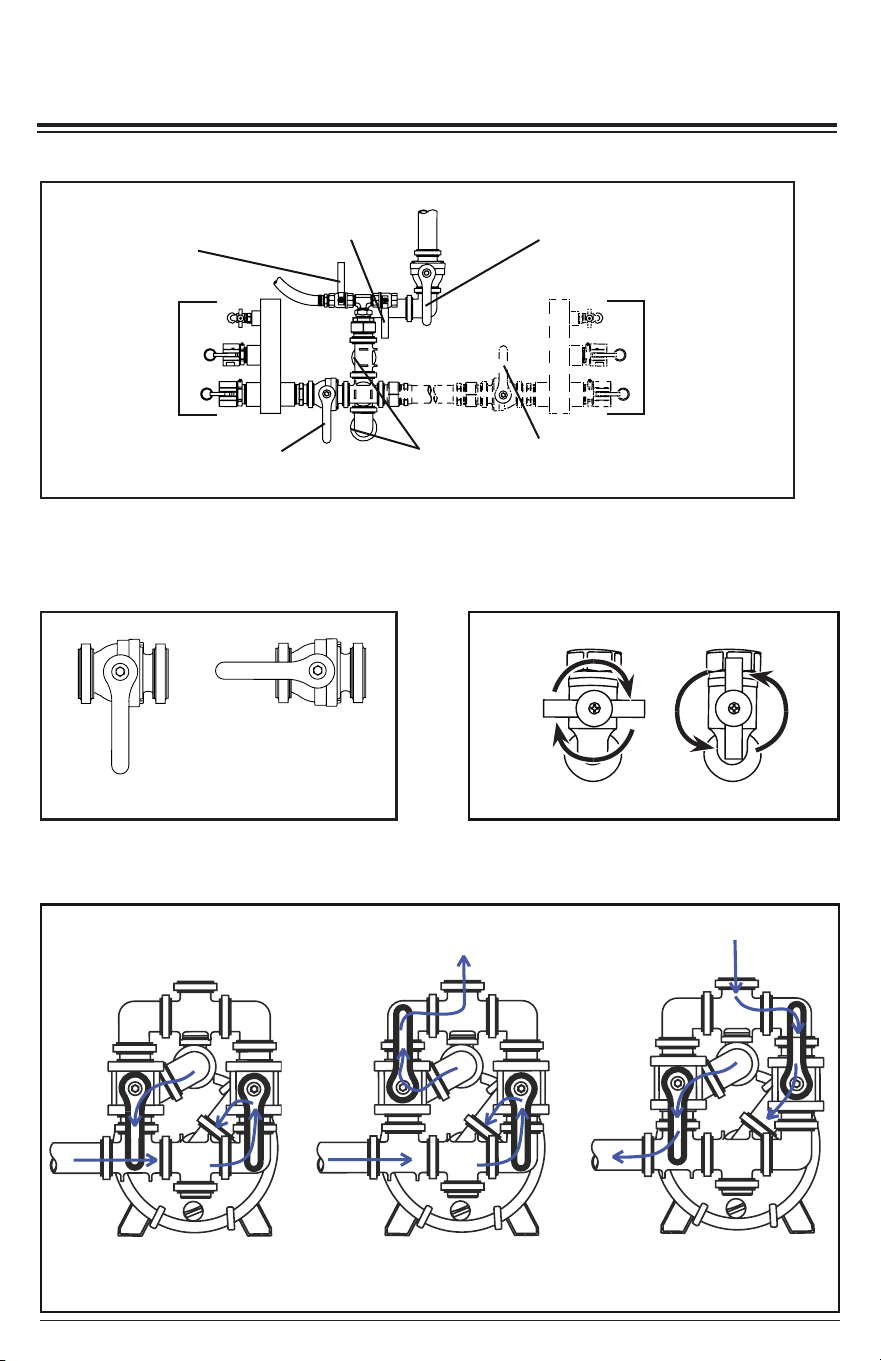
SUMMARY OF
VALVE LOCATIONS AND POSITIONS
CLOSED OPEN
Fig. 2: MANIFOLD, TANK, SPRAY
BAR, and HOSE REEL Valves
Driver’s side
MANIFOLD
(optional)
Driver’s side MANIFOLD
valve (optional)
HOSE REEL valve
(optional)
SPRAY
BAR valve
Passenger’s
side
MANIFOLD
Passenger’s side
MANIFOLD valve
TANK
valve
Fig. 1: Bird’s Eye View of Plumbing
FLOW valves
Fig. 3: HOSE BIBB
BYPASS
Input
from
Tank
DISCHARGE
Input
from
Tank
Output
SUCTION
Input
Output
to
Tank
Fig. 4: Side View of FLOW Valves
OFF
ON
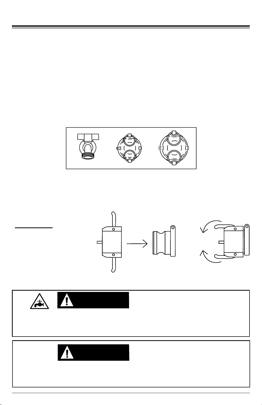
MANIFOLD CONNECTIONS
Always have the dust covers in place and locked before moving the trailer. Loose covers
may come free at highway speeds leading to injury. Make it a point each time you will be
moving the trailer to inspect the dust covers and verify they are properly locked.
DUST COVERS
WARNING:WARNING:
Page 10
The manifold allows you to discharge water from the tank out to a hose (for example,
irrigation) or to use a hose to suction water into the tank (1.5 or 2” only).
The manifold assembly contains a 1.5” HOSE connection, a 2” HOSE connection and a
standard 3/4” garden HOSE BIBB (see Fig. 5).
Fig. 5
The 1.5” and 2” HOSE connectors have cam lever dust covers (Fig. 6) that are chained
to the manifold for retention. Always have the HOSE CAMS in place and locked before
moving the trailer. Loose HOSE CAMS may come free at highway speeds, leading to
injury.
CAUTION:CAUTION:
When pumping from a standing source using the manifold, only use the 1.5” or 2” hose
connections. The 3/4” hose bibb is too restrictive and could damage the pump due to
insucient water ow.
PUMP DAMAGE
Fig. 6
HOSE CAM:
Place the cover on the hose
connector then rotate the
cams to lock the cover onto
the connector.
1.5”
HOSE
2”
HOSE
3/4”
HOSE BIBB
Page 11
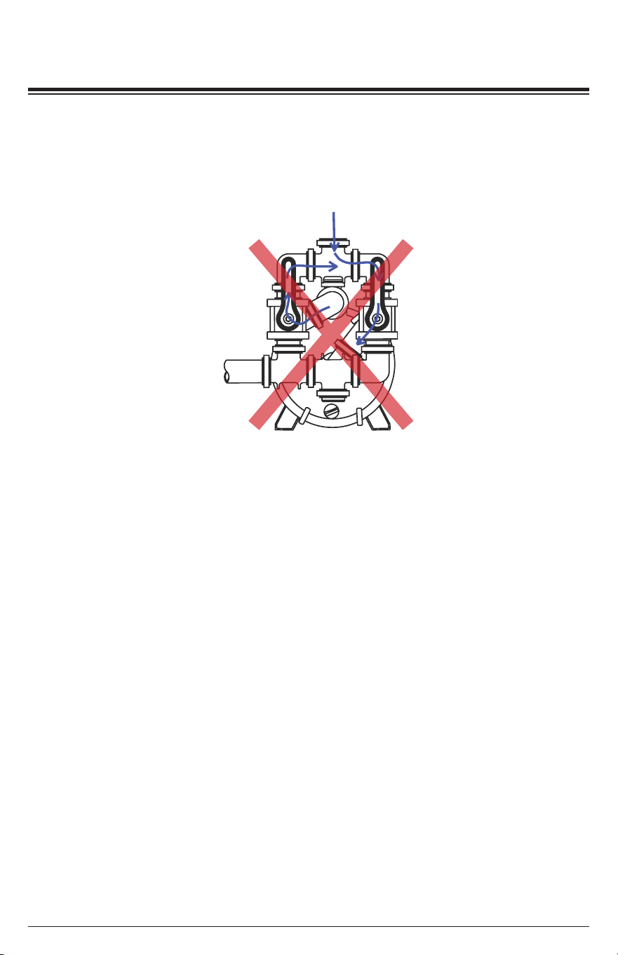
DO NOT OPERATE THE PUMP
WITH THE VALVES IN THESE POSITIONS
There are operating modes that could be harmful to your pump. It is important to never
run the pump dry as pump damage may occur. It is also important to provide proper water
movement throughout the manifold. To ensure proper pump operation, NEVER operate
the water trailer pump in these following combinations:
• Both FLOW valve handles are pointed upwards (Fig. 7).
• The FLOW valves are set to the SUCTION position (Fig. 1 and 4) and the SPRAY
BAR valve is OPEN (Fig. 1 and 2).
• The FLOW valves are set to the SUCTION position (Fig. 1 and 4) and a MANIFOLD
valve is both OPEN and DISCONNECTED (Fig. 1 and 2).
• The FLOW valves are set to the DISCHARGE position (Fig. 1 and 4) and the TANK
valve is CLOSED (Fig. 1 and 2).
• If intending to use the spray bar, the FLOW valves are set to the DISCHARGE
position (Fig. 1 and 4) and the SPRAY BAR valve is CLOSED (Fig. 1 and 2).
• If intending to use the hose reel, the FLOW valves are set to the DISCHARGE
position (Fig. 1 and 4) and the HOSE REEL valve is CLOSED (Fig. 1 and 2).
• If intending to use the MANIFOLD valve, the FLOW valves are set to the DISCHARGE
position (Fig. 1 and 4) and the MANIFOLD valve is CLOSED (Fig. 1 and 2).
• The FLOW valves are set to the BYPASS position (Fig. 1 and 4) and the TANK valve
is CLOSED (Fig. 1 and 2).
Fig. 7
PRESSURE FILLING THE TANK
CAUTION:CAUTION:
Page 12
The tank can be lled from a pressurized water source by using the 2” tank ll on the
passenger’s side of the trailer. The SIMPSON Water Trailer is designed to be used only
with fresh water, gray water, and brine. Do not pump or transport euent, black (sewage)
water or any types of volatile chemicals.
1. Remove the cover of the tank.
2. Connect a 2” hose from the pressurized water source to the ll connector.
3. Turn on the water source allowing the tank to ll to the required level.
4. Turn o the water source then disconnect the hose from the ll pipe.
5. Place the cover back onto the tank, secure.
Whenever the trailer is disconnected from the tow vehicle, the trailer should be parked
on a level surface and with the wheels chocked (not included). Trailers with non-chocked
wheels can roll when parked on non-level pavement or when accidentally bumped from
another vehicle leading to injury/death and property damage.
TRAILER MOVEMENT
PRESSURIZED
WATER
SOURCE
CAUTION:CAUTION:
Failure to properly set the valves can cause damage to the pump and the piping. Always
set the valves and verify the pump is properly primed before starting the engine.
PUMP DAMAGE
Page 13
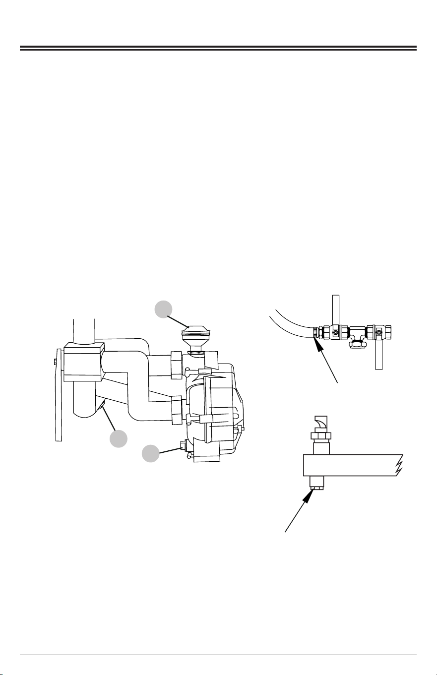
1. START THE PUMP IN BYPASS
1. Make sure the engine is OFF.
2. Move the FLOW valves to the BYPASS position (Fig. 1 and 4). This will run the
pump in a loop, allowing the engine to be started without having an output or input
hose.
3. Move the TANK valve to OPEN (Figs. 1-2).
4. Move the MANIFOLD valve, HOSE REEL valve, and SPRAY BAR valve to
CLOSED (Figs. 1-2).
WARNING:WARNING:
Attempting to start the engine incorrectly can result in engine and/or pump damage, and
may cause serious injury or death. To avoid these hazards, be sure to read, understand,
and follow the steps outlined in the OPERATING CHECKLIST section of the owner’s
manual before starting the engine, and follow all the guidelines for proper use of the
SIMPSON Water Trailer.
OPERATING CHECKLIST
NOTICE
This pump will not prime when dry. Running the pump dry without priming can damage the
pump assembly and seals. Damage caused by running dry is not covered by warranty.
To avoid damaging the seals and pump assembly, do not run the pump when it is dry
without priming.
PUMP PRIMING
VALVE POSITIONS WHEN DISCHARGING
FROM TANK
Make sure to read and understand the DO NOT OPERATE THE PUMP WITH THE
VALVES IN THESE POSITIONS section before proceeding. Make sure to follow the steps
outlined in this chapter (VALVE POSITIONS WHEN DISCHARGING FROM TANK) to
ensure the pump and all the valve handles are in the proper orientation. It is important to
read this chapter before starting, during operation, and upon shutting o the engine.
NOTICE
This pump will not prime when dry. Running the pump dry without priming can damage the
pump assembly and seals. Damage caused by running dry is not covered by warranty.
To avoid damaging the seals and pump assembly, do not run the pump when it is dry
without priming.
PUMP PRIMING
Page 14
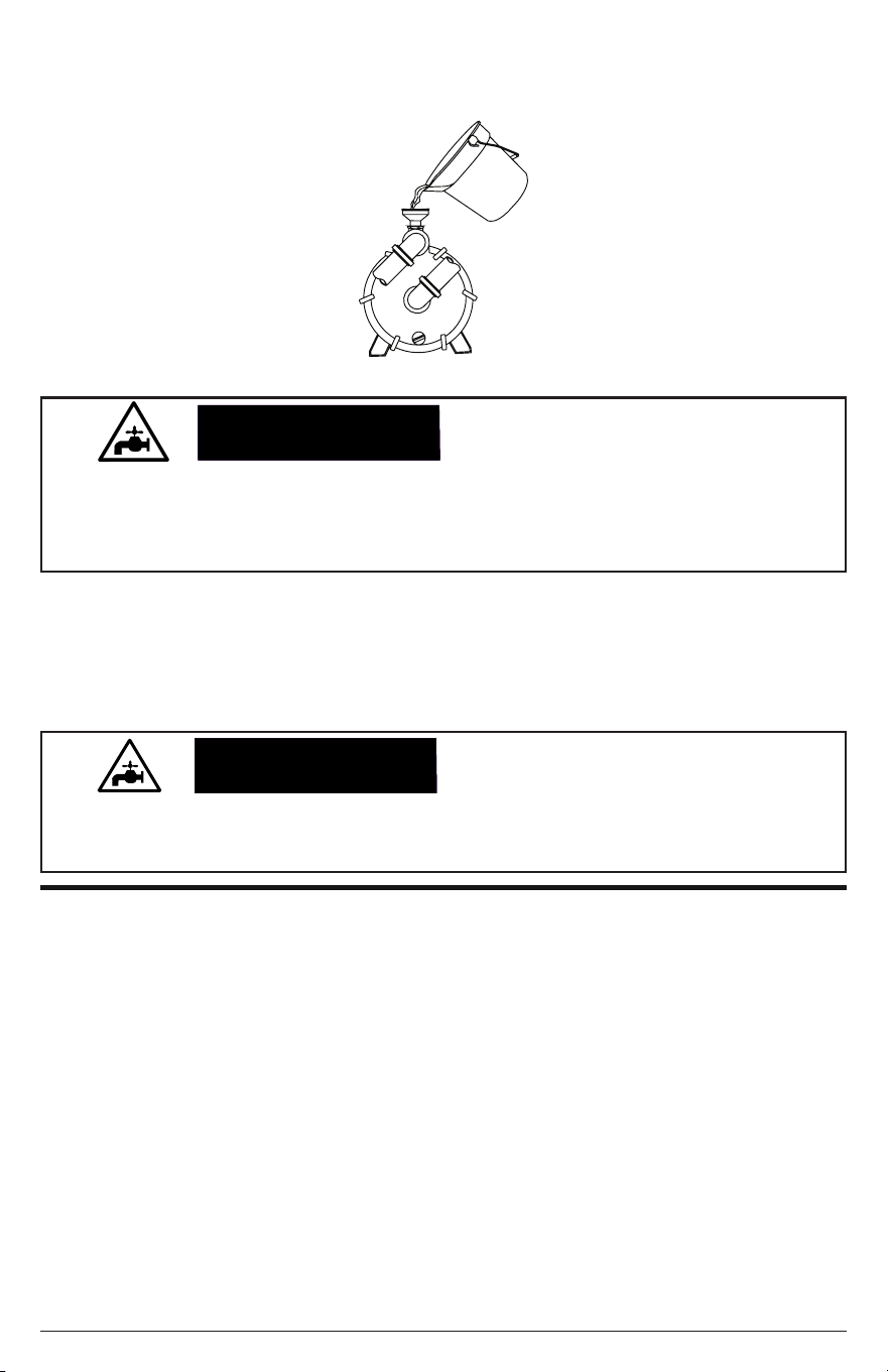
5. Ensure the pump is primed. If you start to remove the primer cover and water
begins to ow out, it is primed. If not, remove the cover and ll the pump with water
(Fig. 8). Thread the cover back onto the funnel; tighten.
6. Using the STARTING THE ENGINE instructions, start the engine of the pump.
NOTE:
Complete the steps in the OPERATING CHECKLIST section of this
manual before starting the engine. Failure to do so could cause damage to the
engine. If needed, refer to your Engine Owner’s Manual for specic starting
instructions.
Fig. 8
NOTICE
Running the engine for more than two minutes in the BYPASS position will overheat the
pump and possibly cause damage. To avoid overheating the pump, shut o the engine if
being used for longer than two minutes.
PUMP DAMAGE
2A. DISCHARGE (MANIFOLD)
The manifold connections can be used for a variety of watering uses. As talked about
in MANIFOLD CONNECTIONS, you connect a standard 3/4” garden hose, a 1.5”
hose, or a 2” hose as the output. In order to use these outputs, make sure the tank is
completely lled or has enough water for your application. Do not allow the pump to go
dry as damage may occur.
2. USING THE DISCHARGE POSITIONS
When needing to discharge water through the manifold or discharge water through
the spray bar, follow the appropriate subsection 2A, 2B, or 2C. After following the
appropriate subsection, you may switch to a dierent subsection or move to the nal
step, SHUTTING DOWN: VALVE POSITIONS. It is important to always start the pump
in bypass according to the previous section (START THE PUMP IN BYPASS) before
proceeding to this section.
Page 15
CAUTION:CAUTION:
Never allow the tank water level to fall below a level of one inch above the outlet pipe of
the tank (Fig. 9). If the tank fully drains, pump damage may occur from lack of water and
you will only be able to rell the tank from a pressurized water source.
PUMP DAMAGE
1. Follow all steps outlined in START THE PUMP IN BYPASS before proceeding.
2. Connect a hose to the appropriate manifold connection (1.5”, 2” or 3/4” garden
hose)(Fig. 5). If using a 3/4” garden hose, rotate the HOSE BIBB handle
counter-clockwise to ON (Fig. 3).
3. Move the MANIFOLD valve to OPEN (Figs. 1-2).
4. Slowly move the FLOW valves to the DISCHARGE position (Fig. 1 and 4).
5. Use the output until your application is completed or you have met the minimum
allowed amount of water in the tank. DO NOT allow the tank to pump dry.
6. Slowly move the FLOW valves to the BYPASS position (Fig. 1 and 4).
7. Move the MANIFOLD valve to CLOSED (Figs. 1-2).
8. Disconnect the hose. Place the HOSE CAM on the hose connection and lock
into place (Fig. 6), -or- rotate the HOSE BIBB handle clockwise to OFF (Fig. 3).
9. Follow subsections 2A, 2B, or 2C as needed, or proceed to the SHUTTING
DOWN section.
1” min.
TANK OUTLET PIPE
Fig. 9
2B. DISCHARGE (SPRAY BAR)
The spray bar allows you to water down areas for dust reduction as well as washing
the pavement of loose dirt and debris. In order to use the spray bar, make sure the tank
is fully lled or has enough water for your application. Do not allow the pump to go dry
as damage may occur.
OR
Page 16
CAUTION:CAUTION:
Never allow the tank water level to fall below a level of one inch above the outlet pipe of
the tank (Fig. 9). If the tank fully drains, pump damage may occur from lack of water and
you will only be able to rell the tank from a pressurized water source.
PUMP DAMAGE
1. Follow all steps outlined in START THE PUMP IN BYPASS before proceeding.
2. Move the SPRAY BAR valve to OPEN (Figs. 1-2).
3. Slowly move the FLOW valves to the DISCHARGE position (Fig. 1 and 4).
4. Use the output until your application is completed or you have met the minimum
allowed amount of water in the tank. DO NOT allow the tank to pump dry.
5. Slowly move the FLOW valves to the BYPASS position (Fig. 1 and 4).
6. Move the SPRAY BAR valve to CLOSED (Figs. 1-2)
7. Follow subsections 2A, 2B, or 2C as needed, or proceed to the SHUTTING
DOWN section.
OR
2C. DISCHARGE (HOSE REEL) (if equipped)
The hose reel is an optional accessory that would allow you to use a hose that is
mounted on the driver’s side of the trailer. In order to use the hose reel, make sure the
tank is fully lled or has enough water for your application. Do not allow the pump to
go dry as damage may occur.
CAUTION:CAUTION:
Never allow the tank water level to fall below a level of one inch above the outlet pipe of
the tank (Fig. 7). If the tank fully drains, pump damage may occur from lack of water and
you will only be able to rell the tank from a pressurized water source.
PUMP DAMAGE
1. Follow all steps outlined in START THE PUMP IN BYPASS before proceeding.
2. Move the HOSE REEL valve to OPEN (Figs. 1-2).
3. Slowly move the FLOW valves to the DISCHARGE position (Fig. 1 and 4).
4. Use the output until your application is completed or you have met the minimum
allowed amount of water in the tank. DO NOT allow the tank to pump dry.
5. Slowly move the FLOW valves to the BYPASS position (Fig. 1 and 4).
6. Move the HOSE REEL valve to CLOSED (Figs. 1-2).
7. Follow subsections 2A, 2B, or 2C as needed, or proceed to the SHUTTING
DOWN section.
3. SHUTTING DOWN
1. Shut o the engine by using the SHUTTING DOWN THE ENGINE instructions.
2. Move the TANK valve to CLOSED (Figs. 1-2).
Page 17
WARNING:WARNING:
Attempting to start the engine incorrectly can result in engine and/or pump damage, and
may cause serious injury or death. To avoid these hazards, be sure to read, understand,
and follow the steps outlined in the OPERATING CHECKLIST section of the owner’s
manual before starting the engine, and follow all the guidelines for proper use of the
SIMPSON Water Trailer.
OPERATING CHECKLIST
NOTICE
This pump will not prime when dry. Running the pump dry without priming can damage the
pump assembly and seals. Damage caused by running dry is not covered by warranty.
To avoid damaging the seals and pump assembly, do not run the pump when it is dry
without priming.
PUMP PRIMING
VALVE POSITIONS WHEN SUCTIONING FROM
A STANDING WATER SOURCE TO THE TANK
Make sure to read and understand the DO NOT OPERATE THE PUMP WITH THE
VALVES IN THESE POSITIONS section before proceeding. Make sure to follow the
steps outlined in this chapter (VALVE POSITIONS WHEN SUCTIONING FROM A
STANDING WATER SOURCE TO THE TANK) to ensure the pump and all the valve
handles are in the proper orientation. It is important to read this chapter before starting,
during operation, and upon shutting o the engine.
Whenever the trailer is disconnected from the tow vehicle, the trailer should be parked on
a level surface with the wheels chocked (not included). Trailers with non-chocked wheels
can roll when parked on non-level pavement or when accidentally bumped from another
vehicle leading to injury/death and property damage.
TRAILER MOVEMENT
CAUTION:CAUTION:
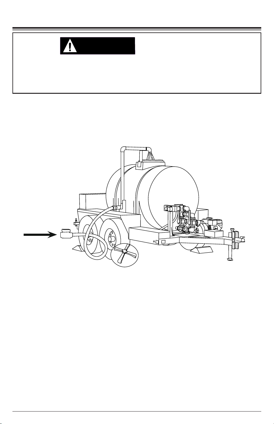
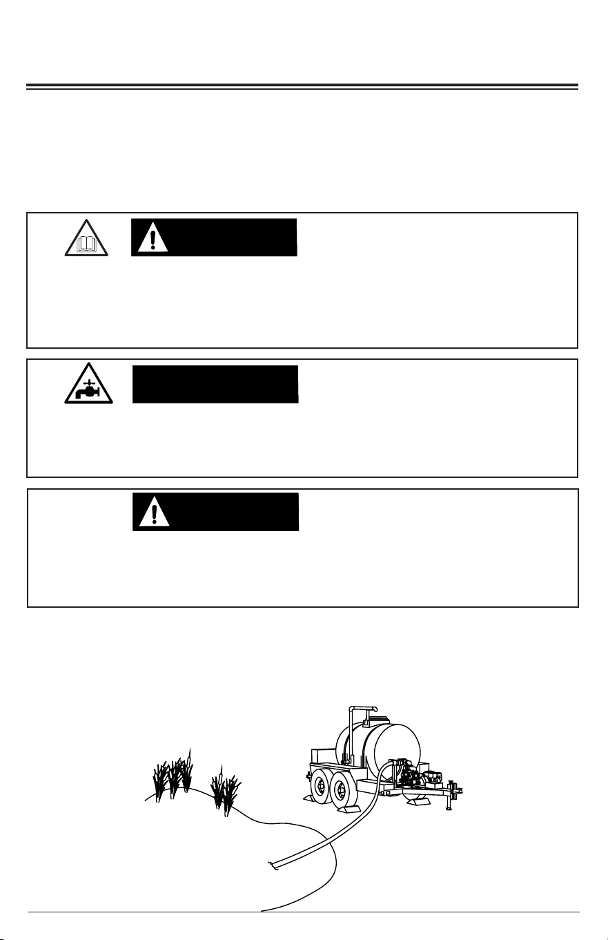
Besides lling the tank from a pressurized sources of water, you also have the ability to
ll the tank from a standing source of water such as a lake, stream or pond (Fig. 26). In
order to do this, you will need to use the 2” rigid suction hose and the on-board pump.
We recommend using a strainer / lter (not included) on the suction hose.
Fig. 10
Page 18
1. Make sure the engine is OFF.
2. Make sure the SPRAY BAR valve and HOSE REEL valve are in the CLOSED
position (Figs. 1-2).
3. Make sure the TANK valve and MANIFOLD valve are in the OPEN position (Figs.
1-2).
4. Move the FLOW valves to the SUCTION position (Fig. 1-4).
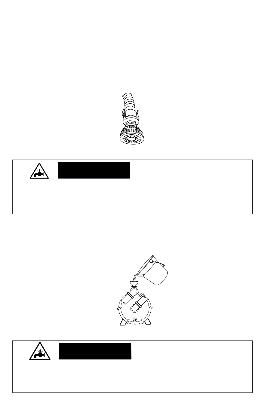
5. Place a lter / strainer (not included) onto the end of the rigid suction hose (Fig.
11), before placing the hose into the water. NOTE: The total lift from the lter /
strainer to the level of the manifold must not exceed 25 feet (7.6 meters).
Fig. 11
NOTICE
We recommended having a lter (not included) on the end of the suction hose. Not using
a lter can introduce debris into the pump and the tank that may cause damage. Always
place the lter at a depth where air cannot be introduced into the system, but do not allow
it to sit on the muddy bottom of the source.
PUMP DAMAGE
6. Connect the other end of the hose to the 2” HOSE connection (Fig. 5). Make
sure the 3/4” HOSE BIBB is OFF (Fig. 3 and 5) and the 1.5” HOSE connection
is CLOSED (Fig. 5).
7. Remove the cover and ll the pump with water (Fig. 12). Thread the cover back
onto the funnel; tighten.
Fig. 12
NOTICE
This pump will not prime when dry. Running the pump dry without priming can damage the
pump assembly and seals. Damage caused by running dry is not covered by warranty.
To avoid damaging the seals and pump assembly, do not run the pump when it is dry
without priming.
PUMP PRIMING

Page 19
8. Using the STARTING THE ENGINE instructions, start the engine of the pump. If
air begins to discharge, immediately shut o the engine by using the SHUTTING
DOWN THE ENGINE instructions.
9. Repeat steps 6-7 until only water is being discharged into the tank.
10. Fill the tank.
11. Once the tank is lled, shut o the engine by using the SHUTTING DOWN THE
ENGINE instructions.
12. Move the TANK valve and MANIFOLD valve to CLOSED (Figs. 1-2).
13. Disconnect the hose. Place the HOSE CAM on the hose connection; lock into
place (Fig. 6).
Page 20
TRAILERING SYSTEM
The trailer coupler of the SIMPSON Water Trailer is adjustable in height. It is important
to keep the trailer as level as possible with the tow vehicle. This is accomplished by
raising or lowering the coupler within the channel.
Whenever the trailer is disconnected from the tow vehicle, the trailer should be parked
on a level surface and with the wheels chocked (not included). Trailers with non-chocked
wheels can roll when parked on non-level pavement or when accidentally bumped from
another vehicle leading to injury/death and property damage.
TRAILER MOVEMENT
CAUTION:CAUTION:
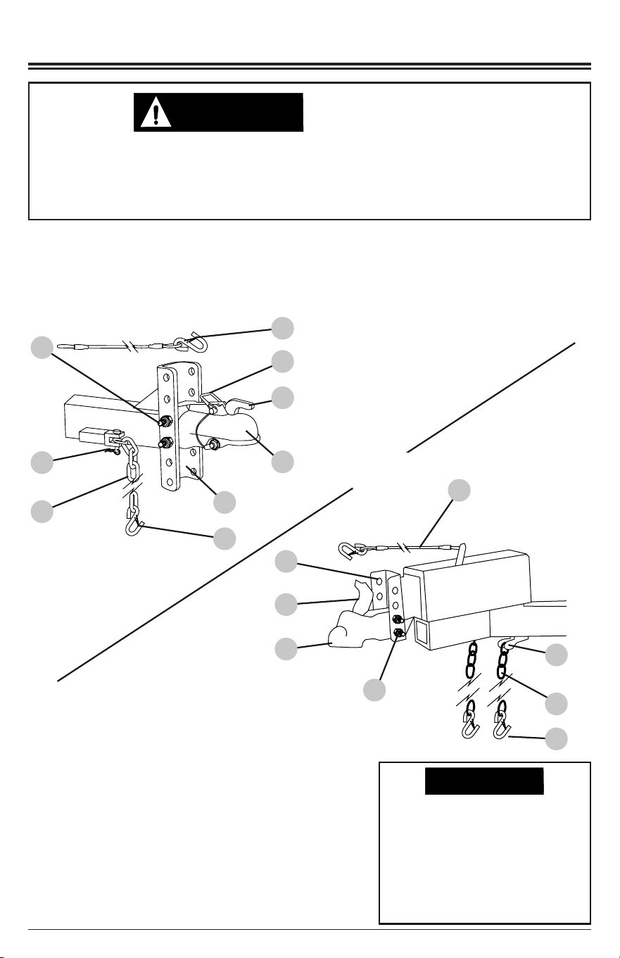
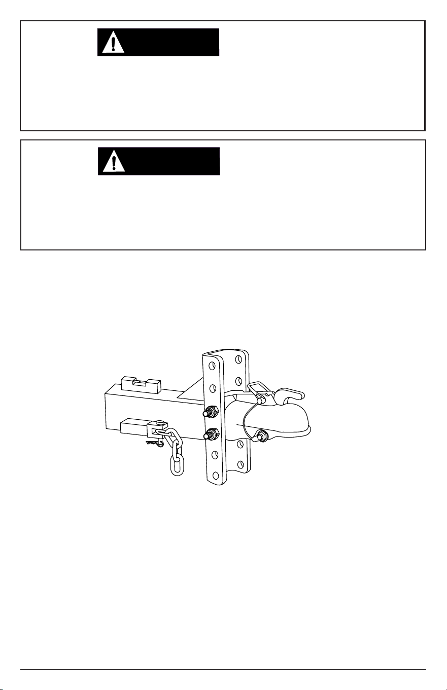
TRAILER COUPLER
NOTICE
When the trailer was ordered, you
should have picked the coupler
that matched your hitch. If you did
not specify a coupler or did not
receive one, please contact our
Customer Service Department by
calling 1-833-362-7368 or emailing
1. Coupler retaining bolt and nylon-insert locknut
2. Safety chain retaining hair pin -or- cotter pin
Safety chain assembly
4. Safety pin and lanyard
5. Latch
6. Coupler
7. Coupler channel
8. Snap hook
3.
9. Brake breakaway cable assembly
1
2
3
4
5
6
7
8
OR
2
3
5
6
7
9
Electric braking system
Hydraulic braking system
9
8
1
Page 21
Improper front / rear load distribution can lead to poor trailer sway stability or poor tow
vehicle handling. The water trailer has been designed to have the proper tongue weight
regardless of the tank being empty or full. Adding items or storing items in or on the
trailer may exceed GVWR of the axles and GTW which will change the tongue weight
distribution and cause an unsafe traveling condition. DO NOT modify or add to the trailer.
LOAD DISTRIBUTION
WARNING:WARNING:
ADJUSTING THE TRAILER COUPLE HEIGHT
1. With the trailer on level pavement and the tank empty, connect the trailer to the tow
vehicle; raise the jack.
2. Place a spirit level on the tongue behind the coupler channel (Fig. 13).
Fig. 13
Spirit level
3. The trailer should be as level as possible with the tow vehicle. If it is not, go to step
4.
4. Lower the jack to allow the tow vehicle to be moved away from the trailer.
5. Using two open end wrenches, loosen the coupler retaining bolts. Remove the nuts.
6. If the spirit level bubble was toward the vehicle (Fig. 14), the coupler is set too low.
If the bubble was toward the trailer, the coupler is set too high.
7. While holding the coupler with one hand, remove the bolts being careful not to allow
the coupler to fall to the ground.
8. Raise or lower the coupler as required to level the trailer to the tow vehicle.
The use of a hitch with a load rating less than the load rating of the trailer can result in
loss of control and may lead to death or injury. Using a tow vehicle with a towing capacity
lower than the load rating of the trailer can result in loss of control and may result in
injury or death. Be sure your hitch and tow vehicle are rated for the Gross Vehicle Weight
Rating (GVWR) of your trailer.
MATCHING TRAILER
AND HITCH
WARNING:WARNING:
Page 22
Fig. 14
Water trailer
Tow vehicle
Level
Coupler set low
Coupler set high
13. Using open end wrenches, tighten the nuts.
14. If the trailer was not level in Step 12, repeats Steps 4 through 12 until it is. Once
the level as been made as close as possible, tighten the nuts as outlined in Step 13.
9. Insert the bolts then hand thread the nuts until snug. Do not fully tighten.
10. Once again connect the tow vehicle and rise the jack.
11. Using the spirit level, check for level by placing it on the tongue.
12. If the trailer is now level to the tow vehicle, lower the jack to release pressure o
of the coupler.
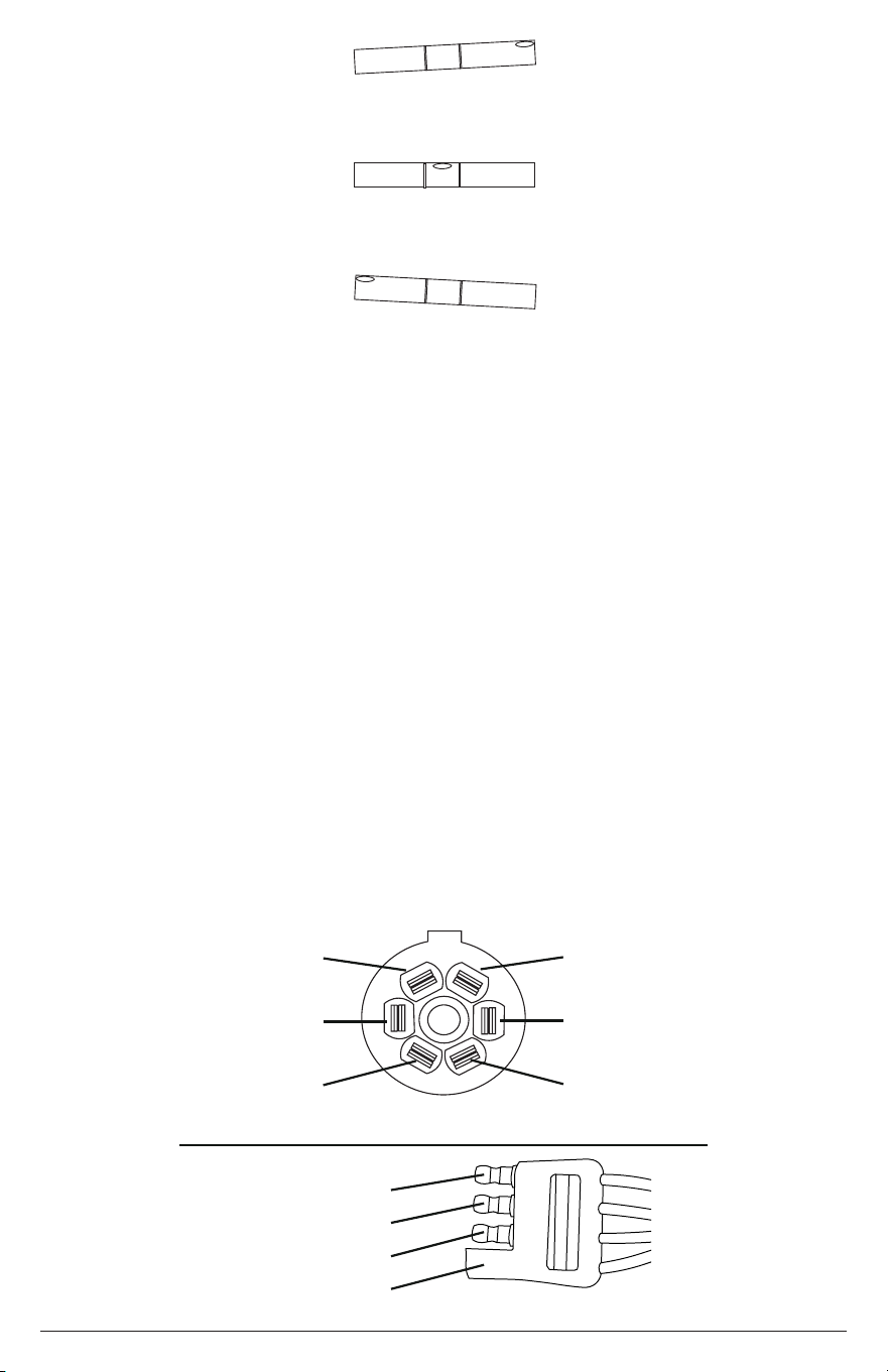
TRAILER ELECTRICAL SYSTEM
The SIMPSON Water Trailer is equipped with an electrical braking system as well as
an emergency break-away braking system. The tow vehicle must be equipped with
the appropriate receptacle for proper operation. If equipped with electric brakes, a
seven pin trailer receptacle must be wired to the SAE J2863 standard (Fig. 15). If
equipped with hydraulic brakes, a 4-way at trailer socket must be wired to the 4-way
at trailer connector (Fig. 16).
Fig. 15
Tail / running lights
(Brown)
Left turn / stop lights
(Yellow)
Ground
(White)
Aux 12 volt charging
(Red / Black)
Right turn / stop lights
(Green)
Trailer brakes
(Blue)
Ground (White)
Tail / Running Lights (Brown)
Left Turn / Stop (Yellow)
Right Turn / Stop (Green)
Fig. 16
Page 23
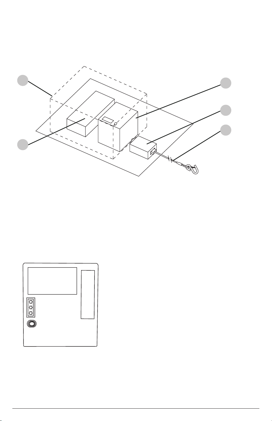
1. Poly box.
2. Wiring harness junction box.
3. Break-away controller and battery.
4. Break-away switch.
5. Break-away cable.
Fig. 17
FULL
LOW
CHARGE
TEST
Fig. 18
To test the battery, press the TEST button on the
controller housing. A green LED indicates the battery is
fully charged. A red LED indicates the battery must be
charged before the trailer is used. A steady yellow LED
indicates the trailer is connected to the tow vehicle and
the battery is being charged.
The battery should be fully charged before each use of
the trailer. NOTE: A discharged or low battery will not
operated the brakes in a break-away situation.
When trailering, you must secure the break-away cable
to the tow vehicle for the system to operate correctly in
the situation of a break-away trailer.
1
2
3
4
5
HYDRAULIC BRAKING SYSTEM (optional)
Please refer to DEMCO manual BH20022 for important safety, maintenance and
usage instructions.
The controls and battery for the break-away braking system are located within the
poly box (Fig. 17) behind the trailer tongue. The battery is charged by the tow vehicle
but should be checked periodically and after long-term storage of the trailer. The
charge status of the battery can be determined by pushing the test button (Fig. 18).
Page 24
WARNING:WARNING:
NOTICE
OPERATING CHECKLIST
Location
Engine exhaust contains carbon monoxide, an odorless, colorless, poisonous gas.
Running an engine indoors will kill you in minutes. Never use this product inside a garage
or any other kind of enclosure even if doors and windows are open. Run engine outside
at least 20 feet (6 meters) away from windows, doors, and vents. Carefully consider wind
direction and air currents when using this product outside to avoid breathing in engine
exhaust. Always use a carbon monoxide detector in any occupied buildings near the
running engine.
TOXIC FUMES
Being that this is a trailer based device, it is understood that the trailer could be
used in many dierent locations. Never operate the gasoline powered pump inside
any structure or close to any structure. Fumes can easily enter the structure causing
carbon monoxide poisoning.
High Altitude Operation
This engine will have proper engine performance and emission control when it is
operated at or below an altitude of 5000 feet (1524 meters). This engine requires a high-
altitude carburetor kit to ensure proper engine performance and emission control when
operated at altitudes above 5000 feet (1524 meters). Operating the machine with the
wrong engine conguration above 5000 feet (1524 meters) may increase its emissions,
decrease fuel eciency, and hurt performance. To obtain a high altitude carburetor kit,
contact your nearest authorized service center.
Operating the engine with a high-altitude carburetor jet kit at an altitude below 5000 feet
(1524 meters) will cause the engine to run too hot. Overheating the engine could result
in serious engine damage. To avoid this hazard, make sure the correct carburetor kit is
installed and the air/fuel mixture is set correctly for your altitude.
ALTITUDE
Operating Conditions
Before each use, check for loose or damaged parts, leaks, and/or any other condition
that may aect proper operation. Repair or replace all damaged and/or defective parts
with authorized parts immediately. Do not operate the machine with missing, broken,
or unauthorized parts. Always keep all safety guards in place and in proper working
order. For safety reasons, the manufacturer recommends all maintenance and repairs
be performed by an authorized service center.
Before starting the engine, remove any excessive dirt and debris from cooling vents,
exhaust, and starter recoil areas. If you have questions about the proper use of your
pump, please contact customer support at 1-833-362-7368 or [email protected].
Page 25
Spray directed at electrical receptacles or switches, or objects connected to an electrical
circuit, could result in a fatal electrical shock. Direct spray away from electric receptacles,
switches and equipment. Never clean any electrically operated device, even when
disconnected, unless it clearly states in its manual that such cleaning is approved.
ELECTRICAL SHOCK
DANGER:DANGER:
Operating the engine in an explosive environment could result in a re. Operate and
fuel equipment in well-ventilated areas free from obstructions. Equip areas with re
extinguisher suitable for gasoline res.
RISK OF EXPLOSION
OR FIRE
DANGER:DANGER:
WARNING:WARNING:
Failure to inspect this product before use could create a hazardous situation resulting in
product damage, serious injury, and/or death. To avoid these hazards, inspect the trailer
before each use. Check for loose or damaged parts, signs of oil or fuel leaks, missing
guards, plugged cooling vents, or any other condition that may aect proper operation.
Repair or replace all damaged or defective parts with authorized parts and keep all safety
guards in place and in proper working order before using the trailer.
INSPECT BEFORE
OPERATING
CAUTION:CAUTION:
A running engine produces heat. The surfaces of the engine, other related components,
and engine exhaust gas can get hot enough to cause moderate burns or ignite materials
on contact (such as siding, plastic, rubber, vinyl, or hoses). To avoid burns, do not touch
engine surfaces or exhaust gases while operating and allow engine to cool completely
before moving, touching, or performing any maintenance. To avoid a re, keep all
ammable materials at least ve feet away from all sides of the engine. Do not store extra
fuel on the trailer. Never cover the engine during operation or directly after being used.
HOT SURFACES
WARNING:WARNING:
This product has many parts that move at high speeds. Moving parts can cause crushing
injuries, broken bones, severe lacerations, and/or traumatic amputations. To prevent
injury, never place ngers, hands, feet, or other body parts near running engine. Never
operate product with covers, shrouds, or other guards removed. Do not wear loose-tting
clothing, dangling drawstrings, or any other hanging items that could become entangled
in moving parts while operating. Tie up long hair and remove jewelry before operating.
MOVING PARTS
WARNING:WARNING:
Do not allow children or untrained adults to operate or play with the appliance as they
can be seriously injured or killed. Anyone operating the appliance should receive proper
instructions, understand safe operation, and thoroughly read the owner’s manual before
operating this product. Keep children and pets away from the appliance while it is in
operation. Always turn o the engine before leaving the area.
CHILDREN AND
UNTRAINED ADULTS
Page 26
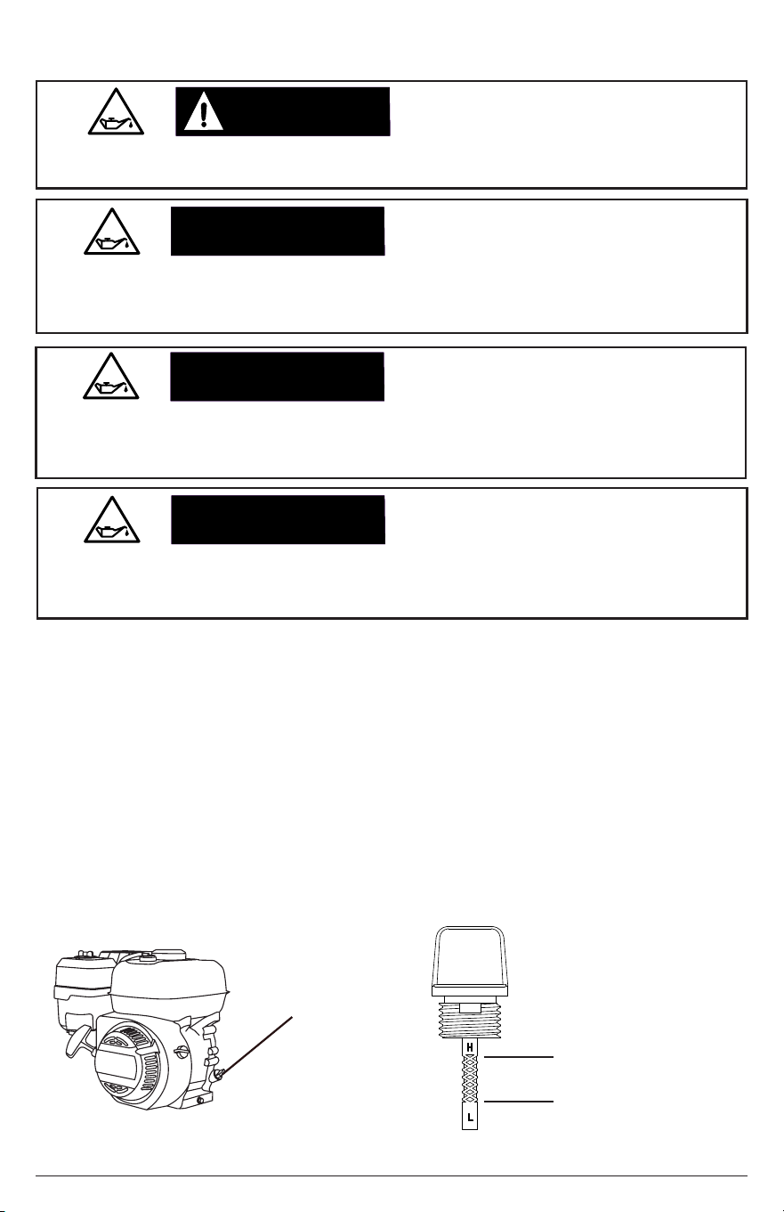
Upper Oil Limit
Lower Oil Limit
Engine Oil
Dipstick
Fig. 19
Fig. 20
NOTICE
The low oil sensor (if equipped) will automatically stop the engine when the oil level falls
below the safe limit. To avoid an unexpected shutdown, check the oil level regularly, ll to
the upper limit, and always operate engine on a level surface.
LOW OIL SENSOR
NOTICE
NOTICE
The engine is shipped from the factory without oil. Running the engine without oil will
result in severe engine damage and void the warranty. To avoid causing engine damage
and voiding the warranty, ll the engine with the recommended oil type before starting.
Oil is a major factor in the performance and service life of any engine. Using the incorrect
oil may damage the engine and void the warranty. To avoid causing engine damage and
voiding the warranty, check and change oil as required using the correct engine oil.
FILL ENGINE BEFORE USE
USE CORRECT ENGINE OIL
1. Check the oil with the trailer on level pavement.
2. Unscrew the engine oil dipstick (Fig. 19), remove it and wipe the dipstick clean.
3. Place the dipstick into the ller neck leaving it to rest on the lip; do not thread in.
4. Remove the dipstick from the ller neck then check the oil level. Oil level should be
at the upper oil limit on the dipstick (Fig. 20).
5. If the level is low, add the recommended oil to the crankcase until the level reaches
the upper limit of the dipstick. Do not overll. See Engine Owner’s Manual for the
recommended oil.
6. Thread in the dipstick, hand tighten.
CAUTION:CAUTION:
Hot oil can cause serious burns. To prevent getting burned when changing or checking
the engine oil, wear gloves and change the oil when the engine is warm but not hot.
HOT OIL
Checking the Engine Oil
Page 27
WARNING:WARNING:
NOTICE
NOTICE
NOTICE
Old gasoline can create deposits that clog fuel systems causing hard starting and poor
performance. Damage caused by old fuel is not covered by warranty. To minimize
deposits, avoid old fuel related performance issues, and prevent costly repair work, do
not use gasoline that is older than 30 days.
Using gasoline with an alcohol blend greater than 10% (E10) will damage the engine.
Damage caused by using an alcohol blend of 15% (E15), 85% (E85), or any other alcohol
blend higher than 10% (E10) is not covered under warranty. To avoid engine damage
caused by an alcohol blend that is too high, use gasoline with 10% (E10) alcohol or lower.
The use of fuel system cleaning additives can damage the engine and fuel systems.
Damage caused by the use of fuel system cleaning additives is not covered by warranty.
To avoid engine and fuel system damage, do not use any fuel system cleaning additives.
Gasoline is highly ammable and gasoline vapors are extremely explosive. Fire and
explosions can cause severe burns and/or death. Keep gasoline away from ames,
sparks, and other ignition sources. Refuel outdoors in a well-ventilated area with the
engine stopped and cool. Wipe up any spilled gasoline and allow engine to dry before
starting. Keep a re extinguisher handy while refueling. Do not operate engine with leaks
in the fuel system. Do not store gasoline near other ammable materials. Store fuel in a
clean, OSHA-approved container in a secured location away from the work area.
OLD GASOLINE
ALCOHOL BLENDS
GASOLINE ADDITIVES
REFUELING
Checking Fuel
CAUTION:CAUTION:
Gasoline vapor can build up inside the fuel tank creating pressure. This pressure may
increase when the engine is hot from running. Opening the fuel tank under pressure can
cause rapid escape of ammable vapors and possible fuel spills that may ignite from
contact with hot engine surfaces resulting in burn hazard. To avoid these hazards, always
allow the engine to cool for at least 2 minutes before removing fuel cap and loosen the
fuel cap slowly to relieve any pressure in the tank.
FUEL TANK PRESSURE
NOTICE
NOTICE
Maximum Fuel Level
Page 28
It is important to prevent gum deposits from forming in essential fuel system parts, such
as the carburetor, fuel lter, fuel hose or tank during storage. Alcohol-blended fuels (also
called gasohol, ethanol, or methanol) attract moisture, which leads to separation and
formation of acids during storage. Acidic fuel and gum deposits can damage the engine’s
fuel system while in storage. Damage caused by the use of old, stale, or contaminated
fuel are not covered under warranty.
Overlling the fuel tank can result in carbon canister damage (if equipped), poor engine
performance, and void the warranty. To avoid these hazards, do not ll the fuel tank
above the maximum level.
GASOLINE STORAGE
DO NOT OVERFILL FUEL TANK
1. Check the fuel with the engine o and the trailer on level pavement.
2. Remove the fuel tank cap, check level then ll fuel tank if needed. For the fuel cap
location see the FEATURES AND CONTROLS section of the Engine Owner’s Manual.
3. Do not use gasoline that is older than 30 days. Use only fresh unleaded gasoline
with a minimum octane rating of 87 and no more than 10% ethyl alcohol. Do not mix
oil with the gasoline.
4. Do not ll the fuel tank above the maximum fuel level to allow room for fuel expansion.
5. Replace fuel tank cap. Never run engine without the fuel cap in place and tightened.
NOTE: Using a fuel stabilizer (sold separately) when storing gasoline can help prevent
problems related to storing ethanol alcohol blended gasoline. Always follow the instructions
provided by the fuel stabilizer manufacturer to mix and use correctly.
NOTICE
WARNING:WARNING:
Page 29
STARTING THE ENGINE
Attempting to start the engine incorrectly can result in engine and/or pump damage, and
may cause serious injury or death. To avoid these hazards, be sure to read, understand,
and follow the steps outlined in the OPERATING CHECKLIST section of the owner’s
manual before starting the engine, and follow all the guidelines for proper use of the
SIMPSON Water Trailer.
OPERATING CHECKLIST
Starting the Engine
1. Complete the steps in the OPERATING CHECKLIST section of this manual before
starting the engine. Failure to do so could cause damage to the engine. If needed,
refer to your Engine Owner’s Manual for specic starting instructions. Lastly, make
sure the pump is primed and the trailer is ready for the desired operation.
2. Turn the engine switch to the ON position.
3. Slide the fuel valve to the ON position.
4. Slide the throttle to the RUN position.
OFF
ON
OFF
ON
This pump will not prime when dry. Running the pump dry without priming can damage the
pump assembly and seals. Damage caused by running dry is not covered by warranty.
To avoid damaging the seals and pump assembly, do not run the pump when it is dry
without priming.
PUMP PRIMING
WARNING:WARNING:
NOTICE
Page 30
NOTE: The starting position of the choke will vary depending on the engine temperature. If
starting a cold engine, move the choke lever towards the CHOKE position. If starting a warm
engine, move the choke lever towards the RUN position.
5. Slide the choke to CHOKE for starting a COLD engine. Slide to RUN for a warm
engine
CHOKE
RUN
Rapid retraction (also known as kickback) of the engine recoil starter cord will pull your
hand and arm towards the engine faster than you can let go of the handle resulting in
sprains, broken bones, lacerations, and/or traumatic amputations. Kickback is caused
by damage to the engine crankshaft key, compression release failure, and/or improper
starting techniques. To avoid kickback follow the appropriate maintenance schedule,
starting instructions and have repair work done by an authorized service center.
RAPID RETRACTION
Never allow the tank water level to fall below a level of one inch above the outlet pipe of
the tank. If the tank fully drains, pump damage may occur from lack of water and you will
only be able to rell the tank from a pressurized water source. When you approach this
level, TURN OFF THE ENGINE.
PUMP DAMAGE
CHOKE
RUN
7. Once the engine starts, slowly move the choke lever to RUN as the engine runs. If
the engine falters, move the choke toward CHOKE until the engine has warmed up.
NOTE: If the engine should not start
after two pulls, squeeze the gun trigger
to release stored pressure. Then, try
again to start the engine.
6. Pull the recoil slowly until resistance is felt, then pull rapidly to start the engine. Do
not allow the starter grip to snap back. Return it gently by hand.
Page 31
SHUTTING DOWN THE ENGINE
TROUBLESHOOTING
ISSUE POSSIBLE CAUSE SOLUTION
The fuel tank is empty. Add fresh fuel.
Refer to the STARTING
THE ENGINE section of
this manual for the correct
choke position.
Engine choke is in the wrong
position.
The spark plug lead is not
attached to the plug.
Connect spark plug lead.
Engine switch is in the OFF
position.
Turn the engine switch to
the ON position.
Engine fuel valve is turned OFF.
Turn fuel valve ON.
Engine oil is low. If the engine
is equipped with a Low Oil
Sensor, the engine will not start.
Check engine oil level. Fill per
the Engine Owner’s Manual.
Engine will not start.
Refer to the Engine
Owner’s Manual for more
engine troubleshooting
information.
OFF
ON
OFF
ON
1. Slide the throttle to the SLOW position. Allow the speed of the engine to decrease.
2. Turn the engine switch to OFF.
3. Slide the fuel switch to OFF.
Page 32
MAINTENANCE
For safety reasons, the manufacturer recommends all service and repairs be
performed by an authorized service center. All warranty replacement and repairs must
be performed by an authorized distribution or service center. To nd an authorized
service center near you, to make a warranty claim or for authorized warranty repair,
call 1-833-362-7368 or contact through email at [email protected]
It is the responsibility of the owner and / or operator to have all scheduled maintenance
completed before transporting or operating the SIMPSON Water Trailer. Be sure
to follow the inspection and maintenance recommendations as listed in all of the
manuals that came with this unit.
Pump Maintenance
Before each use, check the pump for loose or damaged parts and any other condition
that may aect proper operation. Be sure all safety guards are in place and in proper
working order. Inspect all air vents and cooling slots to ensure they are clean and
unobstructed. For safety reasons, the manufacturer recommends all service and
repairs be performed by an authorized service center. To nd an authorized service
center near you, to make a warranty claim or for authorized warranty repair, call
1-833-362-7368 or contact through email [email protected]
CAUTION:CAUTION:
Improper engine and pump maintenance as well as failing to correct problems before
operation could void the warranty and may result in property damage and injury. To
prevent these hazards, follow the maintenance procedures listed in this manual and any
other manual that came with the product.
MAINTENANCE
NOTICE
Water can damage the engine components if allowed to enter through cooling slots or
other holes. Damage caused by water intrusion is not covered under warranty. To avoid
engine water damage, do not use a pressure washer, garden hose, or any other sources
of running water to clean the engine and never submerge the pump/engine in any liquids.
CLEANING
Exterior Pump Cleaning
Always clean the pump with the engine o and cool. To clean the pump, rst use an
air compressor set at 25 PSI to clear dirt and debris from the pump surfaces, vents
and cooling slots. Next, wipe the exterior with a damp cloth.
WARNING:WARNING:
When performing maintenance, you may be exposed to hot surfaces, water pressure, or
moving parts that can cause serious injury or death. Always disconnect spark plug wire
and let the engine cool before performing any maintenance or repair. The engine contains
ammable fuel. Do not smoke or work near open ames while performing maintenance.
RISK OF BURNING
WARNING:WARNING:
Never modify the product or any part of it. Damage or personal injury could result.
MODIFICATION INJURY
Page 33
Interior Pump Cleaning
Keeping the pump clean will allow it to perform its best and prolong the life of the
pump. Never pump water from a standing source without using a lter / screen. Do
not store the pump without draining the pump housing. Do not allow dirt or debris to
dry inside the pump housing. You can clean the interior of the pump by following the
steps below:
1. Disconnect the spark plug lead from the engine. Place it to the side of the plug.
2. Drain the system as outlined in DRAINING THE SYSTEM FOR STORAGE section
of this manual.
3. Using a screw or nut driver, loosen the worm screw clamps (Fig. 21). Carefully
remove them from the anges then slide them to the right.
NOTICE
Using chemical cleaners and/or corrosive liquids can damage the pump seals and internal
components. Damage caused by chemical cleaners and corrosive liquids is not covered
under warranty. To avoid damaging pump seals and components, do not use chemical
cleaners or corrosive liquids to clean the components inside the pump housing.
CHEMICAL CLEANERS
WARNING:WARNING:
This product has many parts that move at high speeds. Moving parts can cause crushing
injuries, broken bones, severe lacerations, and/or traumatic amputations. To prevent
injury, never place ngers, hands, feet, or other body parts near running engine. Never
operate product with covers, shrouds, or other guards removed. Do not wear loose-tting
clothing, dangling drawstrings, or any other hanging items that could become entangled
in moving parts while operating. Tie up long hair and remove jewelry before operating.
MOVING PARTS
Fig. 21
Worm screw clamps
Page 34
5. With the assistance of another person, lift the engine/pump assembly o of the bolts
and turn it 180 degrees so the pump faces the driver’s side of the trailer.
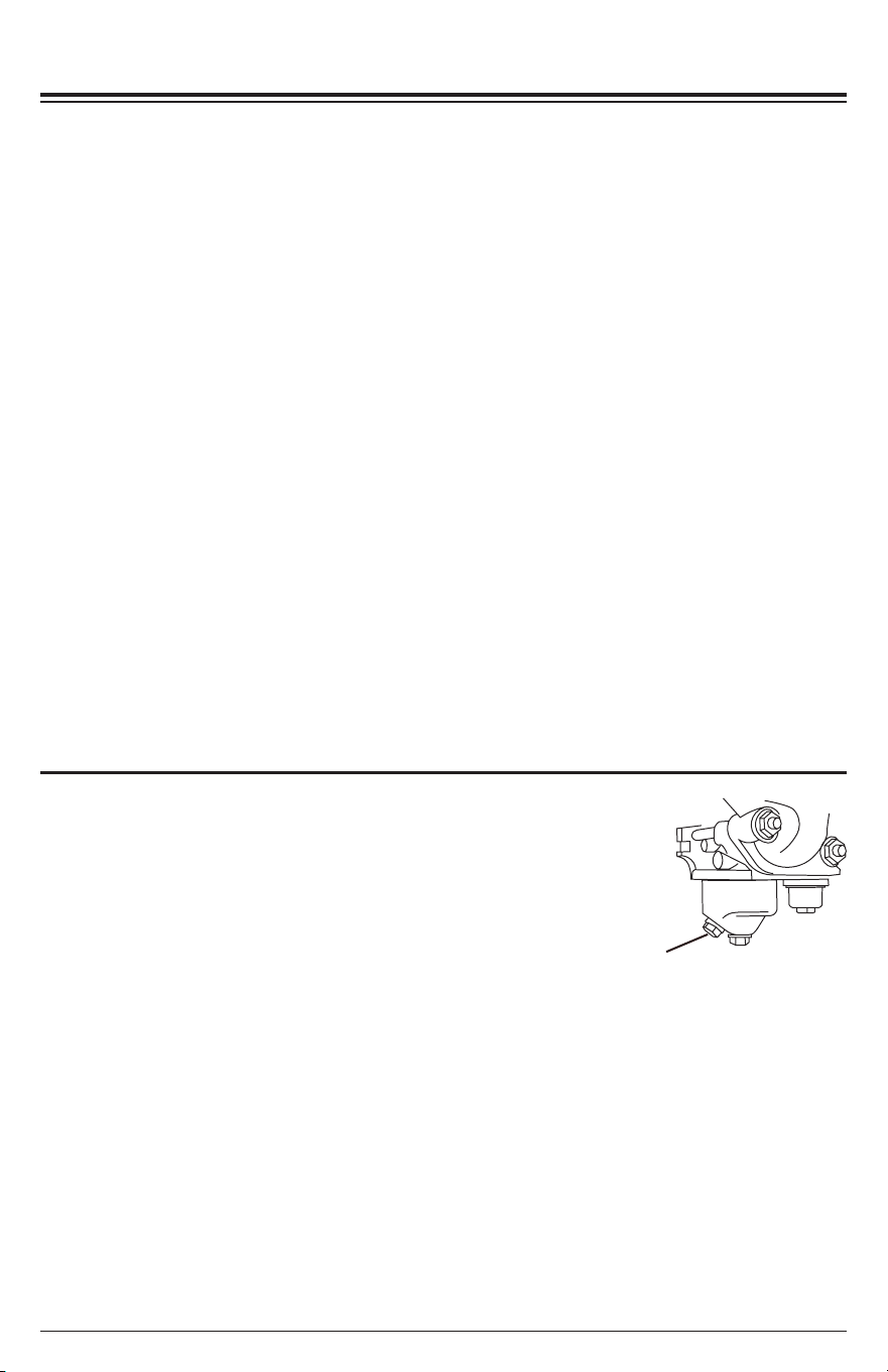
6. Remove the outer pump housing cover bolts (Fig. 23 - A)
7. Remove the outer pump housing cover (Fig. 23 - B ) and its rubber seal (Fig. 23 - C).
8. Remove the check valve (Fig. 23 - D).
9. Remove the impeller/volute (Fig. 23 - E).
10. Remove all dirt and debris from the components then rinse them clean with fresh
water. Do not use chemicals to clean the internal pump components as they may
damage the seals.
11. Reassemble the pump components making sure the rubber seals are in their
proper locations and do not get pinched or damaged during reassembly.
Fig. 22
Mounting nuts
Fig. 23
C
E D B A
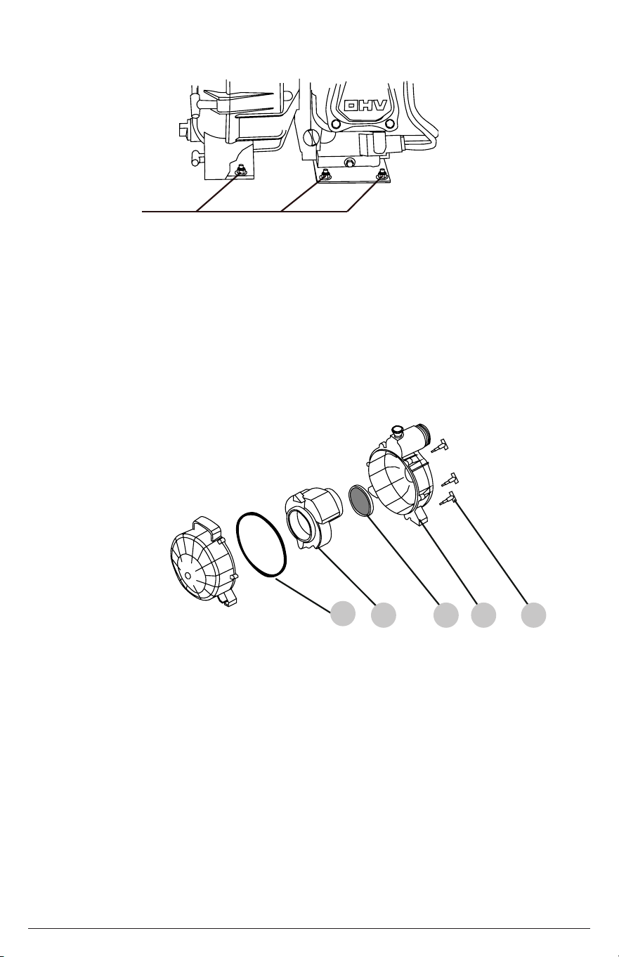
4. Using an open end wrench, loosen and remove the six nuts (four under the engine,
two under the pump) and their washers that hold the unit to the frame (Fig. 22).
12. With the assistance of another person, lift the engine/pump assembly and rotate it
back into position on the bolts.
13. Place the nuts and washers back onto the mounting bolts. Tighten with an open
end wrench.
14. Place the worm screw clamps back onto the ttings. Tighten.
15. Place the spark plug lead back onto the spark plug.

Page 35
Engine Maintenance
Before each use, check the engine for loose or damaged parts, signs of oil or fuel
leaks and/or any other condition that may aect proper operation. Always keep all
safety guards in place and in proper working order. Repair or replace all damaged or
defective parts immediately.
For safety reasons, the manufacturer recommends all engine service and repairs
(including emission control devices and systems) to be performed by an authorized
service center. All warranty replacements or repairs must be performed by an
authorized distribution or service center. To nd an authorized service center near
your, obtain information about how to make a warranty claim or to make arrangements
for authorized warranty repairs, please call 1-833-362-7368 or
contact through
email
For all other information on engine maintenance, refer to your Engine Owner’s Manual.
Plumbing Maintenance
The plumbing of the SIMPSON Water Trailer was designed to give years of worry-free
life. However, it is important to monitor all connections for leaks. If the trailer is not to
be used for an extended period of time, make sure to drain the trailer of water as talked
about in the DRAINING THE SYSTEM FOR STORAGE section of the manual. It is of
utmost importance to winterized the system if freezing weather is expected. Routinely
rotate all valves to make sure they move freely without binding.
Trailer Maintenance
Inspect the nozzles on the spray bar for debris that may cause the spray pattern to be
inconsistent. Remove large pieces of debris with needle-nosed pliers then sweep the
orice of the nozzle with a small bottle brush to remove any remaining particles.
For trailer maintenance, safety and towing information, please read and fully understand
the “Utility Trailer Owner’s Manual” and the “Mobile Pressure Washing Trailer / Water
Trailer Additional Instructions” sheet before towing the trailer.
Page 36
ENGINE LONG-TERM STORAGE
Storing for Two Months or Less (or when freezing temperatures are expected)
1. Make sure the engine is o and cool.
2. Fill the fuel tank per the OPERATING CHECKLIST section of this manual, and then
add a fuel stabilizer per the manufacturer’s recommendations.
NOTE: Using a fuel stabilizer (sold separately) when storing gasoline may
help prevent the problems related to alcohol blended fuels in outdoor power
equipment engines. Always follow the instructions provided by the fuel stabilizer
manufacturer to mix and use correctly.
3. Make sure the
water in the tank is a minimum of 1” above the outlet pipe (Fig. 9).
4. Move the FLOW valves to the BYPASS position (Figs. 1 and 4).
5. Move the TANK valve to OPEN to begin purging air and priming the pump (Figs. 1-2).
6. Ensure the pump is primed and air is fully purged from the pump. If you start to
remove the primer cover and water begins to ow out, it is primed. If not, remove the
cover and ll the pump with water (Fig. 8). Thread the cover back onto the funnel;
tighten.
7. Start the engine per the STARTING THE ENGINE section of this manual.
Allow the engine to run for a minimum of two minutes to allow the fuel stabilizer
to circulate throughout the fuel system.
8. Shut o the engine by using the SHUTTING DOWN instructions.
9. Drain the tank, pump and plumbing system per the DRAINING THE SYSTEM FOR
STORAGE section of this manual.
Storing for More Than Two Months
1. Make sure the engine is o and cool.
2. Drain the tank, pump and plumbing system per the
DRAINING THE SYSTEM FOR STORAGE section
of this manual.
3. Using an appropriate container, completely drain
the fuel system by removing the drain screw on the
bottom of the carburetor (Fig. 24). Open the fuel tank
cap to make sure all of the gasoline has drained from the system. Thread in the drain
screw once the fuel is removed.
4. Change the engine oil; see the Engine Owner’s Manual for reference.
5. Remove any dirt or debris from the area around the spark plug. Using a spark plug
wrench, remove the spark plug.
6. Pour 0.5 ounces (15mL) of new engine oil into the engine combustion chamber.
7. Slowly crank the engine by pulling on the recoil two times to distribute the oil and
lubricate the cylinder.
8. Hand thread the spark plug then tighten with the spark plug wrench. Torque to meet
the requirements set forth in the Engine Owner’s Manual.
Fig. 24
Drain screw
Page 37
DRAINING THE SYSTEM FOR STORAGE (WINTERIZE)
When you will not be using the trailer for an extended period of time or there is a
chance of freezing weather, you should drain the system.
2.
Using a screw or nut driver, loosen the worm screw clamp (Fig. 25 - A). Carefully
remove it and the manifold plug from the tee ange.
3. Remove the drain plug on the bottom of the pump (Fig. 25 - B).
1. Ensure the trailer is as level as possible.
4. Remove the primer cover from the pump allowing air into the pump (Fig. 25 - C).
5. As the system drains, operate the FLOW valves (Figs. 1 and 4) to allow any trapped
water to drain.
6. Once the water has stopped owing, replace the caps and manifold plug; tighten.
C
Fig. 25
7. Move the TANK valve to the CLOSED position (Fig. 1-2).
DRAINING THE SYSTEM
A
4. Move the TANK valve to the OPEN position to allow the tank to empty (Fig. 1-2).
8. Using a screw or nut driver, loosen the hose clamp (Fig. 26). Carefully remove the
hose and lower it, allowing residual water to drain.
9. Remove the drain plugs from the bottom of the spray bar near each nozzle (Fig. 27).
10. Allow any trapped water to drain from the hose and the spray bar.
Fig. 26
Fig. 27
11. Thread in the drain plugs; tighten.
12. Align the hose assembly back with the manifold, position the clamp and tighten.
B

Page 38
LIMITED WARRANTY
Industrial / Rental Products
WARRANTY COVERAGE TERMS:
THIS WARRANTY DOES NOT COVER:
Damage resulting from shipping (claims must be led with freighter), accident, abuse, acts of God, misuse or neglect. This
warranty also does not cover damage from repairs or alterations performed by non-factory authorized personnel or failure to install
and operate equipment according to the guidelines put forth in the instruction manual. The manufacturer will not be liable to any
persons for consequential damage, for personal injury or for commercial loss.
RESPONSIBILITY OF ORIGINAL PURCHASER (INITIAL USER):
To process a warranty claim on your SIMPSON® water trailer, report the concern to 1-833-362-7368 or cservice@
fna-group.com for authorization and direction to the nearest authorized service center in your area.
Retain original cash register receipt as proof of purchase for warranty work.
Use reasonable care in the operation and maintenance of the product as described in the Owner’s Manual.
WHAT THIS WARRANTY DOES NOT COVER:
WARRANTY COVERAGE PERIODS:
ENGINE AND EMISSIONS CONTROL SYSTEM
• Three (3) years from date of purchase (see engine manual for details).
PUMP (DEFECTS IN MATERIAL AND WORKMANSHIP)
• Five (5) years from date of purchase
FRAME (DEFECTS IN MATERIAL AND WORKMANSHIP)
• One (1) year from date of purchase
ACCESSORIES (DEFECTS IN MATERIAL AND WORKMANSHIP)
• Ninety (90) days from date of purchase
The manufacturer of this product agrees to repair or replace designated parts that prove defective within the warranty period
listed below at the manufacturer’s sole discretion. Specic limitations / extensions and exclusions apply.
This warranty covers defects in material and workmanship and not parts failure due to normal wear, depreciation, abuse,
accidental damage, negligence, improper use, maintenance, water quality or storage. Normal wear items include, but are not
limited to, items such as valves and seals, which are not covered by this warranty. To make a claim under the terms of the
warranty, all parts said to be defective must be retained and available for return upon request to a designated Warranty Service
Center for warranty inspection. The judgments and decisions of the manufacturer concerning the validity of warranty claims are
nal.
This limited warranty extends only to the consumer who originally purchased the new product from the manufacturer or from
an authorized seller of the product. It does not extend to any subsequent owner or through consumer transfer of the product,
and cannot be provided by any unauthorized seller of the product. Factory authorized and trained Warranty Service Centers will
honor the terms of all component warranties and satisfy claims of the appropriate warranty provisions.
This warranty replaces all other warranties, express or implied, including without limitation and warranties of merchantability
or tness for a particular purpose and all such warranties are hereby disclaimed and excluded by the manufacturer. The
manufacturer’s warranty obligation is limited to repair and replacement of defective products and provided herein and the
manufacturer shall not be liable for any further loss, damages, or expenses - including damages from shipping, accident, abuse,
acts of God, misuse, or neglect. Neither is damage from repairs using parts not purchases from the manufacturer or alterations
performed by non-factory authorized personnel. Failure to install and operate equipment according to the guidelines put forth in
the instruction manual shall void warranty.
• Freight damage
• Damage due to chemical deterioration, salt water, rust or corrosion
• Damage caused by parts or accessories not obtained from an authorized dealer or not approved by the manufacturer
• Normal wear of moving parts or components aected by moving parts
• Consumable parts such as: Fuel lter, air lter, spark plug(s), recoil starter rope, oil and lubricant(s)
• Normal periodic maintenance work such as carburetor cleaning and engine oil draining
• Freeze damage

Page 39
THIS PAGE WAS INTENTIONALLY LEFT BLANK
NOTES

Page 40
THIS PAGE WAS INTENTIONALLY LEFT BLANK

Page 41
THIS PAGE WAS INTENTIONALLY LEFT BLANK

Part Number 7119888 / ENGLISH REV E - 6/2025
READ THIS MANUAL CAREFULLY BEFORE OPERATION
Failure to follow the instructions and safety precautions in this manual can result
in property damage, serious injury and/or death.
SAVE THIS MANUAL FOR FUTURE REFERENCE
Copyright © 2025 FNA-Group, Inc. All rights reserved.