
14
17
18
16
15
(2x)
43
(2x)
42
44
41
40
37
(2x)
8
(4x)
46
35
25
20 21
72
8 14
19
70
35 36
37 46
47
60
15 16
17 18
66
41 43
68
42 43
67
10 11
12 13
64
10
11
12
13
19
20
21
27 28
30 31
33 34
63
47
(2x)
50
37 38
39 40
48
61
38
48
(2x)
39
36
37
(7x)
27
28
33
(4x)
30
31
34
(4x)
32
9
7
7
62
25
65
MILWAUKEE TOOL
l
www.milwaukeetool.com
13135 W. LISBON RD., BROOKFIELD, WI 53005
Drwg. 3
0
00
EXAMPLE:
Component Parts (Small #)
Are Included When Ordering
The Assembly (Large #).
FIG. NOTES
50 A clean, dry surface is essential
for proper performance for any
adhesive system. The area
intended for application of any
adhesive label or nameplate must
be prepared by cleaning with
isopropyl alcohol. The solvent is
to be applied with a clean, lint free
applicator and the surface allowed
to dry before applying the label or
name plate.
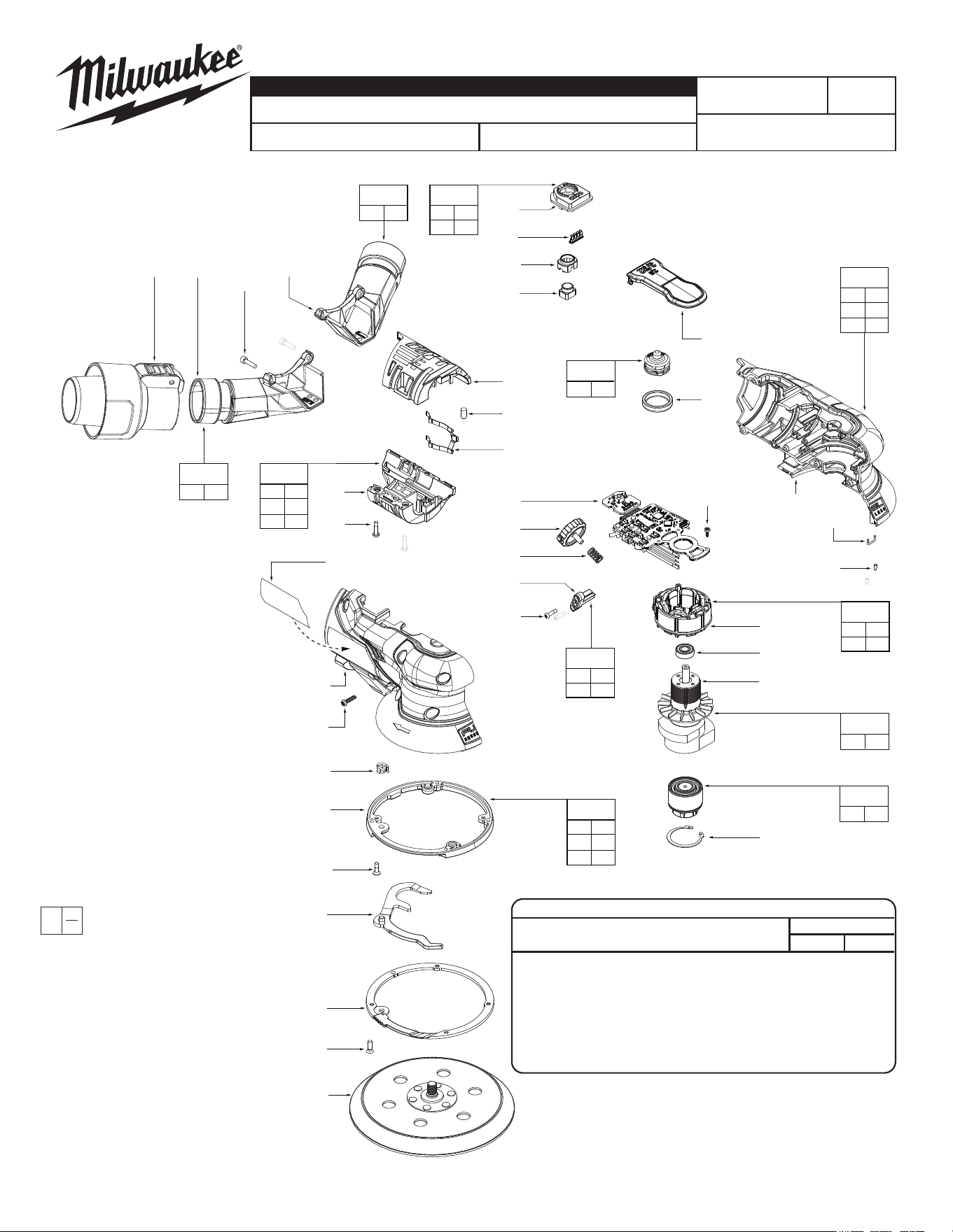
SCREW TORQUE SPECIFICATIONS
FIG. PART NO. WHERE USED
SEAT TORQUE
kgf-cm lb-in
6 --------------- Hall Sensor Holder 2±.5 1.7±0.4
8 05-88-0106 Hall Board 2.7±.5 2.3±0.4
15 --------------- Speed Dial Cap to Housing 5±1 4.3±0.8
33 --------------- Wrench Ring to Housing 7±1 6±0.8
34 --------------- Wrench Frame to Ring 6±2 5±1.7
37 05-78-0044 Housing Support to Cover 9±1 8±0.8
37 05-78-0044 Battery Cage 9±1 8±0.8
43 --------------- Vacuum Tube to Housing 6±1 5±0.8
SERVICE PARTS LIST
BULLETIN NO.
54-38-2705
SPECIFY CATALOG NO. AND SERIAL NO. WHEN ORDERING PARTS REVISED BULLETIN DATE
May 2025
M12 FUEL™ 6" Random Orbital SANDER (3/32")
WIRING INSTRUCTION
See Page 3
CATALOG NO. 2584-20 SERIAL NO. P16A
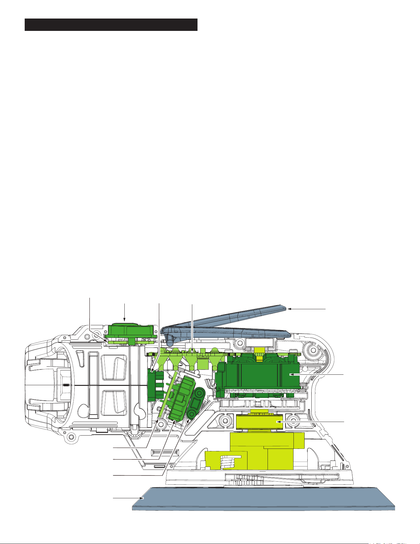
SERVICE BILL OF MATERIAL (BOM) LISTING
Motor (19)
On/Off
Switch (10)
Rotor (21)
PCBA
(14)
Speed Dial
Board
Terminal
Board
UI Board
Speed Dial (17)
Dial Retention
Plate (16)
Sanding Pad (32)
Paddle Trigger (9)
FIG. PART NO. DESCRIPTION OF PART NO. REQ.
2 --------------- Hall Sensor Spring (1)
3 --------------- Hall Sensor Holder (1)
4 --------------- Hall Sensor Magnet (1)
5 --------------- Cover Half of Spring Retention (1)
6 --------------- M2 x 7.8mm ST Screw (3)
7 --------------- Sealing Foam (1)
8 05-88-0106 M2 x 5.5mm Pan Head Torx T-8 Screw (4)
9 31-92-0044 Paddle Trigger for 3/32" Paddle (1)
10 --------------- UI Bezel (1)
11 --------------- Light Pipe (1)
12 --------------- Power Mode Lense (1)
13 --------------- UI Power Bottom (1)
14 --------------- PCBA for the 3/32" version (1)
15 --------------- M2.6 x 10mm Torx T-8 Taptite Screw (2)
16 --------------- Dial Retention Plate (1)
17 --------------- Speed Dial (1)
18 40-50-0200 7 x 11mm Spring (1)
19 --------------- Motor Field, 12V-DC BL45 (1)
20 02-04-0071 Deep Groove Ball Bearing (1)
21 --------------- Rotor (1)
23 --------------- Rubber Gasket (1)
24 --------------- BP Attachment Nut (1)
25 --------------- Internal Inverted Retaining Ring (1)
26 --------------- Quick Change Hinge (1)
27 --------------- Torsion Spring (1)
28 --------------- Quick Change Mechanism Ring (1)
30 --------------- Quick Change Wrench (1)
31 --------------- Quick Change Frame Ring (1)
32 --------------- 6" Pad for 3/32 Orbit Sander (1)
33 --------------- M3 x Flat Head Torx T-10 Taptite Screw (4)
FIG. PART NO. DESCRIPTION OF PART NO. REQ.
34 06-82-0209 M3 x 10mm Flat Hd. Phillips B Screw (4)
35 --------------- Handle Support (1)
36 --------------- Handle Cover (1)
37 05-78-0044 M3 x 12mm Pan Hd. Torx Taptite Screw (9)
38 --------------- Battery Support (1)
39 42-70-0480 Spring Clip (1)
40 --------------- Battery Cover (1)
41 --------------- Left Hand Vacuum Port (1)
42 --------------- Right Hand Vacuum Port (1)
43 --------------- M3 x 12mm Cap Hd. Hexagon M Screw (2)
44 43-76-0059 Vacuum Adaptor (1)
46 42-70-0080 Wire Clip (1)
47 45-30-0047 Rubber Slug (2)
48 45-30-0100 Rubber Slug, OD5 x 9 (2)
50 12-20-0644 Service Nameplate (1)
60 14-46-0133 Handles Kit (1)
61 14-46-0184 Battery Support Kit (1)
62 14-46-0187 Sensor Trigger Assembly (1)
63 14-46-0319 Quick Change Mech Kit (1)
64 14-46-0261 UI Bottom Kit (1)
65 14-46-0299 Retention Assembly (1)
66 14-46-0269 Speed Dial Kit (1)
67 14-46-0323 Right Hand Vacuum Port Kit (1)
68 14-46-0324 Left Hand Vacuum Port Kit (1)
70 14-46-0203 PCBA / Motor Assembly for 3/32" (1)
72 14-46-0289 Rotor Assembly for 3/32" (1)
80 49-36-2583 6" Hook & Loop Backing Pad - Soft (1)
- Accessory (Not Shown)
81 49-36-2585 6" PSA Pressure & Sensitive Adhesive (1)
- Soft - Accessory (Not Shown)
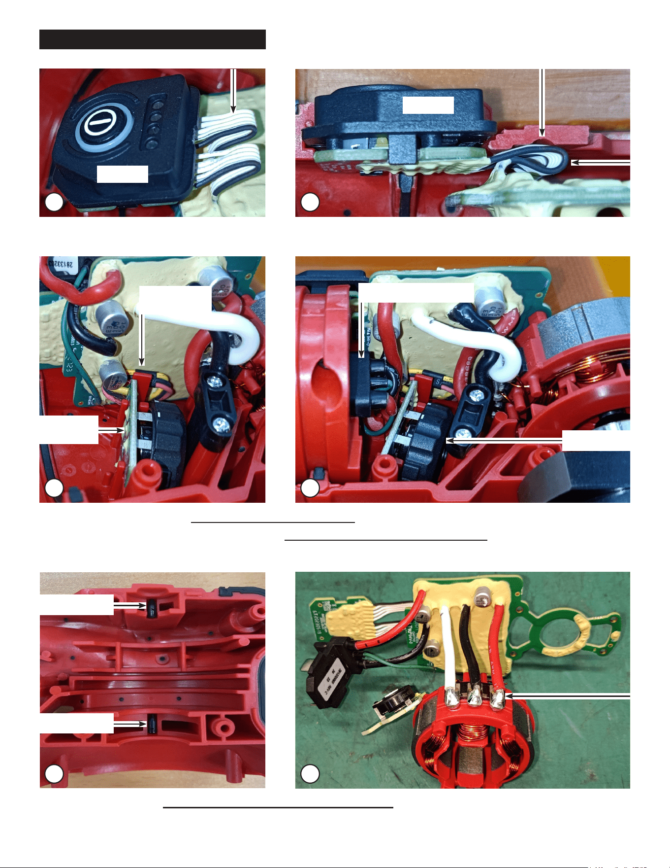
WIRING
1 2
- TheUIWiresshouldbefolded(Fig.1)rstandthenroutedinsidetheHousing(Fig.2)
3 4
- The Speed Dial Board Wires should be routed behind the rib (Fig. 3)
- The 3 Terminal Board Wires should be routed to avoid them being above the Speed Dial. (Fig. 4)
There should be no wires above the Speed Dial.
Speed Dial
Terminal Board Wires
UI Panel
Speed
Dial Board
Speed Dial
Board Wires
5
- The Rubber Slugs (47) should be assembled in the SAME direction. (Fig. 5)
- Solder phase wires to stator (Fig. 6)
6
Rubber Slug
Rubber Slug
UI Panel