ETL-ES-Brentford-WH25
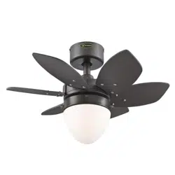
OWNER'S MANUAL
MANUAL DEL USUARIO
Brentford
Please write model number here for future reference:
Por favor, incluya el número del modelo aquí para futura
referencia:
Net Weight: 23.37 LBS
Peso Neto: 10.60 KGS

2
ETL-ES-Brentford-WH25
TOOLS REQUIRED
Phillips Screwdriver Wire Cutters Pliers Step Ladder
SAFETY TIPS
OBSERVE THE FOLLOWING: READ AND SAVE THESE INSTRUCTIONS
WARNING: TO REDUCE THE RISK OF FIRE, ELECTRIC SHOCK, OR PERSONAL INJURY, MOUNT TO OUTLET BOX MARKED 'ACCEPTABLE FOR FAN SUPPORT OF 35 LBS (15.9 KG) OR LESS'
AND USE MOUNTING SCREWS PROVIDED WITH THE OUTLET BOX AND/OR SUPPORT DIRECTLY FROM BUILDING STRUCTURE. MOST OUTLET BOXES COMMONLY USED FOR THE
SUPPORT OF LUMINARIES ARE NOT ACCEPTABLE FOR FAN SUPPORT AND MAY NEED TO BE REPLACED. CONSULT A QUALIFIED ELECTRICIAN IF IN DOUBT.
1. Installation work and electrical wiring must be done by qualified person(s) in accordance with all applicable codes and standards (ANSI/NFPA 70), including fire-rated construction.
2. Use this unit only in the manner intended by the manufacturer. If you have any questions contact the manufacturer.
3. After making the wire connections, gently push connections into outlet box with wire nuts pointing up. The wires should be spread apart with the grounded conductor and the
equipment-grounding conductor on one side of the outlet box and ungrounded conductor on the other side of the outlet box.
4. Before you begin installing the fan, switch power off at service panel and lock service disconnecting means to prevent power from being switched on accidentally. When the
service disconnecting means cannot be locked, securely fasten a prominent warning device, such as a tag, to the service panel.
5. Be cautious! Read all instructions and safety information before installing your new fan. Review the accompanying assembly diagrams.
6. When cutting or drilling into wall or ceiling, do not damage electrical wiring and other hidden utilities.
7.
Make sure the installation site you choose allows the fan blades to rotate without any obstructions. Allow a minimum clearance of 7 feet from the floor to the trailing edge of the blade.
8. To reduce the risk of fire, electric shock, or personal injury, this fan must be mounted to an outlet box marked suitable for fan support, and use the mounting screws provided with
the outlet box. (Mounting must support at least 35 lbs.)
9. WARNING! Do not bend blade holders during installation to motor, balancing or during cleaning. Do not insert foreign object between rotating blades.
10. Attach the mounting bracket using only the hardware supplied with the outlet box. Fan is only to be mounted to an outlet box marked “Acceptable for Fan Support”.
11. WARNING! To reduce the risk of fire or electric shock, do not use this fan with any solid state fan speed control device, or variable speed control.
12. If this unit is to be installed over a tub or shower, it must be marked as appropriate for the application.
13. NEVER place a switch where it can be reached from a tub or shower.
14. The combustion airflow needed for safe operation of fuel-burning equipment may be affected by this unit’s operation. Follow the heating equipment manufacturer’s guideline safety
standards such as those published by the National Fire Protection Association (NFPA), and the American Society for Heating, Refrigeration and Air Conditioning Engineers (ASHRAE)
and the local code authorities.
15. Before servicing or cleaning unit, switch power off at service panel and lock service disconnecting means to prevent power from being switched on accidentally. When the service
disconnecting means cannot be locked, securely fasten a prominent warning device, such as a tag, to the service panel.
16. All set screws must be checked and re-tightened where necessary before installation.
17. The appliance is not intended for use by young children or infirmed persons without supervision. Young children should be supervised to ensure they do not play with the appliance.
18. Suitable for use in wet locations when installed in a GFCI protected branch circuit.
19. Use only with light kits marked ‘suitable for use in wet locations’.

3
ETL-ES-Brentford-WH25
HERRAMIENTAS NECESARIAS
Destornillador Phillips Pinzas de corte Pinzas Escalera de mano
CONSEJOS DE SEGURIDAD
1. El trabajo de instalación y el cableado eléctrico los deben efectuar personas calificadas cumpliendo con todos los códigos y las normas aplicables (ANSI/NFPA 70), incluyendo las de incendio.
2. Use esta unidad sólo de la manera en que el fabricante quiere que se haga. Si tiene dudas, llame al fabricante.
3. Después de hacer las conexiones, empuje con cuidado las conexiones dentro de la caja de embutir con los conectores de cables mirando hacia arriba. Se deben separar los cables: el conductor de puesta
a tierra y el conductor de puesta a tierra del equipo a un lado de la caja de embutir, y el conductor que no tiene puesta a tierra del otro lado de la misma.
4. Antes de comenzar a instalar el ventilador, apague la alimentación en el panel de servicio y bloquee el medio de desconexión del servicio para evitar que se encienda accidentalmente. Cuando no se puede
bloquear el medio de desconexión del servicio eléctrico, fije de manera segura un dispositivo de advertencia prominente, como un rótulo, al panel de servicio.
5. ¡Tenga cuidado! Lea todas las instrucciones y la información de seguridad antes de instalar su ventilador nuevo. Revise los diagramas de montaje incluidos.
6. Al cortar o perforar una pared o techo, no dañe el cableado eléctrico y otras instalaciones de servicios públicos ocultos.
7. Asegúrese de que el sitio para la instalación que escoja permita que el ventilador gire libremente sin obstrucciones. Deje un espacio mínimo de 7 pies desde le piso hasta el borde posterior de la aleta.
8. Para reducir el riesgo de incendios, choques eléctricos o heridas personales, este ventilador se debe montar sobre una caja de embutir que tenga una marca que indique que es adecuada para soportar un
ventilador. Además debe utilizar los tornillos correspondientes incluidos con la caja de embutir. (El montaje debe soportar por lo menos 35 lbs. (15.9 kgs.).
9. ¡ADVERTENCIA! No doble los soportes para las aletas durante la instalación al motor, al balancear o durante la limpieza. No inserte objetos extraños entre las aletas mientras giran.
10. Fije el soporte de montaje usando sólo la tornillería suministrada con la caja de embutir. El ventilador sólo se debe montar en una caja de embutir marcada “Acceptable for Fan Support”
(Aceptable para soportar ventiladores).
11. ¡ADVERTENCIA! Para reducir el riesgo de incendios o choques eléctricos, no use este ventilador con un dispositivo de control de velocidad de estado sólido para ventilador, o un control de velocidad variable.
12. Si esta unidad se instalará sobre una bañera o una ducha, debe estar identificada como adecuada para ese tipo de aplicación.
13. NUNCA coloque un interruptor donde se pueda alcanzar desde una bañera o una ducha.
14. Es posible que la operación de esta unidad afecte el flujo de aire de combustión necesario para la operación segura de equipo que quema combustible. Siga la directrices de seguridad del fabricante de
equipo de calefacción como las publicadas por la Asociación Nacional de Protección Contra Incendios (National Fire Protection Association, NFPA), y la Sociedad Americana para Ingenieros de Calefacción,
Refrigeración y Aire Acondicionado (American Society for Heating, Refrigeration and Air Conditioning Engineers, ASHRAE) y las autoridades del código local.
15. Antes de efectuar tareas de servicio o limpieza en la unidad, apague la alimentación en el panel de servicio y bloquee el medio de desconexión del servicio para evitar que se encienda accidentalmente.
Cuando no se puede bloquear el medio de desconexión del servicio eléctrico, fije de manera segura y un dispositivo de advertencia prominente, como un rótulo, al panel de servicio.
16. Antes de realizar la instalación, es importante comprobar y volver a ajustar todos los tornillos, según corresponda.
17. El dispositivo no ha sido diseñador para ser utilizado por niños o personas enfermas sin supervisión. Los niños deben ser supervisados para asegurarse de que no juegan con el dispositivo.
18. A
decuado para lugares donde puede mojarse siempre y cuando se instale en un circuito derivado protegido con un interruptor de protección contra pérdida a tierra (GFCI).
19. Apropiado para uso en lugares húmedos.
HAGA LO SIGUIENTE: LEA Y GUARDE ESTAS INSTRUCCIONES
ADVERTENCIA: PARA REDUCIR EL RIESGO DE INCENDIO, DESCARGA ELÉCTRICA O HERIDAS GRAVES PERSONALES, MONTE EN UNA CAJA DE EMBUTIR ROTULADA
'ACCEPTABLE FOR FAN
SUPPORT OF 35 LBS (15.9 KG) OR LESS'
UTILIZANDO LOS TORNILLOS DE MONTAJE INCLUIDOS CON LA CAJA DE EMBUTIR Y/O MONTE DIRECTAMENTE EN LA ESTRUCTURA
DEL EDIFICIO LA MAYORÍA DE LAS CAJAS DE EMBUTIR UTILIZADAS NORMALMENTE CON ARTEFACTOS DE ILUMINACIÓN NO SON ADECUADAS PARA VENTILADORES
Y DEBER
ÍAN SER
REEMPLAZADAS. SI TIENE PREGUNTAS, CONSULTE A UN ELECTRICISTA CALIFICADO
.
4
ETL-ES-Brentford-WH25
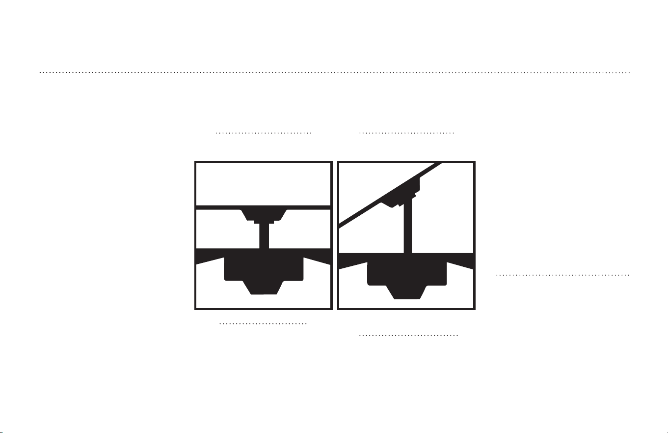
FEATURES
CARACTERÍSTICAS
VAULTED CEILING
INSTALLATION
INSTALACIÓN PARA
TECHOS INCLINADOS
DOWNROD
INSTALLATION
INSTALACIÓN CON
VARILLA VERTICAL
May require a longer downrod
(sold separately)
Podría requerir una varilla vertical
más larga
(se vende por separado)
For normal ceilings
Para techos normales
Note: For pitched ceiling installation,
please refer to westinghouselighting.
com for specially designed canopy
kit options.
Nota: Para instalación en techos
inclinados, visite westinghouselight-
ing.com para obtener opciones sobre
equipos de dosel especialmente
diseñados.
5
ETL-ES-Brentford-WH25
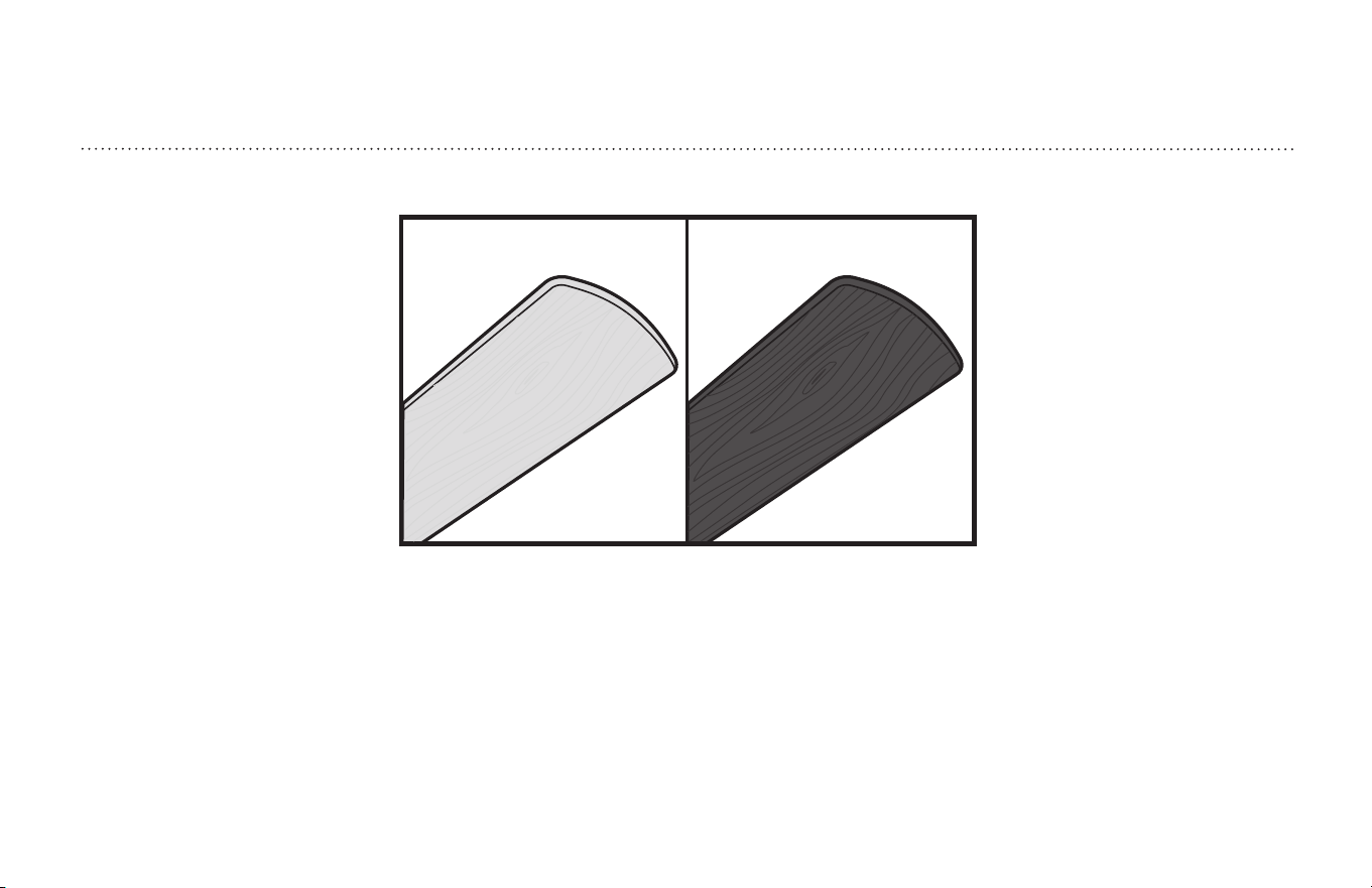
COMBO-BLADE
Combo-Blades feature two high quality finishes on one blade. Select the one that
best complements your decor, or change the style with just a flip of the blade.
NOTE: Combo-Blade finishes vary, depending upon model.
ALETAS DE DOBLE CARA
Las aletas de doble cara presentan dos superficies con un acabado de alta
calidad. Invirtiendo las aletas Ud. puede producir un efecto decorativo adaptado
a su ambiente o crear una decoración completamente nueva.
NOTA: las superficies de las aletas de doble cara son distintas dependiendo del modelo.
FEATURES
CARACTERÍSTICAS
6
ETL-ES-Brentford-WH25
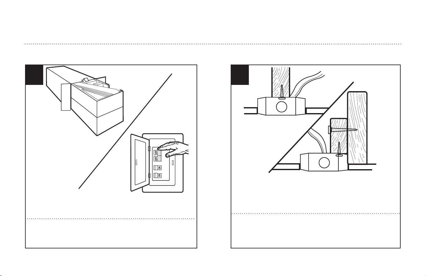
Unpack and inspect fan carefully to be certain all contents are included.
Turn off power at fuse box to avoid possible electrical shock.
1
Use metal outlet box suitable for fan support (must support 35 lbs).
Before attaching fan to outlet box, ensure the outlet box is securely
fastened by at least two points to a structural ceiling member (a loose
box will cause the fan to wobble).
2
PREPARING FOR INSTALLATION
ANTES DE LA INSTALACIÓN
Quite el envoltorio e inspeccione detenidamente el ventilador para veri-
ficar que todas las piezas estén incluidas. Apague la alimentación en la
caja de fusibles para evitar la posibilidad de descarga eléctrica.
Use una caja de embutir de metal adecuada para soportar un ventilador
(debe soportar 35 libras). Antes de fijar el ventilador a la caja de embutir
asegúrese de que la misma esté fijada de manera segura en por lo
menos dos puntos a un miembro estructural del techo (una caja suelta
haría que el ventilador oscile).
7
ETL-ES-Brentford-WH25
MOUNTING BRACKET INSTALLATION
INSTALACIÓN CON SOPORTE
DE MONTAJE
Instale el soporte de montaje (1) a la caja eléctrica del techo usando los tornillos
y arandelas suministrados con la caja eléctrica.
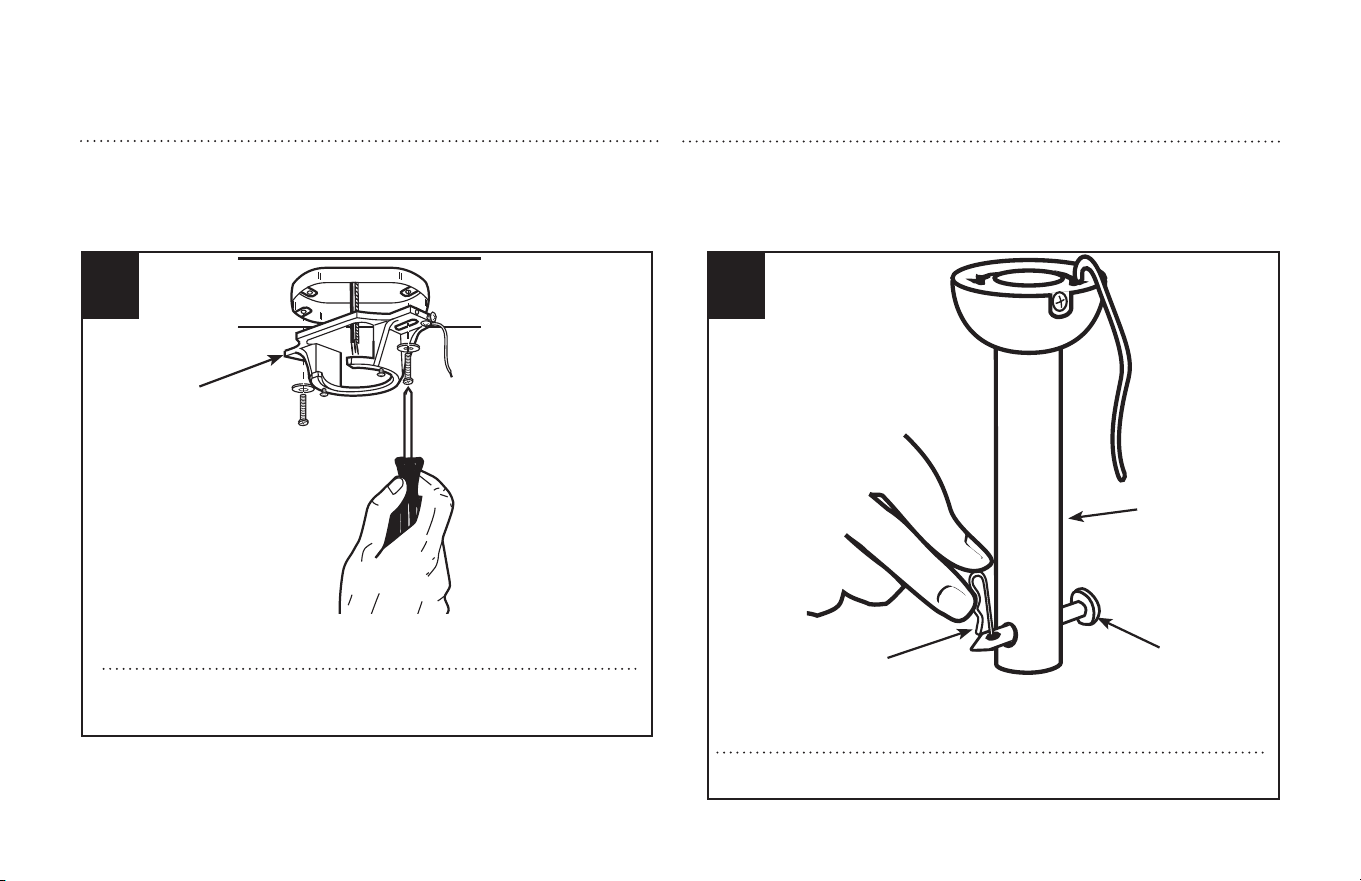
3
1
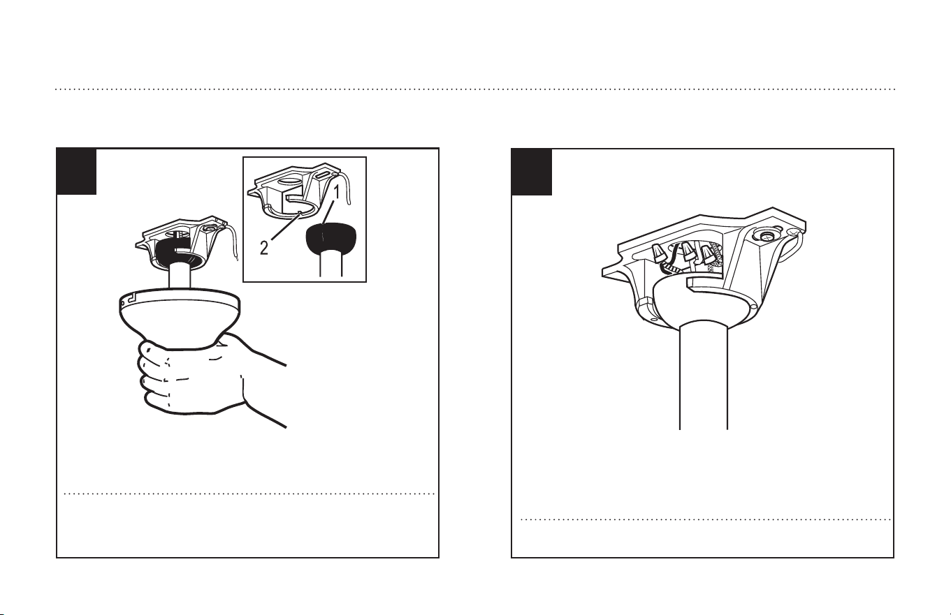
Install mounting bracket (1) to outlet box in ceiling using the screws and
washers provided with the outlet box.
Quite el pasador tipo prensa (1) desde el pasador transversal (2) de la vara (3).
4
Remove clamp pin (1) and cross pin (2) from downrod (3).
1
2
3
NORMAL DOWNROD OPTION
OPCIÓN CON VARILLA VERTICAL
PARA TECHO NORMAL
8
ETL-ES-Brentford-WH25
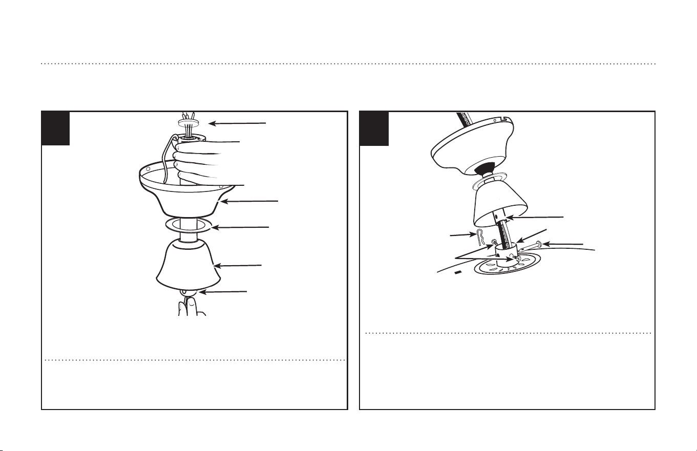
6
Place down rod assembly (4) into canopy (1), canopy cover ring (2) and coupling cover (3).
Feed motor wires through the down rod assembly (4). Insert the four wires from the fan
through the rubber down rod cover (5). This will prevent water from running through the
down rod.
Coloque el conjunto de la varilla vertical (4) dentro del dosel (1), el anillo de la cubierta del
dosel (2) y la cubierta del acoplamiento (3). Pase los cables del motor a través del conjunto
de la varilla vertical (4). Inserte los cuatro cables del ventilador a través de la cubierta de
goma de la varilla vertical (5). Esto evitará que el agua pase a través de la varilla vertical.
2
1
5
3
4
Loosen set screws (5) in downrod coupling (2). Insert downrod (1) into downrod
coupling (2). Make sure to align hole in downrod (1) with the hole in downrod cou-
pling (2). Install coupling cross pin (3) through coupling and downrod. Insert clamp
pin (4) into cross pin until it snaps into place. Tighten set screws (5) in coupling.
SEE APPENDIX FOR ALTERNATE INSTALLATION OPTIONSIN PAGE 19.
Afloje los tornillos prisioneros (5) en el acoplador (2). Inserte la vara (1) en el aco-
plador de vara (2). Asegúrese de alinear el agujero de la vara (1) con el agujero del
acoplador (2). Instale el pasador transversal del acoplador (3) a través del acop-
lador y la vara. Inserte el pasador tipo prensa (4) en el pasador transversal hasta
que trabe en su lugar. Apriete los tornillos prisioneros (5) en el acoplador.
CONSULTE
EL APÉNDICE PARA CONOCER LAS OPCIONES DE INSTALACIÓN ALTERNATIVAS EN LA
PAGINA 19.
NORMAL DOWNROD OPTION
OPCIÓN CON VARILLA VERTICAL PARA TECHO NORMAL
7
1
2
3
4
5
9
ETL-ES-Brentford-WH25
MOUNTING
MONTAJE
9
With bracket holding fan assembly, make electrical connections using the
following step for wiring instructions.
Con la pieza de montaje sujetando el conjunto del ventilador, haga las conex-
iones eléctricas de acuerdo a las siguientes instrucciones de cableado.
8
Carefully lift fan assembly onto mounting bracket. Rotate fan until notch
on downrod ball (1) engages the ridge on the mounting bracket (2). This
will allow for hands free wiring.
Levante con cuidado el conjunto del ventilador hasta el soporte de mon-
taje. Gire el ventilador hasta que la muesca de la bola de la varilla vertical
(1) calce sobre la saliente del soporte de montaje (2). De este modo, ten-
drá las dos manos libres para hacer el cableado.
10
ETL-ES-Brentford-WH25
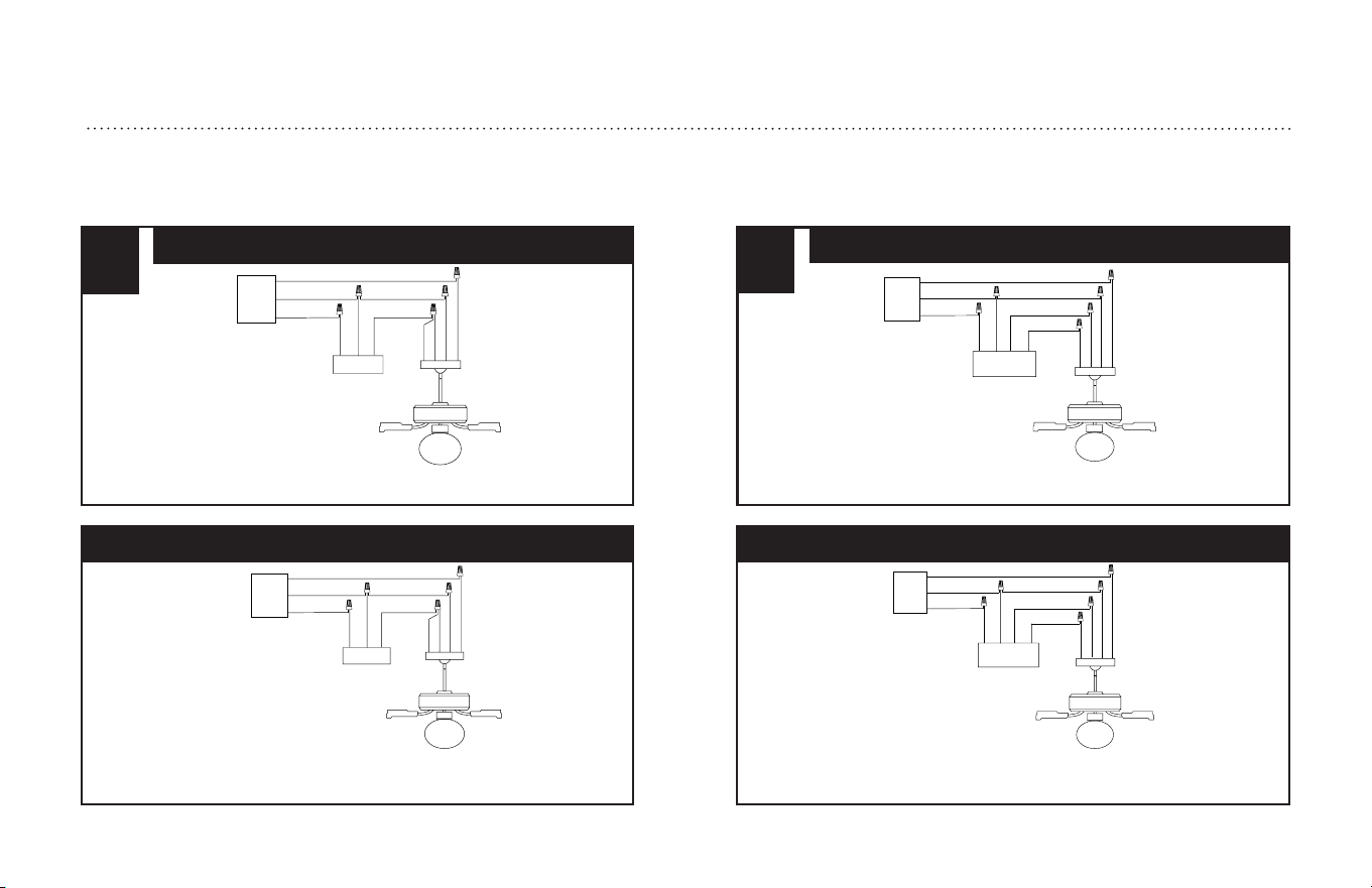
WIRING OPTIONS
OPCIÓN DE CABLEADO
Siga las instrucciones del diagrama anterior para hacer las conexiones de
cableado para el ventilador con control de pared.
Siga las instrucciones del diagrama anterior para hacer las conexiones de
cableado para el ventilador controlado con cadenilla de tiro.
11
Blue (hot)
Green Ground
White (neutral)
Black (hot)
AC IN L
AC IN N
Green Ground
To Light L
Blue
Black
AC IN L
Green Ground
Wall
Control
AC
Power
Supply
To Motor L
Black
10
AC IN L
AC IN N
Green Ground
To Motor
Black (hot)
Blue (hot)
Green Ground
White (neutral)
Black
Black
AC IN L
Green Ground
Wall Switch
AC
Power
Supply
PULL CHAIN WIRING OPTION
WALL CONTROL WIRING OPTION
Azul (vivo)
Verde (de tierra)
Blanco (neutro)
Entrada C.A. L
Entrada C.A. N
Verde (de tierra)
A la Luz L
Azul
Negro
Entrada C.A. L
Verde (de tierra)
Control de
Pared
Fuente de
alimentación
de CA
Al Motor L
Negro
Negro (vivo)
Entrada C.A. L
Entrada C.A. N
Verde (de tierra)
Al Motor
Negro (vivo)
Azul (vivo)
Verde (de tierra)
Blanco (neutro)
Negro
Negro
Entrada C.A. L
Verde (de tierra)
Interruptor
de Pared
Fuente de
alimentación
de CA
OPCIÓN DE CABLEADO PARA CADENILLA DE TIRO
OPCIÓN DE CABLEADO PARA CONTROL DE PARED
Follow diagram above to make wiring connections for fan pull chain
control.
Follow diagram above to make wiring connections for wall control
operation.
11
ETL-ES-Brentford-WH25
SECURE TO CEILING
ASEGURE EL VENTILADOR AL TECHO
12
1
2
3
2
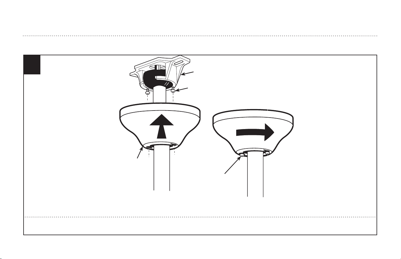
Align the keyholes on the canopy (3) with the protruding screw heads (2) from the mounting bracket (1). Lift the canopy up and rotate clockwise until the screw-
heads engage the keyslots fully.
Alinee los agujeros del escudete (3) con las cabezas de tornillo sobresalientes (2) del soporte de montaje (1). Levante el escudete y gírelo en dirección de las mane-
cillas del reloj hasta que las cabezas de tornillo calcen por completo con los chaveteros.
12
ETL-ES-Brentford-WH25
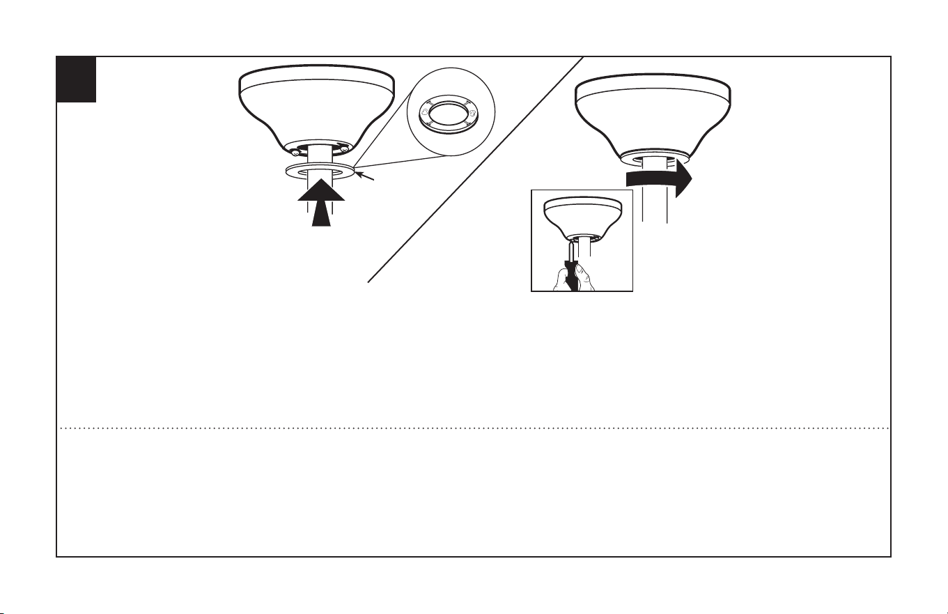
The inside canopy cover ring (1) has two keyhole slots that allow it to be mounted onto the screw heads on the two protruding screws from the mounting bracket.
Slide the canopy cover ring up the downrod, and allow the two protruding screw heads from the mounting bracket to go into the keyhole slots on the canopy cover
ring. Once engaged, twist the canopy cover ring to lock it onto the screw heads.
Note: Some adjustment of the screws from the mounting bracket may be necessary to allow the canopy cover ring to attach to the screw heads in the appropriate
manner:
1. Loosening of the screw heads may be necessary to allow the canopy cover ring to fit onto the screws from the mounting bracket.
2. If the canopy is still loose after installing the canopy cover ring, the canopy cover ring may need to be removed and the mounting bracket screws tightened slightly
to allow a more snug fit of the canopy, when the canopy cover ring is installed.
La cubierta interior para el anillo (1) del dosel tiene dos ranuras que permiten montarla en las cabezas de los dos tornillos que sobresalen del soporte de montaje.
Deslice la cubierta el anillo del escudete hacia arriba por la varilla y permita que las dos cabezas sobresalientes de los tornillos penetren en las ranuras de la cubierta
del escudete. Una vez penentren, gire la cubierta del escudete para trabar las cabezasde los tornillos en la parte más estrecha.
Nota: Puede ser necesario ajustar los tornillos del soporte de montaje para permitir que la cubierta del escudete se acople a las cabezas de los tornillos de manera
apropiada.
1. Afloje los tornillos si es necesario para permitir que la cubierta del escudete pase sobre los tornillos del soporte de montaje.
2. Si el escudete aún está suelto después de instalar la cubierta el anillo del escudete, puede que sea necesario retirar la cubierta el anillo del escudete y apretar l
igeramente los tornillos del soporte de montaje para lograr un ajuste más preciso del escudete una vez instalada la cubierta el anillo del escudete.
13
1
13
ETL-ES-Brentford-WH25
BLADE INSTALLATION
INSTALACIÓN DE LAS ALETAS
14 15
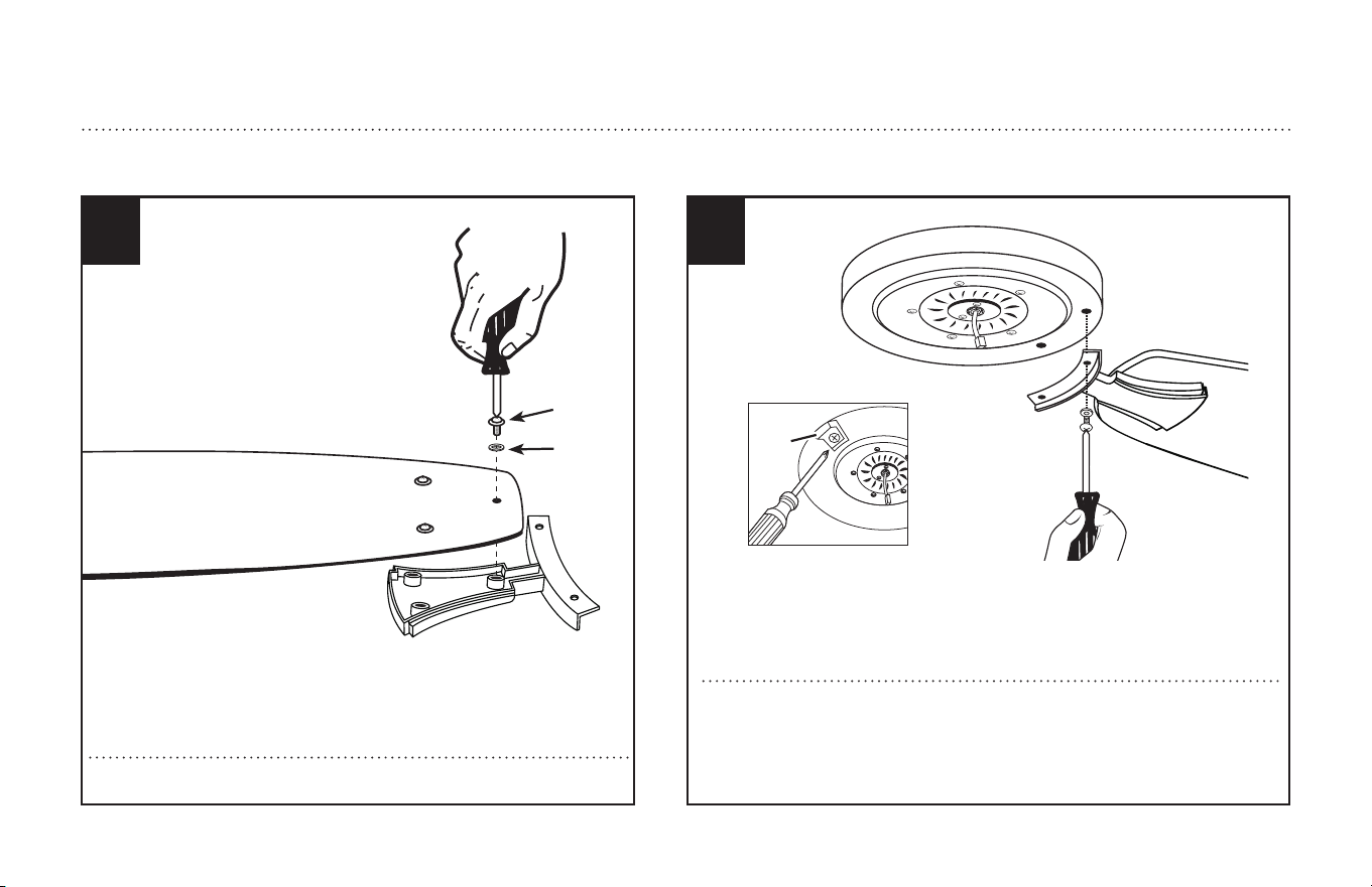
Attach blade brackets to blades using the blade screws (1) and washers (2).
Fije los soportes para aletas a las aletas con (1) y las arandelas (2).
Check the motor for plastic shipping stabilizer tabs (1), and remove them if they
are present. Attach blade assembly to motor using motor screws provided.
Tighten screws securely. NOTE: Some models do not utilize motor gaskets,
washers, or stabilizer tabs.
Revise el motor buscando las lengüetas plásticas estabilizadoras (1) que se
colocan para el embalaje y retírelas si las hay. Fije el conjunto de las aletas al
motor usando los tornillos para el motor incluidos. Apriete los tornillos ase-
gurándolos. NOTA: Algunos modelos no utilizan juntas para el motor, arandelas
o lengüetas de embalaje.
1
2
1
14
ETL-ES-Brentford-WH25
LIGHT FIXTURE INSTALLATION
INSTALACIÓN DEL ARTEFACTO LUMINOSO
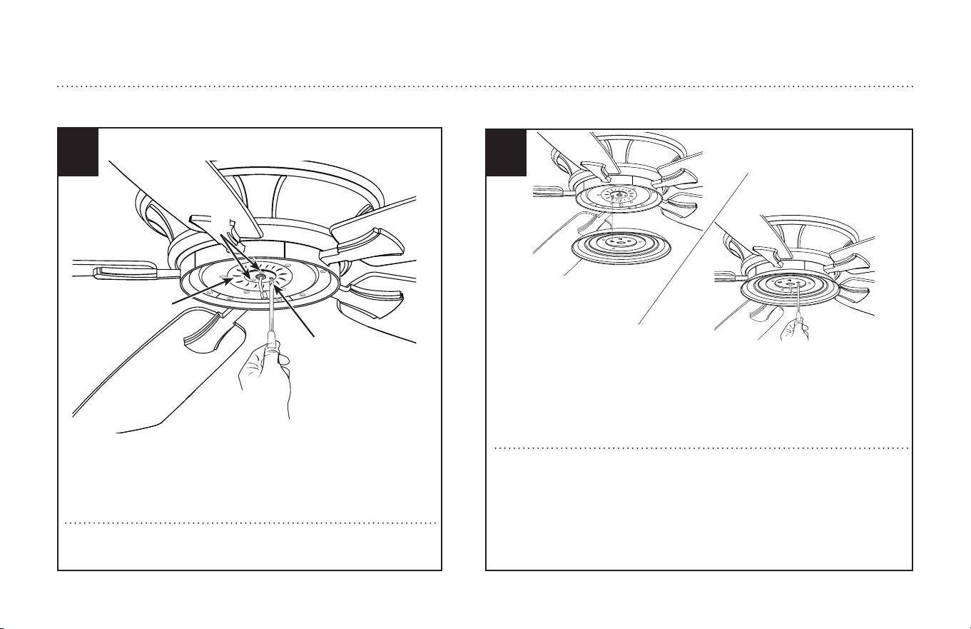
Insert the wires from motor through the center hole in the switch housing.
Attach the switch housing onto the mounting plate, by placing the key slot holes
from the switch housing onto the two protruding screw heads from the mount-
ing plate. Twist the switch housing clockwise until the screw heads engage
the key slots. Install the screw removed from mounting plate (step 16) into the
closed hole in the switch housing. Tighten all screws to complete assembly of
the switch housing.
Pase los cables del motor a través del agujero central del alojamiento del interrup-
tor. Fije el alojamiento del interruptor a la placa de montaje colocando las ranuras
del alojamiento del interruptor sobre las dos cabezas de los tonillos que sobresalen
de la placa de montaje. Gire el alojamiento del interruptor en sentido horario hasta
que las cabezas de los tornillos enganchen en las ranuras. Coloque el tornillo que
extrajo de la placa de montaje (paso 16) en el agujero cerrado del alojamiento del
interruptor. Ajuste todos los tornillos para completar la instalación del alojamiento
del interruptor.
16
Remove one of the screws (1) on the mounting plate (3), and loosen, (do
not remove) the other two (2).
Quite uno de los tornillos (1) del soporte de la placa del juego de luz (3) y
suelte (sin quitar) los otros dos (2).
17
2
3
1
15
ETL-ES-Brentford-WH25
19
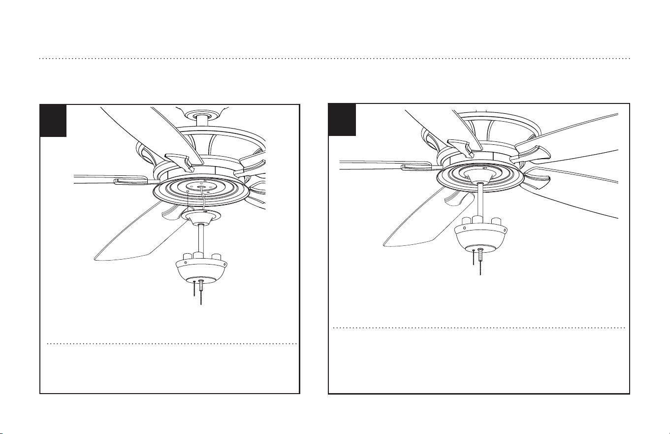
Attach the light kit to the switch housing by placing the keyslot holes from the
light kit onto the two protruding screw heads from the switch housing. Twist the
light kit until the screwheads engage the keyslots. Install the screw removed from
the switch housing (step 18) into the closed hole in the light kit. Tighten all screws
to complete attachment of the light kit.
Fije el juego de luces al alojamiento del interruptor colocando las ranuras del juego
de luz sobre las dos cabezas de los tornillos que sobresalen del alojamiento del
interruptor. Gire el juego de luz hasta que las cabezas de los tornillos enganchen
en las ranuras. Coloque el tornillo que extrajo del alojamiento del interruptor (paso
18) en el agujero cerrado del juego de luz. Ajuste todos los tornillos para completar
la instalación del juego de luz.
Remove one of the screws on the switch housing, and loosen (do not
remove) the other two. Connect the wires in switch housing to the
wires from the light kit, using the 4-pin molex plug.
Quite uno de los tornillos del alojamiento del interruptor y afloje los
otros dos (sin sacarlos del todo). Conecte los cables del alojamiento
del interruptor a los cables del juego de luz utilizando el conector
Molex de 4 pines.
18
LIGHT FIXTURE INSTALLATION
INSTALACIÓN DEL ARTEFACTO LUMINOSO
16
ETL-ES-Brentford-WH25
1
2
3
21
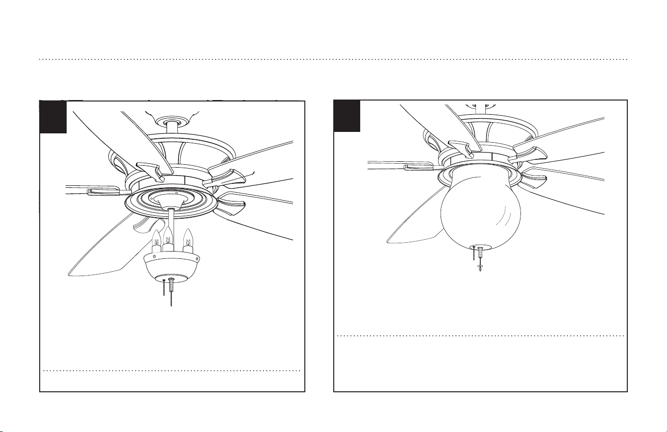
While holding the glass, slide the fan pull chain through the side hole of glass and let
the light kit pull chain through the center hole of glass. Lift the glass up to the light kit,
allowing the threaded rod to go through the center hole in the bottom of the glass. Install
the rubber washer, metal washer and nut onto bottom of the glass. Tighten the nut to
the glass.
Sosteniendo el vidrio, pase la cadenilla de tiro del ventilador por el agujero lateral del
vidrio y permita que la cadenilla de tiro del juego de luces pase por el agujero central del
vidrio. Levante el vidrio hasta el juego de luces, permitiendo que la varilla roscada pase
por el agujero central de la parte inferior del vidrio. Coloque la arandela de caucho, la
arandela de metal y la tuerca en la parte inferior del vidrio. Ajuste la tuerca al vidrio.
Install light bulbs (included).
Instale las bombillas de luz (incluidas).
20
LIGHT FIXTURE INSTALLATION
INSTALACIÓN DEL ARTEFACTO LUMINOSO
17
ETL-ES-Brentford-WH25
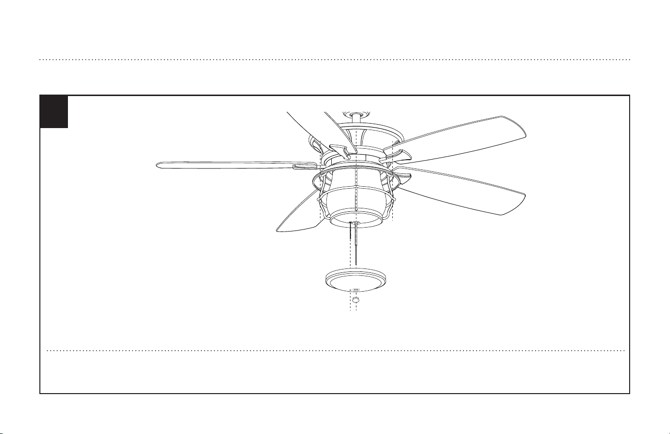
Lift the metal frame and the metal cap up to the glass and slide the fan pull chain through the side hole of the metal cap and let the light kit pull chain through the
center hole of the metal cap. Thread the light kit pull chain through the finial and tighten the finial to fix the metal frame and metal cap securely.
Levante el armazón y la tapa de metal hasta el vidrio y pase la cadenilla de tiro del ventilador por el agujero lateral de la tapa de metal, mientras permite que la cad-
enilla de tiro del juego de luz pase por el agujero central de la tapa. Enrosque la cadenilla de tiro del juego de luz a través del florón y ajuste el florón para asegurar el
armazón y la tapa de metal.
22
LIGHT FIXTURE INSTALLATION
INSTALACIÓN DEL ARTEFACTO LUMINOSO
18
ETL-ES-Brentford-WH25
23
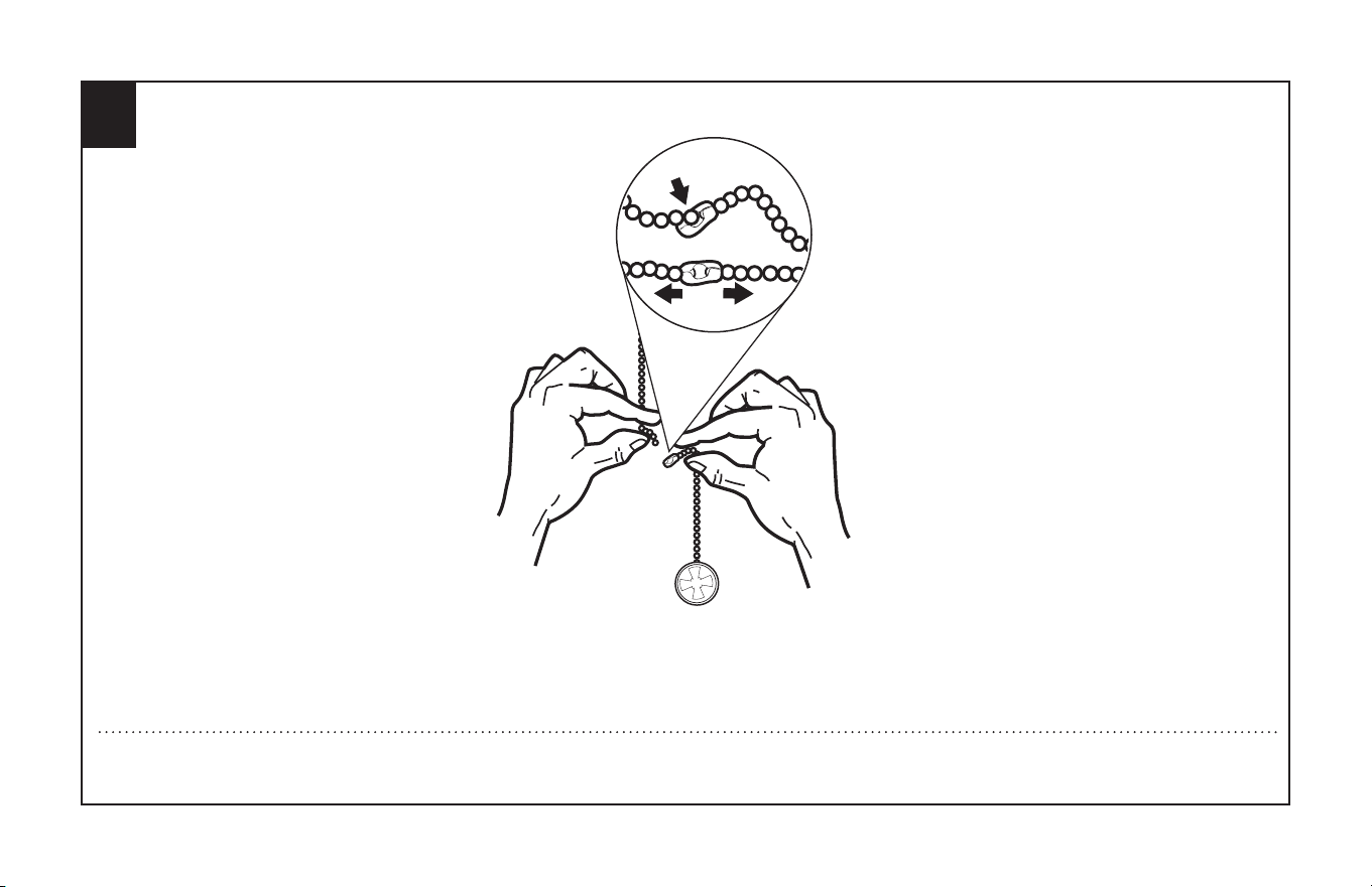
Assemble decorative fob and extension chains (L) from hardware bag to fan pull chains by inserting end of chain into chain coupling. Confirm chains are held by
lightly pulling both chains in coupling.
Sujetar las cadenas largas de tiro con las piezas finales (L) correspondientes, a las cadenas del ventilador, introduciendo el extremo de la cadena larga en la pieza
de unión. Asegúrese de que las cadenas están bien sujetas, tirando ligeramente de ambas cadenas en la pieza de unión.

19
ETL-ES-Brentford-WH25
Appendix for alternate installation options
EXTENDED DOWNROD OPTION (from page# 20 to #21)
Apéndice para opciones de instalación alternativas
OPCIÓN CON VARILLA VERTICAL MÁS LARGA (desde la página # 20 a la página # 21)
20
ETL-ES-Brentford-WH25
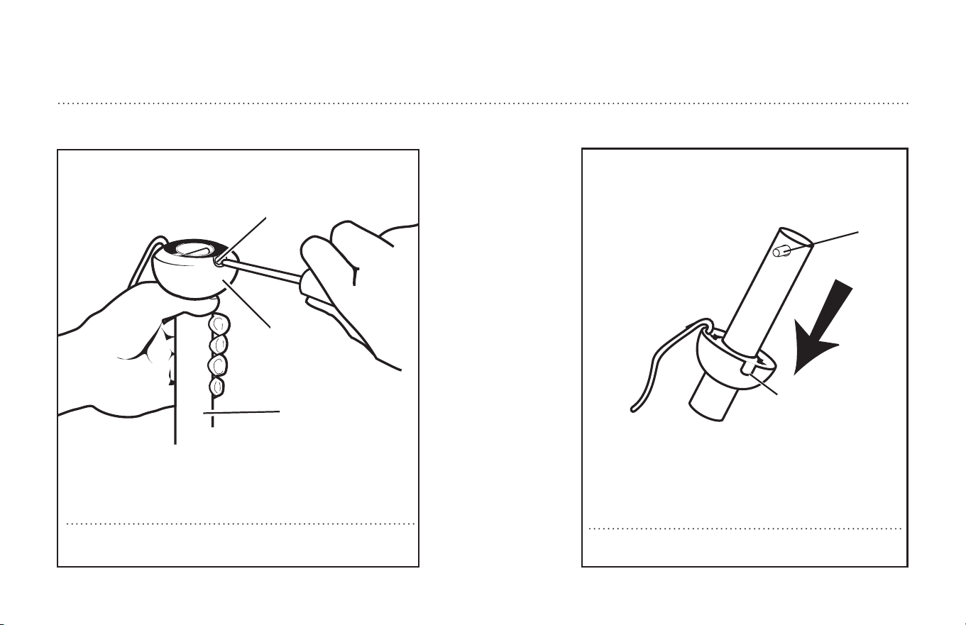
Slide downrod ball (1) off of downrod and remove pin (2).
Deslice la bola de la varilla vertical (1) hasta separarla de la varilla
vertical y quite el pasador (2).
2
1
Loosen downrod ball (1) from downrod (2) by removing set screw (3).
Afloje la bola de la varilla vertical (1) de la varilla vertical (2)
quitando el tornillo (3).
2
3
1
EXTENDED DOWNROD OPTION
OPCIÓN CON VARILLA VERTICAL MÁS LARGA
21
ETL-ES-Brentford-WH25
EXTENDED DOWNROD OPTION
OPCIÓN CON VARILLA VERTICAL MÁS LARGA
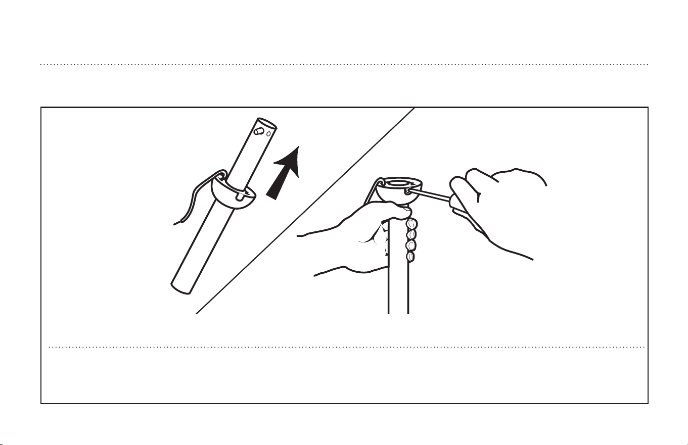
Re-install pin into extended downrod, and slide downrod ball up to the top of the downrod. Re-install set screw to secure ball to downrod. Note: Some extended
downrods have a pre-drilled set-screw hole. If a pre-drilled hole is present in the extended downrod, tighten the set screw into the pre-drilled hole in the extended
downrod. If no pre-drilled hole exists in the extended downrod, tighten the set screw against the downrod to secure the downrod ball. Process to Page #8 Step 6.
Vuelva a instalar el pasador en la varilla vertical más larga y deslice la bola de la varilla hasta el extremo superior de la misma. Vuelva a insertar el tornillo de fija-
ción para asegurar la bola a la varilla vertical. Nota: Algunas varillas verticales más largas tienen un agujero previamente perforado para el tornillo. Si la varilla verti-
cal más larga tiene un agujero previamente perforado, ajuste el tornillo en el agujero previamente perforado de la varilla vertical más larga. Si la varilla vertical más
larga no tiene un agujero previamente perforado, ajuste el tornillo sobre la varilla vertical para asegurar la bola de la misma. PROCEDA A LA PÁG. #8, PASO 6.
22
ETL-ES-Brentford-WH25
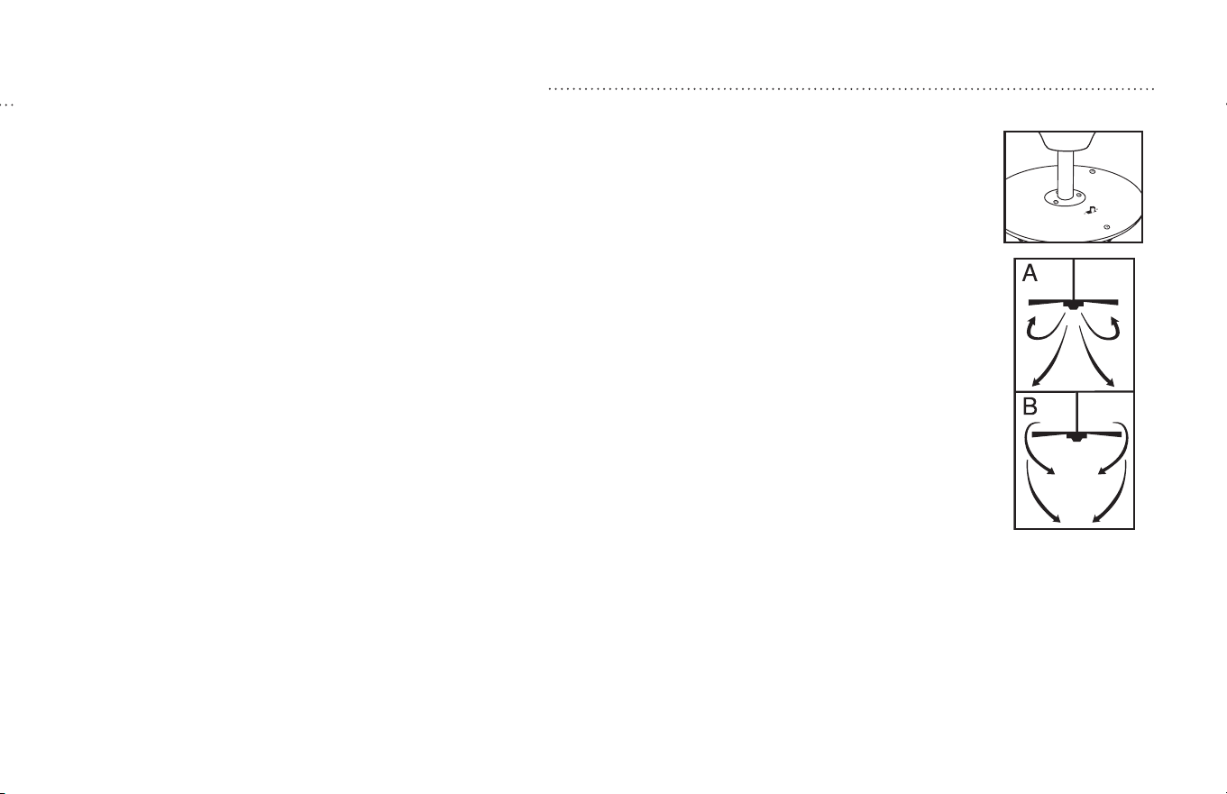
Operation
Turn on the power and check operation of fan. The pull chain controls the fan speeds as follows: 1 pull - high; 2 pulls - medium; 3 pulls - low;
4 pulls - off. Speed settings for warm or cool weather depend on factors such as room size, ceiling height, number of fans and so on.
The slide switch controls direction, forward or reverse.
Warm weather - (Forward) Fan turns counterclockwise direction. A downward air flow creates a cooling effect.
This allows you to set your air conditioner on a higher temperature setting without affecting your comfort.
Cool weather - (Reverse) Fan turns clockwise direction. An upward airflow moves warm air off the ceiling area.
This allows you to set your heating unit on a lower setting without affecting your comfort.
(Please however refer to point 14 in Safety Tips when operating in this position.)
NOTE: Turn off and wait for fan to stop before changing the setting of the forward/reverse slide switch
Maintenance
1. Because of the fan’s natural movement, some connections may become loose. Check the support connections, brackets, and blade
attachments twice a year. Make sure they are secure.
2. Clean your fan periodically to help maintain its new appearance over the years. Do not use water when cleaning.
This could damage the motor, or the wood, or possibly cause electrical shock.
3. Use only a soft brush or lint-free cloth to avoid scratching the finish. The plating is sealed with a lacquer coating to minimize
discoloration or tarnishing.
4. There is no need to oil your fan. The motor has permanently lubricated bearings.
OPERATION AND MAINTENANCE
23
ETL-ES-Brentford-WH25
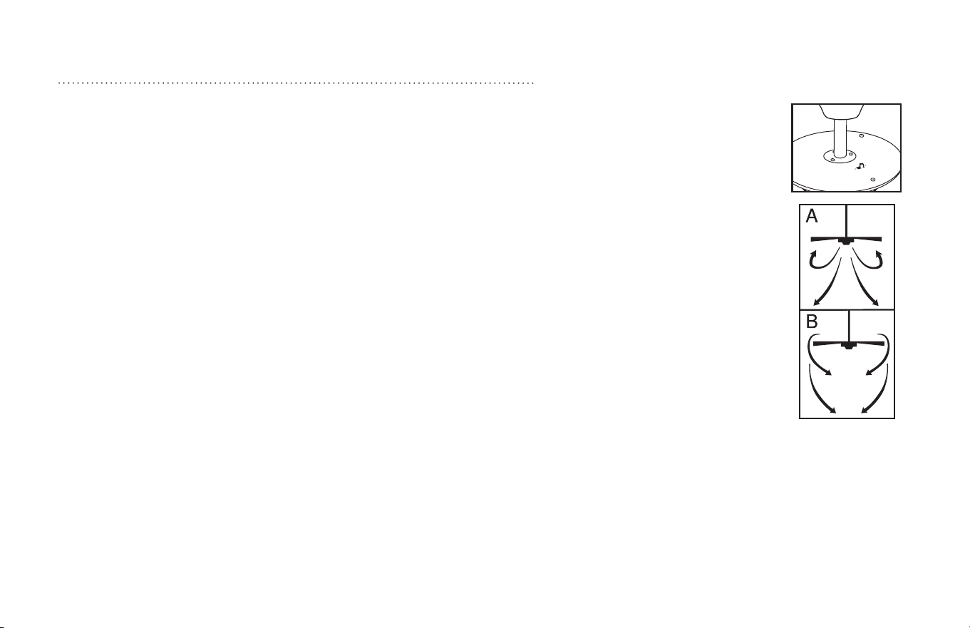
Operación
Encienda el ventilador y verifique su funcionamiento. La cadenilla de tiro controla las velocidades del ventilador de la siguiente manera:
1 tirón – rápida; 2 tirones – mediana; 3 tirones – lenta; 4 tirones – apagado.
Las velocidades para clima cálido o frío dependen de factores como el tamaño de la habitación, la altura del techo, el número de \ ventiladores y otros.
El interruptor deslizante controla la dirección, hacia adelante o hacia atrás. Clima cálido – (hacia adelante) El ventilador gira en el sentido con-
trario al reloj. El flujo de aire hacia abajo crea un efecto refrescante. Esto le permite ajustar su acondicionador de aire a una temperatura más
alta sin afectar su comodidad.Clima frío – (hacia atrás) El ventilador gira en el sentido del reloj. El flujo de aire hacia arriba circula el aire caliente
que se acumula en el área del techo. Esto le permite ajustar su unidad de calefacción a una temperatura más baja sin afectar su comodidad.
(De todos modos, refiérase por favor al punto 14 de la información sobre seguridad cuando utilice el ventilador en esta posición).
NOTA: Apague el ventilador y espere a que se detenga antes de cambiar la dirección hacia adelante/atrás con el interruptor deslizante.
Mantenimiento
1. El movimiento natural del ventilador podría hacer que se aflojen algunas conexiones. Verifique las conexiones de soporte, las piezas de
fijación y los accesorios de las aletas dos veces al año. Cerciórese de que estén aseguradas.
2. Limpie el ventilador periódicamente para ayudar a mantener su apariencia nueva con el correr de los años. No use agua para limpiarlo, ya
que podría dañar el motor o la madera o causar descarga eléctrica.
3. Use sólo un cepillo blando o un trapo sin pelusa para no rayar el acabado. El enchapado está sellado con una capa de laca para minimizar la
decoloración o pérdida del brillo.
4. No hay necesidad de aceitar el ventilador. El motor tiene cojinetes de lubricación permanente.
OPERACIÓN Y MANTENIMIENTO

24
ETL-ES-Brentford-WH25
TROUBLESHOOTING
GUIDE
If you have difficulty operating your new ceiling fan, it may be the result of incorrect assembly, installation, or
wiring. In some cases, these installation errors may be mistaken for defects. If you experience any faults,
please check this Trouble Shooting Chart. If a problem cannot be remedied, please consult with your qualified
electrician and do not attempt any electrical repairs yourself.
TROUBLE SUGGESTED REMEDY
1. If fan does not start: 1. check main and branch circuit fuses or circuit breakers.
2. check wire connections as performed in step #10 or #11 of installation.
CAUTION: Make sure main power is turned off.
3. Make sure forward/reverse switch is firmly in up or down position.
Fan will not operate when switch is in the middle.
4. If the fan still will not start, contact a qualified electrician.
Do not attempt to troubleshoot internal electrical connections yourself.
2. If fan sounds noisy: 1. check to make sure all screws in motor housing are snug (not over tightened).
2. check to make sure the screws which attach the fan blade holder to the motor are tight.
3. Some fan motors are sensitive to signals from Solid State variable speed controls.
DO NOT USe a Solid State variable speed control.
4. Allow “break-in” period of 24 hours. Most noises associated with a new fan will disappear after this period.
3. If fan wobbles: All blades are weighed and grouped by weight. Natural woods vary in density which could cause the fan to wobble even though all blades
are weight-matched. The following procedures should eliminate most of the wobble. check for wobble after each step.
1. check that all blades are screwed firmly into blade holders.
2. check that all blade holders are tightened securely to motor.
3. Make sure that canopy and mounting bracket are tightened securely to ceiling joist.
4. If blade wobble is still noticeable, interchanging two adjacent (side by side) blades can redistribute the weight and possibly result in
smoother operation.
4. If light does not work: 1. check to see that the wire connections in the switch housing are connected.
2. check for faulty light bulbs.
3. If light kit will still not operate, contact a qualified electrician for assistance.

25
ETL-ES-Brentford-WH25
GUÍA PARA SOLUCIONAR
PROBLEMAS
Si tiene dificultades para hacer funcionar su nuevo ventilador, podría ser a causa del armado,
instalación o cableado incorrectos. En algunos casos, estos errores de instalación podrían
ser confundidos con defectos. Si experiencia algun fallo, consulte esta guía para solucionar
problemas. Si no puede solucionar el problema, consulte a un electricista calificado y no
intente reparar conexiones eléctricas.
PROBLEMA
1. Si el ventilador no
arranca:
2. Si el ventilador es
ruidoso:
3. Si el ventilador oscila:
4. Si la luz no funciona:
SOLUCIÓN SUGERIDA
1. Compruebe los fusibles o disyuntores principales y del circuito derivado.
2.Compruebe el cableado del bloque de terminales como lo hizo en el paso No. 10 ó 11 de la instalación.
ADVERTENCIA: Asegúrese de que la alimentación principal esté apagada.
3. Asegúrese de que el interruptor de marcha adelante/atrás esté firmemente en su posición.
El ventilador no funcionará si el interruptor está en el medio.
4.Si el ventilador no arranca, póngase en contacto con un electricista calificado. No intente reparar conexiones eléctricas internas.
1. Compruebe para asegurarse de que todos los tornillos del alojamiento del motor estén ajustados (no los apriete demasiado).
2.Compruebe para asegurarse de que los tornillos que fijan el soporte de la aleta del ventilador al motor estén apretados.
3. NO USE un control de velocidad variable de estado sólido.
4.Permita el "rodaje" del ventilador durante un período de 24 horas. La mayoría de los ruidos asociados con el ventilador nuevo desaparecerán
después de este período.
Todas las aletas se pesan y agrupan según el peso. Las maderas naturales varían en densidad y podrían hacer que el ventilador oscile aún cuando
todas las aletas estén agrupadas por peso. Los siguientes procedimientos deberían eliminar la mayoría de los problemas de oscilación. Verifique la
oscilación después de cada paso.
1. Verifique que todas las aletas estén firmemente atornilladas a los soportes de las aletas.
2.Verifique que todos los soportes de las aletas estén firmemente aseguradas al motor.
3. Asegúrese de que el dosel y el soporte de montaje estén firmemente asegurados a la viga del techo.
4.Si la oscilación de la aleta sigue siendo visible, es posible que al intercambiar dos aletas adyacentes (lado a lado) se redistribuya el peso y el
funcionamiento sea más suave.
1. Verifique que el conector molex del alojamiento del interruptor esté conectado.
2. Compruebe si hay lámparas defectuosas.
3. Si el conjunto de luces no funciona, póngase en contacto con un electricista calificado.

26
ETL-ES-Brentford-WH25
WARRANTY
This Westinghouse Lighting Fan offers a Limited Lifetime Warranty to the original owner against defects in material and workmanship.
This warranty is in lieu of all other warranties expressed or implied.
Westinghouse Lighting will repair or replace the parts needed, and/or, replace the ceiling fan, if the defective is due to faulty materials or workmanship.
Years 1 & 2 – Westinghouse Lighting will repair or replace this ceiling fan.
After Year 2 – Warranty is limited to the motor.
This warranty does not cover acts of nature such as lightning damage, or corrosion and discoloration of components, nor does it cover damages caused through
abuse, improper installation, surges in electric current, or acts of third parties. This warranty does not cover broken glass after installation. If this ceiling fan fails
during the warranty period, return defective product to seller. Warranty terms and conditions of sellerr apply. If replacement product is not available through seller,
please contact www.westinghouselighting.com/contact-us.
GARANTÍA
Este ventilador de Westinghouse Lighting se ofrece con una garantía limitada de por vida para el propietario original frente a defectos de material y de mano de obra.
Esta garantía sustituye cualquier otra garantía expresa o implícita.
Westinghouse Lighting reparará o reemplazará las piezas necesarias y/o reemplazará el ventilador de techo si el fallo se debe a defectos de material o de mano de
obra.
Primeros 2 años: Westinghouse Lighting reparará o reemplazará este ventilador de techo.
Después del segundo año: la garantía queda limitada al motor.
Esta garantía no cubre los daños debidos a fenómenos naturales, como daños por caída de rayos, corrosión o decoloración de los componentes, ni tampoco los daños
causados por un uso inadecuado, una instalación incorrecta, sobretensiones eléctricas o actos de terceros. Esta garantía no cubre la rotura de vidrio una vez que se
haya realizado la instalación. Si el ventilador de techo falla durante el período de garantía, devuelva el producto defectuoso al distribuidor. Se aplican los términos y
condiciones de garantía del vendedor. Si el producto de reemplazo no está disponible por medio del distribuidor, póngase en contacto con nosotros a través de www.
westinghouselighting.com/contact-us.
27
ETL-ES-Brentford-WH25
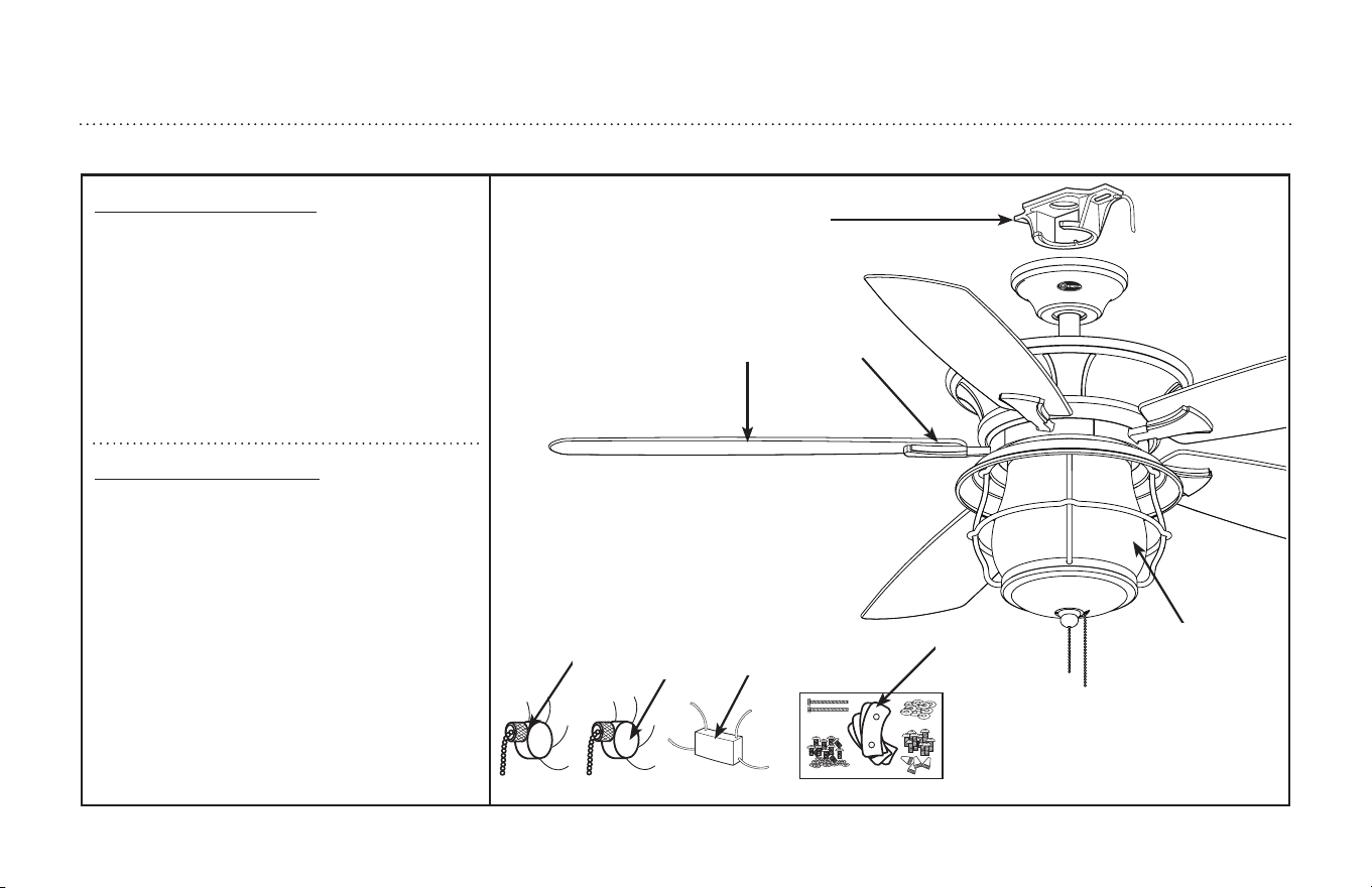
PARTS LIST
LISTA DE REPUESTOS
8
7
5
6
2
3
4
1
# . . . . . . . . . . . Description
1 . . . . . . . . . . . Mounting Bracket (1)
2 . . . . . . . . . . . Blade Bracket (5)
3 . . . . . . . . . . . Blade (5)
4 . . . . . . . . . . . Glass (1)
5 . . . . . . . . . . . Fan Speed Switch (1)
6 . . . . . . . . . . . Light Control Switch (1)
7 . . . . . . . . . . . Capacitor (2)
8 . . . . . . . . . . . Hardware Pack (1)
No. . . . . . . . . . . . Descripción
1 . . . . . . . . . . . Soporte de montaje (1)
2 . . . . . . . . . . . Soporte de aleta (5)
3 . . . . . . . . . . . Aleta (5)
4 . . . . . . . . . . . Pantalla de vidrio (1)
5 . . . . . . . . . . . Interruptor de control de
. . . . . . . . . . . velocidad para ventilador (1)
6 . . . . . . . . . . .
Interruptor de control de luz (1)
7 . . . . . . . . . . . Condensador (2)
8 . . . . . . . . . . . Tornillería (1)

ETL-ES-Brentford-WH25
and Westinghouse are trademarks of
Westinghouse Electric Corporation.
Used under license by Westinghouse Lighting.
All Rights Reserved.
Made in China
Westinghouse Lighting, Philadelphia, PA 19154-1029, U.S.A.
www.westinghouselighting.com