Visit our website at: https://www.harborfreight.com
email our technical support at: [email protected]
221531E-B
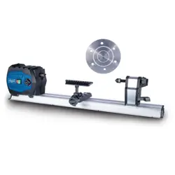
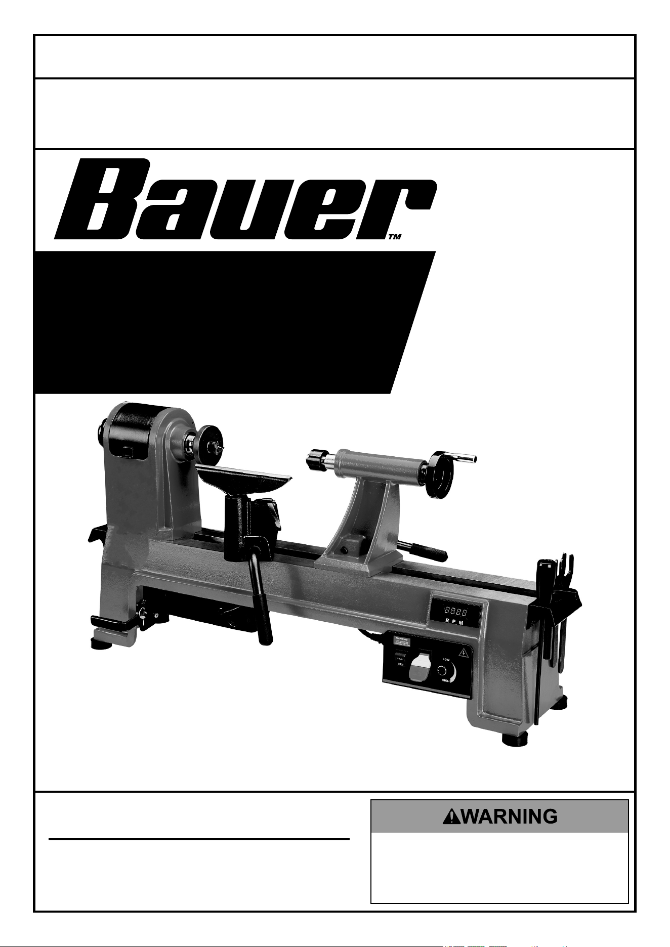
14" X 20"
EVS WOOD
MIDI-LATHE
59583
Owner’s Manual & Safety Instructions
Save This Manual Keep this manual for the safety warnings and precautions, assembly,
operating, inspection, maintenance and cleaning procedures. Write the product’s serial number in the
back of the manual near the assembly diagram (or month and year of purchase if product has no number).
Keep this manual and the receipt in a safe and dry place for future reference. 24k
When unpacking, make sure that the product is intact
and undamaged. If any parts are missing or broken,
please call 1-800-444-3353 as soon as possible.
Copyright
©
2022 by Harbor Freight Tools
®
. All rights reserved.
No portion of this manual or any artwork contained herein may be reproduced in
any shape or form without the express written consent of Harbor Freight Tools.
Diagrams within this manual may not be drawn proportionally. Due to continuing
improvements, actual product may differ slightly from the product described herein.
Tools required for assembly and service may not be included.
read this material before using this product.
Failure to do so can result in serious injury.
SaVe tHiS ManuaL.

Page 2 For technical questions, please call 1-800-444-3353. Item 59583
SaFety OperatiOn MaintenanceSetup
table of contents
Safety ......................................................... 2
Specifications ............................................. 6
Setup .......................................................... 6
Operation .................................................... 8
Maintenance .............................................. 14
Parts List and Diagram .............................. 16
Warranty .................................................... 19
WarninG SyMBOLS anD DeFinitiOnS
This is the safety alert symbol. It is used to alert you to potential
personal injury hazards. Obey all safety messages that
follow this symbol to avoid possible injury or death.
Indicates a hazardous situation which, if not avoided,
will result in death or serious injury.
Indicates a hazardous situation which, if not avoided,
could result in death or serious injury.
Indicates a hazardous situation which, if not avoided,
could result in minor or moderate injury.
Addresses practices not related to personal injury.
iMpOrtant SaFety inFOrMatiOn
General tool Safety Warnings
read all safety warnings and instructions.
Failure to follow the warnings and instructions may result in electric shock, fire and/or serious injury.
Save all warnings and instructions for future reference.
1. KEEP GUARDS IN PLACE and in working order.
2. REMOVE ADJUSTING KEYS AND
WRENCHES. Form habit of checking to
see that keys and adjusting wrenches are
removed from tool before turning it on.
3. KEEP WORK AREA CLEAN.
Cluttered areas and benches invite accidents.
4. DON’T USE IN DANGEROUS ENVIRONMENT.
Don’t use power tools in damp or wet locations,
or expose them to rain. Keep work area well lighted.
5. KEEP CHILDREN AWAY. All visitors should
be kept safe distance from work area.
6. MAKE WORKSHOP KID PROOF with padlocks,
master switches, or by removing starter keys.
7. DON’T FORCE TOOL. It will do the job better
and safer at the rate for which it was designed.
8. USE RIGHT TOOL. Don’t force tool or attachment
to do a job for which it was not designed.

Page 3For technical questions, please call 1-800-444-3353.Item 59583
SaFetyOperatiOnMaintenance Setup
table a: recOMMenDeD MiniMuM Wire GauGe
FOr eXtenSiOn cOrDS
(120 VOLt)
naMepLate
aMpereS
(at full load)
eXtenSiOn cOrD
LenGtH
25′ 50′ 100′ 150′
0 – 6 18 16 16 14
6.1 – 10 18 16 14 12
10.1 – 12 16 16 14 12
12.1 – 16 14 12 Do not use.
9. USE PROPER EXTENSION CORD. Make sure your
extension cord is in good condition. When using
an extension cord, be sure to use one heavy
enough to carry the current your product will draw.
An undersized cord will cause a drop in line voltage
resulting in loss of power and overheating.
Table A shows the correct size to use depending
on cord length and nameplate ampere rating.
If in doubt, use the next heavier gauge.
The smaller the gauge number, the heavier the cord.
10. WEAR PROPER APPAREL. Do not wear
loose clothing, gloves, neckties, rings, bracelets,
or other jewelry which may get caught in moving
parts. Nonslip footwear is recommended.
Wear protective hair covering to contain long hair.
11. ALWAYS USE SAFETY GLASSES. Also use
face or dust mask if cutting operation is dusty.
Everyday eyeglasses only have impact resistant
lenses, they are NOT safety glasses.
12. SECURE WORK. Use clamps or a vise to
hold work when practical. It’s safer than using your
hand and it frees both hands to operate tool.
13. DON’T OVERREACH.
Keep proper footing and balance at all times.
14. MAINTAIN TOOLS WITH CARE. Keep
tools sharp and clean for best and safest
performance. Follow instructions for
lubricating and changing accessories.
15. DISCONNECT TOOLS before servicing;
when changing accessories, such as
blades, bits, cutters, and the like.
16. REDUCE THE RISK OF UNINTENTIONAL
STARTING. Make sure switch is in
off position before plugging in.
17. USE RECOMMENDED ACCESSORIES.
Consult the owner’s manual for recommended
accessories. The use of improper accessories
may cause risk of injury to persons.
18. NEVER STAND ON TOOL.
Serious injury could occur if the tool is tipped or
if the cutting tool is unintentionally contacted.
19. CHECK DAMAGED PARTS. Before further use
of the tool, a guard or other part that is damaged
should be carefully checked to determine that
it will operate properly and perform its intended
function – check for alignment of moving parts,
binding of moving parts, breakage of parts,
mounting, and any other conditions that may
affect its operation. A guard or other part that is
damaged should be properly repaired or replaced.
20. NEVER LEAVE TOOL RUNNING UNATTENDED.
TURN POWER OFF. Don’t leave tool
until it comes to a complete stop.

Page 4 For technical questions, please call 1-800-444-3353. Item 59583
SaFety OperatiOn MaintenanceSetup
Grounding instructions
tO preVent eLectric SHOcK anD DeatH FrOM incOrrect
GrOunDinG Wire cOnnectiOn reaD anD FOLLOW tHeSe inStructiOnS:
110-120 Vac Grounded tools: tools with three prong plugs
1. In the event of a malfunction or breakdown,
grounding provides a path of least resistance for
electric current to reduce the risk of electric shock.
This tool is equipped with an electric cord having an
equipment-grounding conductor and a grounding
plug. The plug must be plugged into a matching
outlet that is properly installed and grounded in
accordance with all local codes and ordinances.
2. Do not modify the plug provided – if it will
not fit the outlet, have the proper outlet
installed by a qualified electrician.
3. Improper connection of the equipment-grounding
conductor can result in a risk of electric shock.
The conductor with insulation having an outer
surface that is green with or without yellow
stripes is the equipment-grounding conductor.
If repair or replacement of the electric cord or
plug is necessary, do not connect the equipment-
grounding conductor to a live terminal.
4. Check with a qualified electrician or service
personnel if the grounding instructions are
not completely understood, or if in doubt as
to whether the tool is properly grounded.
5. Use only 3-wire extension cords that
have 3-prong grounding plugs and 3-pole
receptacles that accept the tool’s plug.
6. Repair or replace damaged or
worn cord immediately.
Grounding
pin
125 Vac 3-prong plug and Outlet
(for up to 125 Vac and up to 15 a)
7. This tool is intended for use on a circuit that has
an outlet that looks like the one illustrated above in
125 Vac 3-prong plug and Outlet. The tool has
a grounding plug that looks like the plug illustrated
above in 125 Vac 3-prong plug and Outlet.
8. The outlet must be properly installed and grounded
in accordance with all codes and ordinances.
9. Do not use an adapter to connect
this tool to a different outlet.

Page 5For technical questions, please call 1-800-444-3353.Item 59583
SaFetyOperatiOnMaintenance Setup
Lathe Safety Warnings
For your Own Safety read instruction
Manual Before Operating Lathe
1. Wear eye protection.
2. Do not wear gloves, necktie, or loose clothing.
3. Tighten all locks before operating.
4. Rotate workpiece by hand before applying power.
5. Rough out workpiece before installing on faceplate.
6. Do not mount split workpiece or one containing knot.
7. Use lowest speed when starting new workpiece.
8. DO nOt Operate WitH any GuarD
DiSaBLeD, DaMaGeD, Or reMOVeD. Moving
guards must move freely and close instantly.
9. The use of accessories or attachments not
recommended by the manufacturer may
result in a risk of injury to persons.
10. When servicing use only identical replacement parts.
11. Do not depress the spindle lock when
starting or during operation.
12. Remove the Safety Key after each use.
Store the Safety Key separate from
the tool and out of children's reach.
13. Only use safety equipment that has been approved
by an appropriate standards agency. Unapproved
safety equipment may not provide adequate
protection. Eye protection must be ANSI-approved
and breathing protection must be NIOSH-approved
for the specific hazards in the work area.
14. Stay alert, watch what you are doing and use
common sense when operating a power tool.
Do not use a power tool while you are tired or
under the influence of drugs, alcohol or medication.
A moment of inattention while operating power
tools may result in serious personal injury.
15. Industrial applications must follow OSHA guidelines.
16. Maintain labels and nameplates on the tool.
These carry important safety information.
If unreadable or missing, contact
Harbor Freight Tools for a replacement.
17. Avoid unintentional starting.
Prepare to begin work before turning on the tool.
18. People with pacemakers should consult their
physician(s) before use. Electromagnetic fields in
close proximity to heart pacemaker could cause
pacemaker interference or pacemaker failure.
19. The warnings, precautions, and instructions
discussed in this instruction manual cannot cover all
possible conditions and situations that may occur.
It must be understood by the operator that
common sense and caution are factors
which cannot be built into this product,
but must be supplied by the operator.
Vibration Safety
This tool vibrates during use. Repeated or
long-term exposure to vibration may cause
temporary or permanent physical injury,
particularly to the hands, arms and shoulders.
To reduce the risk of vibration-related injury:
1. Anyone using vibrating tools regularly or for an
extended period should first be examined by a
doctor and then have regular medical check-ups
to ensure medical problems are not being caused
or worsened from use. Pregnant women or
people who have impaired blood circulation to
the hand, past hand injuries, nervous system
disorders, diabetes, or Raynaud’s Disease should
not use this tool. If you feel any medical or
physical symptoms related to vibration (such as
tingling, numbness, and white or blue fingers),
seek medical advice as soon as possible.
2. Do not smoke during use. Nicotine reduces
the blood supply to the hands and fingers,
increasing the risk of vibration-related injury.
3. Use tools with the lowest vibration when there
is a choice between different processes.
4. Include vibration-free periods each day of work.
5. Grip workpiece as lightly as possible (while still
keeping safe control of it). Let the tool do the work.
6. To reduce vibration, maintain the tool as
explained in this manual. If any abnormal
vibration occurs, stop use immediately.
SaVe tHeSe inStructiOnS.

Page 6 For technical questions, please call 1-800-444-3353. Item 59583
SaFety OperatiOn MaintenanceSetup
Specifications
Electrical Rating 120VAC / 60Hz / 6A
Spindle Speeds 60 - 3550 RPM
Spindle Thread Size 1″ x 8 TPI
Swing Over Bed 14″
Swing Over Tool Rest 10-1/2″
Distance Between Centers 20″ Maximum
Tailstock Taper MT2
Tailstock Quill Travel 3.5″
Number Of Indexing Positions 24
Weight 105 lbs
Setup - Before use:
read the entire iMpOrtant SaFety inFOrMatiOn section at the beginning of this
manual including all text under subheadings therein before set up or use of this product.
tO preVent SeriOuS inJury FrOM acciDentaL OperatiOn:
turn the power Switch of the tool off, remove the Safety Key, and unplug the tool
from its electrical outlet before performing any procedure in this section.
note: For additional information regarding the parts listed in the following pages,
refer to the Assembly Diagram near the end of this manual.
assembly/Mounting
1. Screw 4 Rubber Feet (1) into the holes located
at each corner of the tool. Make sure that
tool sits evenly on the feet when finished.
2. Insert Power Cord (86) into outlet
on the Control Box (200).
installing Storage Brackets:
1. Using a screwdriver (not included), attach
Storage Bracket (16) to the side of the lathe
using 2 Washers (15) and 2 Screws (14).
2. Repeat the process on the other side
to install the second Bracket.
Page 7For technical questions, please call 1-800-444-3353.Item 59583
SaFetyOperatiOnMaintenance Setup
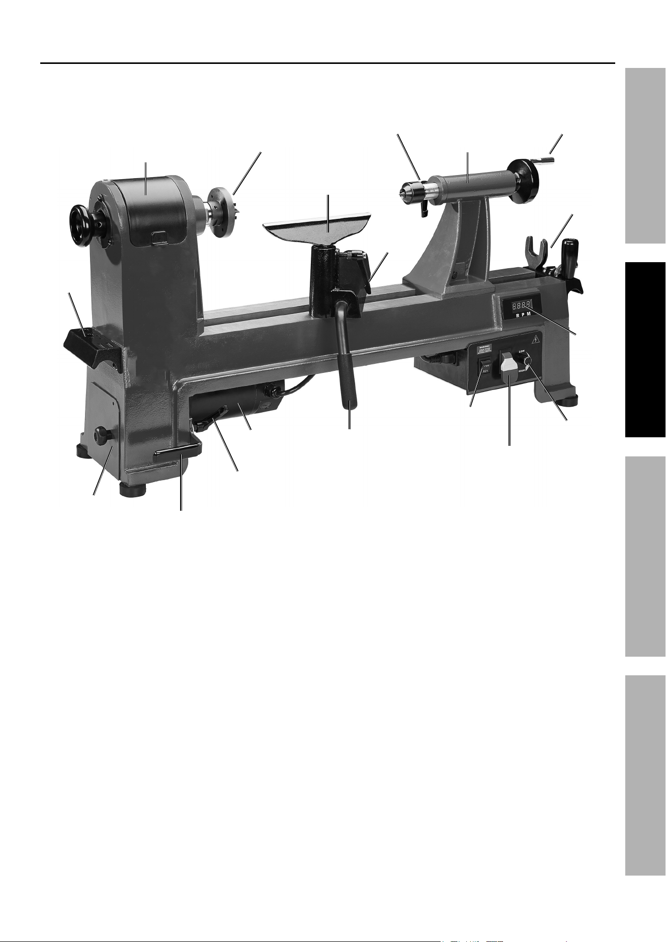
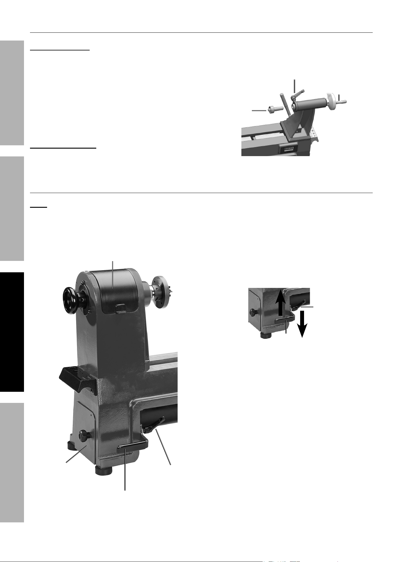
Functions
Belt access Door
tool rest
Base Locking
Handle
tailstock
Handle
Digital
readout
Speed Dial
power Switch
with Safety Key
Directional
Switch
Motor
Storage
Bracket
tool rest
Lock
Storage
Bracket
Motor position Lock
Motor tension
Lever
Faceplate
Quill Locking Handle
Belt pulley Hatch
Page 8 For technical questions, please call 1-800-444-3353. Item 59583
SaFety OperatiOn MaintenanceSetup
Operating instructions
read the entire iMpOrtant SaFety inFOrMatiOn section at the beginning of this
manual including all text under subheadings therein before set up or use of this product.
tool Set up
tO preVent SeriOuS inJury FrOM acciDentaL OperatiOn:
turn the power Switch of the tool off, remove the Safety Key, and unplug the tool
from its electrical outlet before performing any procedure in this section.
tO preVent SeriOuS inJury:
DO nOt Operate WitH any GuarD DiSaBLeD, DaMaGeD, Or reMOVeD.
Moving guards must move freely and close instantly.
performing a test run
1. Place the Belt (205) into its lowest position.
(For instructions on Belt movement, refer
to Adjusting Speed on page 10.)
2. Pull out Indexing Pin Knob (21) and rotate
so that Detent is seated on the Roll Pin.
3. Turn Speed Dial (200) fully counterclockwise.
4. Connect machine to power supply.
5. Set Directional Switch (200) to FOR (forward)
position. Pull out on Power Switch (200) to
start Spindle (33), and slowly turn Speed Dial
clockwise. The Digital Readout (75) will light up,
and Spindle will rotate down toward front of Lathe.
6. Turn Speed Dial fully counterclockwise.
7. Push in Power Switch to OFF position.
8. Set Directional Switch to REV (reverse)
position, set Power Switch to ON position,
then slowly turn Speed Dial clockwise.
9. When operating correctly, machine will run
smoothly with little to no vibration or rubbing noises.
Spindle should rotate up toward rear of Lathe.
10. Turn machine off.
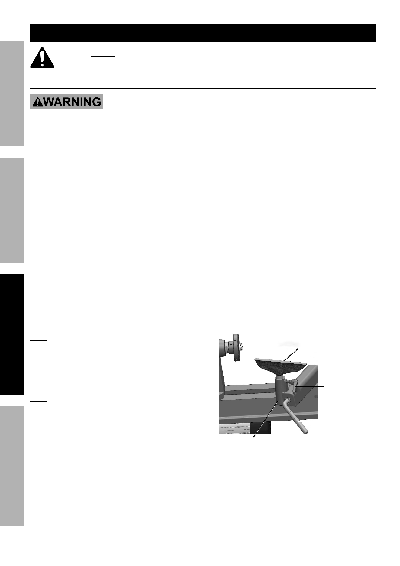
tool rest adjustment
note: Adjustments to the Tool Rest can be
made based on the work being done.
1. The Tool Rest Locking Lever (207) locks Tool Rest
Base (208) in position. Loosen the Lever to slide
Tool Rest Base along lathe bed. Tighten Lever
firmly when Tool Rest is properly positioned.
note: There is a nut underneath the Tool Rest
Base that should be tightened periodically to
allow the Locking Lever to tighten properly.
2. Loosen the Tool Rest Locking Handle (59)
to position Tool Rest at a desired angle
or height. Tighten Handle firmly when
Tool Rest is properly positioned.
tool rest (209)
Locking
Handle (59)
Locking
Lever (207)
tool rest Base (208)
Page 9For technical questions, please call 1-800-444-3353.Item 59583
SaFetyOperatiOnMaintenance Setup
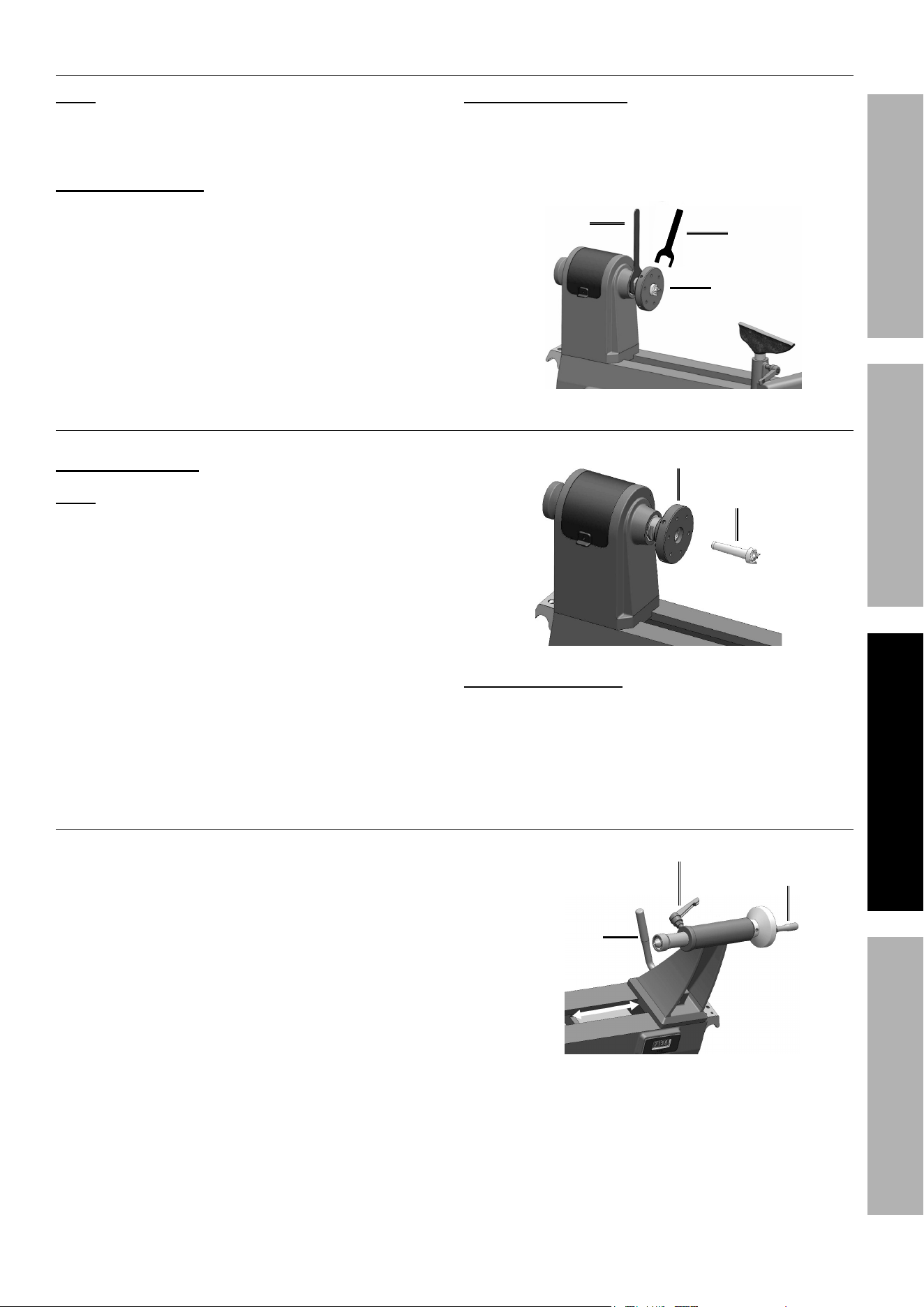
assembling Faceplate
note: The Faceplate is used for turning
bowls and plates. When installing Faceplate,
mount the workpiece onto Faceplate prior to
installing Faceplate on the Headstock.
to install Faceplate:
1. Thread Faceplate (35) onto Spindle
by turning it clockwise.
2. Hold Spindle in place with Wrench (77).
Place second Wrench (77) on flats of
Faceplate and turn to tighten Faceplate.
3. Tighten two Set Screws (34) on
Faceplate with Hex Wrench (78).
to remove Faceplate:
1. Loosen the two Faceplate Set Screws.
2. Hold Spindle in place with Wrench (77), while
loosening Faceplate with second Wrench (77).
Wrench (77)
Wrench (77)
Faceplate (35)
installing/removing Spur center
install Spur center:
note: Spur Center can be used with or
without Faceplate mounted to spindle.
1. Make sure the mating surfaces of both the Spur
Center (36) and Spindle are clean. Use an acetone-
moistened cloth to remove any other debris, oil, etc.
2. Drive Spur Center into the workpiece, using
a rubber mallet or a piece of scrap wood.
3. Push Spur Center into the Spindle.
Spur (36)
Faceplate
remove Spur center:
1. Hold Spur Center to prevent it from falling. Use a
rag to protect your hand from the sharp edges.
2. Insert Knockout Rod through the spindle
hole to tap out the Spur Center.
tailstock adjustment
1. Loosen the Tailstock Locking Lever (48) and
slide Tailstock (39) along the lathe bed into the
desired position. Retighten Locking Lever.
2. Loosen the Quill Lock (40) just enough to unlock
the Quill (38). Turn Handwheel (43) clockwise
to move Quill forward. Turn counterclockwise
to retract Quill. Retighten Quill Lock.
Quill Lock (40)
Handwheel (43)
tailstock Locking
Lever (48)
Page 10 For technical questions, please call 1-800-444-3353. Item 59583
SaFety OperatiOn MaintenanceSetup
Setting up tailstock Live center
install Live center:
a. Rotate the Handwheel clockwise three
times to move Quill forward.
b. Make sure the mating surfaces are clean.
Push the Live Center (37) into the Quill.
c. If the Quill becomes fully retracted when the
Live Center is mounted, it will dismount the
Live Center. This is normal. Remount Live
Center by extending the Quill approximately
0.5 inch and pushing the Live Center in place.
remove Live center:
a. Hold the Live Center to prevent it
from falling. Use a cloth to protect
your hand from the sharp edges.
b. Rotate Handwheel counterclockwise
to retract the Quill until the Live Center
is released from the Quill.
Handwheel (43)
Live
center (37)
Quill Lock (40)
adjusting Speed
note: Start at slower speeds for rough cuts and
larger workpieces. Use faster speeds for refined
cuts and detailed work. Set the desired speed
range by adjusting the Belt position. Change the
speed within a speed range using the Speed Dial.
Speed is displayed on the Digital Readout.
Motor position
Lock
Motor tension Lever
Belt pulley Hatch
Belt access Door
1. Always turn off and unplug machine
before changing Belt position.
2. Open Belt Access Door (27).
3. Loosen Motor Position Lock (3). The Screw (9)
at the center of the Lock can be loosened
to rotate Handle to an optimal position.
4. Pull upwards on the Motor Tension
Lever (202) to relieve tension on the Belt.
Lock
Lever
5. Tighten Motor Lock to hold position.
6. Pull Belt Pulley Hatch (223) open using its knob.
7. Adjust the Belt’s position on both Spindle
Pulley (204) and Motor Pulley (203) to the
desired speed range setting. Ensure that the
Belt is vertically aligned on both pulleys.
8. Loosen Motor Position Lock and lower the Tension
Lever to its original position, then push down
on the Tension Lever using 15 lbs of pressure
until there is approximately 1/2″ deflection when
pressing the Belt midway between pulleys.
9. Tighten the Motor Position Lock.
10. Close both the Belt Access Door
and Belt Pulley Hatch.
11. Turn Speed Dial while spindle is moving to
select speed within the established range.

Page 11For technical questions, please call 1-800-444-3353.Item 59583
SaFetyOperatiOnMaintenance Setup
using the indexer
note: Indexing creates evenly spaced features around
the circumference of the workpiece while keeping
the Spindle locked. There are 24 index positions in
the spindle Pulley, each 15° apart, to help rotate the
workpiece evenly for accurately spaced features.
1. Turn off Lathe and disconnect from power.
2. Push in Indexer Knob and rotate Spindle
by hand until Knob engages with hole
on indexer pulley. Make sure the Spindle
is locked before starting to Index.
3. Disengage Indexer Knob when done.
upper Belt access panel
Spindle pulley
indexer
Knob
cautiOn! always disengage the indexer
Knob before restarting the lathe.
Workpiece and Work area Set up
1. Designate a work area that is clean and well-lit.
The work area must not allow access by children
or pets to prevent distraction and injury.
2. Lathe must be located on a surface capable of
bearing the combined weight of Lathe and intended
workpiece. The surface must be able to withstand
the vibration generated by Lathe during operation.
3. Lathe must be level, left-to-right and
front-to-back, or spindle may rotate
improperly and become damaged.
4. Route the power cord along a safe route to reach
the work area without creating a tripping hazard or
exposing the power cord to possible damage. The
power cord must reach the work area with enough
extra length to allow free movement while working.
5. There must not be objects, such as utility lines,
nearby that will present a hazard while working.
General Operating instructions
1. Make sure that the Switch is in the off-position,
then plug in the tool.
2. Make sure the workpiece is suitable for turning.
No extreme bows, knots, or cracks should exist.
3. Prepare and trim workpiece with a bandsaw
or table saw to make it roughly concentric.
4. Install workpiece between centers, or
attach it to faceplate or chuck.
5. Adjust tool rest according to type of operation,
and set minimum clearance between
workpiece and lip of tool rest to 1⁄4″ gap.
6. Rotate workpiece by hand to verify
spindle and workpiece rotate freely
throughout full range of motion.
7. Verify that pulley speed range is set for type
of wood and size of workpiece installed.
8. Verify that Speed Dial is turned fully
counterclockwise so that the Spindle does
not start at an excessive speed.
9. Verify that Directional Switch is
in the neutral position.
10. Put on safety glasses, face shield, and respirator.
11. Set Directional Switch to forward or reverse,
start Spindle, adjust spindle′s speed, and
begin turning operation, keeping chisel against
Tool Rest the entire time that it is cutting.
12. Turn Spindle OFF when cutting
operation is complete.
13. Remove Safety Key and unplug tool from
its electrical outlet. Clean, then store the
tool indoors out of children′s reach.

Page 12 For technical questions, please call 1-800-444-3353. Item 59583
SaFety OperatiOn MaintenanceSetup
Spindle turning
Spindle Turning is performed when a workpiece
is mounted between centers. Bowls, table
legs, tool handles, and candlesticks are
typical Spindle Turning projects.
Spindle turning Operation:
1. Mark both ends of the workpiece by drawing
diagonal lines from corner to corner. The
intersection point of these two lines will
indicate the center of the workpiece.
2. Use a wood mallet and punch or nail to
tap the point of the center of the workpiece
so that it leaves a center mark.
cautiOn! Do not drive workpiece onto Spur Center
while Spur Center is mounted in headstock.
3. Using a 1⁄4″ drill bit, drill a hole at center mark on
end of the workpiece to be mounted on Spur Center.
penciL LineS
MarKeD DiaGOnaLLy
acrOSS cOrnerS
WOrKpiece
4. To embed Spur Center into workpiece, cut 1⁄8″
saw kerfs in the Headstock-end of workpiece along
the diagonal lines that were marked in Step 1.
5. If workpiece is over 2″ x 2″, cut corners off
lengthwise to make turning safer and easier.
6. Drive Spur Center into end center mark with a wood
mallet to embed it at least 1⁄4″ into workpiece.
7. With workpiece still attached, insert Spur
Center into headstock spindle.
note: Use Tool Rest to support opposite end
of workpiece so that workpiece and Spur
Center do not separate during installation.
8. Install Live Center into Tailstock Quill and tighten
Quill-Lock Handle to lock Quill in position.
9. Slide Tailstock towards workpiece until the end
of the Live Center touches the center mark of
workpiece. Lock Tailstock in this position.
10. Loosen Quill Lock Handle and Rotate
Tailstock HandWheel (43) to push Live
Center into workpiece at least 1⁄4″.
11. Properly adjust Tool Rest to the workpiece.
12. Before beginning lathe operation, rotate
workpiece by hand to ensure that there
is safe clearance on all sides.
Spindle turning tips
1. When turning the lathe ON, stand out of the
path of the spinning workpiece until the Spindle
reaches full speed and workpiece is secured.
2. Use the slowest speed when
starting or stopping the lathe.
3. Select the right speed for the size of
workpiece that you are turning.
4. Keep the tool on the Tool Rest the entire
time it is in contact with workpiece.
5. Learn the correct techniques for each tool
you will use. If you are unsure about how
to use the lathe tools, seek training from
experienced and knowledgeable lathe users.
6. Practice on scrap material to become familiarized
with the operation process and make the necessary
adjustments before working on your work piece.
Bowl turning
Mounting the workpiece onto the Faceplate:
1. For bowls or plates with a large diameter, mount to
the Faceplate for the maximum amount of support.
note: While Faceplates are the most reliable method
for holding a larger block of wood for turning, a lathe
chuck can also be used. A chuck is useful when
working on more than one piece at a time, allowing
the user to open the chuck and change workpieces
instead of having to remove the mounting screws.

Page 13For technical questions, please call 1-800-444-3353.Item 59583
SaFetyOperatiOnMaintenance Setup
2. Select a stock that is at least .2 inches
(51 mm) larger than each dimension
of the finished work piece.
3. Remove any bark from the top of the
wood stock (that will be later attached
onto a Faceplate or in a chuck).
4. True one of the surfaces of the workpiece for
mounting against the Faceplate. Using the
Faceplate as a template, mark the location
of the mounting holes on the workpiece and
drill pilot holes of the appropriate size.
5. If the mounting screws on the Faceplate
interfere with the workpiece, a waste block can
be used. Shape the waste block so that it is of
the same diameter as the Faceplate. Flatten
the mating surfaces of the waste block and the
workpiece. Use a high quality glue suitable for
the particular workpiece to prevent the piece from
falling off during operation. Glue waste block
to the workpiece securely. If you plan to use a
chuck, turn the waste block into a tenon of the
appropriate length and diameter to fit your chuck.
Shaping the inside Of a Bowl/plate
1. Turn off machine and move Tailstock out of the way.
2. Mount workpiece onto Faceplate and
attach Faceplate to Headstock.
3. Adjust the Tool Rest to be just below the centerline
and at a right angle to the machine’s turning axis.
4. Rotate workpiece by hand to check for
proper seating and clearance.
5. Lightly shear across the top of the bowl from
rim to center. Place a bowl gouge tool on the
Tool Rest at center of the workpiece with the
flute facing the top of the bowl. The tool handle
should point toward the four o’clock position.
6. Control the cutting edge of the gouge with the
left hand, while swinging Handle around towards
your body with the right hand. The flute should
start out facing the top of the workpiece, rotating
it upwards as it moves deeper into the bowl to
maintain a clean and even curve. As the tool goes
deeper into the bowl, progressively work outward
towards the rim of the bowl. Turn the Tool Rest
into the piece as you get deeper into the bowl.
7. Develop the preferred wall thickness at the rim
and maintain it as you work deeper into the
bowl. When the interior is finished, move Tool
Rest back to the exterior to re-define bottom of
the bowl. Work the area around the Faceplate
with a bowl gouge. Begin the separation with a
parting tool, but do not cut all the way through.
Page 14 For technical questions, please call 1-800-444-3353. Item 59583
SaFety OperatiOn MaintenanceSetup
Maintenance and Servicing
procedures not specifically explained in this manual must
be performed only by a qualified technician.
tO preVent SeriOuS inJury FrOM acciDentaL OperatiOn:
turn the power Switch of the tool off, remove the Safety Key, and unplug the tool
from its electrical outlet before performing any procedure in this section.
tO preVent SeriOuS inJury FrOM tOOL FaiLure:
Do not use damaged equipment. if abnormal noise or vibration
occurs, have the problem corrected before further use.
cleaning, Maintenance, and Lubrication
1. BeFOre eacH uSe, inspect the general
condition of the tool. Check for:
• loose hardware,
• misalignment or binding of moving parts,
• cracked or broken parts,
• damaged electrical wiring, and
• any other condition that may
affect its safe operation.
2. aFter uSe, wipe external surfaces
of the tool with clean cloth.
3. Periodically, wear ANSI-approved safety goggles
and NIOSH-approved breathing protection and blow
dust out of the motor area using dry compressed air.
4. cautiOn! if power tool is
damaged, it must be repaired only by
a qualified service technician.
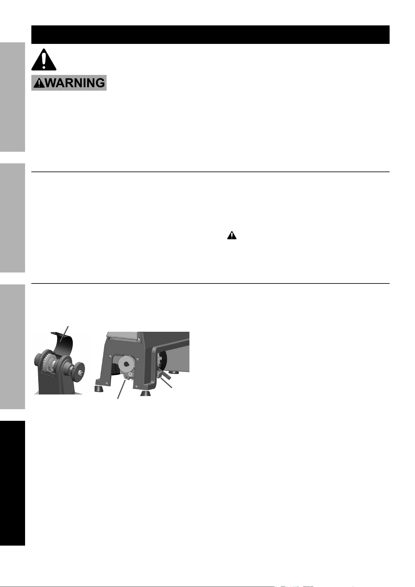
Belt replacement
1. Open Belt Access Door and Belt Pulley Hatch,
then loosen Motor Position Lock and raise Motor
Tension Lever in order to de-tension the Belt.
Belt access Door
pulley Hatch Opening
tension Lever
2. Move Belt into smallest Motor Pulley
and largest Spindle Pulley.
3. While holding Spindle in place using the Spindle
Wrench, remove Screw from the Handwheel
and unthread Handwheel from Spindle.
4. Remove Belt by sliding it off of Motor Pulley
and up past the edge of the Spindle Pulley.
5. Reverse the above process to install new belt.

Page 15For technical questions, please call 1-800-444-3353.Item 59583
SaFetyOperatiOnMaintenance Setup
troubleshooting
problem possible causes Likely Solutions
Tool will not start. 1. Cord not connected.
2. No power at outlet.
3. Tool’s thermal reset breaker
tripped (if equipped).
4. Internal damage or wear. (Carbon
brushes or switch, for example.)
1. Check that cord is plugged in.
2. Check power at outlet. If outlet is unpowered,
turn off tool and check circuit breaker.
If breaker is tripped, make sure circuit is right
capacity for tool and circuit has no other loads.
3. Turn off tool and allow to cool.
Press reset button on tool.
4. Have technician service tool.
Tool operates
slowly.
Extension cord too long or
wire size too small.
Eliminate use of extension cord. If an extension cord
is needed, use one with the proper diameter for its
length and load. See table a on page 3.
Performance
decreases
over time.
1. Accessory dull or damaged.
2. Carbon brushes worn or damaged.
1. Keep cutting accessories sharp.
Replace as needed.
2. Have qualified technician replace brushes.
Excessive noise
or rattling.
1. Internal damage or wear. (Carbon
brushes or bearings, for example.)
2. Belt too loose (slipping) or
too tight (bearing damage).
1. Have technician service tool.
2. Properly tension belt.
Overheating. 1. Forcing machine to work too fast.
2. Accessory dull or damaged.
3. Blocked motor housing vents.
4. Motor being strained by long or
small diameter extension cord.
1. Allow machine to work at its own rate.
2. Keep cutting accessories sharp.
Replace as needed.
3. Wear ANSI-approved safety goggles and
NIOSH-approved dust mask/respirator while
blowing dust out of motor using compressed air.
4. Eliminate use of extension cord.
If an extension cord is needed, use one with
the proper diameter for its length and load.
See table a on page 3.
Follow all safety precautions whenever diagnosing or servicing the tool.
Disconnect power supply and remove the Safety Key before service.
error codes
error code Description Solution
F1 Low voltage protection
(20% lower than standard)
Check voltage, then restart Lathe.
F2 High voltage protection
(20% higher than standard)
Check voltage, then restart Lathe
F3 Incorrect operation of reverse Turn off Main Switch. Restart Lathe
after Digital Readout shows zero.

Page 16 For technical questions, please call 1-800-444-3353. Item 59583
SaFety OperatiOn MaintenanceSetup
part Description Qty
1 Foot 4
3 Motor Position Lock 1
4 Washer 2
6 Head Cap Screw 4
9 Cap Screw 1
10 Bed 1
12 Phillip Head Screw 3
14 Cap Screw 4
15 Washer 8
16 Storage Bracket 2
17 Cap Screw 4
18 Spring Washer 4
19 Headstock 1
20 Spindle Speed Sensor 1
21 Indexer/Spindle Lock 1
24 Headstock Handwheel 1
25 Locking Nut 1
27 Belt Access Door 1
28 Cap Screw 2
29 Set Screw 2
30 Bearing 1
31 Ring 2
32 Bearing 1
33 Spindle 1
34 Cap Screw 2
35 FacePlate 1
36 Spur Center 1
37 Live Center 1
38 Quill 1
39 Tailstock 1
40 Quill Lock Handle 1
41 Pin 1
42 Lead Screw 1
43 Tailstock Handwheel 1
44 Handwheel Axle 1
45 Washer 1
46 Handwheel Handle 1
47 Set Screw 1
48 Tailstock Locking Lever 1
part Description Qty
50 Tailstock Clamp Bolt 1
51 Tailstock Clamp 2
52 Lock Nut 2
53 C-Ring 1
57 C-Ring 2
59 Tool Rest Lock Handle 1
60 Tool Rest Clamp Bolt 1
71 Phillips Screw 2
75 Digital Readout 1
77 Wrench 2
78 Hex Wrench 3mm 1
79 Hex Wrench 4mm 1
80 Hex Wrench 5mm 1
81 Hex Wrench 12mm 1
82 Handle Sleeve 1
84 Headstock Cover 1
86 Power Cord 1
200 Control Box Assembly 1
201 Motor 1
202 Motor Tension Lever 1
203 Motor Pulley 1
204 Spindle Pulley 1
205 Belt 1
207 Tool Rest Lock Lever 1
208 Tool Rest Base 1
209 8" Tool Rest 1
210 Control Box Bracket 2 1
211 Control Box Bracket 1 1
212 Washer 6
213 Screw 6
214 Screw 4
215 Carbon Brush 2
216 Carbon Brush Cap 2
220 Knockout Rod 1
221 Screw 3
222 Pointer 1
223 Belt Pulley Hatch 1
224 Screw 1
225 Magnet 1
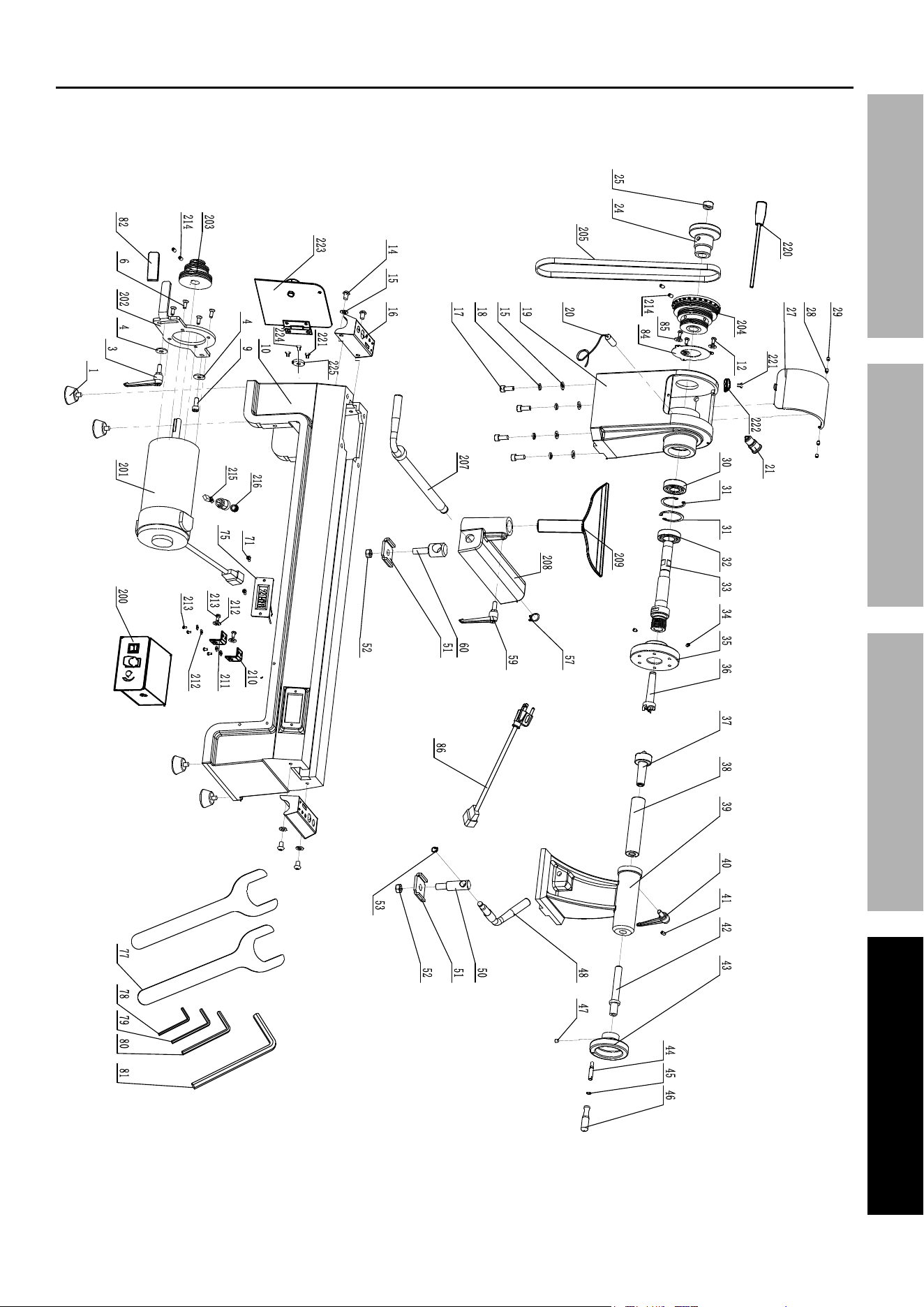
parts List and Diagram
pLeaSe reaD tHe FOLLOWinG careFuLLy
THE MANUFACTURER AND/OR DISTRIBUTOR HAS PROVIDED THE PARTS LIST AND ASSEMBLY DIAGRAM
IN THIS MANUAL AS A REFERENCE TOOL ONLY. NEITHER THE MANUFACTURER OR DISTRIBUTOR
MAKES ANY REPRESENTATION OR WARRANTY OF ANY KIND TO THE BUYER THAT HE OR SHE IS
QUALIFIED TO MAKE ANY REPAIRS TO THE PRODUCT, OR THAT HE OR SHE IS QUALIFIED TO REPLACE
ANY PARTS OF THE PRODUCT. IN FACT, THE MANUFACTURER AND/OR DISTRIBUTOR EXPRESSLY
STATES THAT ALL REPAIRS AND PARTS REPLACEMENTS SHOULD BE UNDERTAKEN BY CERTIFIED AND
LICENSED TECHNICIANS, AND NOT BY THE BUYER. THE BUYER ASSUMES ALL RISK AND LIABILITY
ARISING OUT OF HIS OR HER REPAIRS TO THE ORIGINAL PRODUCT OR REPLACEMENT PARTS
THERETO, OR ARISING OUT OF HIS OR HER INSTALLATION OF REPLACEMENT PARTS THERETO.
parts List
Page 17For technical questions, please call 1-800-444-3353.Item 59583
SaFetyOperatiOnMaintenance Setup
assembly Diagram

Page 18 For technical questions, please call 1-800-444-3353. Item 59583
SaFety OperatiOn MaintenanceSetup
record product’s Serial number Here:
note: If product has no serial number, record month and year of purchase instead.
note: Some parts are listed and shown for illustration purposes only, and are not available
individually as replacement parts. Specify UPC 193175476166 when ordering parts.

Page 19For technical questions, please call 1-800-444-3353.Item 59583
SaFetyOperatiOnMaintenance Setup
Limited 90 Day Warranty
Harbor Freight Tools Co. makes every effort to assure that its products meet high quality and durability standards,
and warrants to the original purchaser that this product is free from defects in materials and workmanship for the
period of 90 days from the date of purchase. This warranty does not apply to damage due directly or indirectly,
to misuse, abuse, negligence or accidents, repairs or alterations outside our facilities, criminal activity, improper
installation, normal wear and tear, or to lack of maintenance. We shall in no event be liable for death, injuries
to persons or property, or for incidental, contingent, special or consequential damages arising from the use of
our product. Some states do not allow the exclusion or limitation of incidental or consequential damages, so the
above limitation of exclusion may not apply to you. THIS WARRANTY IS EXPRESSLY IN LIEU OF ALL OTHER
WARRANTIES, EXPRESS OR IMPLIED, INCLUDING THE WARRANTIES OF MERCHANTABILITY AND FITNESS.
To take advantage of this warranty, the product or part must be returned to us with transportation charges
prepaid. Proof of purchase date and an explanation of the complaint must accompany the merchandise.
If our inspection verifies the defect, we will either repair or replace the product at our election or we may
elect to refund the purchase price if we cannot readily and quickly provide you with a replacement. We will
return repaired products at our expense, but if we determine there is no defect, or that the defect resulted
from causes not within the scope of our warranty, then you must bear the cost of returning the product.
This warranty gives you specific legal rights and you may also have other rights which vary from state to state.

26677 agoura road • calabasas, ca 91302 • 1-800-444-3353