8b
7x
6
3
9
4
10a
8c
2x
12
1
7
11
10b
2x
15
5b
10a
10b
10
8a
5a 5b 7
8 11
5
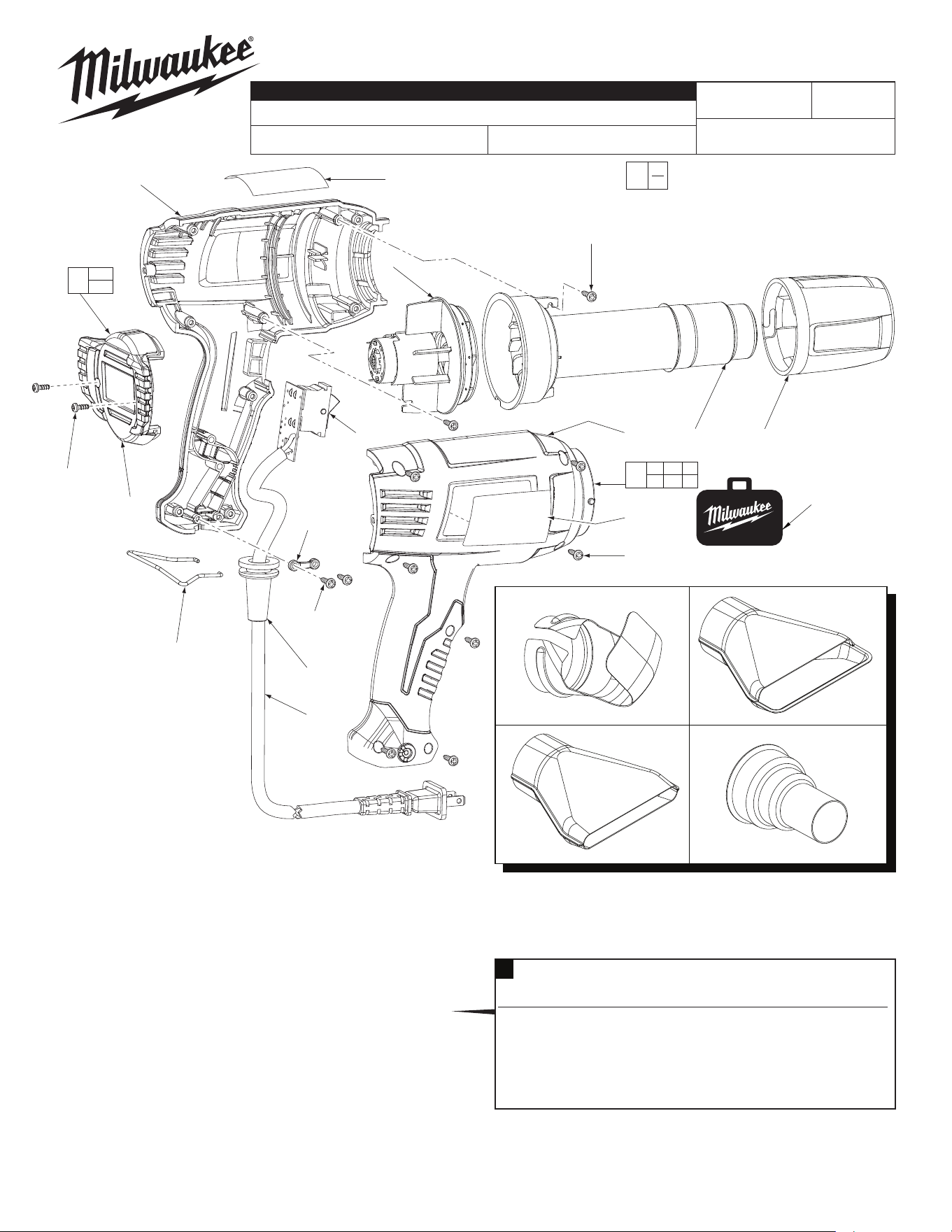
Cat. No. 49-80-0300
Heat Gun Accessory Assortment
Includes the four accessories listed above.
49-80-0292
Hook Nozzle
49-80-0293
Air
Deflector
Nozzle
49-80-0294
Air
Spreader
Nozzle
49-80-0297
Air
Reducer
Nozzle
5a
8c
2x
54-05-0641
731A
54-05-0642
Nov. 2022
See Page 2
REVISED BULLETIN
SERVICE PARTS LIST
BULLETIN NO.
WIRING INSTRUCTION
DATE
SPECIFY CATALOG NO. AND SERIAL NO. WHEN ORDERING PARTS
STARTING
SERIAL NO.
MILWAUKEE TOOL
l
www.milwaukeetool.com
13135 W. LISBON RD., BROOKFIELD, WI 53005
Drwg. 5
= Part number change from
previous service parts list.
14
FIG. PART NO. DESCRIPTION OF PART NO. REQ.
1 22-64-8975 Cord Set (1)
3 --------------- Heating Element Assembly (1)
4 14-46-8974 Motor and Fan Assembly (1)
5 14-46-8977 Handle Service Kit (1)
5a --------------- Left Handle Halve (1)
5b --------------- Right Handle Halve (1)
6 14-46-8976 Switch/PCBA (1)
7 12-20-8975 Service Nameplate Kit (1)
8 14-46-8979 Repair Service Kit (Includes all t items) (1)
8a --------------- Cord Clamp (1)
8b --------------- M3 x 13 Phillips Pan Hd. Screw (7)
8c --------------- M3 x 13 Phillips Pan Hd. Screw (4)
9 44-90-8975 Nose Shield (1)
10 31-12-8975 End Cap Service Kit (1)
10a --------------- End Cap (1)
10b --------------- M3.5 x 8 Phillips Pan Hd. Screw (2)
11 10-20-0112 Warning Label (1)
12 44-76-8975 Strain Relief (1)
14 42-55-8975 Carrying Case (1)
15 --------------- Wire Tool Support (1)
t
t
t
t
t
t 14-46-8979 Repair Service Kit
Consists of:
Fig. Description of Part Where Used Color Qty.
10b M3.5 x 8 Phillips Pan Hd. Screw End Cap Black 2
8b M3 x 13 Phillips Pan Hd. Screw Right Handle Black 7
8c M3 x 13 Phillips Pan Hd. Screw Heating Element Chrome 2
8c M3 x 13 Phillips Pan Hd. Screw Cord Clamp Chrome 2
15 Wire Tool Support Handle Halves ----- 1
8a Cord Clamp Left Handle ----- 1
8
EXAMPLE:
Component Parts (Small #) Are Included
When Ordering The Assembly (Large #).
00
0
HEAT GUN, Double Insulated
CATALOG NO.
8975-6
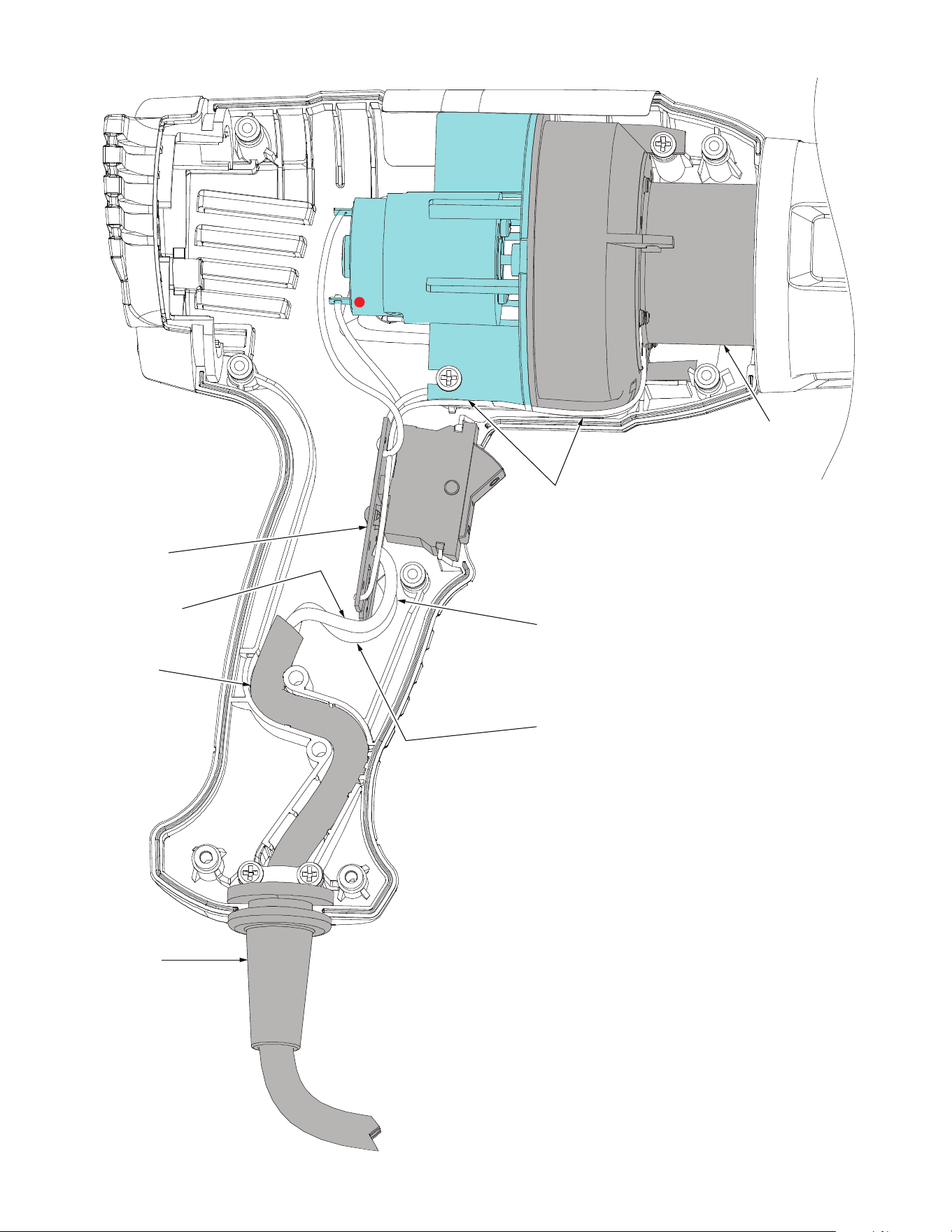
Switch/PCBA
Black Cord Wire
Power Cord
Strain Relief
Heating
Element
NOTE:
Route all wires and sleeves from the bottom of the
Heating Element as shown. Be sure all wires are
routed under the Heating Element. Be sure those
wires are routed behind the Motor and Fan and
below the screw boss.
When replacing the Power Cord, solder ‘Black’ lead
to the upper position on the PCBA marked ‘ACL”.
Solder the ’White’ lead to the lower position on the
PCBA marked ‘ACN”.
White Cord Wire